

Page 1
RELAYS
FAN SAFETY ALARM CIRCUITS
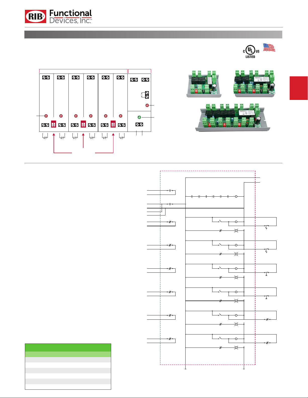
RIBMNLB-6/-4/-2
2.75˝ Track Mount AHU Fan Safety Alarm and General Purpose
Logic Circuit, 24 Vac/dc Power Input, 2/4/6 Outputs
Isolated Dry Contact Outputs,
Each Rated 1.5A @ 24 Vac/dc
R1 OUT
R2 OUT
R3 OUT
R4 OUT
R5 OUT
N/C
N/C
N/C
N/C
R1
R2
R3
R4
Alarm
Input
Indicators
CLOSED
21
OPEN
R1 R1 COM R2 R2 COM R3 R3 COM R4 R4 COM R5 R5 COM R6 R6 COM
Alarm
Input 1
Alarm
Input 2
CLOSED
43
OPEN
Alarm
Input 3
Alarm Input
Bypass Switches
Alarm
Input 4
Alarm
Input 5
SPECIFICATIONS
Expected Relay Life:
Operating Temperature:
Humidity Range:
Operate Time:
Power Input:
Alarm Status:
Dimensions:
Track Mount:
Approvals:
Housing Rating:
Gold Flash:
Override Switch:
Notes:
• Track mount models shown above.
• RIBMNLB-6 and RIBLB-6 have six Alarm Inputs and one Master
Alarm. RIBMNLB-4 and RIBLB-4 have four Alarm Inputs and one Master
Alarm. RIBMNLB-2 and RIBLB-2 have two Alarm Inputs and one
Master Alarm.
Models RIBMNLB-6, RIBMNLB-4, and RIBMNLB-2; and RIBLB-6, RIBLB-4,
and RIBLB-2 are simply devices that combine a common relay-logic
function into a small, easy-to-install, and less expensive form.
A master relay will open if any one of the normally-closed (N/C) inputs
There are six, four, or two inputs depending on the model
open.
chosen. LED status of all inputs, the master relay, and power input
is provided. Bypass of un-used inputs is also provided. The RIBMNLB
series is provided with mounting track for mounting in user-provided
electrical enclosures. The RIBLB series is enclosed in a NEMA-1, 4˝ x
7˝ enclosure with a clear lid to allow viewing of the status LEDs. The
master relay has three general-purpose outputs: two 24 V output
terminals and one dry-contact output rated up to 10 Amp @ 277 Vac
(terminals on RIBMNLB series, wires on RIBLB series.) The most common application is an Air Handling Unit (AHU) fan-safety-shutdown
where the master relay is used to shutdown the fan. Contact closure
outputs are provided so that a DDC controller can determine the
cause of a shutdown.
10 million cycles minimum mechanical
-30 to 140° F
5 to 95% (noncondensing)
8ms
4 Amp max. @ 24 Vac/dc ; 50-60 Hz
LED On = Activated
6.200˝ x 2.750˝ x 1.750˝ (RIBMNLB-6)
4.600˝ x 2.750˝ x 1.750˝ (RIBMNLB-4)
3.000˝ x 2.750˝ x 1.750˝ (RIBMNLB-2)
4.28˝ x 7.00˝ x 2.00˝ with .75˝ NPT Nipple
(RIBLB-6/-4/-2)
MT212-6 Mounting Track Provided (RIBMNLB-6)
MT212-4 Mounting Track Provided
(RIBMNLB-4, RIBMNLB-2)
UL Listed, UL916, UL864, C-UL
UL Listed, NEMA 1, C-UL, CE Approved,
UL Accepted for Use in Plenum
No
No
SELECTION GUIDE
Model# Inputs
RIBMNLB-6 6
RIBMNLB-4 4
RIBMNLB-2 2
RIBLB-6 6
RIBLB-4 4
RIBLB-2 2
MT212 Mounting Track
MT212 Mounting Track
MT212 Mounting Track
PE6020 Enclosure
PE6020 Enclosure
PE6020 Enclosure
R6 OUT
N/C
N/C
R5
R6
CLOSED
65
OPEN
Alarm
Input 6
RIBLB-6/-4/-2
Enclosed AHU Fan Safety Alarm and General Purpose
Logic Circuit, 24 Vac/dc Power Input, 2/4/6 Outputs
3A Total Sourced
from 24 Vac/dc Input
COM 24V COM 24V
R7 POLE 1
Master
Relay
R7
COM 24V
4A Max
10A @ 277 Vac
(Typically used to
shut down fan)
(Typically used
to shut down
other relays)
Low Temp Alarm
to DDC Controller
High Temp Alarm
to DDC Controller
Low Press Alarm
to DDC Controller
High Press Alarm
to DDC Controller
Smoke Alarm #1
to DDC Controller
Smoke Alarm #2
to DDC Controller
R7 POLE 2
24 Vac
10A @ 277 Vac
10A @ 24 Vdc
1/2 HP @ 120/240 Vac
B300 Pilot Duty
Max. Isolated Dry
Contact Output
Master Alarm
Indicator
24V Power
R7-2
R7-1
R1-2
R2-2
R3-2
R4-2
R5-2
R6-2
RIBMNLB-6 (Track Mount)
RIBLB-6 (Enclosed)
R6-1R5-1R4-1R3-1R2-1R1-1
Close bypass switch
if input not in use.
Input 1 Bypass
Input 1 Alarm Indicator
R1-3
Input 2 Bypass
Input 2 Alarm Indicator
R2-3
Input 3 Bypass
Input 3 Alarm Indicator
R3-3
Input 4 Bypass
Input 4 Alarm Indicator
R4-3
Input 5 Bypass
Input 5 Alarm Indicator
R5-3
Input 6 Bypass
Input 6 Alarm Indicator
R6-3
Made in USA
Meets
“Buy American”
of ARRA 2009
24 Vac Power Input
R7
Typical alarm inputs
shown below. Any alarm
inputs may be used and
in any order. (Alarm
inputs must be N/C.)
R1
R2
R3
R4
R5
R6
Input 1
Low Temp Alarm
Input 2
High Temp Alarm
Input 3
Low Press Alarm
Input 4
High Press Alarm
Input 5
Smoke Alarm #1
Input 6
Smoke Alarm #2
071417
 Loading...