

Page 1
FORM 146.00-EG5 (616)
MODEL RH
GEOTHERMAL HYDRONIC HEAT PUMP
ENGINEERING GUIDE
1.5–6 Tons
R-410A Refrigerant
Page 2

Page 3

Table of Contents
Model Nomenclature . . . . . . . . . . . . . . . . . . . . . . . . . . . . . . . . . . . . . . . . . . . . . . . . . . . . . . . . . . . . . . 4
The Hydronic Unit. . . . . . . . . . . . . . . . . . . . . . . . . . . . . . . . . . . . . . . . . . . . . . . . . . . . . . . . . . . . . . . 5-6
Inside the Hydronic Unit . . . . . . . . . . . . . . . . . . . . . . . . . . . . . . . . . . . . . . . . . . . . . . . . . . . . . . . . . . . 7
Water Quality . . . . . . . . . . . . . . . . . . . . . . . . . . . . . . . . . . . . . . . . . . . . . . . . . . . . . . . . . . . . . . . . . . . . 8
The Aurora Base Control System . . . . . . . . . . . . . . . . . . . . . . . . . . . . . . . . . . . . . . . . . . . . . . . . 9-12
Application Notes. . . . . . . . . . . . . . . . . . . . . . . . . . . . . . . . . . . . . . . . . . . . . . . . . . . . . . . . . . . . . .13-19
Dimensional Data . . . . . . . . . . . . . . . . . . . . . . . . . . . . . . . . . . . . . . . . . . . . . . . . . . . . . . . . . . . . . . . .20
Physical Data . . . . . . . . . . . . . . . . . . . . . . . . . . . . . . . . . . . . . . . . . . . . . . . . . . . . . . . . . . . . . . . . . . . . 21
Electrical Data . . . . . . . . . . . . . . . . . . . . . . . . . . . . . . . . . . . . . . . . . . . . . . . . . . . . . . . . . . . . . . . . . . . 21
Antifreeze Correction . . . . . . . . . . . . . . . . . . . . . . . . . . . . . . . . . . . . . . . . . . . . . . . . . . . . . . . . . . . . 22
RH SERIES ENGINEERING GUIDE
AHRI/ISO 13256-2 Performance Ratings . . . . . . . . . . . . . . . . . . . . . . . . . . . . . . . . . . . . . . . . . . . . 23
Pressure Drop . . . . . . . . . . . . . . . . . . . . . . . . . . . . . . . . . . . . . . . . . . . . . . . . . . . . . . . . . . . . . . . . . . .24
Reference Calculations . . . . . . . . . . . . . . . . . . . . . . . . . . . . . . . . . . . . . . . . . . . . . . . . . . . . . . . . . . . 25
Legend and Notes . . . . . . . . . . . . . . . . . . . . . . . . . . . . . . . . . . . . . . . . . . . . . . . . . . . . . . . . . . . . . . . 25
Performance Data. . . . . . . . . . . . . . . . . . . . . . . . . . . . . . . . . . . . . . . . . . . . . . . . . . . . . . . . . . . . .26-39
Wiring Schematics . . . . . . . . . . . . . . . . . . . . . . . . . . . . . . . . . . . . . . . . . . . . . . . . . . . . . . . . . . . 40-45
Accessories and Options. . . . . . . . . . . . . . . . . . . . . . . . . . . . . . . . . . . . . . . . . . . . . . . . . . . . . . .46-47
Engineering Guide Specifications . . . . . . . . . . . . . . . . . . . . . . . . . . . . . . . . . . . . . . . . . . . . . . 48-49
Revision Guide. . . . . . . . . . . . . . . . . . . . . . . . . . . . . . . . . . . . . . . . . . . . . . . . . . . . . . . . . . . . . . . . . . . 51
Page 4
RH SERIES ENGINEERING GUIDE
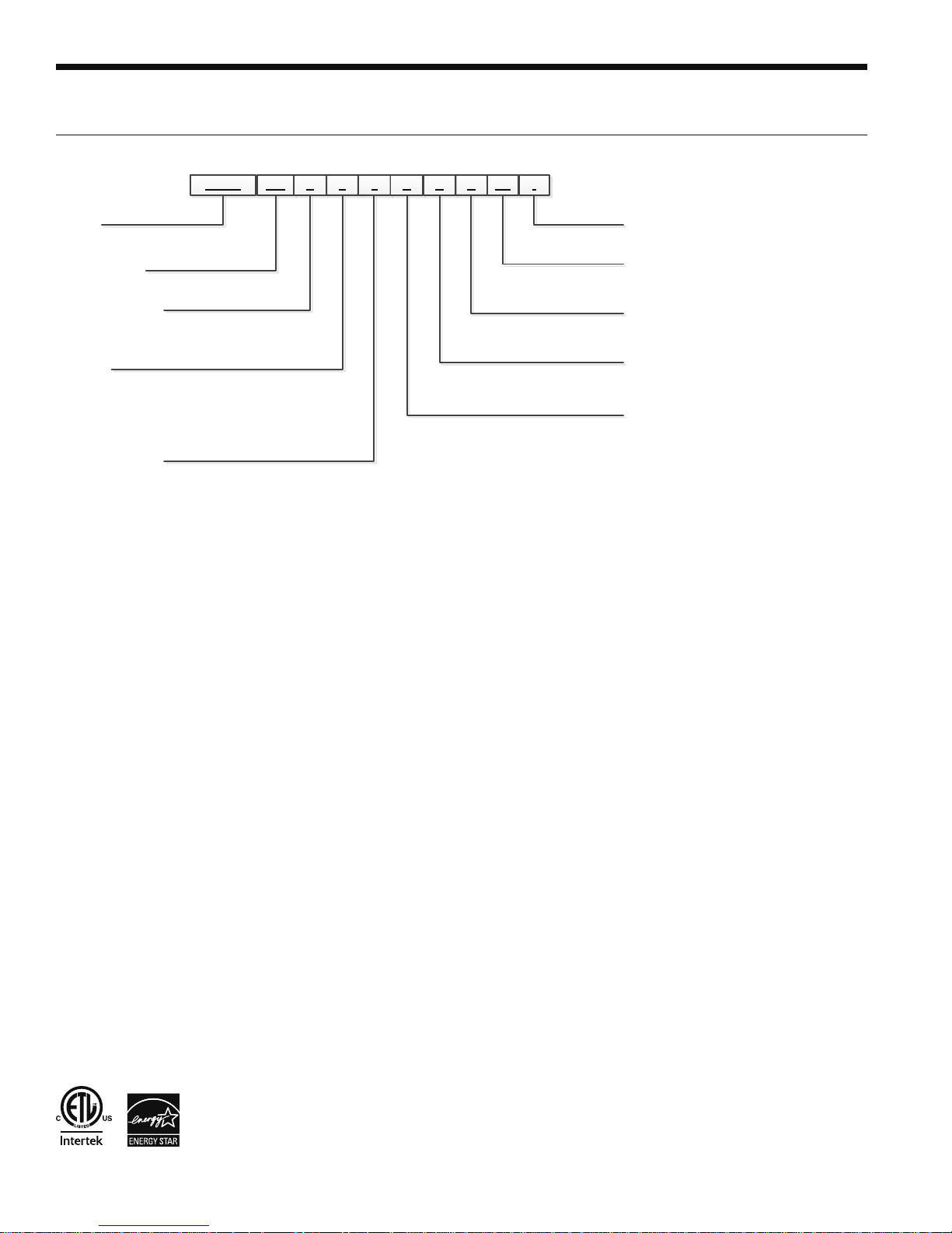
Model Nomenclature
1-4
5-7 8 9 10 11 12
RHSW 050 R 0 0 A C
Model
RHSW – RH Series Hydronic
Heat Pump
Unit Capacity
018, 025, 040, 050, 060, 075
Reversible Option
H- Heating Only
R- Reversible
Voltage
0 – 208-230/60/1 (Commercial)
2 – 265/60/1 (025 & 050 only)
3 – 208-230/60/3 (040-075)
4 – 460/60/3 (025-075)
5 – 575/60/3 (040-075)
Hot Water Option
0 – No Hot Water Generation, No IntelliStart
2 – Hot Water Generation, No IntelliStart
3 – No Hot Water Generation, IntelliStart
5 – Hot Water Generation, IntelliStart
1,3
13
C
14-15
SS *
16
Vintage
* – Factory Use Only
Future Option
SS – Standard
Load Coax
C – Copper
N – Cupronickel
Source Coax
C – Copper
N – Cupronickel
Controls Option
A – Aurora™ Base Controls (ABC)
Rev.: 10 June 2016
2
NOTES: 1 – Available on 040, 050, 060, and 075 only. Hot water generator requires field installed external pump kit.
2 – 018 and 025 heating only models are available only with copper double wall vented load coax for potable water,
and are not designed to be converted to dedicated cooling units.
3 – IntelliStart not available on 265/60/1 and 575/60/3 voltages.
RH Series hydronic units are Safety listed under UL1995 thru ETL and performance tested in accordance
with standard AHRI/ISO 13256-2. AHRI does not currently certify water-to-water products under AHRI/
ISO 13256-2.
4
4
Page 5
The Single Hydronic Series
RH SERIES ENGINEERING GUIDE
Features
High efficiency copper coaxial
heat exchanger (vented
double walled available only
on 018 and 025 "heating only"
models)
Optional IntelliStart
reduces starting current
by 60-70%
Field switchable control
box (end to end) for
application flexibility
Insulated and corrosion
resistant cabinet to
reduce noise
Aurora controls
Aurora "Base" Controls
Dual isolation compressor
mounts to reduce noise
and vibration
Captive FPT water connections
eliminate 'egg-shaping' backup
Discharge Muffler Helps
quiet compressor gas
pulsations
Zero ODP and low GWP
R-410A refrigerant
Optional Hot Water
Generator available on
040-075
High efficiency copper or
cupronickel coaxial heat
exchangers
Full refrigerant suction
tube, heat exchanger, and
waterline insulation to prevent
condensation at low loop
temperatures
High efficiency scroll
compressors for improved
reliability
Compressor sound
blankets for reduced noise
Standard waterlines out the
front (field switchable to back
via control box)
wrench
What’s New?
• AuroraTM Communicating Control Features
- Traditional Safety Sensors: HP, LP, condensate overflow,
freeze detection loop, freeze detection load.
- Communicating Modular Design: Communicating modular
design for flexibility and expandability
5
Page 6

RH SERIES ENGINEERING GUIDE
Single Hydronic Series cont.
High Efficiency
Large oversized water-to-water refrigerant heat exchangers and
scroll compressors provide extremely efficient operation. The
Aurora Controls extend this innovation and performance.
Operating Efficiencies
• Environmentally friendly R-410A refrigerant reduces
ozone depletion.
• An optional hot water generator is available on 040,
050, 060, and 075 to generate hot water at considerable
savings while improving overall system efficiency.
• High-stability bidirectional expansion valve provides
superior performance.
• Efficient scroll compressors operate quietly.
• Oversized coaxial tube water-to-refrigerant heat
exchanger increases efficiency.
Standard Features
• Heavy gauge cabinet
• Quiet scroll compressors in all models
• All interior cabinet surfaces are insulated with
[12.7 mm] thick 1
1
⁄2 lb. [681 g] density, surface coated,
1
⁄2 in.
acoustic type glass fiber insulation.
• Optional IntelliStart
®
to reduce starting current
(208-230/60/1)
• Field switchable control box
• Ultra-compact cabinet
• Multi-density laminate lined compressor blanket designed
to suppress low frequency noise.
• Discharge line mufflers to help quiet compressor
discharge gas pulsations.
Product Quality
• Heavy-gauge steel cabinets are finished with a durable
polyester powder coat paint for long lasting beauty
and service.
• All refrigerant brazing is performed in a nitrogen atmosphere.
• The 018H and 025H are available with load side copper
vented double wall coaxial heat exchangers.
• Coaxial heat exchangers, refrigerant suction lines, hot water
generator, and all water pipes are fully insulated to reduce
condensation problems in low temperature operation.
• Computer controlled deep vacuum and refrigerant
charging system.
• All joints are leak detected for maximum leak rate of
less than
• Computer bar code equipped assembly line ensures all
components are correct.
• All units are computer run-tested with water to verify
both function and performance.
• Safety features include high- and low-pressure refrigerant
controls to protect the compressor; hot water high-limit
hot water generator pump shutdown.
1
⁄4 oz. per year.
Easy Maintenance and Service Advantages
• Removable compressor access panels.
• Quick attach wiring harnesses are used throughout for
fast servicing.
• High and low pressure refrigerant service ports.
Options and Accessories
• Optional hot water generator with externally mounted
pump (230/60/1) and water heater plumbing connector.
• Closed loop, source side, circulating pump kit
• Closed loop, load side, circulating pump kit
• Water connection kits
• Geo-Storage Tank (80-120 Gal.)
• IntelliStart
• HydroZone, tank control with outdoor reset
• HydroLogic
• HydroStat, communicating set point control
Application Flexibility
• Designed to operate with entering source temperature of
25°F and leaving load temperatures of 40°F to 130°F. See
the capacity tables to see allowable operating conditions
per model.
• Source side flow rates as low as 1.5 GPM/ton for well
water, 50°F [10°C] min. EWT.
• Dedicated heating and heat pump models available.
• Dedicated non-reversible models are shipped as
heating only; field convertible to cooling only.
• Modularized unit design and primary/secondary
controls for optimum capacity matching and staging.
• Stackable for space conservation (to a maximum 3
units high).
• Compact size allows installation in confined spaces.
• Front or rear plumbing connections.
• Control Panel location is reversible.
6
Page 7
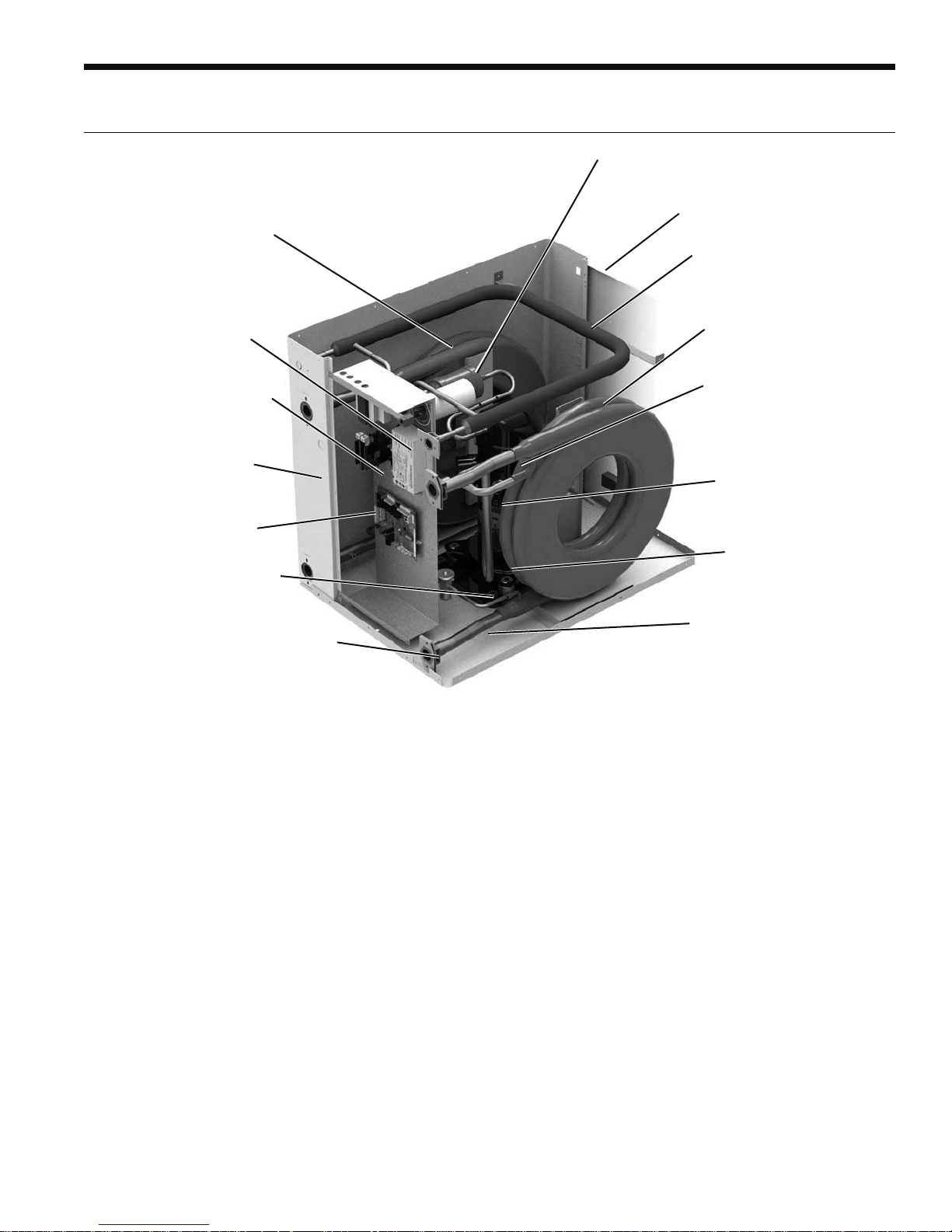
Inside The Single Hydronic Series
RH SERIES ENGINEERING GUIDE
Refrigerant
Our products all feature zero ozone depletion and low
global warming potential R-410A refrigerant.
Cabinet
All units are constructed of corrosion resistant galvanized
sheet metal with powder coat paint rated for more than
1000 hours of salt spray. Lift-out access panels provide
access to the compressor section from two sides.
Compressors
High efficiency R-410A scroll compressors are used on every
model. Scrolls provide both the highest efficiency available
and great reliability.
Electrical Box
The control box is "field" movable from front to back for ease
of application. Separate knockouts for low voltage, and two
for power on, front and back, allow easy access to the control
box. Large 75VA transformer assures adequate controls power
for accessories.
Water Connections
Flush mount FPT water connection fittings allow one wrench
leak-free connections and do not require a backup wrench.
Factory installed water line thermistors can be viewed through
the microprocessor interface tool.
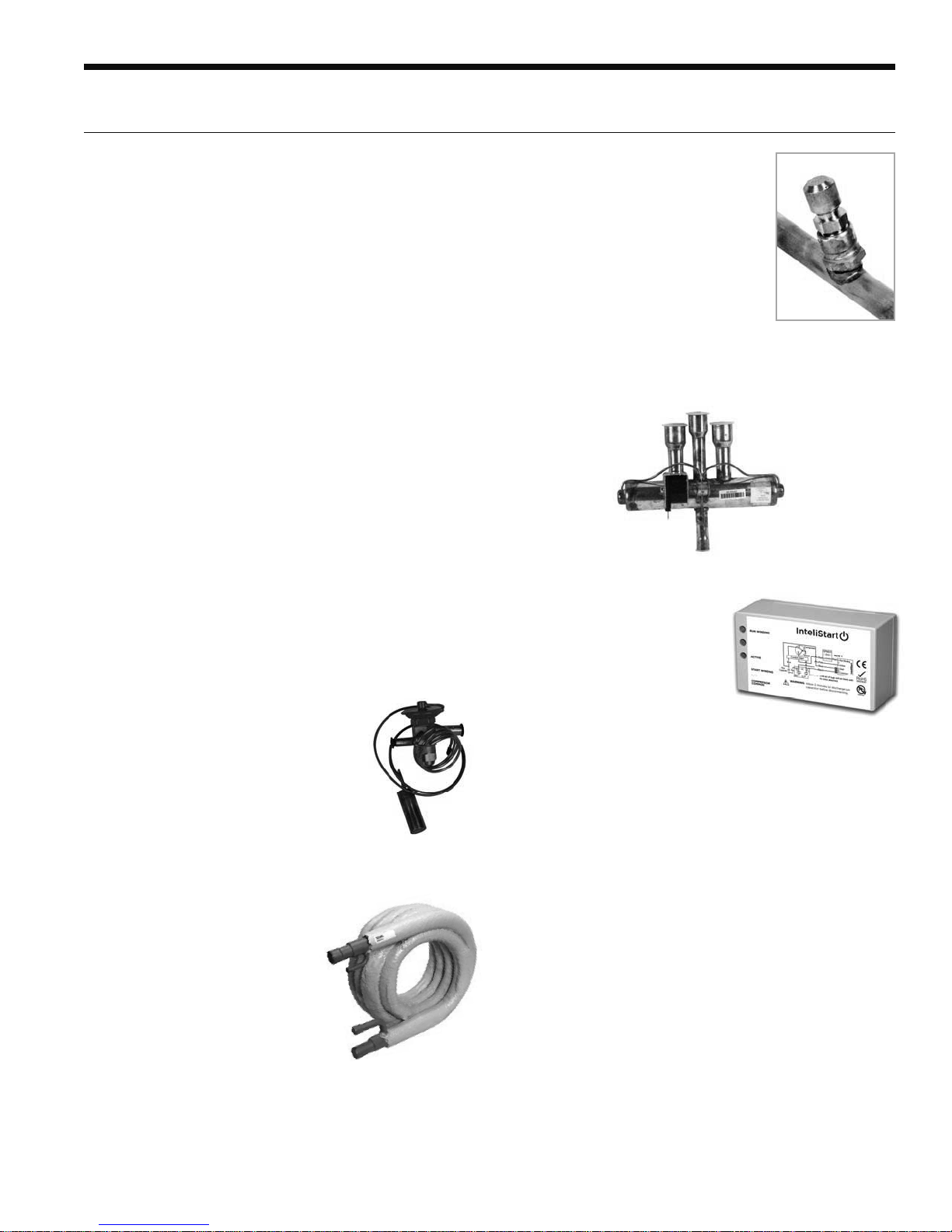
Thermostatic Expansion Valve
All models utilize a balanced port
bidirectional thermostatic expansion
valve (TXV) for refrigerant metering.
This allows precise refrigerant flow in a
wide range of entering water variation
(25 to 120°F [-7 to 49°C]) found in
geothermal systems. The TXV is located
in the compressor compartment for easy
access.
Service Connections and
Serviceability
Two Schrader service ports are
provided for each unit. The suction
side and discharge side ports are for
field charging and servicing access. All
valves are 7/16 in. SAE connections.
4-Way Reversing Valve
Units feature a reliable all-brass pilot operated refrigerant
reversing valve. The reversing valve operation is limited to
change of mode by the control to enhance reliability.
IntelliStart
The optional IntelliStart single
phase soft starter will reduce
the normal start current (LRA)
by 60-70%. This allows the
heat pump to go off-grid.
Using IntelliStart also provides
a substantial reduction in
light flicker, reduces start-up noise, and improves the
compressor's start behavior. IntelliStart is available in a field
retrofit kit or as a factory installed option. IntelliStart is
available on 208-230/60/1 voltage.
Water-to-Refrigerant Heat Exchanger Coil
Large oversized coaxial refrigerantto-water heat exchangers provide
unparalleled efficiency. The coaxes
are designed for low pressure drop
and low flow rates. All coaxes are
pressure rated to 450 psi water side
and 600 psi on the refrigerant side.
Refrigerant-to-water heat exchangers
will be coated with ThermaShield
to prevent condensation in low
temperature loop operation. Vented,
double walled heat exchanger suitable
for potable water systems are standard
on 018-025 heating only models.
7
Page 8
RH SERIES ENGINEERING GUIDE
Water Quality
General
Water-to-water heat pumps may be successfully applied
in a wide range of residential and light commercial
applications. It is the responsibility of the system designer
and installing contractor to ensure that acceptable water
quality is present and that all applicable codes have been
met in these installations. Failure to adhere to the guidelines
in the water quality table could result in loss of warranty.
Application
These heat pumps are not intended for direct coupling to
swimming pools and spas. If used for this type of application, a secondary heat exchanger must be used. Failure to
supply a secondary heat exchanger for this application will
result in warranty exclusion for primary heat exchanger corrosion or failure.
Water Treatment
Do not use untreated or improperly treated water.
Equipment damage may occur. The use of improperly
treated or untreated water in this equipment may result in
scaling, erosion, corrosion, algae or slime. The services of a
qualified water treatment specialist should be engaged to
determine what treatment, if any, is required. The product
warranty specifically excludes liability for corrosion,
erosion or deterioration of equipment.
The heat exchangers and water lines in the units are copper
or cupronickel tube. There may be other materials in the
building’s piping system that the designer may need to take
into consideration when deciding the parameters of the
water quality.
If an antifreeze or water treatment solution is to be used,
the designer should confirm it does not have a detrimental
effect on the materials in the system.
Contaminated Water
In applications where the water quality cannot be held to
prescribed limits, the use of a secondary or intermediate
heat exchanger is recommended to separate the unit from
the contaminated water.
The following table outlines the water quality guidelines
for unit heat exchangers. If these conditions are exceeded,
a secondary heat exchanger is required. Failure to supply
a secondary heat exchanger where needed will result in a
warranty exclusion for primary heat exchanger corrosion
or failure.
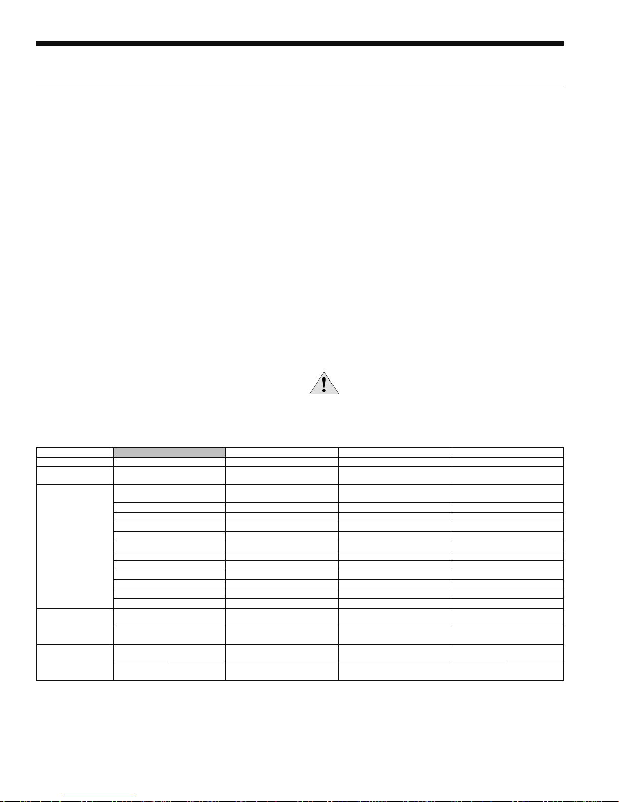
WARNING: Must have intermediate heat
exchanger when used in pool and spa
applications.
Water Quality Guidelines
Material Copper 90/10 Cupronickel 316 Stainless Steel
pH Acidity/Alkalinity
Scaling
Corrosion
Iron Fouling
(Biological Growth)
Erosion
NOTES: Grains = ppm divided by 17
mg/L is equivalent to ppm
Calcium and
Magnesium Carbonate
Hydrogen Sulfide
Chlorine Less than 0.5 ppm Less than 0.5 ppm Less than 0.5 ppm
Chlorides Less than 20 ppm Less than 125 ppm Less than 300 ppm
Carbon Dioxide Less than 50 ppm 10 - 50 ppm 10 - 50 ppm
Ammonia Less than 2 ppm Less than 2 ppm Less than 20 ppm
Ammonia Chloride Less than 0.5 ppm Less than 0.5 ppm Less than 0.5 ppm
Ammonia Nitrate Less than 0.5 ppm Less than 0.5 ppm Less than 0.5 ppm
Ammonia Hydroxide Less than 0.5 ppm Less than 0.5 ppm Less than 0.5 ppm
Ammonia Sulfate Less than 0.5 ppm Less than 0.5 ppm Less than 0.5 ppm
Total Dissolved Solids (TDS) Less than 1000 ppm 1000 - 1500 ppm 1000 - 1500 ppm
LSI Index +0.5 to -0.5 +0.5 to -0.5 +0.5 to -0.5
Iron, FE
Bacterial Iron Potential
Iron Oxide
Suspended Solids
Threshold Velocity
(Fresh Water)
Less than 0.5 ppm (rotten egg
Sulfates Less than 125 ppm Less than 125 ppm Less than 200 ppm
2
+ (Ferrous)
smell appears at 0.5 ppm)
Less than 1 ppm, above this
level deposition will occur
Less than 10 ppm and filtered
for max. of 600 micron size
7 - 9 7 - 9 7 - 9
(Total Hardness)
less than 350 ppm
< 0.2 ppm < 0.2 ppm < 0.2 ppm
< 6 ft/sec < 6 ft/sec < 6 ft/sec
(Total Hardness)
less than 350 ppm
10 - 50 ppm Less than 1 ppm
Less than 1 ppm, above this
level deposition will occur
Less than 10 ppm and filtered
for max. of 600 micron size
(Total Hardness)
less than 350 ppm
Less than 1 ppm, above this
level deposition will occur
Less than 10 ppm and filtered
for max. of 600 micron size
2/22/12
8
Page 9
RH SERIES ENGINEERING GUIDE
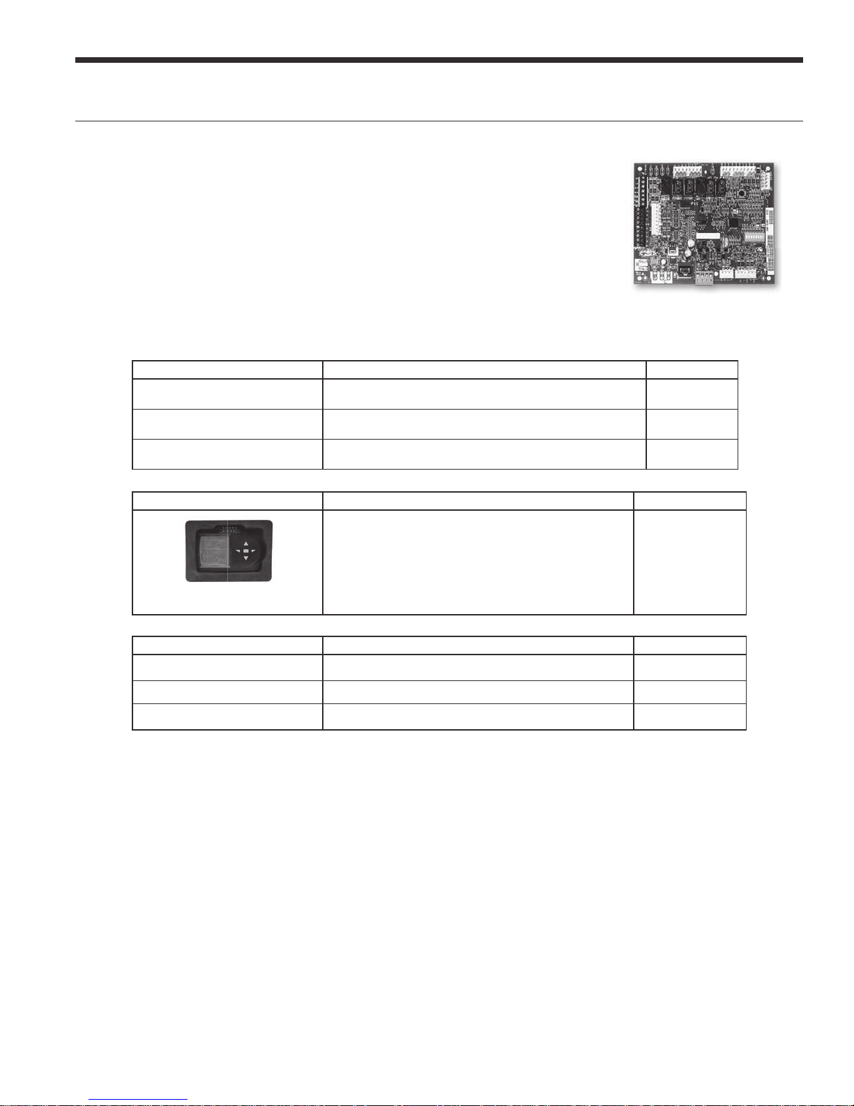
The Aurora Base Control System
Aurora ‘Base’ Control
The Aurora ‘Base’ Control (ABC) System is a complete residential and commercial comfort
system that brings all aspects of the HVAC system into one cohesive module network. The
ABC features microprocessor control and HP, LP, condensate and freeze detection, over/
under voltage faults, along with communicating thermostat capability for complete fault
detection text at the thermostat.
Aurora uses the Modbus communication protocol to communicate between modules. Each
module contains the logic to control all features that are connected to the module. The
Aurora ‘Base’ Control (ABC) has two Modbus channels. The rst channel is congured as a
master for connecting to devices such as a communicating thermostat, expansion board, or other satellite devices. The second
channel is congured as a satellite for connecting the Aurora Interface Diagnostics T
Aurora Control Features Description Aurora ‘Base’
Microprocessor Compressor Control
Base Hot Water Generator
Operation
Base Loop Pump Control
Microprocessor control of compressor for timings with FP1, HP,
LP, Condensate, assignable Acc relay
Compressor Contactor powers Hot Water Generator Pump with
inline circuit breaker and thermostat limit.
Compressor Contactor powers Loop Pump with inline circuit
breaker and no loop pump linking capability.
ool (AID Tool).
•
•
•
Service Device Description Aurora ‘Base’
Allows setup, monitoring and troubleshooting of any
Aurora Control.
NOTE: Although the ABC has basic compatibility with all
Aurora, new product features may not be available on older
AID Tools. To simplify the basic compatibility ensure the
Aurora Interface and Diagnostics
(AID) Tool
Add On Thermostats and Zoning Description Aurora ‘Base’
HydroStat
HZO
HZC
version of AID is at least the same or greater than the ABC
software version.
Communicating controller for one hydronic heat pump. Optional
Non-communicating controller for up to four heat pumps. Optional
Non-communicating controller for one hydronic heat pump Optional
For Service
(Ver. 1.xx or greater)
9
Page 10

RH SERIES ENGINEERING GUIDE
The Aurora Base Control System cont.
Aurora ‘Base’ Control
NOTE: Refer to the Aurora Base Control Application and
Troubleshooting Guide and the Instruction Guide: Aurora
Interface and Diagnostics (AID) Tool for additional information.
Control Features
• Random start at power up
• Anti-short cycle protection
• High and low pressure cutouts
• Loss of charge
• Water coil freeze detection
• Over/under voltage protection
• Load shed
• Emergency shutdown
• Diagnostic LED
• Test mode push button switch
• Alarm output
• Accessory output with N.O. and N.C.
• Modbus communication (master)
• Modbus communication (satellite)
Field Selectable Options via Hardware
DIP Switch (SW1) – Test/Conguration Button (See SW1
Operation Table)
Test Mode
The control is placed in the test mode by holding the push
button switch SW1 for 2 - 5 seconds. In test mode most of
the control timings will be shortened by a factor of sixteen
(16). LED3 (green) will ash at 1 second on and 1 second
o. Additionally, when entering test mode LED1 (red) will
ash the last lockout one time. Test mode will automatically
time out after 30 minutes. Test mode can be exited by
pressing and holding the SW1 button for 2 to 5 seconds or
y cycling the power. NOTE: Test mode will automatically
b
be exited after 30 minutes.
Reset Conguration Mode
The control is placed in reset conguration mode by
holding the push button switch SW1 for 50 to 60 seconds.
This will reset all conguration settings and the EEPROM
back to the factory default settings. LED3 (green) will turn
o when entering reset conguration mode. Once LED3
(green) turns o, release SW1 and the control will reset.
DIP Switch (SW2)
SW2-1 (Source) FP1 Selection – Low water coil temperature
limit setting for freeze detection. On = 30°F;
O = 15°F.
SW2-2 (Load) FP2 Selection – On = 30°F; O = 15 ° F
SW2-3 RV – O/B - thermostat type. Heat pump
thermostats with “O” output in cooling or “B”
output in Heating can be selected. On = O; O = B.
SW2-4 Access Relay Operation (P2)
and 2-5
Access Relay Operation SW2-4 SW2-5
Cycle with Blower n/a
Cycle with Compressor OFF OFF
Water Valve Slow Opening ON OFF
Cycle with Comm. T-stat Hum Cmd n/a
Cycle with Blower - (Not used on water-to-water)
Cycle with Compressor - The accessory relay will cycle
with the compressor output.
Water Valve Slow Opening - The accessory relay will
cycle and delay both the blower and compressor output
for 90 seconds.
SW2-6 CC Operation – selection of single or dual capacity
compressor. On = Single Stage; O = Dual Capacity
SW2-7 Lockout and Alarm Outputs (P2) – selection of a
continuous or pulsed output for both the LO and
ALM Outputs. On = Continuous; O = Pulsed
SW2-8 Future Use
Alarm Jumper Clip Selection
From the factory, ALM is connected to 24 VAC via JW2. By
cutting JW2, ALM becomes a dry contact connected to ALG.
Field Selectable Options via Software
(Selectable via the Aurora AID Tool)
Safety Features
The following safety features are provided to protect the
compressor, heat exchangers, wiring and other components
from damage caused by operation outside of design conditions.
Fuse – a 3 amp automotive type plug-in fuse provides
protection against short circuit or overload conditions.
Anti-Short Cycle Protection – 4 minute anti-short cycle
protection for the compressor.
Random Start – 5 to 80 second random start upon power up.
10
Page 11

The Aurora Base Control System cont.
RH SERIES ENGINEERING GUIDE
Fault Retry – in the fault condition, the control will stage off
the outputs and then “try again” to satisfy the thermostat
Y input call. Once the thermostat input calls are satisfied,
the control will continue on as if no fault occurred. If 3
consecutive faults occur without satisfying the thermostat
Y input call, then the control will go to Lockout mode.
Lockout – The Alarm output (ALM) and Lockout output (L)
will be turned on. The fault type identification display LED1
(Red) shall flash the fault code. To reset lockout conditions
with SW2-8 On, thermostat inputs “Y1”, “Y2”, and “W”
must be removed for at least 3 seconds. To reset lockout
conditions with SW2-8 Off, thermostat inputs “Y1”, “Y2”,
“W”, and “DH” must be removed for at least 3 seconds.
Lockout may also be reset by turning power off for at least
30 seconds or by enabling the emergency shutdown input
for at least 3 seconds.
High Pressure – fault is recognized when the Normally
Closed High Pressure Switch, P4-9/10 opens, no matter
how momentarily. The High Pressure Switch is electrically in
series with the Compressor Contactor and serves as a hardwired limit switch if an overpressure condition should occur.
Low Pressure - fault is recognized when the Normally
Closed Low Pressure Switch, P4-7/8 is continuously open
for 30 seconds. Closure of the LPS any time during the 30
second recognition time restarts the 30 second continuous
open requirement. A continuously open LPS shall not be
recognized during the 2 minute startup bypass time.
Loss of Charge – fault is recognized when the Normally
Closed Low Pressure Switch, P4-7/8 is open prior to the
compressor starting.
Freeze Detection (Source Coax) - set points shall be
either 30°F or 15°F. When the thermistor temperature
drops below the selected set point, the control shall begin
counting down the 30 seconds delay. If the thermistor
value rises above the selected set point, then the count
should reset. The resistance value must remain below the
selected set point for the entire length of the appropriate
delay to be recognized as a fault. This fault will be ignored
for the initial 2 minutes of the compressor run time.
Freeze Detection (Load Coax) - uses the FP2 input to
protect against ice formation on the coax. The FP2 input
will operate exactly like FP1.
Over/Under Voltage Shutdown - An over/under voltage
condition exists when the control voltage is outside the
range of 18 VAC to 30 VAC. If the over/under voltage
shutdown lasts for 15 minutes, the lockout and alarm relay
will be energized. Over/under voltage shutdown is selfresetting in that if the voltage comes back within range
of 18 VAC to 30 VAC for at least 0.5 seconds, then normal
operation is restored.
Operation Description
Power Up - The unit will not operate until all the inputs and
safety controls are checked for normal conditions. The unit
has a 5 to 80 second random start delay at power up. Then
the compressor has a 4 minute anti-short cycle delay after
the random start delay.
Standby In standby mode, Y1, Y2, W, DH, and G are not
active. Input O may be active. The blower and compressor
will be off.
Heating Operation
Heating, 1st Stage (Y1) - The compressor is energized 10
seconds after the Y1 input is received.
Cooling Operation
In all cooling operations, the reversing valve directly tracks
the O input. Thus, anytime the O input is present, the
reversing valve will be energized.
Cooling, 1st Stage (Y1, O) - The compressor is energized 10
seconds after the Y1 input is received.
Emergency Shutdown - Four (4) seconds after a valid ES
input, P2-7 is present, all control outputs will be turned off
and remain off until the emergency shutdown input is no
longer present. The first time that the compressor is started
after the control exits the emergency shutdown mode,
there will be an anti-short cycle delay followed by a random
start delay. Input must be tied to common to activate.
Load Shed - The LS input disables all outputs with the
exception of the blower output. When the LS input has been
cleared, the anti-short cycle timer and random start timer
will be initiated. Input must be tied to common to activate.
11
Page 12
RH SERIES ENGINEERING GUIDE
The Aurora Base Control System cont.
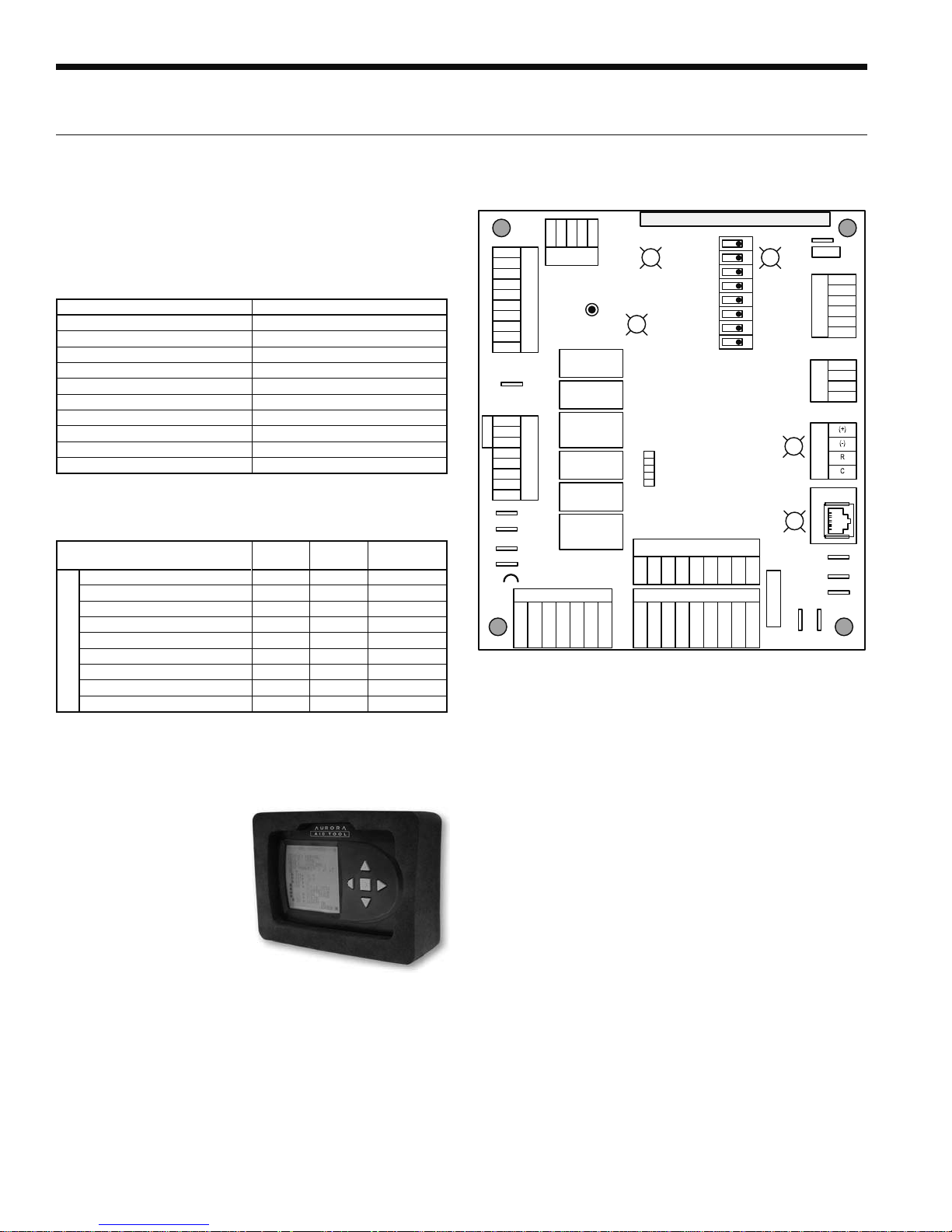
Aurora ‘Base’ Control LED Displays
These three LEDs display the status, configuration, and
fault codes for the control. These can also be read in plain
English via the Aurora AID Tool.
Status LED (LED3, Green)
Description of Operation Fault LED, Green
Normal Mode ON
Control is Non-functional OFF
Test Mode Slow Flash
Lockout Active Fast Flash
Dehumidification Mode Flash Code 2
(Future Use) Flash Code 3
(Future Use) Flash Code 4
Load Shed Flash Code 5
ESD Flash Code 6
(Future Use) Flash Code 7
Fault LED (LED1, Red)
Red Fault LED
LED Flash
Code*
Lockout
Normal - No Faults OFF –
Fault - Input 1 No Auto
Fault - High Pressure 2 Yes Hard or Soft
Fault - Low Pressure 3 Yes Hard or Soft
Fault - Freeze Detection FP2 4 Yes Hard or Soft
Fault - Freeze Detection FP1 5 Yes Hard or Soft
Fault - Condensate Overflow 7 Yes Hard or Soft
ABC Basic Faults
Fault - Over/Under Voltage 8 No Auto
Fault - FP1 & FP2 Sensor Error 11 Yes Hard or Soft
NOTE: All codes >11 use long flash for tens digit and short flash for the ones
digit. 20, 30, 40, 50, etc. are skipped.
Reset/
Remove
ABC Control Board Layout
C
CFM
CC
Y1
CC2
CC2
F
G
JW2 Alarm
FP2
FP2
FP1
FP1
REV
REV
CCG
PWM
HP
HP
LP
LP
G
LO
HI
CC
FG
F
R
ECM PWM
P4
P13
Fact ory
SW1 Test
RV – K1
CC – K2
P5
P2
ES
CC Hi – K3
Fact ory
Fan – K4
Alarm – K5
Acc – K6
LS
ALG
ALM
ACC c
ACC n c
ACC n o
FP1 – 15oF/30oF
FP2 – 15
RV – B/O
Fault
ACC – Dip 4
CC – Dual/Single
G
L – Pulse/Continuous
Status
ACC – Dip 5
Reheat/Normal
LED3
AURORA BASE
CONTROL™
Fact ory Use
P11
P9
Factory Fan Connection
C
R
LO
O/B
Field ConnectionsField Connections
P1
R
C
LO
O/B
o
F/30oF
G
G
Y1
Y1
Off
On
LED2LED1
1
YR
2
3
Config
4
5
6
7
8
SW2
Com1
Com2
W
Y2
DH
W
Y2
DH
3A-Fuse
G
G
RR
EH1
EH2
P3
C
EH1
C
Fact ory
CO
N/A
(+)
P6
(-)
R
RS485 Exp
C
P7
RS 485
P8
RS485 NET
CC
C
Aurora Interface and Diagnostics (AID) Tool
The Aurora Interface and
Diagnostics (AID) Tool is
a device that is a member
of the Aurora network.
The AID Tool is used to
troubleshoot equipment
which uses the Aurora
control via Modbus RTU
communication. The AID
Tool provides diagnostics,
fault management, ECM
setup, and system configuration capabilities to the Aurora
family of controls. An AID Tool is recommended, although
not required, for ECM airflow settings. The AID Tool simply
plugs into the exterior of the cabinet in the AID Tool port.
12
Page 13
Application Notes
RH SERIES ENGINEERING GUIDE
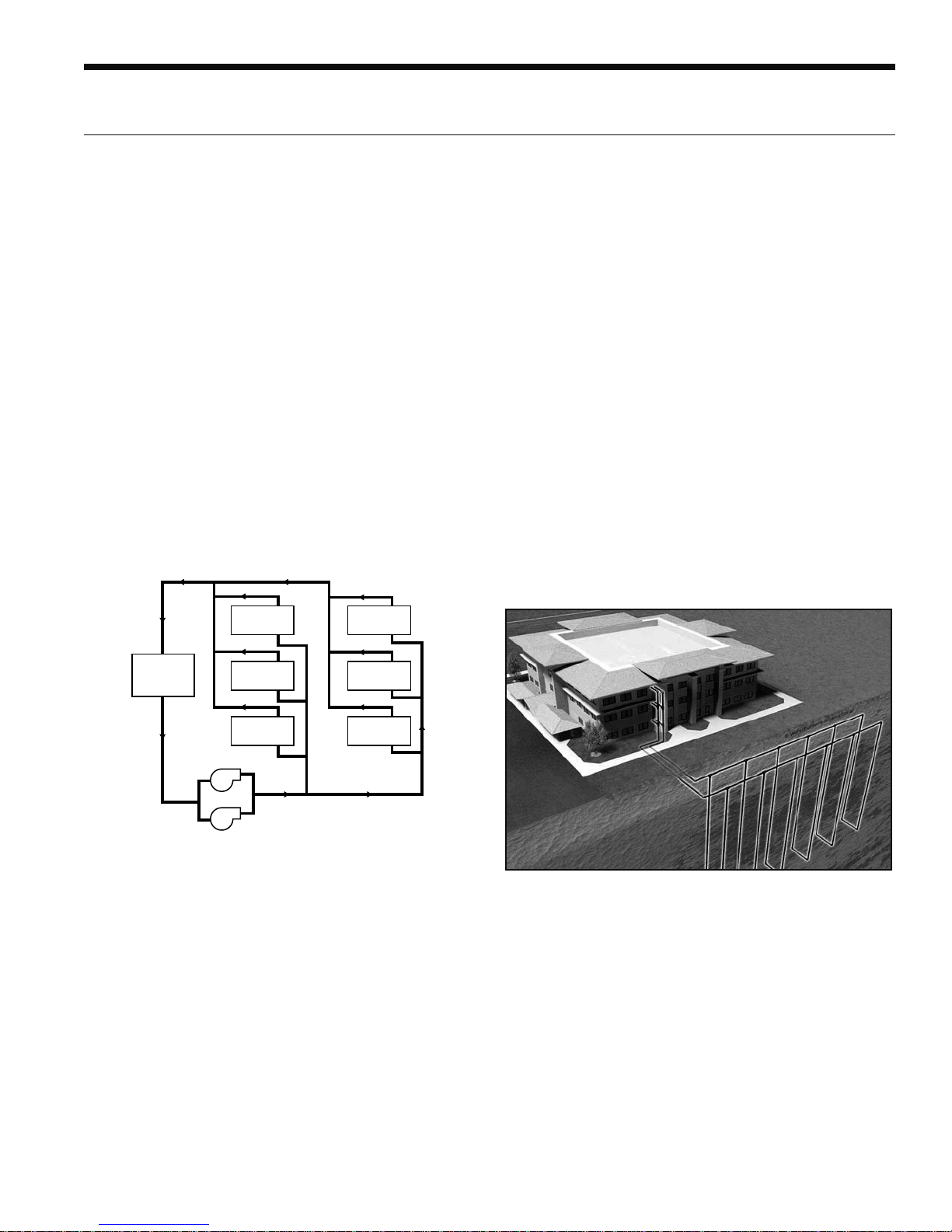
The Closed Loop Heat Pump Concept
The basic principle of a water source heat pump is the
transfer of heat into water from the space during cooling,
or the transfer of heat from water into the space during
heating. Extremely high levels of energy efficiency are
achieved as electricity is used only to move heat, not to
produce it. Using our typical water-to-water heat pump one
unit of electricity will move four to five units of heat.
When multiple water source heat pumps are combined
on a common circulating loop, the ultimate in energy
efficiency is created: The water-to-water units on cooling
mode are adding heat to the loop which the units in
heating mode can absorb, thus removing heat from the
area where cooling is needed, recovering and redistributing
that heat for possible utilization elsewhere in the system.
In modern commercial structures, this characteristic of
heat recovery from core area heat generated by lighting,
office equipment, computers, solar radiation, people or
other sources, is an important factor in the high efficiency
and low operating costs of our closed source heat pump
systems.
Return Water
Water-to-water
Unit
Water-to-water
Unit
low because units can be added to the loop on an "as
needed basis"- perfect for speculative buildings. Installed
costs are low since units are self-contained and can be
located adjacent to the occupied space, requiring minimal
ductwork. Maintenance can be done on individual units
without system shut-down. Conditions remain comfortable
since each unit operates separately, allowing cooling in
one area and heating in another. Tenant spaces can be
finished and added as needed. Power billing to tenants
is also convenient since each unit can be individually
metered: each pays for what each uses. Nighttime and/or
weekend uses of certain areas are possible without heating
or cooling the entire facility. A decentralized system also
means if one unit should fault, the rest of the system will
continue to operate normally, as well as eliminating air
cross-contamination problems and expensive high pressure
duct systems requiring an inefficient electric resistance
reheat mode.
The Best Approach
There are a number of proven choices in the type of system
which would be best for any given application. Most often
considered are:
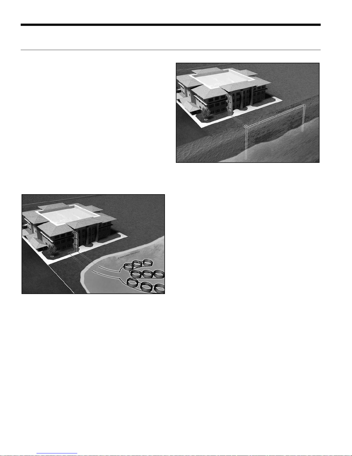
Vertical - Closed Loop/Ground Source
Heater/
Rejector
Pumps
Water-to-water
Unit
Water-to-water
Unit
Supply Water
Water-to-water
Unit
Water-to-water
Unit
In the event that a building's net heating and cooling
requirements create loop temperature extremes, our
units have the extended range capacity and versatility to
maintain a comfortable environment for all building areas.
Excess heat can be stored for later utilization or be added
or removed in one of three ways; by ground-source heat
exchanger loops: plate heat exchangers connected to other
water sources, or conventional cooler/boiler configurations.
Your sales representative has the expertise and computer
software to assist in determining optimum system type for
specific applications.
The Closed Loop Advantage
A properly applied water source heat pump system offers
many advantages over other systems. First costs are
• Closed Loop/Ground-Source Systems utilize the stable
temperatures of the earth to maintain proper water source
temperatures (via vertical or horizontal closed loop heat
exchangers) for our extended range heat pump system.
Sizes range from a single unit through many hundreds of
units. When net cooling requirements cause closed loop
water temperatures to rise, heat is dissipated into the
cooler earth through buried high strength plastic pipe "heat
exchangers." Conversely if net space heating demands
cause loop heat absorption beyond that heat recovered
from building core areas, the loop temperature will fall
causing heat to be extracted from the earth. Due to the
extended loop temperatures, AHRI/ISO 13256-1 Ground
Loop Heat Pumps are required for this application.
13
Page 14
RH SERIES ENGINEERING GUIDE
Application Notes cont.
Because auxiliary equipment such as a fossil fuel boiler
and cooling tower are not required to maintain the loop
temperature, operating and maintenance costs are very
low. Ground-source systems are most applicable in
residential and light commercial buildings where both
heating and cooling are desired, and on larger envelope
dominated structures where core heat recovery will not
meet overall heating loads. Both vertical and horizontally
installed closed-loops can be used. The land space
required for the "heat exchangers" is 100-250 sq. ft./ton
on vertical (drilled) installations and 750-1500 sq. ft./ton
for horizontal (trenched) installations. Closed loop heat
exchangers can be located under parking areas or even
under the building itself.
On large multi-unit systems, sizing the closed loop heat
exchanger to meet only the net heating loads and assisting
in the summer with a closed circuit cooling tower may be
the most cost effective choice.
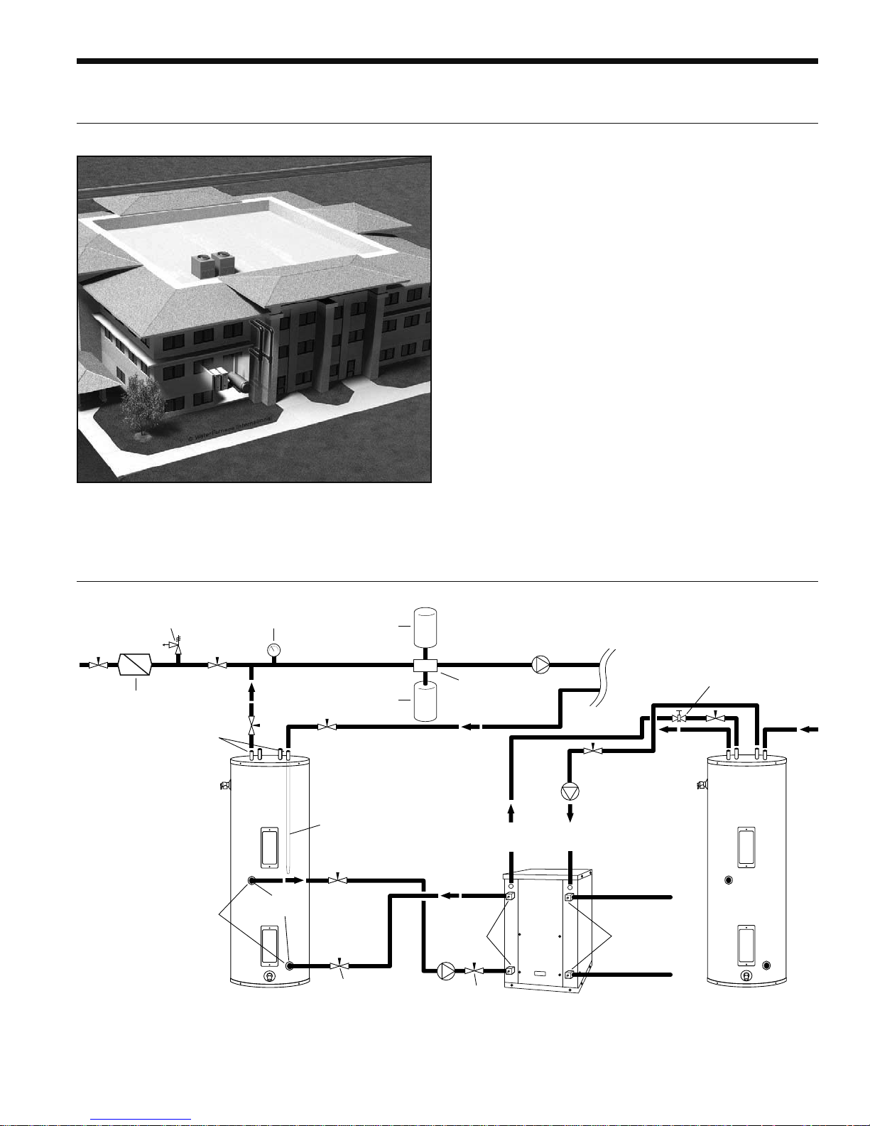
Surface Water - Closed Loop/Ground Source
Plate Heat Exchanger - Closed Loop/Ground Water
• Closed Loop/Ground Water Plate Heat Exchanger
Systems utilize lake, ocean, well water or other water
sources to maintain closed loop water temperatures in
multi-unit systems. A plate frame heat exchanger isolates
the units from any contaminating effects of the water
source, and allows periodic cleaning of the heat exchanger
during off peak hours.
Operation and benefits are similar to those for groundsource systems. Due to the extended loop temperatures,
AHRI/ISO 13256-1 Ground Loop Heat Pumps are required
for this application. Closed loop plate heat exchanger
systems are applicable in commercial, marine, or industrial
structures where the many benefits of a water source heat
pump system are desired, regardless of whether the load is
heating or cooling dominated.
• Closed Loop/Ground-Source Surface Water Systems also
utilize the stable temperatures of Surface Water to maintain
proper water source temperatures for our extended
range heat pump systems. These systems have all of the
advantages of horizontal and vertical closed loop systems.
Due to the extended loop temperatures, AHRI/ISO 13256-1
Ground Water or Ground Loop Heat Pumps are required for
this application.
In cooling dominated structures, the ground-source surface
water systems can be very cost effective especially where
local building codes require water retention ponds for
short term storage of surface run-off. Sizing requirements
for the surface water is a minimum of 500 sq. ft./ton of
surface area at a minimum depth of 8 feet. Your sales
representative should be contacted when designs for
heating dominated structures are required.
14
Page 15
Application Notes cont.
RH SERIES ENGINEERING GUIDE
Cooler/Boiler - Closed Loop
• Closed Loop /Cooler-Boiler Systems utilize a closed heat
recovering loop with multiple water source heat pumps
in the more conventional manner. Typically a boiler is
employed to maintain closed loop temperatures above
60°F and a cooling tower to maintain loop temperatures
below 90°F. These systems are applicable in medium
to large buildings regardless of whether the load is
heating or cooling dominated. Due to the moderate loop
temperatures, AHRI/ISO 13256-1 Water Loop Heat Pumps
are required for this application.
Typical Application Piping
30 psi
RELIEF VALVE
Back Flow Preventer /
Pressure Relief Valve
Dielectric
Unions
Dielectric
Unions
NOTES:
* A 30 psi pressure relief valve (Part No: SRV30) should be used in
hydronic applications.
** Vent valve or P/T port at highest point in return line prior to ball valve.
Pressure
Gauge
GEO
STORAGE
TANK
1-1/2 in.
FPT
Dip Tube
Ball Valve
Expansion
Tank
Air
Vent
Air
Separator
Ball Valve
LOAD PUMP
FROM
HWG
5 Series
Hydronic Unit
TO
HWG
HYDRONIC
PUMP
Source OUT
P/T PortsP/T Ports
Source IN
LOAD
HOT
(Piped in
series to
an electric
water heater)
Vent Valve/
P/T Port**
DOMESTIC
COLD
15
Page 16
RH SERIES ENGINEERING GUIDE
Application Notes cont.
Heating with hot water is versatile because there are many
ways of distributing the heat through the building. The
options range from heavy cast iron radiators seen in older
buildings to modern, baseboard-style convection radiation,
and from invisible radiant floor heating to forced air
systems using fan coil units.
A boiler is often used to make domestic hot water and to
heat swimming pools or hot tubs.
The various distribution systems have all been used
successfully with a geothermal heat pump system. When
designing or retrofitting an existing hydronic heating
system, however, the water temperature produced by the
heat pump is a major consideration.
In general, heat pumps are not designed to produce water
above 130°F. The efficiency decreases as the temperature
difference (
loop) and the supply water (to the distribution system)
increases. Figure 1 illustrates the effect of source and load
temperatures on the system. The heating capacity of the heat
pump also decreases as the temperature difference increases.
When using the various types of hydronic heat distribution
systems, the temperature limits of the geothermal system
must be considered. In new construction, the distribution
system can easily be designed with the temperature limits in
mind. In retrofits, care must be taken to address the operating
temperature limits of the existing distribution system.
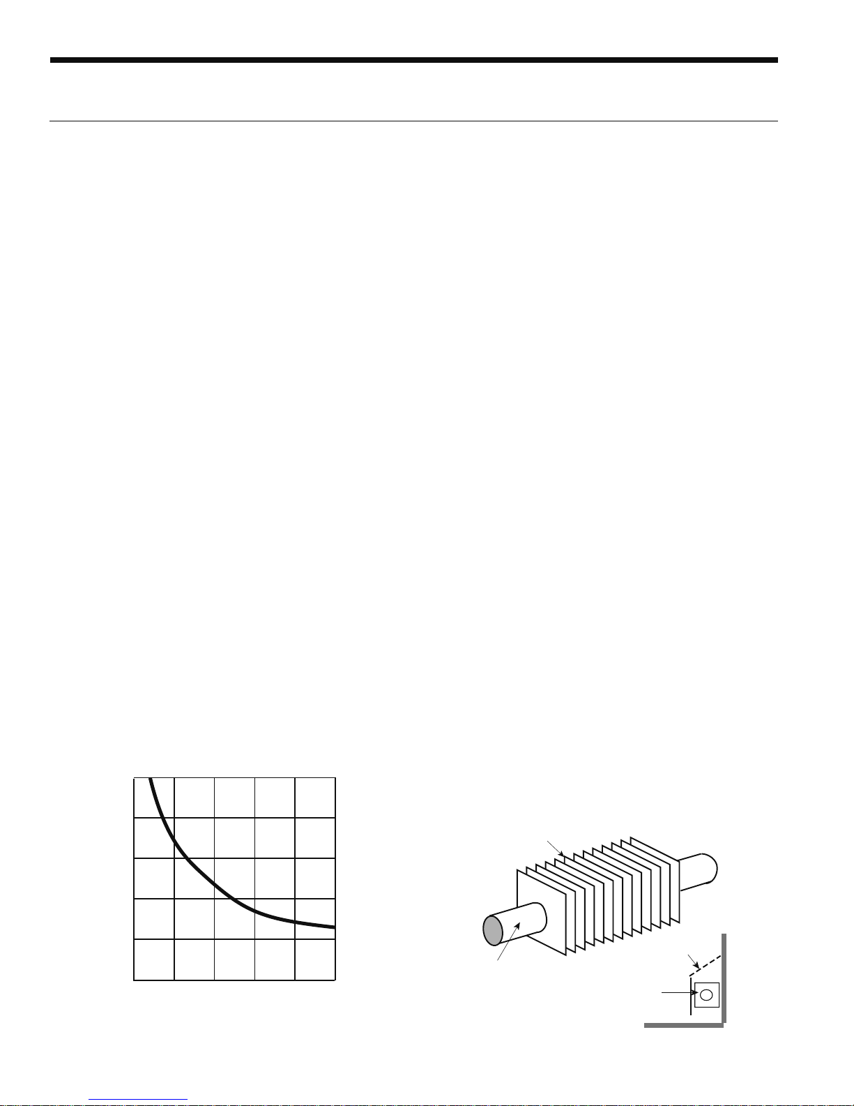
Figure 1: As the
Performance (COP) decreases. When the system produces
130°F water from a 30°F earth loop, the
the COP is approximately 2.5. If the system is producing
water at 90°F, the
3.8, an increase of over 50%.
ΔT) between the heat load (generally the earth
ΔT increases, the Coefficient of
ΔT is 100°F, and
ΔT is 60°F and the COP rises to about
10
8
6
COP
4
Baseboard Radiation
In existing systems, baseboard radiation is typically
designed to operate with 160° to 240°F water or steam.
Baseboard units are typically copper pipe with aluminum
fins along the length of the pipe, as shown in Figure 2. A
decorative cover is normally fitted over the fin tube.
The operation of a baseboard radiation system depends on
setting up a convection current in the room: air is warmed
by the fin tube, rises and is displaced by cool air.
The heating capacity of a baseboard system is a factor of
the area of copper tube and fins exposed to the air and
the temperature difference between the air and the fin
tube. The velocity and volume of water flowing through
the baseboard affects the temperature of the copper and
fins. Baseboard units are normally rated in heat output/
length of baseboard at a standard water temperature and
flow. Manufacturers can provide charts which will give the
capacities at temperatures and flows below the standard.
Figure 3 shows approximate heating capacities for fin tube
radiation using water from 100° to 130°F water.
Baseboards are available using two or three fin tubes tiered
above one another in the same cabinet. With the additional
surface area, the air can be heated enough to set up a
convection current with water temperatures as low as 110°
to 130°F (see Figure 3).
It is important to ensure that the heat output of the system is
adequate to meet the heat loss of the room or building at the
temperatures the geothermal system is capable of producing.
Baseboard radiation is limited to space heating. Cooling is
typically provided by a separate, forced air distribution system.
Figure 2: Baseboard radiators are typically constructed of
copper tube with closely spaced aluminum fins attached
to provide more surface area to dissipate heat. Some of
the factors affecting the amount of heat given off by fin
tube radiators are the water temperature, water velocity, air
temperature, and fin spacing and size.
/Zc[W\c[4W\a
2
0
0 20 40 60 80 100
Temperature Difference (°F)
3\QZ]ac`S
1]^^S` BcPS
4W\BcPS
16
Page 17

Application Notes cont.
RH SERIES ENGINEERING GUIDE
The heating capacity (Btuh/linear foot) of baseboard
radiators drop as the water temperature is reduced. The
heating capacity of most baseboard radiators is rated using
200°F water, 65°F air temperature. Listed in Figure 3 is the
range of heating capacities of baseboard radiators at the
standard temperatures and the range of capacities when
the temperatures are reduced to the operating range of
a heat pump system. Some of the factors that effect the
capacity of a radiator are:
• Size of the fins - range from 2.75 in. x 3 in. to 4 in. x 4 in.
• Fin spacing - 24 to 48 foot
• Diameter of copper tube - range from .75 in. to 2 in.
• Fin material - aluminum or steel
• Configuration and height of the enclosure
• Height unit is mounted from the floor
• Water flow through the radiator
Generally, the smaller fins with fewer fins/foot will have
lower heating capacity. Larger copper tube diameter and
aluminum fins will have a higher capacity. Higher water flow
will increase capacity. Adding a second fin tube to the same
enclosure will increase the capacity by 50 to 60%. Adding
two fin tubes will increase the capacity by 75 to 80%.
Figure 3: Heating output per linear foot
Average
Water Temp.
°
F
110
120°F
°
F
130
Entering Air Temperatures
55°F 65°F 70°F
190-380
240-480
295-590
160-320
205-410
265-532
150-300
195-390
245-490
Cast Iron Radiation
Retrofit applications for hydronic/geothermal heat pump
systems are often required to work with existing cast iron
radiators or their replacements (see Figure 4). Typically,
cast iron radiator systems operate with water temperatures
of 125° to 160°F.
These temperatures are higher than geothermal waterto-water heat pumps are capable of providing. Cast iron
radiators can work with geothermal systems, provided the
heat output of the radiators will meet the maximum heat
loss of the building at the lower temperatures.
If the insulation of the building has been upgraded since
the original installation, it is possible that the lower
temperatures will be able to meet the reduced heat loss of
the building.
Figure 4: Baseboard System
AbSSZ
@ORWOb]`
6]b
EObS`
@ORWOb]`aW\dO`W]ca
Q]\TWUc`ObW]\aO\RaWhSa
Radiant Floor Heating
Radiant floor heating has been the system of choice in
many parts of Europe for some time. Manufacturers have
developed tubing designed for installation in concrete
floors and raised wood floors.
Floor heating systems have several benefits in residential,
commercial and industrial heating applications. In a
building with a radiant floor heating system, the entire floor
acts as a heat source for the room. People feel comfortable
with lower air temperatures if their feet are warm. Typically
the space will feel comfortable with air temperatures as low
as 65°F. Since the heat loss of a building is directly related
to the temperature difference (
outside, a lower
Air temperatures in a room with a forced air heating system
tend to be warmer nearer to the ceiling than the floor (see
Figure 5). The hot air rises and creates a greater pressure
imbalance between the inside and outside. The infiltration
increases, resulting in a higher heat loss. Air temperatures
in a room with radiant floor heating tend to be warmer at
the floor than the ceiling, helping to cut down on infiltration
in the building. The energy savings in a building with
radiant floor heating can range from 10 to 20%.
Figure 5: Temperature Comparison
ΔT means the heat loss is lower.
10° 10°
90°
85°
95°
100°
79°
68°
63°
ΔT) between the inside and
95°
74°
59°
60°
60°
65° 65° 65°
81° 81° 81°
60°
Forced Air System Radiant Floor Heat
17
Page 18

RH SERIES ENGINEERING GUIDE
Application Notes cont.
A floor heat system can be designed to heat a building with
water temperatures as low as 90°F.
Figure 1 shows how a geothermal system operates more
efficiently with a lower
the load. With only a 60°F temperature difference, a
geothermal heat pump will operate at COPs over 4, about
20% higher than a forced air geothermal system in the
same installation.
Some of the factors affecting the heating capacity of a
floor heating system are as follows:
• The type of finish flooring
• The spacing of the pipe
• The water flow through the pipe
• The temperature of the supply water
• The floor material (wood, concrete or poured Gypcrete™)
• Insulation value under the floor
• The piping layout
The spacing of the pipe in residential applications can
vary from 4 in. to 12 in. If the spacing is too large, the
temperature of the floor can vary noticeably. In industrial
applications, variation in the floor temperature is not as
important, and the spacing is related directly to the heat
output required.
Radiant floor heating systems work well with geothermal
heat pump systems. For efficient operation, the system must
be designed with the lowest possible water temperatures.
There are some drawbacks with a radiant floor heating
system. Air conditioning is only possible by adding a
second system using forced air. This can add substantial
cost to an installation where air conditioning is also needed.
A separate air handling system is needed to clean the air or
to introduce fresh air.
Industrial buildings, especially those with high ceilings and
large overhead doors, have an advantage with a radiant
floor heating system. Heat is stored in the concrete floor,
and when a door is opened, the stored heat is immediately
released to the space. The larger the
the space and the floor, the quicker the floor releases its
heat to the space.
Maintenance garages benefit from radiant floor heating
systems. Cold vehicles brought into the garage are warmed
from underneath. The snow melts off the vehicle and dries
much more quickly than when heated from above.
ΔT between the source and
ΔT between the air in
Some pipe manufacturers include an oxygen diffusion
barrier in the pipe to prevent oxygen diffusion through the
pipe. Good system design and careful installation, however,
will eliminate virtually all of the problems encountered
with air in the system. Like earth loop design, it is important
to design the system to facilitate flushing the air initially
and ensuring that the flows can be balanced properly.
Fan Coil Units and Air Handlers
Fan coil units, air handlers, force flow units, etc. are all
basically a hot water radiator or coil (usually copper piping
with aluminum fins) with a fan or blower to move the
air over the coil (see Figure 6). The term “fan coil units”
typically applies to smaller units that are installed in the
zone or area in which heating (or cooling) is needed. They
are available in many different configurations, sizes and
capacities. Fan coil units are designed to be connected to
a ductwork system and can be used to replace a forced air
furnace. Other units are designed for use without ductwork
and are mounted in a suspended ceiling space with only
a grill showing in place of a ceiling tile. Some can be
mounted on a wall under a window, projecting 8 in. to 10
in. into the room or even flush to the wall surface, mounted
between wall studs. Some are available with or without
finished, decorative cabinets. For industrial applications,
inexpensive “unit heaters” are available, with only a coil and
an axial fan. Fan coil units and unit heaters are normally
available with air handling capacities of 200 to 2,000 cfm.
The term “air handler” normally applies to larger units,
mounted in mechanical rooms, mechanical crawl spaces
or rooftops. They typically have an air handling capacity
of over 2,000 cfm and are available for capacities of up to
50,000 cfm. Air handlers are typically built for a specific
installation and are available with many different types of
heating and cooling coils. They can include additional coils
for heating make-up air, dehumidification and exhaust air
heat recovery.
Fan coils and air handlers typically have one or two coils
and a blower. Air is heated by hot water circulated through
the hot water coil. Chilled water is circulated through the
coil if air conditioning is needed. Blowers can be provided
to fit various applications, with or without duct-work.
Unit heaters typically use axial fans in applications where
ductwork is not needed.
Fan coil units and air handlers are used in many different
applications. They have been used to heat buildings
using water temperatures as low as 90° to 100°F. New
systems can be designed to operate very efficiently with a
geothermal system.
18
Page 19

Application Notes cont.
RH SERIES ENGINEERING GUIDE
Figure 6: Fan Coils
0Z]eS`
1VWZZSREObS`1]WZ
6]bEObS`1]WZ
Cooling with a Hydronic System
Cooling a building with an existing radiant hydronic heating
system can be a challenge. If baseboard, cast iron radiators
or a radiant floor heating system is cooled lower than the
dew point, condensation will form on the floor or drip off
the radiators.
There is generally minimal or no ductwork for ventilation
in existing buildings with radiant hydronic heat. Typically,
cooling is provided with separate units where it is needed.
This is often done using through-the-wall or window
air conditioners, ductless split air conditioning units, or
rooftop units.
Controls
The control of a mechanical system determines how
it functions. For the building to work efficiently and
comfortably, the building owner or manager must
understand what the system is doing and how to control it.
As Figure 1 shows, the efficiency of a heat pump is a factor
of the difference in temperature between the source and
the load. The heat loss or heat gain of a building varies with
the weather and the use of the building. As the outdoor
temperature decreases, the heat loss of the building
increases. When the ventilation system is started up,
the heating or cooling loads increase. As the occupancy
increases, lighting or the solar gain increases, and the
cooling load increases. At times the building may require
virtually no heating or cooling.
With hydronic heating and cooling distribution equipment,
whether it is baseboard radiation, fan coil units or
radiant floor heating, the output of the equipment is
directly related to the temperature and velocity of the
water flowing through it. Baseboard radiation puts out
approximately 50% less heat with 110°F water than with
130°F water. The same is true with fan coil units and radiant
floor heating.
A water-to-water heat pump system can provide water to
ducted or unducted fan coil units. The system can provide
chilled water to cool the building, as well as hot water for
the heating system when needed.
A limited amount of cooling can be done by circulating
chilled water through the piping in the floor. This can be
effective in buildings with high solar loads or lighting
loads, where much of the heat gain is radiant heat being
absorbed by the floor. Cooling fresh air used for ventilation
as it is brought into the building, using a chilled water coil,
can sometimes provide the additional cooling needed. Care
must be taken to avoid cooling the floor below the dew
point because condensation may form on the floor.
Buildings with fan coil units and air handlers can generally
be easily retrofitted for cooling. Often it is simply a matter
of adding a cooling coil to the existing air handlers and
fan coil units. Water-to-water heat pumps can provide hot
water for the heating coils as well as chilled water for the
air conditioning.
If a system is designed to meet the maximum heat loss of
a building with 130°F water, it follows that if the heat loss
is 50% lower when the outdoor temperature is higher and
the building has high internal gains because of lighting and
occupancy, the lower heat loss can be met with 110°F water.
This greatly increases the COP of the heat pumps.
The same control strategy is equally effective in cooling.
During peak loads, water chilled to 40°F may be needed;
at other times 55°F water will provide adequate cooling.
Significant increases in the EER can be achieved. Latent
loads must always be considered when using warmer water.
19
Page 20

RH SERIES ENGINEERING GUIDE
Dimensional Data
A
C
Model
018
025
040
050
060 &
075
S
N
R
HWG
Out
I
E
Load
Water
FPT
L
D
Source
Water
FPT
M
HWG
Water
FPT
B
Z
Y
Overall Cabinet Water Connections
ABCDE FGH I
Depth Height Width
in. 23.5 26.1 19.5 10.0 22.2 10.0 22.2 - - 1 in. 1 in. - 16.0 14.2 14.2
cm. 59.7 66.3 49.5 25.4 56.4 25.4 56.4 - - 25.4 mm 25.4 mm - 4 0.6 36.1 36.1
in. 23.5 26.1 19.5 10.0 22.2 10.0 22.2 - - 1 in. 1 in. - 16.0 14.2 14.2
cm. 59.7 66.3 49.5 25.4 56.4 25.4 56.4 - - 25.4 mm 25.4 mm - 4 0.6 36.1 36.1
in. 31.0 26.2 22.0 2.1 19.6 2.1 19.6 23.9 23.9 1 in. 1 in. 1/2 in. 17.1 14.8 17.1
cm. 78.7 66.5 55.9 5.3 49.8 5.3 49.8 60.7 60.7 25.4 mm 25.4 mm 12.7 mm 43.4 37.6 43.4
in. 31.0 26.2 22.0 2.2 20.6 2.2 20.6 23.9 23.9 1-1/4 in. 1-1/4 in. 1/2 in. 17.1 14.8 17.1
cm. 78.7 66.5 55.9 5.6 52.3 5.6 52.3 60.7 60.7 31.8 mm 31.8 mm 12.7 mm 43.4 37.6 43.4
in. 31.0 26.2 22.0 2.4 23.0 2.4 23.0 20.6 20.6 1-1/4 in. 1-1/4 in. 1/2 in. 17.1 14.8 17.1
cm. 78.7 66.5 55.9 6.1 58.4 6.1 58.4 52.3 52.3 31.8 mm 31.8 mm 12.7 mm 43.4 37.6 43.4
W
X
Load
Liquid
Load
Source
Liquid
In
Out
Liquid
In
Source
Liquid
Out
HWG In
U
V
T
Q
P
H
G
J
K
F
O
2/15/16
Electrical Knockouts
JKL
1/2 in.
Voltage
cond
Low
3/4 in.
cond
Ext
Pump
3/4 in.
cond
Power
Supply
Model
018
025
040
050
060 &
075
MNOP QR S TUVWXYZ
Load
Liquid In
in. 2.4 2.4 2.4 2.4 - - 3.5 2.9 14.9 2.6 2.1 1.8 2.9 4.1
cm. 6.1 6.1 6.1 6.1 - - 8.9 7.4 37.8 6.6 5.3 4.4 7.4 10.4
in. 2.4 2.4 2.4 2.4 - - 3.5 2.9 14.9 2.6 2.1 1.8 2.9 4.1
cm. 6.1 6.1 6.1 6.1 - - 8.9 7.4 37.8 6.6 5.3 4.4 7.4 10.4
in. 1.6 2.8 2.8 1.6 2.0 1.8 4.8 4.8 17.1 2.8 14.9 4.8 4.8 17.1
cm. 4.1 7.0 7.0 4.1 5.1 4.6 12.2 12.2 43.4 7.0 37.8 12.2 12.2 43.4
in. 1.8 3.6 3.6 1.8 2.1 1.8 4.8 4.8 17.1 2.8 14.9 4.8 4.8 17.1
cm. 4.6 9.1 9.1 4.6 5.3 4.6 12.2 12.2 43.4 7.1 37.8 12.2 12.2 43.4
in. 1.8 4.0 4.0 1.8 4.2 1.4 4.8 4.8 17.1 2.8 14.9 4.8 4.8 17.1
cm. 4.6 10.2 10.2 4.6 10.7 3.6 12.2 12.2 43.4 7.1 37.8 12.2 12.2 43.4
Load
Liquid
Out
Source
Liquid In
Source
Liquid
Out
Water Connections Electrical Knockouts
HWG In
HWG
Out
Power
Supply
Low
Voltage
Side
Power
Supply
Side
Power
Supply
Ext
Pump
Ext
Pump
Power
Supply
20
Power
Supply
8/6/10
Page 21

RH SERIES ENGINEERING GUIDE
Physical Data
Model 018 025 040 050 060 075
Compressor (1 each) Scroll
Factory Charge R410a, oz [kg] 44.0 [1.25] 58.0 [1.64] 70 [1.98] 68 [1.93] 104 [2.95] 110 [3.12]
Coax & Piping Water Volume - gal [l]* .52 [1.97] .89 [3.38] 1.0 [3.94] 1.4 [5.25] 1.6 [6.13] 1.6 [6.13]
Weight - Operating, lb [kg] 191 [86.6] 225 [102.1] 290 [131.5] 325 [147.4] 345 [156.5] 345 [156.5]
Weight - Packaged, lb [kg] 213 [96.6] 247 [112.0] 305 [138.3] 340 [154.2] 360 [163.3] 360 [163.3]
NOTE: * Source or load side only.
8/6/10
Electrical Data
Unit
Model
018
025
040
050
060
075
Notes: All fuses type "D" time delay (or HACR circuit breaker in USA). 1/15/2015
Source pump amps shown are for up to a 1/2 HP pump
Load pump amps shown are for small circulators.
*LRA with IntelliStart installed.
Rated Voltage Voltage
Min/Max
208-230/60/1 187/253 9.0 48.0 17.0 1.8 5.4 16.2 18.5 25
208-230/60/1 187/253 14.1 73.0 21.4 1.8 5.4 21.3 24.8 35
265/60/1 239/292 11.2 60.0 n/a - - 11.2 14.0 25
460/60/3 414/506 4.2 28.0 16.8 - - 4.2 5.3 6
208-230/60/1 187/253 20.0 115.0 40.3 1.8 5.4 27.2 32.2 50
208-230/60/3 187/253 12.8 95.0 57.0 - - 12.8 16.0 25
460/60/3 414/506 6.4 45.0 27.0 - - 6.4 8.0 10
575/60/3 518/632 5.4 38.0 n/a - - 5.4 6.8 10
208-230/60/1 187/253 26.4 134.0 46.9 1.8 5.4 33.6 40.2 60
265/60/1 239/292 19.9 130.0 n/a - - 19.9 24.9 40
208-230/60/3 187/253 16.0 110.0 66.0 - - 16.0 20.0 35
460/60/3 414/506 7.8 52.0 31.2 - - 7.8 9.8 15
575/60/3 518/632 5.7 38.9 n/a - - 5.7 7.1 10
208-230/60/1 187/253 30.1 145.0 50.8 1.8 5.4 37.3 44.8 70
208-230/60/3 187/253 17.3 120.0 72.0 - - 17.3 21.6 35
460/60/3 414/506 9.6 70.0 42.0 - - 9.6 12.0 20
575/60/3 518/632 8.0 53.0 n/a - - 8.0 10.0 15
208-230/60/1 187/253 26.9 145.0 50.8 1.8 5.4 34.1 40.8 60
208-230/60/3 187/253 22.4 190.0 114.0 - - 22.4 28.0 50
460/60/3 414/506 12.2 87.0 52.2 - - 12.2 15.3 25
575/60/3 518/632 9.6 62.0 n/a - - 9.6 12.0 20
Compressor Load
RLA LRA LRA*
Pump
Source
Pump
Total
Unit FLA
Min Ckt
Amp
Maximum
Fuse/HACR
21
Page 22

RH SERIES ENGINEERING GUIDE
Antifreeze Correction
Catalog performance can be corrected for antifreeze use. Please use the following table and note the example given.
Antifreeze Type
EWT - °F [°C]
Wat er
Ethylene Glycol
Propylene Glycol
Ethanol
Methanol
WARNING: Gray area represents antifreeze concentrations greater than 35% by weight and should
be avoided due to the extreme performance penalty they represent.
Antifreeze %
by wt
0 1.000 1.000 1.000 1.000 1.000
10 0.990 0.973 0.976 0.991 1.075
20 0.978 0.943 0.947 0.979 1.163
30 0.964 0.917 0.921 0.965 1.225
40 0.953 0.890 0.897 0.955 1.324
50 0.942 0.865 0.872 0.943 1.419
10 0.981 0.958 0.959 0.981 1.130
20 0.967 0.913 0.921 0.969 1.270
30 0.946 0.854 0.869 0.950 1.433
40 0.932 0.813 0.834 0.937 1.614
50 0.915 0.770 0.796 0.922 1.816
10 0.986 0.927 0.945 0.991 1.242
20 0.967 0.887 0.906 0.972 1.343
30 0.944 0.856 0.869 0.947 1.383
40 0.926 0.815 0.830 0.930 1.523
50 0.907 0.779 0.795 0.911 1.639
10 0.985 0.957 0.962 0.986 1.127
20 0.969 0.924 0.929 0.970 1.197
30 0.950 0.895 0.897 0.951 1.235
40 0.935 0.863 0.866 0.936 1.323
50 0.919 0.833 0.836 0.920 1.399
Heating Cooling
Load Source Load Source
80 [26.7] 30 [-1.1] 50 [10.0] 90 [32.2] 30 [-1.1]
Pressure
Drop
Antifreeze Correction Example
Antifreeze solution is propylene glycol 20% by weight for the source and methanol 10% for the load. Determine the
corrected heating at 30°F source and 80°F load as well as pressure drop at 30°F for an 050. Also, determine the corrected
cooling at 90°F source and 50°F load.
The corrected heating capacity at 30°F/80°F would be:
46,700 MBTUH x 0.913 x 0.985 = 41,998 MBTUH
The corrected cooling capacity at 90°F/50°F would be:
44,200 x 0.969 x 0.962 = 41,202 MBTUH
The corrected pressure drop at 30°F and 15 GPM would be:
5.2 psi x 1.270 = 6.60 psi
22
Page 23

AHRI/ISO 13256-2 Performance Ratings
English (IP) Units
Water Loop Heat Pump Ground Water Heat Pump
Flow Rate
Load
Gpm
Flow Rate
Load
Gpm
Source
Gpm
Source
Gpm
018
025
075
018
025
075
Capacity
Modulation
Single 5 5 16,400 14.0 22,200 4.5 18,800 22.9 18,500 3.7 Yes
Single 7 7 23,700 13.6 32,800 4.6 26,700 21.2 27,100 3.8 Yes
Single 10 10 35,900 15.5 47,900 4.8 40,900 23.4 39,100 3.9 Yes
Single 15 15 49,800 13.9 65,000 4.4 55,600 21.6 54,200 3.7 Yes
Single 18 18 55,400 13.6 78,000 4.7 62,500 20.6 63,200 3.8 Yes
Single 19 19 66,000 12.3 93,100 4.2 74,100 18.0 77,100 3.5 No
Capacity
Modulation
Single 5 5 17,300 16.6 14,700 3.1 Yes
Single 7 7 24,700 16.1 22,000 3.1 Yes
Single 10 10 37,700 17.5 30,500 3.1 Yes
Single 15 15 51,500 16.4 44,200 3.1 Yes
Single 18 18 58,000 16.1 50,100 3.1 Yes
Single 19 19 68,400 14.0 61,500 2.9 No
Model
040
050
060
Model
040
050
060
NOTE: All ratings based upon 208V operation.
Cooling
86°F Source
53.6°F Load
Capacity
Btuh
77°F Source
53.6°F Load
Capacity
Btuh
EER
Btuh/W
Ground Loop Heat Pump
Cooling
EER Btuh/W
Heating
68°F Source
104°F Load
Capacity
Btuh
Capacity
Btuh
COP
Heating
32°F Source
104°F Load
COP
Cooling
59°F Source
53.6°F Load
Capacity
Btuh
RH SERIES ENGINEERING GUIDE
Heating
50°F Source
104°F Load
EER
Btuh/W
Energy
Star
Compliant
01/03/12
Capacity
Btuh
COP
Energy
Star
Compliant
23
Page 24

RH SERIES ENGINEERING GUIDE
Pressure Drop
Model GPM
3.0 0.5 0.4 0.4 0.3 0.3
018R*
025R*
040H/R
050H/R
060H/R
075H/R
NOTES: Temperatures are Entering Water Temperatures
4.0 1.1 0.9 0.9 0.8 0.8
5.0 1.6 1.4 1.4 1.3 1.3
6.0 2.1 1.9 1.9 1.8 1.8
4.0 0.7 0.6 0.4 0.3 0.3
5.0 0.9 0.6 0.6 0.5 0.5
10.0 3.7 3.5 3.3 3.2 3.0
12.5 5.0 4.7 4.4 4.2 4.0
8.0 1.7 1.4 1.4 1.3 1.3
11.5 3.6 3.4 3.2 3.0 2.8
15.0 5.6 5.4 5.0 4.6 4.2
18.5 8.3 8.1 7.6 7.2 6.8
9.0 1.4 1.1 1.0 1.0 0.9
13.5 4.2 3.9 3.5 3.1 2.7
18.0 6.9 6.7 6.0 5.2 4.5
22.5 10.7 10.5 10.0 9.4 8.7
10.0 3.2 3.0 2.8 2.7 2.5
14.5 5.5 5.3 5.1 4.9 4.7
19.0 7.9 7.6 7.3 7.1 6.8
23.5 11.5 11.3 11.0 10.8 10.5
*Domestic water heating units source side
pressure drop and reversible units load and
source pressure drop.
30°F 60°F 80°F 100°F 120°F
5.5 1.3 1.1 0.9 0.7 0.6
7.0 1.9 1.7 1.5 1.3 1.2
8.5 2.6 2.4 2.2 2.0 1.9
7.5 2.3 2.1 2.0 1.9 1.8
Pressure Drop (psi)
8/9/10
Vented Only Load Side
Model GPM
3.0 0.5 0.4 0.4 0.3
018H
025H
NOTES: Temperatures are Entering Water Temperatures.
Double wall vented coax for heating potable water
4.0 1.4 1.3 1.2 1.2
5.0 2.2 2.1 2.1 2.0
6.0 3.0 2.9 2.9 2.8
4.0 1.3 1.3 1.2 1.2
5.5 3.0 2.9 2.8 2.7
7.0 4.6 4.4 4.3 4.1
8.5 6.7 6.5 6.4 6.2
60°F 80°F 100°F 120°F
Pressure Drop (psi)
7/13/09
24
Page 25

Reference Calculations
RH SERIES ENGINEERING GUIDE
Heating Calculations:
LWT = EWT - HE
GPM x C*
HE = C* x GPM x (EWT - LWT) HR = C* x GPM x (LWT - EWT)
NOTE: * C = 500 for pure water, 485 for brine.
Cooling Calculations:
LWT = EWT + HR
GPM x C*
Legend and Notes
Abbreviations and Definitions
ELT = entering load fluid temperature to heat pump kW = kilowatts
SWPD = source coax water pressure drop EST = entering source fluid temperature to heat pump
LLT = leaving load fluid temperature from heat pump HE = heat extracted in MBTUH
PSI = pressure drop in pounds per square inch LST = leaving source fluid temperature from heat pump
LGPM = load flow in gallons per minute HC = total heating capacity in MBTUH
FT HD = pressure drop in feet of head COP = coefficient of performance, heating [HC/kW x 3.413]
LWPD = load coax water pressure drop EER = energy efficiency ratio, cooling
LWT = leaving water temperature TC = total cooling capacity in MBTUH
EWT = entering water temperature HR = heat rejected in MBTUH
Brine = water with a freeze inhibiting solution
Notes to Performance Data Tables
The following notes apply to all performance data tables:
• Three flow rates are shown for each unit. The lowest flow rate shown is used for geothermal open loop/well water
systems with a minimum of 50°F EST. The middle flow rate shown is the minimum geothermal closed loop flow rate.
The highest flow rate shown is optimum for geothermal closed loop systems and the suggested flow rate for boiler/
tower applications.
• Entering water temperatures below 40°F assumes 15% antifreeze solution.
• Interpolation between ELT, EST, and GPM data is permissible.
• Operation in the gray areas is not recommended.
25
Page 26

RH SERIES ENGINEERING GUIDE
018 - Performance Data
Cooling Capacity
Source Load Flow-3 GPM Load Flow-4 GPM Load Flow-5 GPM
EST°FFlow
30
50
70
90
110
ELT°FLLT°FTC
GPM
50 37.8 17.8 0.60 19.8 29.7 43.6 40.1 18.1 0.61 20.1 29.8 43.8 42.5 18.3 0.61 20.4 30.0 44.0
70 56.8 19.3 0.59 21.3 32.5 44.6 59.3 19.4 0.60 21.5 32.6 44.8 61.9 19.6 0.60 21.6 32.7 44.9
3
90 75.8 20.7 0.59 22.7 35.3 45.6 78.6 20.8 0.59 22.8 35.4 45.7 81.4 20.9 0.59 22.9 35.4 45.7
110 94.7 22.2 0.58 24.2 38.3 46.6 97.8 22.2 0.58 24.2 38.3 46.6 100.8 22.2 0.58 24.2 38.3 46.6
50 37.7 18.0 0.58 19.9 30.9 40.9 40.0 18.2 0.58 20.2 31.2 41.1 42.4 18.4 0.59 20.4 31.5 41.2
70 56.7 19.3 0.57 21.3 33.8 41.7 59.3 19.5 0.57 21.4 34.0 41.8 61.9 19.6 0.58 21.6 34.1 41.9
4
90 75.8 20.7 0.56 22.6 36.7 42.4 78.6 20.8 0.56 22.7 36.8 42.5 81.4 20.9 0.57 22.8 36.9 42.5
110 94.9 22.0 0.56 23.9 39.6 43.2 97.9 22.1 0.56 23.9 39.7 43.2 100.9 22.1 0.56 24.0 39.8 43.2
50 37.6 18.1 0.56 20.0 32.3 38.3 40.0 18.3 0.56 20.2 32.7 38.3 42.4 18.5 0.56 20.4 33.0 38.4
70 56.7 19.3 0.55 21.2 35.2 38.7 59.3 19.5 0.55 21.4 35.5 38.8 61.9 19.7 0.55 21.5 35.8 38.9
5
90 75.9 20.6 0.54 22.4 38.1 39.2 78.6 20.7 0.54 22.5 38.3 39.3 81.4 20.8 0.54 22.7 38.6 39.4
110 95.0 21.8 0.53 23.6 41.1 39.7 98.0 21.9 0.53 23.7 41.3 39.8 100.9 22.0 0.53 23.8 41.5 39.8
50 38.4 16.9 0.80 19.6 22.9 63.4 40.5 17.3 0.80 20.0 23.3 63.8 42.7 17.8 0.80 20.5 23.7 64.1
70 56.3 19.9 0.80 22.6 26.5 65.5 58.9 20.2 0.80 22.9 26.8 65.8 61.5 20.6 0.80 23.3 27.2 66.0
3
90 74.3 22.9 0.80 25.6 30.1 67.6 77.3 23.1 0.79 25.8 30.4 67.8 80.4 23.4 0.79 26.1 30.7 67.9
110 92.2 25.9 0.80 28.6 33.8 69.7 95.7 26.1 0.79 28.8 34.0 69.8 99.2 26.2 0.79 28.9 34.2 69.9
50 38.3 17.0 0.77 19.6 22.0 60.8 40.5 17.4 0.77 20.0 22.6 61.0 42.6 17.8 0.77 20.5 23.1 61.2
70 56.3 19.9 0.77 22.5 26.0 62.4 58.9 20.3 0.76 22.9 26.5 62.6 61.5 20.6 0.76 23.2 27.0 62.8
4
90 74.3 22.9 0.76 25.5 30.2 64.0 77.3 23.1 0.76 25.7 30.5 64.2 80.4 23.4 0.76 25.9 30.9 64.3
110 92.2 25.9 0.75 28.4 34.4 65.7 95.7 26.0 0.75 28.6 34.6 65.7 99.2 26.1 0.75 28.7 34.8 65.8
50 38.2 17.1 0.75 19.7 24.7 58.1 40.4 17.5 0.75 20.0 25.3 58.3 42.6 17.9 0.74 20.4 25.9 58.4
70 56.3 20.0 0.74 22.5 28.8 59.3 58.9 20.3 0.73 22.8 29.2 59.4 61.5 20.6 0.73 23 .1 29.7 59.5
5
90 74.3 22.9 0.72 25.4 33.0 60.5 77.3 23.1 0.72 25.6 33.3 60.5 80.4 23.3 0.72 25.8 33.6 60.6
110 92.3 25.8 0.71 28.2 37.3 61.6 95.8 25.9 0.71 28.3 37.5 61.7 99.3 26.1 0.71 28.5 37.7 61.7
50 39.1 15.9 0.99 19.3 16.1 83.3 41.0 16.6 0.99 19.9 16.7 83.7 42.9 17.2 0.99 20.6 17.4 84.1
70 55.9 20.5 1.00 23.9 20.5 86.4 58.5 21.0 1.00 24.4 21.1 86.8 61.1 21.5 0.99 24.9 21.7 87.1
3
90
110
50 39.0 16.0 0.97 19.3 16.6 80.6 40.9 16.6 0.96 19.9 17.3 80.9 42.9 17.3 0.96 20.5 18.1 81.3
70 55.9 20.6 0.96 23.8 21.4 83.1 58.5 21.1 0.96 24.3 22.0 83.4 61.1 21.6 0.95 24.8 22.6 83.7
4
90
110
50 38.9 16.1 0.94 19.3 17.1 78.0 40.9 16.7 0.93 19.9 18.0 78.2 42.9 17.3 0.92 20.4 18.8 78.4
70 55.8 20.7 0.92 23.8 22.4 79.8 58.5 21.1 0.92 24.2 23.0 80.0 61.1 21.6 0.91 24.7 23.7 80.2
5
90
110
50 40.4 14.0 1.30 18.4 11.8 102.7 42.1 14.5 1.30 19.0 12.3 103.0 43.8 15.1 1.30 19.5 12.7 103.4
70 57.4 18.3 1.30 22.7 15.3 105.6 59.8 18.7 1.30 23.2 15.7 105.9 62.1 19.2 1.30 23.6 16.1 106.2
3
90
110
50 40.3 14.1 1.27 18.4 11.2 100.1 42.0 14.6 1.26 19.0 11.6 100.4 43.8 15.2 1.26 19.5 12.0 100.7
70 57.3 18.4 1.26 22.7 14.6 102.5 59.7 18.9 1.26 23.1 15.0 102.7 62.0 19.3 1.26 23.6 15.4 103.0
4
90
110
50 40.2 14.3 1.24 18.5 12.6 97.6 42.0 14.8 1.23 18.9 13.2 97.8 43.7 15.3 1.23 19.4 13.7 98.0
70 57.2 18.6 1.22 22.7 16.6 99.4 59.6 19.0 1.21 23.1 17.1 99.5 62.0 19.4 1.21 23.5 17.5 99.7
5
90
110
50 41.7 12.1 1.60 17.6 7.6 122.1 43.2 12.5 1.61 18.0 7.8 122.4 44.7 12.9 1.61 18.4 8.0 122.6
70 59.0 16.1 1.60 21.5 10.0 124.8 61.0 16.5 1.60 21.9 10.3 125.1 63.1 16.8 1.61 22.3 10.5 125.3
3
90
110
50 41.6 12.3 1.57 17.6 7.8 119.7 43.1 12.7 1.57 18.0 8.1 119.9 44.6 13.1 1.57 18.4 8.3 120.1
70 58.8 16.3 1.56 21.6 10.5 121.9 60.9 16.6 1.56 22.0 10.7 122.1 63.0 17.0 1.56 22.3 10.9 122.3
4
90
110
50 41.5 12.4 1.53 17.6 8.1 117.3 43.0 12.8 1.53 18.0 8.4 117.4 44.6 13.2 1.53 18.4 8.6 117.6
70 58.7 16.5 1.51 21.6 10.9 118.9 60.8 16.8 1.51 22.0 11.1 119.1 62.9 17.2 1.51 22.4 11.4 119.2
5
90
110
MBTUH
PowerkWHR
MBTUH
EER
LST°FLLT°FTC
MBTUH
PowerkWHR
MBTUH
Operation not recommended
Operation not recommended
ation not recommended
Oper
Operation not recommended
Operation not recommended
Operation not recommended
Operation not recommended
Operation not recommended
Operation not recommended
EER
LST°FLLT°FTC
MBTUH
PowerkWHR
MBTUH
EER
LST
°F
8/20/09
26
Page 27

RH SERIES ENGINEERING GUIDE
018 - Performance Data cont.
Heating Capacity
Source Load Flow-3 GPM Load Flow-4 GPM Load Flow-5 GPM
EST°FFlow
25
30
50
70
90
ELT°FLLT°FHC
GPM
60
80
4
100
120
60 69.8 14.2 0.90 11.1 4.62 20.4 67.4 14.3 0.88 11.3 4.76 20.3 65.9 14.4 0.86 11.5 4.91 20.3
80 89.4 13.7 1.21 9.6 3.31 21.1 87.1 13.8 1.19 9.7 3.38 21.0 85.7 13.9 1.17 9.9 3.46 20.9
5
100 109.1 13.2 1.53 8.0 2.53 21.7 106.8 13.3 1.51 8.1 2.58 21.6 105.5 13.3 1.49 8.3 2.63 21.6
120 128.7 12.7 1.84 6.4 2.02 22.4 126.6 12.8 1.82 6.5 2.05 22.3 125.3 12.8 1.80 6.7 2.08 22.3
60 70.4 15.1 0.91 12.0 4.86 21.8 68.3 15.2 0.90 12.1 4.96 21.7 66.3 15.2 0.88 12.2 5.06 21.6
80 90.0 14.5 1.22 10.4 3.48 22.9 88.0 14.6 1.21 10.5 3.55 22.8 86.0 14.6 1.19 10.6 3.61 22.7
3
100 109.6 14.0 1.54 8.7 2.66 24.0 107.7 14.0 1.52 8.8 2.71 23.9 105.8 14.1 1.49 9.0 2.76 23.8
120 129.2 13.4 1.85 7.1 2.12 25.1 127.4 13.5 1.83 7.2 2.16 25.0 125.6 13.5 1.80 7.4 2.20 24.9
60 70.7 15.5 0.91 12.4 5.02 23.2 68.6 15.6 0.89 12.6 5.14 23.2 66.5 15.7 0.88 12.7 5.26 23.1
80 90.2 14.9 1.22 10.7 3.58 24.2 88.2 15.0 1.20 10.9 3.66 24.1 86.2 15.0 1.18 11.0 3.75 24.0
4
100 109.8 14.3 1.53 9.0 2.73 25.1 107.9 14.3 1.50 9.2 2.79 25.0 105.9 14.4 1.48 9.3 2.85 24.9
120 129.4 13.7 1.85 7.4 2.17 26.0 127.5 13.7 1.81 7.5 2.21 25.9 125.6 13.7 1.78 7.6 2.26 25.8
60 70.9 15.9 0.90 12.8 5.18 24.7 68.8 16.1 0.89 13.0 5.32 24.6 66.7 16.2 0.87 13.2 5.46 24.5
80 90.5 15.2 1.21 11.1 3.68 25.4 88.4 15.3 1.19 11.3 3.78 25.3 86.4 15.4 1.16 11.5 3.89 25.3
5
100 110.0 14.6 1.53 9.4 2.80 26.1 108.0 14.6 1.49 9.5 2.87 26.1 106.0 14.7 1.46 9.7 2.95 26.0
120 129.6 13.9 1.84 7.6 2.21 26.9 127.6 13.9 1.80 7.8 2.27 26.8 125.7 13.9 1.75 7.9 2.33 26.7
60 73.5 19.7 0.90 16.6 6.46 38.6 70.9 19.8 2.74 10.4 4.71 42.8 68.2 20.0 4.59 4.3 2.97 47.1
80 93.0 18.9 1.21 14.7 4.58 39.9 90.4 19.0 2.43 10.7 3.48 42.7 87.9 19.1 3.65 6.6 2.37 45.4
3
100 112.4 18.1 1.52 12.9 3.48 41.2 110.0 18.1 2.12 10.9 2.85 42.5 107.5 18.2 2.71 9.0 2.21 43.8
120 131.9 17.3 1.84 11.0 2.76 42.4 129.5 17.3 1.80 11.1 2.82 42.3 127.2 17.4 1.77 11.3 2.88 42.2
60 73.9 20.2 0.89 17.1 6.62 40.7 71.2 20.4 1.81 14.2 3.31 42.7 68.5 20.6 2.72 11.3 2.22 44.8
80 93.3 19.3 1.21 15.2 4.69 41.7 90.7 19.5 1.80 13.3 3.16 43.0 88.1 19.6 2.40 11.4 2.40 44.4
4
100 112.7 18.4 1.52 13.2 3.55 42.8 110.2 18.5 1.80 12.4 3.02 43.4 107.7 18.6 2.08 11.5 2.63 44.0
120 132.1 17.6 1.83 11.3 2.81 43.8 129.7 17.6 1.80 11.5 2.87 43.7 127.3 17.7 1.76 11.7 2.94 43.6
60 74.2 20.7 0.89 17.7 6.83 42.7 71.5 21.0 0.87 18.0 7.12 42.6 68.7 21.2 0.85 18.3 7.41 42.4
80 93.6 19.8 1.20 15.6 4.82 43.5 90.9 19.9 1.17 15.9 4.99 43.4 88.3 20.1 1.15 16.2 5.17 43.3
5
100 112.9 18.8 1.52 13.6 3.64 44.4 110.4 18.9 1.48 13.9 3.75 44.3 107.8 19.0 1.45 14.1 3.87 44.2
120 132.3 17.9 1.83 11.6 2.86 45.2 129.8 17.9 1.79 11.8 2.94 45.1 127.4 18.0 1.75 12.0 3.02 45.1
60 76.6 24.2 0.88 21.2 8.06 55.4 73.4 24.5 4.59 8.8 4.46 64.0 70.2 24.7 8.30 -3.6 0.87 72.5
80 95.9 23.2 1.19 19.1 5.69 56.9 92.8 23.4 3.65 10.9 3.41 62.5 89.7 23.5 6.11 2.7 1.13 68.2
3
100 115.2 22.1 1.51 17.0 4.30 58.3 112.2 22.3 2.72 13.0 2.99 61.1 109.2 22.4 3.93 9.0 1.67 63.8
120 134.5 21.1 1.82 14.9 3.40 59.8 131.6 21.2 1.78 15.1 3.48 59.6 128.7 21.2 1.74 15.3 3.57 59.5
60 77.1 24.9 0.88 21.8 8.27 58.1 73.8 25.2 2.72 15.9 2.71 62.2 70.5 25.5 4.56 9.9 1.64 66.4
80 96.3 23.7 1.19 19.6 5.82 59.3 93.1 23.9 2.41 15.7 2.91 62.0 90.0 24.2 3.62 11.8 1.96 64.8
4
100 115.5 22.6 1.51 17.4 4.39 60.5 112.5 22.7 2.09 15.6 3.18 61.8 109.4 22.9 2.68 13.7 2.50 63.1
120 134.7 21.5 1.82 15.2 3.45 61.7 131.8 21.5 1.78 15.4 3.54 61.6 128.9 21.6 1.74 15.7 3.64 61.4
60 77.5 25.5 0.88 22.5 8.49 60.7 74.2 25.9 0.85 22.9 8.93 60.5 70.8 26.2 0.82 23.4 9.36 60.3
80 96.7 24.3 1.19 20.2 5.96 61.7 93.5 24.5 1.16 20.6 6.20 61.5 90.2 24.8 1.13 21.0 6.45 61.4
5
100 115.8 23.0 1.51 17.9 4.48 62.6 112.7 23.2 1.47 18.2 4.63 62.5 109.6 23.4 1.43 18.5 4.78 62.4
120 135.0 21.8 1.82 15.6 3.51 63.6 132.0 21.9 1.78 15.8 3.61 63.5 129.1 22.0 1.74 16.1 3.70 63.4
79.6 28.5 0.88 25.5 9.49 72.5 75.6 28.4 0.85 25.5 9.84 72.5 71.6 28.2 0.81 25.4 10.20 72.5
60
80 98.6 27.1 1.18 23.0 6.70 74.2 94.9 27.1 1.15 23.1 6.92 74.1 91.1 27.0 1.11 23.2 7.14 74.0
3
100
120
60 80.1 29.2 0.88 26.2 9.72 75.7 76.0 29.0 0.85 26.1 10.05 75.7 71.9 28.8 0.81 26.0 10.40 75.8
80 99.0 27.7 1.19 23.6 6.84 77.1 95.2 27.6 1.15 23.7 7.05 77.0 91.4 27.6 1.11 23.8 7.28 77.0
4
100
120
60 80.5 29.9 0.88 26.9 9.96 78.9 76.3 29.6 0.85 26.7 10.28 79.0 72.1 29.3 0.81 26.5 10.60 79.1
80 99.4 28.2 1.19 24.2 6.97 80.0 95.5 28.2 1.15 24.2 7.19 80.0 91.6 28.1 1.11 24.3 7.42 80.0
5
100
120
MBTUH
PowerkWHE
MBTUH
LST°FLLT°FHC
COP
PowerkWHE
MBTUH
Operation not recommended
Operation not recommended
Operation not recommended
Operation not recommended
MBTUH
LST°FLLT°FHC
COP
MBTUH
PowerkWHE
MBTUH
COP
LST
°F
8/19/09
27
Page 28

RH SERIES ENGINEERING GUIDE
018 DHW - Performance Data cont.
Heating Only Capacity
Source Load Flow-3 GPM Load Flow-4 GPM Load Flow-5 GPM
EST°FFlow
25
30
50
70
90
ELT°FLLT°FHC
GPM
60
80
4
100
120
60 70.0 14.5 0.97 11.2 4.38 20.4 67.6 14.7 0.95 11.4 4.52 20.3 66.1 14.8 0.93 11.6 4.66 20.2
80 89.7 14.1 1.30 9.7 3.19 21.0 87.4 14.3 1.28 9.9 3.27 20.9 85.9 14.4 1.26 10.1 3.36 20.8
5
100 109.5 13.8 1.62 8.2 2.48 21.6 107.2 13.9 1.60 8.4 2.54 21.5 105.8 14.0 1.58 8.6 2.59 21.5
120 129.2 13.4 1.95 6.7 2.01 22.2 127.0 13.5 1.93 6.9 2.05 22.1 125.6 13.6 1.91 7.1 2.09 22.1
60 70.4 15.2 0.97 11.9 4.59 21.8 68.4 15.4 0.95 12.1 4.74 21.7 66.4 15.5 0.93 12.3 4.88 21.5
80 90.2 14.9 1.30 10.4 3.35 22.8 88.2 15.0 1.28 10.6 3.43 22.7 86.2 15.1 1.26 10.8 3.52 22.6
3
100 110.0 14.5 1.63 9.0 2.61 23.8 108.0 14.7 1.61 9.2 2.67 23.7 106.1 14.8 1.59 9.3 2.72 23.6
120 129.8 14.2 1.96 7.5 2.12 24.8 127.8 14.3 1.94 7.7 2.16 24.7 125.9 14.4 1.92 7.8 2.20 24.6
60 70.7 15.6 0.97 12.3 4.71 23.3 68.6 15.8 0.95 12.5 4.86 23.2 66.6 15.9 0.93 12.7 5.01 23.1
80 90.4 15.2 1.30 10.8 3.43 24.1 88.4 15.3 1.28 11.0 3.51 24.0 86.4 15.5 1.26 11.2 3.60 23.9
4
100 110.2 14.8 1.63 9.2 2.66 25.0 108.2 14.9 1.61 9.4 2.71 24.9 106.2 15.0 1.59 9.6 2.77 24.8
120 129.9 14.4 1.96 7.7 2.15 25.8 127.9 14.5 1.94 7.9 2.19 25.7 126.0 14.6 1.92 8.0 2.23 25.6
60 71.0 16.0 0.97 12.7 4.83 24.8 68.9 16.2 0.95 12.9 4.98 24.7 66.7 16.3 0.93 13.1 5.14 24.6
80 90.7 15.5 1.30 11.1 3.50 25.4 88.6 15.7 1.28 11.3 3.59 25.3 86.5 15.8 1.26 11.5 3.68 25.3
5
100 110.4 15.1 1.63 9.5 2.71 26.1 108.3 15.2 1.61 9.7 2.76 26.0 106.3 15.2 1.58 9.8 2.82 25.9
120 130.0 14.6 1.96 7.9 2.18 26.7 128.0 14.7 1.94 8.0 2.22 26.7 126.1 14.7 1.91 8.2 2.26 26.6
60 73.4 19.6 0.98 16.2 5.87 38.9 70.8 19.8 0.95 16.5 6.10 38.7 68.2 20.0 0.93 16.8 6.33 38.5
80 93.0 18.9 1.31 14.4 4.23 40.1 90.5 19.1 1.28 14.7 4.37 39.9 87.9 19.3 1.25 15.0 4.51 39.7
3
100 112.5 18.3 1.64 12.7 3.26 41.3 110.1 18.4 1.61 12.9 3.35 41.1 107.6 18.6 1.58 13.2 3.44 41.0
120 132.1 17.6 1.97 10.9 2.62 42.5 129.7 17.7 1.94 11.1 2.68 42.4 127.4 17.9 1.91 11.3 2.74 42.2
60 73.8 20.1 0.98 16.7 6.03 40.9 71.1 20.3 0.95 17.0 6.26 40.7 68.5 20.5 0.93 17.3 6.49 40.5
80 93.3 19.4 1.31 14.9 4.34 41.9 90.7 19.5 1.28 15.2 4.47 41.7 88.1 19.7 1.25 15.4 4.61 41.6
4
100 112.8 18.6 1.64 13.0 3.33 42.9 110.3 18.8 1.61 13.3 3.41 42.8 107.8 18.9 1.58 13.5 3.50 42.6
120 132.3 17.9 1.97 11.2 2.66 43.9 129.9 18.0 1.94 11.4 2.72 43.8 127.5 18.1 1.91 11.6 2.78 43.7
60 74.2 20.6 0.98 17.3 6.18 42.9 71.4 20.8 0.95 17.6 6.43 42.7 68.7 21.1 0.93 17.9 6.68 42.6
80 93.6 19.8 1.31 15.3 4.44 43.7 91.0 20.0 1.28 15.6 4.58 43.6 88.3 20.1 1.25 15.9 4.72 43.5
5
100 113.1 19.0 1.64 13.4 3.39 44.5 110.5 19.1 1.61 13.6 3.48 44.4 107.9 19.2 1.58 13.8 3.57 44.3
120 132.5 18.2 1.97 11.5 2.70 45.3 130.0 18.3 1.94 11.6 2.76 45.2 127.5 18.3 1.91 11.8 2.82 45.1
60 76.4 23.9 0.98 20.6 7.15 55.9 73.2 24.2 0.95 20.9 7.46 55.6 70.1 24.4 0.92 21.3 7.77 55.4
80 95.8 22.9 1.31 18.5 5.12 57.3 92.7 23.2 1.28 18.8 5.30 57.1 89.6 23.4 1.25 19.1 5.49 56.9
3
100 115.1 22.0 1.65 16.3 3.91 58.8 112.2 22.2 1.61 16.7 4.03 58.6 109.2 22.3 1.57 17.0 4.16 58.3
120 134.4 21.0 1.98 14.2 3.11 60.2 131.6 21.2 1.94 14.5 3.20 60.0 128.8 21.3 1.90 14.8 3.28 59.8
60 76.9 24.6 0.98 21.2 7.34 58.4 73.6 24.8 0.95 21.6 7.66 58.2 70.4 25.1 0.92 22.0 7.99 58.0
80 96.2 23.5 1.31 19.0 5.24 59.6 93.0 23.7 1.28 19.3 5.43 59.4 89.9 23.9 1.25 19.7 5.62 59.3
4
100 115.4 22.5 1.65 16.8 3.99 60.8 112.4 22.6 1.61 17.1 4.11 60.7 109.4 22.8 1.57 17.4 4.24 60.5
120 134.7 21.4 1.98 14.6 3.17 62.0 131.8 21.5 1.94 14.9 3.25 61.9 128.9 21.6 1.90 15.1 3.33 61.7
60 77.3 25.2 0.98 21.9 7.53 61.0 74.0 25.5 0.95 22.3 7.88 60.8 70.6 25.8 0.92 22.7 8.22 60.7
80 96.5 24.1 1.31 19.6 5.37 61.9 93.3 24.3 1.28 19.9 5.56 61.8 90.1 24.5 1.25 20.2 5.76 61.7
5
100 115.8 22.9 1.65 17.3 4.08 62.9 112.7 23.1 1.61 17.6 4.20 62.8 109.6 23.2 1.57 17.8 4.32 62.6
120 135.0 21.8 1.98 15.0 3.23 63.8 132.0 21.9 1.94 15.2 3.30 63.7 129.0 21.9 1.90 15.4 3.38 63.6
79.2 28.0 0.98 24.7 8.37 73.1 79.3 28.2 0.95 24.9 8.69 72.9 79.5 28.3 0.92 25.2 9.01 72.7
60
80 98.2 26.5 1.31 22.0 5.93 74.9 98.4 26.7 1.27 22.4 6.16 74.6 98.5 27.0 1.24 22.7 6.39 74.4
3
100
120
60
80
4
100
120
60
80
5
100
120
MBTUH
PowerkWHE
MBTUH
LST°FLLT°FHC
COP
PowerkWHE
MBTUH
Operation not recommended
Operation not recommended
MBTUH
LST°FLLT°FHC
COP
MBTUH
PowerkWHE
MBTUH
COP
LST
°F
10/28/09
28
Page 29

RH SERIES ENGINEERING GUIDE
025 - Performance Data
Cooling Capacity
Source Load Flow-4 GPM Load Flow-5.5 GPM Load Flow-7 GPM
EST°FFlow
30
50
70
90
110
ELT°FLLT°FTC
GPM
50 36.6 25.9 0.96 29.2 27.0 45.0 39.3 26.7 0.96 30.0 27.8 45.5 41.9 27.5 0.96 30.8 28.6 45.9
70 55.5 28.0 0.96 31.3 29.2 46.1 58.5 28.6 0.96 31.8 29.7 46.4 61.4 29.1 0.96 32.3 30.3 46.7
4
90 74.5 30.2 0.96 33.4 31.4 47.2 77.7 30.4 0.96 33.7 31.7 47.4 81.0 30.6 0.96 33.9 31.9 47.5
110 93.4 32.3 0.96 35.6 33.6 48.3 96.9 32.3 0.96 35.5 33.6 48.3 100.5 32.2 0.96 35.5 33.5 48.3
50 36.9 25.4 0.93 28.6 27.3 41.6 39.5 26.2 0.93 29.3 28.1 41.9 42.1 26.9 0.93 30.1 28.9 42.3
70 56.0 27.1 0.93 30.3 29.2 42.4 58.9 27.6 0.93 30.7 29.7 42.6 61.7 28.1 0.93 31.2 30.2 42.8
5.5
90 75.2 28.8 0.93 31.9 31.0 43.1 78.3 29.0 0.93 32.2 31.3 43.2 81.4 29.2 0.93 32.4 31.5 43.3
110 94.3 30.5 0.93 33.6 32.9 43.8 97.7 30.4 0.93 33.6 32.9 43.8 101.0 30.4 0.93 33.6 32.9 43.8
50 37.2 24.9 0.90 28.0 27.7 38.2 39.7 25.6 0.90 28.7 28.4 38.4 42.3 26.3 0.90 29.4 29.2 38.7
70 56.5 26.1 0.90 29.2 29.1 38.6 59.3 26.6 0.90 29.7 29.7 38.7 62.0 27.1 0.90 30.1 30.2 38.9
7
90 75.9 27.4 0.89 30.4 30.6 39.0 78.8 27.6 0.89 30.6 30.9 39.0 81.8 27.8 0.89 30.9 31.2 39.1
110 95.3 28.6 0.89 31.6 32.1 39.3 98.4 28.6 0.89 31.6 32.1 39.3 101.6 28.6 0.89 31.6 32.1 39.3
50 37.3 24.6 1.24 28.8 21.2 64.8 39.8 25.4 1.24 29.6 21.8 65.2 42.3 26.2 1.24 30.4 22.5 65.7
70 55.4 28.3 1.25 32.6 24.0 66.8 58.3 29.0 1.25 33.3 24.5 67.2 61.2 29.7 1.25 34.0 25.0 67.5
4
90 73.4 32.1 1.26 36.4 26.7 68.8 76.8 32.7 1.26 37.0 27.1 69.1 80.2 33.3 1.26 37.6 27.5 69.4
110 91.5 35.9 1.27 40.2 29.4 70.7 95.3 36.4 1.27 40.7 29.7 71.0 99.1 36.9 1.27 41.2 29.9 71.3
50 37.5 24.3 1.20 28.4 20.3 61.5 39.9 25.1 1.20 29.2 21.0 61.9 42.4 25.9 1.20 30.0 21.6 62.2
70 55.7 27.8 1.20 31.9 23.1 63.0 58.5 28.5 1.20 32.6 23.7 63.3 61.4 29.2 1.20 33.3 24.3 63.6
5.5
90 73.9 31.3 1.21 35.4 25.9 64.4 77.2 31.8 1.21 35.9 26.4 64.7 80.5 32.4 1.21 36.5 26.8 64.9
110 92.1 34.7 1.21 38.9 28.7 65.9 95.8 35.2 1.21 39.3 29.1 66.1 99.5 35.7 1.21 39.8 29.4 66.3
50 37.6 24.1 1.16 28.0 22.0 58.3 40.0 24.9 1.16 28.8 22.8 58.5 42.4 25.7 1.16 29.6 23.5 58.7
70 56.0 27.2 1.16 31.2 24.5 59.2 58.8 27.9 1.16 31.9 25.1 59.4 61.6 28.6 1.16 32.5 25.8 59.6
7
90 74.3 30.4 1.16 34.3 27.1 60.1 77.5 30.9 1.16 34.9 27.5 60.3 80.7 31.5 1.16 35.4 28.0 60.4
110 92.7 33.6 1.16 37.5 29.6 61.0 96.3 34. 0 1 .16 3 7.9 29 .9 61 .2 9 9.9 34.4 1.16 38.3 30.2 61.3
50 38.0 23.2 1.51 28.4 15.4 84.6 40.4 24.0 1.52 29.2 15.8 85.0 42.7 24.8 1.52 30.0 16.3 85.5
70 55.2 28.6 1.53 33.9 18.7 87.5 58.1 29.5 1.54 34.8 19.2 87.9 61.0 30.4 1.54 35.7 19.7 88.4
4
90 72.4 34.1 1.55 39.4 22.0 90.3 75.9 35.0 1.56 40.3 22.5 90.8 79.4 36.0 1.56 41.3 23.1 91.3
110 Operation not recommended
50 38.0 23.2 1.47 28.2 15.8 81.4 40.3 24.1 1.47 29.1 16.4 81.8 42.7 25.0 1.47 30.0 17.0 82.1
70 55.3 28.5 1.48 33.5 19.3 83.6 58.2 29.4 1.48 34.4 19.9 84.0 61.1 30.3 1.48 35.3 20.5 84.3
5.5
90 72.6 33.7 1.49 38.8 22.7 85.8 76.1 34.7 1.49 39.7 23.3 86.2 79.5 35.6 1.49 40.7 23.9 86.5
110 Operation not recommended
50 38.0 23.2 1.42 28.0 16.3 78.3 40.3 24.2 1.42 29.0 17.1 78.5 42.6 25.1 1.41 29.9 17.8 78.8
70 55.4 28.3 1.42 33.1 19.9 79.8 58.3 29.2 1.42 34.1 20.6 80.0 61.1 30.1 1.41 35.0 21.3 80.3
7
90 72.8 33.4 1.42 38.2 23.5 81.3 76.2 34.3 1.42 39.1 24.2 81.5 79.6 35.2 1.42 40.0 24.8 81.8
110 90.2 38.5 1.42 43.3 27.1 82.8 94.2 39.4 1.42 44.2 27.7 83.0 98.2 40.2 1.42 45.0 28.3 83.3
50 39.3 20.9 1.93 27.4 11.6 104.1 41.4 21.5 1.94 28.1 12.0 104.5 43.5 22.2 1.94 28.8 12.3 104.9
70 56.3 26.6 1.96 33.3 14.5 107.2 59.0 27.4 1.97 34.1 14.9 107.6 61.7 28.3 1.97 35.0 15.3 108.0
4
90
110
50 39.2 20.9 1.88 27.3 11.1 101.1 41.3 21.6 1.88 28.0 11.5 101.4 43.4 22.4 1.88 28.8 11.9 101.7
70 56.3 26.7 1.89 33.1 14.1 103.4 59.0 27.5 1.90 34.0 14.5 103.8 61.7 28.3 1.90 34.8 14.9 104.1
5.5
90
110
50 39.2 21.0 1.83 27.2 12.3 98.0 41.3 21.7 1.83 28.0 12.8 98.2 43.4 22.5 1.83 28.7 13.3 98.5
70 56.2 26.8 1.83 33.0 15.6 99.7 58.9 27.6 1.83 33.8 16.1 100.0 61.6 28.4 1.83 34.6 16.6 100.2
7
90
110
50 40.5 18.5 2.35 26.5 7.9 123.7 42.3 19.1 2.36 27.1 8.1 124.0 44.2 19.6 2.36 27.7 8.3 124.3
70 57.3 24.6 2.39 32.7 10.3 126.9 59.8 25.4 2.40 33.5 10.6 127.3 62.3 26.2 2.40 34.4 10.9 127.7
4
90
110
50 40.4 18.6 2.30 26.4 8.1 120.7 42.3 19.2 2.30 27.0 8.3 120.9 44.2 19.8 2.30 27.6 8.6 121.2
70 57.2 24.9 2.31 32.8 10.8 123.3 59.7 25.6 2.32 33.5 11.1 123.6 62.2 26.4 2.32 34.3 11.4 123.9
5.5
90
110
50 40.4 18.7 2.24 26.3 8.3 117.8 42.2 19.3 2.24 26.9 8.6 117.9 44.1 19.9 2.24 27.5 8.9 118.1
70 57.0 25.2 2.24 32.8 11.3 119.7 59.6 25.9 2.24 33.5 11.6 119.9 62.2 26.6 2.24 34.2 11.9 120.1
7
90
110
MBTUH
PowerkWHR
MBTUH
EER
LST°FLLT°FTC
MBTUH
PowerkWHR
MBTUH
ation not recommended
Oper
Operation not recommended
Operation not recommended
Operation not recommended
Operation not recommended
Operation not recommended
EER
LST°FLLT°FTC
MBTUH
PowerkWHR
MBTUH
EER
LST
°F
8/20/09
29
Page 30

RH SERIES ENGINEERING GUIDE
025 - Performance Data cont.
Heating Capacity
Source Load Flow-4 GPM Load Flow-5.5 GPM Load Flow-7 GPM
EST°FFlow
25
30
50
70
90
ELT°FLLT°FHC
GPM
60
80
5.5
100
120
60 71.0 21.4 1.28 17.0 4.90 20.0 68.1 21.5 1.26 17.2 5.02 19.9 66.4 21.6 1.23 17.4 5.15 19.9
80 90.6 20.5 1.70 14.7 3.54 20.7 87.7 20.7 1.67 14.9 3.62 20.6 86.1 20.8 1.65 15.1 3.70 20.5
7
100 110.1 19.7 2.12 12.4 2.72 21.3 107.4 19.8 2.09 12.7 2.77 21.3 105.9 19.9 2.06 12.9 2.83 21.2
120 129.7 18.8 2.54 10.1 2.17 22.0 127.1 19.0 2.51 10.4 2.21 21.9 125.6 19.1 2.48 10.6 2.26 21.9
60 71.4 22.2 1.29 17.8 5.04 20.8 69.1 22.4 1.26 18.1 5.21 20.7 66.7 22.6 1.23 18.4 5.38 20.5
80 91.0 21.4 1.71 15.6 3.67 22.0 88.7 21.6 1.68 15.9 3.78 21.8 86.4 21.8 1.64 16.2 3.88 21.7
4
100 110.6 20.6 2.12 13.4 2.84 23.1 108.4 20.8 2.09 13.6 2.91 23.0 106.2 20.9 2.06 13.9 2.98 22.8
120 130.2 19.8 2.54 11.1 2.28 24.3 128.1 20.0 2.51 11.4 2.33 24.1 125.9 20.1 2.47 11.7 2.38 24.0
60 71.8 22.9 1.29 18.4 5.19 22.6 69.3 23.0 1.26 18.7 5.35 22.5 66.8 23.2 1.23 19.0 5.53 22.4
80 91.3 21.9 1.71 16.1 3.76 23.5 88.9 22.1 1.68 16.4 3.87 23.4 86.6 22.3 1.64 16.7 3.98 23.3
5.5
100 110.8 21.0 2.12 13.7 2.90 24.5 108.6 21.2 2.09 14.1 2.97 24.4 106.3 21.4 2.06 14.4 3.05 24.2
120 130.3 20.1 2.54 11.4 2.31 25.4 128.2 20.3 2.51 11.7 2.37 25.3 126.0 20.5 2.47 12.1 2.43 25.2
60 72.1 23.5 1.29 19.1 5.34 24.4 69.6 23.7 1.26 19.3 5.50 24.3 67.0 23.8 1.23 19.6 5.67 24.2
80 91.6 22.4 1.71 16.6 3.85 25.1 89.1 22.6 1.68 16.9 3.96 25.0 86.7 22.8 1.64 17.2 4.07 24.9
7
100 111.0 21.4 2.12 14.1 2.95 25.8 108.7 21.6 2.09 14.5 3.03 25.7 106.4 21.9 2.06 14.8 3.12 25.6
120 130.5 20.3 2.54 11.6 2.34 26.6 128.3 20.6 2.51 12.1 2.41 26.5 126.2 20.9 2.47 12.5 2.48 26.3
60 75.2 29.4 1.31 24.9 6.55 37.2 71.9 29.5 1.27 25.1 6.79 37.1 68.7 29.5 1.23 25.3 7.03 37.0
80 94.5 28.2 1.74 22.3 4.74 38.5 91.4 28.3 1.69 22.5 4.89 38.4 88.3 28.3 1.65 22.7 5.04 38.3
4
100 113.9 27.0 2.16 19.6 3.65 39.9 111.0 27.1 2.11 19.9 3.75 39.7 108.0 27.2 2.06 20.1 3.85 39.6
120 133.3 25.9 2.59 17.0 2.91 41.2 130.5 25.9 2.54 17.3 2.99 41.1 127.7 26.0 2.48 17.5 3.07 41.0
60 75.7 30.4 1.31 25.9 6.79 39.6 72.3 30.4 1.27 26.1 7.02 39.5 69.0 30.5 1.23 26.3 7.25 39.5
80 95.0 29.1 1.74 23.2 4.90 40.7 91.8 29.1 1.69 23.4 5.04 40.6 88.6 29.2 1.65 23.6 5.19 40.6
5.5
100 114.3 27.7 2.16 20.4 3.76 41.8 111.3 27.8 2.11 20.6 3.86 41.7 108.2 27.9 2.06 20.9 3.96 41.6
120 133.6 26.4 2.59 17.6 2.99 42.9 130.7 26.5 2.54 17.9 3.06 42.8 127.8 26.6 2.48 18.2 3.15 42.7
60 76.2 31.5 1.32 27.0 6.98 42.1 72.7 31.4 1.27 27.1 7.23 42.0 69.2 31.4 1.23 27.2 7.48 42.0
80 95.4 30.0 1.74 24.0 5.02 42.9 92.1 30.0 1.69 24.2 5.18 42.9 88.8 30.0 1.65 24.4 5.34 42.8
7
100 114.7 28.5 2.17 21.1 3.83 43.8 111.5 28.5 2.11 21.3 3.95 43.7 108.4 28.6 2.06 21.6 4.06 43.6
120 133.9 27.0 2.59 18.1 3.04 44.7 131.0 27.1 2.54 18.4 3.13 44.6 128.0 27.3 2.48 18.8 3.22 44.5
60 78.9 36.6 1.33 32.1 8.06 53.5 74.8 36.5 1.28 32.1 8.37 53.4 70.7 36.4 1.23 32.2 8.67 53.4
80 98.1 35.0 1.77 29.0 5.81 55.0 94.2 35.0 1.71 29.1 6.00 55.0 90.3 34.9 1.65 29.3 6.20 54.9
4
100 117.3 33.5 2.20 25.9 4.45 56.6 113.5 33.4 2.14 26.1 4.59 56.5 109.8 33.4 2.07 26.3 4.73 56.4
120 136.4 31.9 2.64 22.9 3.54 58.2 132.9 31.9 2.57 23.1 3.65 58.1 129.4 31.9 2.49 23.4 3.75 57.9
60 79.6 38.0 1.34 33.4 8.34 56.6 75.3 37.9 1.28 33.5 8.65 56.6 71.1 37.7 1.23 33.5 8.98 56.6
80 98.7 36.3 1.77 30.2 6.00 57.9 94.7 36.2 1.71 30.3 6.19 57.9 90.6 36.1 1.65 30.4 6.40 57.8
5.5
100 117.8 34.5 2.21 27.0 4.58 59.2 114.0 34.5 2.14 27.2 4.72 59.1 110.1 34.4 2.07 27.3 4.87 59.0
120 136.9 32.8 2.64 23.7 3.63 60.5 133.3 32.8 2.57 24.0 3.74 60.4 129.6 32.8 2.49 24.3 3.85 60.3
60 80.3 39.4 1.34 34.8 8.61 59.7 75.9 39.2 1.29 34.8 8.95 59.7 71.5 39.0 1.23 34.8 9.29 59.7
80 99.3 37.5 1.77 31.4 6.19 60.7 95.1 37.3 1.71 31.5 6.40 60.7 91.0 37.2 1.65 31.6 6.61 60.7
7
100 118.3 35.5 2.21 28.0 4.72 61.8 114.4 35.5 2.14 28.2 4.86 61.7 110.4 35.4 2.07 28.3 5.01 61.7
120 137.3 33.6 2.64 24.6 3.73 62.8 133.6 33.6 2.57 24.8 3.84 62.7 129.9 33.6 2.49 25.1 3.95 62.6
82.7 44.0 1.37 39.3 9.41 69.7 77.7 43.7 1.31 39.2 9.79 69.8 72.8 43.4 1.25 39.1 10.17 69.8
60
80 101.6 41.9 1.80 35.7 6.80 71.6 96.9 41.7 1.73 35.8 7.07 71.6 92.2 41.5 1.66 35.9 7.33 71.5
4
100
120
60 83.5 45.5 1.38 40.8 9.66 73.6 78.2 44.8 1.32 40.3 9.96 73.8 73.0 44.1 1.26 39.8 10.30 73.9
80 102.3 43.2 1.81 37.0 6.99 75.2 97.4 42.8 1.74 36.8 7.22 75.2 92.5 42.4 1.66 36.7 7.46 75.2
5.5
100
120
60 84.2 47.0 1.39 42.3 9.91 77.6 78.7 45.9 1.33 41.4 10.16 77.8 73.2 44.8 1.26 40.5 10.42 78.1
80 102.9 44.5 1.82 38.3 7.18 78.7 97.8 43.8 1.74 37.9 7.38 78.8 92.7 43.2 1.67 37.5 7.59 79.0
7
100
120
MBTUH
PowerkWHE
MBTUH
LST°FLLT°FHC
COP
PowerkWHE
MBTUH
Operation not recommended
Operation not recommended
Operation not recommended
Operation not recommended
MBTUH
LST°FLLT°FHC
COP
MBTUH
PowerkWHE
MBTUH
COP
LST
°F
8/19/09
30
Page 31

RH SERIES ENGINEERING GUIDE
025 DHW - Performance Data cont.
Heating Only Capacity
Source Load Flow-4 GPM Load Flow-5.5 GPM Load Flow-7 GPM
EST°FFlow
25
30
50
70
90
ELT°FLLT°FHC
GPM
60
80
5.5
100
120
60 71.1 21.6 1.40 16.8 4.52 20.0 68.1 21.7 1.39 17.0 4.59 20.0 66.4 21.8 1.37 17.1 4.66 20.0
80 90.8 20.9 1.84 14.6 3.33 20.7 87.9 21.1 1.79 14.9 3.44 20.6 86.2 21.2 1.74 15.2 3.56 20.5
7
100 110.4 20.3 2.29 12.5 2.60 21.3 107.6 20.4 2.20 12.9 2.72 21.2 106.0 20.5 2.11 13.3 2.85 21.1
120 130.1 19.6 2.73 10.3 2.10 22.0 127.4 19.8 2.61 10.9 2.22 21.8 125.9 19.9 2.48 11.4 2.35 21.6
60 71.7 22.7 1.41 17.9 4.72 20.8 69.2 22.8 1.38 18.0 4.83 20.7 66.7 22.8 1.35 18.2 4.95 20.6
80 91.4 22.1 1.86 15.7 3.48 21.9 89.0 22.1 1.77 16.1 3.67 21.7 86.5 22.2 1.68 16.4 3.87 21.5
4
100 111.0 21.4 2.31 13.5 2.72 23.0 108.7 21.5 2.16 14.1 2.93 22.7 106.3 21.5 2.00 14.7 3.15 22.4
120 130.7 20.8 2.76 11.4 2.21 24.1 128.4 20.9 2.55 12.2 2.42 23.7 126.2 20.9 2.33 12.9 2.63 23.3
60 72.0 23.3 1.42 18.4 4.81 22.6 69.4 23.3 1.38 18.6 4.94 22.5 66.9 23.4 1.35 18.8 5.08 22.5
80 91.6 22.5 1.87 16.2 3.54 23.5 89.1 22.6 1.80 16.5 3.68 23.4 86.7 22.7 1.73 16.8 3.84 23.2
5.5
100 111.2 21.8 2.32 13.9 2.76 24.4 108.9 21.9 2.21 14.3 2.90 24.2 106.5 22.0 2.11 14.8 3.05 24.0
120 130.9 21.1 2.77 11.7 2.24 25.3 128.6 21.2 2.63 12.2 2.36 25.1 126.3 21.3 2.50 12.7 2.50 24.8
60 72.3 23.8 1.42 19.0 4.91 24.4 69.7 23.9 1.39 19.2 5.06 24.4 67.1 24.0 1.35 19.4 5.21 24.3
80 91.9 23.0 1.87 16.6 3.60 25.1 89.3 23.1 1.83 16.9 3.70 25.0 86.8 23.2 1.79 17.1 3.80 25.0
7
100 111.4 22.2 2.32 14.3 2.80 25.8 109.0 22.3 2.27 14.5 2.88 25.7 106.6 22.4 2.22 14.8 2.95 25.6
120 131.0 21.4 2.77 11.9 2.26 26.5 128.7 21.5 2.72 12.2 2.32 26.4 126.4 21.6 2.66 12.5 2.38 26.3
60 75.2 29.5 1.47 24.4 5.85 37.4 71.9 29.5 1.42 24.7 6.06 37.3 68.7 29.6 1.38 24.9 6.27 37.2
80 94.6 28.3 1.92 21.7 4.28 38.8 91.5 28.4 1.84 22.1 4.48 38.6 88.4 28.5 1.77 22.4 4.68 38.4
4
100 114.0 27.1 2.38 19.0 3.32 40.2 111.0 27.2 2.27 19.5 3.50 40.0 108.1 27.4 2.16 20.0 3.68 39.7
120 133.4 25.9 2.84 16.2 2.66 41.6 130.5 26.1 2.69 16.9 2.83 41.3 127.7 26.3 2.55 17.6 2.99 40.9
60 75.6 30.3 1.47 25.3 6.03 39.8 72.3 30.4 1.43 25.5 6.25 39.8 69.0 30.5 1.38 25.7 6.48 39.7
80 95.0 29.0 1.93 22.4 4.41 41.0 91.8 29.1 1.86 22.8 4.58 40.9 88.6 29.2 1.80 23.1 4.77 40.7
5.5
100 114.3 27.7 2.38 19.6 3.41 42.1 111.3 27.9 2.30 20.0 3.55 41.9 108.3 28.0 2.21 20.5 3.71 41.8
120 133.6 26.4 2.84 16.7 2.72 43.3 130.8 26.6 2.74 17.3 2.85 43.0 127.9 26.8 2.63 17.8 2.99 42.8
60 76.1 31.2 1.48 26.1 6.13 42.3 72.7 31.3 1.43 26.4 6.38 42.2 69.2 31.4 1.38 26.6 6.63 42.2
80 95.3 29.8 1.94 23.2 4.48 43.2 92.1 29.9 1.88 23.5 4.64 43.1 88.8 30.0 1.83 23.8 4.80 43.0
7
100 114.6 28.3 2.39 20.2 3.45 44.1 111.5 28.5 2.33 20.6 3.57 43.9 108.5 28.7 2.27 21.0 3.69 43.8
120 133.9 26.9 2.85 17.2 2.76 44.9 131.0 27.2 2.78 17.7 2.85 44.8 128.1 27.4 2.72 18.1 2.95 44.7
60 78.7 36.2 1.52 31.0 6.98 54.0 74.7 36.3 1.46 31.3 7.29 53.9 70.7 36.3 1.40 31.5 7.60 53.8
80 97.8 34.5 1.98 27.7 5.09 55.7 94.0 34.6 1.92 28.1 5.29 55.5 90.2 34.7 1.85 28.4 5.49 55.4
4
100 116.9 32.7 2.45 24.4 3.92 57.4 113.3 33.0 2.38 24.8 4.07 57.2 109.8 33.2 2.31 25.3 4.21 57.0
120 136.0 31.0 2.91 21.1 3.12 59.1 132.6 31.3 2.84 21.6 3.24 58.9 129.3 31.6 2.76 22.2 3.35 58.6
60 79.3 37.4 1.53 32.2 7.16 57.1 75.2 37.5 1.47 32.4 7.48 57.0 71.0 37.5 1.41 32.7 7.82 56.9
80 98.3 35.5 1.99 28.7 5.22 58.5 94.4 35.7 1.93 29.1 5.43 58.3 90.5 35.8 1.86 29.5 5.64 58.2
5.5
100 117.3 33.6 2.45 25.2 4.01 59.9 113.7 33.9 2.38 25.7 4.16 59.7 110.0 34.1 2.31 26.2 4.32 59.5
120 136.3 31.7 2.92 21.8 3.19 61.3 132.9 32.1 2.84 22.4 3.31 61.0 129.5 32.4 2.77 23.0 3.43 60.8
60 79.9 38.6 1.54 33.3 7.34 60.2 75.6 38.7 1.48 33.6 7.69 60.1 71.4 38.7 1.41 33.9 8.04 60.0
80 98.8 36.5 2.00 29.7 5.35 61.2 94.8 36.7 1.93 30.1 5.57 61.1 90.9 36.9 1.86 30.5 5.80 61.0
7
100 117.8 34.5 2.46 26.1 4.11 62.3 114.0 34.8 2.39 26.6 4.27 62.2 110.3 35.0 2.32 27.1 4.43 62.0
120 136.7 32.4 2.92 22.4 3.25 63.4 133.2 32.8 2.85 23.1 3.38 63.2 129.8 33.2 2.77 23.7 3.51 63.0
82.0 42.7 1.56 37.4 8.02 70.7 82.2 43.0 1.49 37.9 8.48 70.5 82.3 43.3 1.42 38.5 8.93 70.2
60
80 100.9 40.5 2.02 33.6 5.86 72.7 101.0 40.8 1.95 34.2 6.15 72.4 101.2 41.1 1.87 34.8 6.44 72.1
4
100
120
60
80
5.5
100
120
60
80
7
100
120
MBTUH
PowerkWHE
MBTUH
LST°FLLT°FHC
COP
PowerkWHE
MBTUH
Operation not recommended
Operation not recommended
MBTUH
LST°FLLT°FHC
COP
MBTUH
PowerkWHE
MBTUH
COP
LST
°F
10/28/09
31
Page 32

RH SERIES ENGINEERING GUIDE
040 - Performance Data
Cooling Capacity
Source Load Flow-5 GPM Load Flow-7.5 GPM Load Flow-10 GPM
EST°FFlow
30
50
70
90
110
ELT°FLLT°FTC
GPM
50 34.0 38.7 1.38 43.4 28.0 47.9 37.8 39.8 1.39 44.5 28.7 48.4 41.6 40.9 1.39 45.6 29.4 48.8
70 54.5 37.5 1.27 41.8 29.4 47.2 58.3 38.0 1.25 42.3 30.4 47.4 62.0 38.6 1.23 42.8 31.4 47.6
5
90 75.1 36.2 1.17 40.2 31.1 46.6 78.8 36.2 1.12 40.0 32.6 46.5 82.5 36.2 1.06 39.9 34.1 46.4
110 95.6 35.0 1.06 38.6 33.0 45.9 99.3 34.5 0.98 37.8 35.3 45.6 103.0 33.9 0.90 37.0 37.7 45.2
50 34.5 37.7 1.32 42.2 28.6 43.2 38.2 38.6 1.33 43.1 29.1 43.5 41.9 39.4 1.33 43.9 29.6 43.8
70 55.1 36.2 1.23 40.4 29.6 42.6 58.7 36.7 1.21 40.8 30.3 42.8 62.3 37.1 1.19 41.2 31.2 42.9
7.5
90 75.7 34.7 1.13 38.6 30.7 42.1 79.3 34.8 1.09 38.5 31.9 42.1 82.8 34.9 1.05 38.5 33.1 42.0
110 96.3 33.2 1.04 36.7 32.1 41.6 99.8 32.9 0.98 36.2 33.7 41.4 103.3 32.6 0.92 35.7 35.6 41.2
50 34.9 36.7 1.26 41.0 29.1 38.5 38.5 37.3 1.27 41.6 29.5 38.6 42.2 37.9 1.27 42.2 29.8 38.7
70 55.6 34.9 1.18 38.9 29.7 38.0 59.1 35.3 1.17 39.3 30.3 38.1 62.6 35.7 1.16 39.6 30.9 38.2
10
90 76.3 33.2 1.09 36.9 30.3 37.6 79.7 33.3 1.07 37.0 31.2 37.6 83.1 33.5 1.04 37.1 32.1 37.6
110 97.1 31.4 1.01 34.8 31.1 37.2 100.3 31.4 0.97 34.7 32.4 37.1 103.5 31.3 0.93 34.5 33.7 37.1
50 35.3 35.7 1.76 41.7 21.6 67.2 38.6 37.4 1.76 43.4 22.6 67.9 41.9 39.2 1.76 45.2 23.5 68.6
70 53.4 40.2 1.73 46.1 24.5 69.0 57.3 41.5 1.72 47.4 25.5 69.5 61.2 42.8 1.71 48.6 26.4 70.1
5
90 71.5 44.8 1.71 50.6 27.4 70.9 76.0 45.6 1.69 51.4 28.5 71.2 80.4 46.4 1.66 52.1 29.5 71.5
110 89.6 49.4 1.68 55.1 30.4 72.7 94.7 49.7 1.65 55.3 31.7 72.8 99.7 50.1 1.62 55.6 33.0 72.9
50 39.1 35.3 1.69 41.0 20.9 62.8 38.8 36.9 1.68 42.6 21.9 63.3 42.1 38.5 1.68 44.2 22.9 63.8
70 57.8 39.2 1.65 44.8 23.7 64.0 58.7 40.3 1.64 45.9 24.5 64.4 61.4 41.5 1.63 47.1 25.4 64.7
7.5
90 76.5 43.0 1.62 48.6 26.5 65.2 77.8 43.8 1.60 49.2 27.3 65.4 80.8 44.5 1.59 49.9 28.1 65.7
110 95.2 46.9 1.59 52.3 29.5 66.5 95.4 47.2 1.56 52.5 30.2 66.5 100.2 47.5 1.54 52.7 30.9 66.6
50 42.8 34.9 1.61 40.4 23.0 58.3 38.9 36.4 1.61 41.9 23.8 58.6 42.2 37.9 1.61 43.3 24.7 58.9
70 62.1 38.1 1.57 43.5 25.3 59.0 60.1 39.1 1.57 44.5 26.1 59.2 61.7 40.2 1.56 45.5 26.9 59.4
10
90 81.5 41.3 1.54 46.5 27.6 59.6 79.6 41.9 1.52 47.1 28.4 59.7 81.2 42.6 1.51 47.7 29.1 59.8
110 100.8 44.5 1.50 49.6 30.0 60.2 96.2 4 4.7 1.48 49.7 30.8 60.3 100.7 44.9 1.46 49.9 31.5 60.3
50 36.6 32.6 2.14 39.9 15.2 86.5 39.4 35.0 2.14 42.3 16.4 87.4 42.3 37.4 2.13 44.7 17.6 88.4
70 52.3 43.0 2.19 50.5 19.6 90.8 56.3 45.0 2.20 52.5 20.5 91.6 60.3 47.0 2.20 54.5 21.4 92.5
5
90 68.0 53.3 2.25 61.0 23.7 95.2 73.2 55.0 2.26 62.7 24.4 95.8 78.3 56.6 2.26 64.3 25.0 96.5
110 Operation not recommended
50 36.5 32.9 2.05 39.8 16.0 82.3 39.4 35.2 2.04 42.2 17.2 83.1 42.2 37.6 2.04 44.5 18.5 83.8
70 56.9 42.1 2.08 49.2 20.2 85.3 58.7 44.0 2.08 51.1 21.2 85.9 60.5 45.9 2.08 52.9 22.1 86.5
7.5
90 73.9 51.4 2.11 58.6 24.3 88.4 76.4 52.7 2.12 59.9 24.9 88.8 78.8 54.1 2.12 61.3 25.5 89.3
110 Operation not recommended
50 36.4 33.1 1.96 39.8 16.9 78.2 39.3 35.5 1.95 42.1 18.2 78.7 42.2 37.8 1.94 44.4 19.5 79.2
70 61.5 41.2 1.97 48.0 20.9 79.9 61.1 43.0 1.96 49.7 21.9 80.2 60.8 44.7 1.96 51.4 22.8 80.6
10
90 79.8 49.4 1.98 56.1 24.9 81.6 79.6 50.5 1.98 57.2 25.5 81.8 79.4 51.6 1.97 58.3 26.1 82.0
110 86.3 57.5 1.99 64.3 28.9 83.3 92.1 58.0 1.99 64.8 29.1 83.4 97.9 58.5 1.99 65.3 29.4 83.5
50 38.0 29.1 2.74 38.4 11.4 105.8 40.6 30.9 2.74 40.3 12.2 106.6 43.2 32.8 2.74 42.2 13.0 107.4
70 53.8 39.2 2.80 48.8 15.0 110.1 57.5 41.1 2.81 50.7 15.7 110.9 61.1 43.0 2.81 52.6 16.4 111.7
5
90 69.6 49.4 2.86 59.1 18.4 114.4 74.3 51.3 2.87 61.1 19.0 115.2 79.0 53.3 2.88 63.1 19.6 116.0
110 Operation not recommended
50 41.0 29.2 2.65 38.3 11.0 101.8 40.6 31.1 2.64 40.1 11.8 102.4 43.2 33.0 2.64 42.0 12.5 103.0
70 57.9 38.9 2.68 48.1 14.5 104.9 59.6 40.8 2.68 49.9 15.2 105.5 61.2 42.7 2.68 51.8 15.9 106.1
7.5
10
5
7.5
10
74.9 48.6 2.71 57.9 17.9 108.0 77.0 50.5 2.71 59.7 18.6 108.6 79.2 52.3 2.71 61.6 19.3 109.2
90
110 Operation not recommended
50 43.9 29.4 2.55 38.1 12.5 97.9 40.5 31.3 2.54 40.0 13.4 98.2 43.1 33.3 2.54 41.9 14.3 98.6
70 62.0 38.7 2.56 47.4 16.2 99.8 61.7 40.5 2.55 49.2 17.0 100.1 61.3 42.3 2.54 51.0 17.8 100.5
90 80.1 47.9 2.56 56.6 19.8 101.7 79.8 49.6 2.56 58.4 20.6 102.0 79.4 51.4 2.55 60.1 21.3 102.4
110 Operation not recommended
50 39.5 25.5 3.34 36.9 7.6 125.2 41.8 26.9 3.35 38.3 8.0 125.8 44.2 28.2 3.35 39.6 8.4 126.3
70 55.4 35.5 3.41 47.1 10.4 129.4 58.7 37.3 3.42 48.9 10.9 130.2 61.9 39.1 3.42 50.8 11.4 130.9
90
110
50 39.4 25.6 3.24 36.7 7.9 121.4 41.8 27.0 3.24 38.1 8.3 121.8 44.1 28.5 3.24 39.5 8.8 122.2
70 59.0 35.8 3.28 46.9 10.9 124.5 60.4 37.6 3.28 48.8 11.5 125.1 61.9 39.5 3.28 50.7 12.1 125.7
90
110
50 39.4 25.7 3.14 36.4 8.2 117.5 41.7 27.2 3.14 37.9 8.7 117.8 44.1 28.7 3.13 39.4 9.2 118.1
70 62.6 36.1 3.14 46.8 11.5 119.6 62.2 38.0 3.14 48.7 12.1 120.0 61.8 39.9 3.13 50.6 12.8 120.4
90
110
MBTUH
PowerkWHR
MBTUH
EER
LST°FLLT°FTC
MBTUH
PowerkWHR
MBTUH
Operation not recommended
Operation not recommended
Operation not recommended
EER
LST°FLLT°FTC
MBTUH
PowerkWHR
MBTUH
EER
LST
°F
8/20/09
32
Page 33

RH SERIES ENGINEERING GUIDE
040 - Performance Data cont.
Heating Capacity
Source Load Flow-5 GPM Load Flow-7.5 GPM Load Flow-10 GPM
EST°FFlow
25
30
50
70
90
ELT°FLLT°FHC
GPM
60
80
7.5
100
120
60 72.2 29.7 1.83 23.5 4.76 20.2 68.2 29.7 1.78 23.6 4.89 20.1 66.1 29.6 1.72 23.7 5.04 20.1
80 91.9 28.8 2.42 20.6 3.50 20.8 87.9 28.8 2.36 20.7 3.58 20.7 85.9 28.7 2.29 20.9 3.67 20.7
10
100 111.5 28.0 3.00 17.7 2.73 21.3 107.7 27.9 2.94 17.9 2.78 21.3 105.7 27.8 2.87 18.0 2.84 21.3
120 131.2 27.1 3.59 14.8 2.21 21.9 127.4 27.0 3.52 15.0 2.25 21.9 125.5 26.9 3.44 15.2 2.29 21.9
60 72.7 30.9 1.84 24.6 4.92 19.8 69.5 30.8 1.79 24.7 5.06 19.8 66.3 30.7 1.73 24.8 5.20 19.8
80 92.4 30.0 2.42 21.8 3.64 21.0 89.3 30.0 2.36 21.9 3.73 21.0 86.2 29.9 2.30 22.0 3.81 20.9
5
100 112.0 29.2 2.99 19.0 2.85 22.2 109.0 29.1 2.93 19.1 2.91 22.1 106.0 29.0 2.86 19.3 2.97 22.1
120 131.7 28.3 3.57 16.1 2.32 23.4 128.7 28.3 3.50 16.3 2.37 23.3 125.8 28.2 3.43 16.5 2.41 23.2
60 73.3 32.3 1.84 26.0 5.14 22.1 70.0 32.2 1.78 26.1 5.29 22.1 66.6 32.2 1.73 26.3 5.46 22.0
80 92.8 31.0 2.43 22.7 3.74 23.1 89.6 31.0 2.36 23.0 3.85 23.0 86.4 31.1 2.29 23.2 3.97 22.9
7.5
100 112.3 29.8 3.02 19.5 2.90 24.0 109.2 29.9 2.94 19.9 2.98 23.9 106.2 30.0 2.86 20.2 3.07 23.9
120 131.8 28.6 3.61 16.3 2.32 25.0 128.9 28.7 3.52 16.7 2.39 24.9 125.9 28.9 3.43 17.1 2.46 24.8
60 73.9 33.6 1.84 27.3 5.35 24.4 70.4 33.6 1.78 27.5 5.54 24.3 66.9 33.6 1.72 27.7 5.72 24.3
80 93.2 32.0 2.44 23.7 3.85 25.1 89.9 32.1 2.37 24.1 3.99 25.0 86.6 32.2 2.29 24.4 4.12 25.0
10
100 112.6 30.5 3.04 20.1 2.94 25.9 109.5 30.7 2.95 20.6 3.05 25.8 106.4 30.9 2.86 21.1 3.16 25.6
120 131.9 28.9 3.64 16.5 2.33 26.6 129.0 29.2 3.54 17.1 2.42 26.5 126.1 29.5 3.43 17.8 2.52 26.3
60 76.9 41.1 1.88 34.7 6.37 35.7 72.7 40.8 1.81 34.7 6.61 35.7 68.4 40.6 1.74 34.6 6.84 35.7
80 96.3 39.5 2.47 31.1 4.67 37.2 92.2 39.3 2.39 31.1 4.82 37.2 88.1 39.1 2.30 31.2 4.97 37.1
5
100 115.6 37.9 3.06 27.4 3.61 38.7 111.7 37.7 2.96 27.6 3.72 38.6 107.8 37.6 2.87 27.8 3.84 38.5
120 134.9 36.3 3.65 23.8 2.90 40.2 131.2 36.2 3.54 24.1 2.99 40.1 127.5 36.2 3.44 24.4 3.08 39.9
60 77.7 43.0 1.86 36.6 6.77 38.9 73.2 42.7 1.80 36.5 6.95 38.9 68.7 42.3 1.74 36.4 7.15 38.9
80 96.9 41.1 2.46 32.7 4.89 40.1 92.7 40.9 2.38 32.7 5.03 40.0 88.4 40.7 2.30 32.8 5.18 40.0
7.5
100 116.1 39.1 3.06 28.7 3.75 41.3 112.1 39.1 2.97 29.0 3.86 41.2 108.0 39.0 2.87 29.2 3.98 41.1
120 135.4 37.2 3.66 24.7 2.98 42.4 131.5 37.3 3.55 25.2 3.08 42.3 127.7 37.4 3.44 25.6 3.19 42.2
60 78.5 44.9 1.84 38.6 7.14 42.0 73.8 44.5 1.79 38.4 7.29 42.1 69.1 44.1 1.74 38.2 7.43 42.1
80 97.6 42.6 2.45 34.3 5.08 42.9 93.1 42.5 2.38 34.3 5.23 42.9 88.7 42.3 2.30 34.4 5.37 42.9
10
100 116.7 40.4 3.07 30.0 3.85 43.8 112.5 40.4 2.97 30.3 3.99 43.8 108.3 40.4 2.87 30.6 4.13 43.7
120 135.8 38.2 3.68 25.6 3.03 44.7 131.9 38.4 3.56 26.3 3.16 44.6 128.0 38.6 3.44 26.9 3.29 44.5
60 81.2 51.3 1.92 44.7 7.83 51.5 75.8 50.9 1.83 44.6 8.16 51.6 70.4 50.4 1.74 44.5 8.49 51.7
80 100.2 48.9 2.52 40.3 5.69 53.4 95.1 48.6 2.42 40.4 5.91 53.4 90.0 48.3 2.31 40.4 6.13 53.3
5
100 119.2 46.6 3.12 35.9 4.37 55.2 114.4 46.4 3.00 36.1 4.54 55.1 109.5 46.2 2.88 36.4 4.70 55.0
120 138.2 44.2 3.72 31.5 3.48 57.0 133.7 44.2 3.59 31.9 3.61 56.8 129.1 44.1 3.45 32.3 3.75 56.7
60 82.1 53.7 1.88 47.3 8.37 55.6 76.5 53.1 1.81 46.9 8.58 55.7 70.8 52.5 1.75 46.5 8.82 55.8
80 101.1 51.1 2.49 42.6 6.00 57.1 95.7 50.7 2.40 42.5 6.18 57.1 90.4 50.3 2.31 42.4 6.38 57.1
7.5
100 120.0 48.5 3.11 37.9 4.57 58.5 115.0 48.3 2.99 38.1 4.73 58.4 109.9 48.1 2.88 38.3 4.90 58.4
120 138.9 45.9 3.72 33.2 3.61 59.9 134.2 45.9 3.58 33.6 3.75 59.8 129.5 45.9 3.45 34.1 3.90 59.6
60 83.1 56.1 1.84 49.8 8.93 59.7 77.2 55.4 1.80 49.2 9.04 59.9 71.3 54.6 1.75 48.6 9.14 60.0
80 102.0 53.2 2.47 44.8 6.32 60.8 96.4 52.8 2.39 44.6 6.47 60.8 90.8 52.3 2.31 44.4 6.62 60.8
10
100 120.8 50.4 3.09 39.8 4.77 61.8 115.5 50.2 2.99 40.0 4.93 61.8 110.3 50.0 2.88 40.2 5.09 61.7
120 139.6 47.5 3.72 34.8 3.74 62.8 134.7 47.6 3.58 35.4 3.90 62.7 129.8 47.7 3.44 36.0 4.06 62.6
85.4 61.5 1.99 54.7 9.05 67.4 78.5 59.0 1.88 52.5 9.20 68.3 71.6 56.4 1.77 50.4 9.34 69.2
60
80 104.5 59.4 2.56 50.7 6.79 69.1 97.8 56.7 2.44 48.3 6.80 70.1 91.1 53.9 2.32 46.0 6.80 71.0
5
100
120
60 86.2 63.7 2.01 56.8 9.30 72.6 79.0 60.4 1.89 53.9 9.37 73.5 71.8 57.1 1.77 51.0 9.44 74.3
80 105.5 61.9 2.58 53.1 7.03 73.8 98.4 58.3 2.45 49.9 6.97 74.7 91.3 54.7 2.33 46.8 6.90 75.6
7.5
100 124.8 60.1 3.15 49.3 5.59 75.0 117.8 56.2 3.01 45.9 5.47 76.0 110.8 52.4 2.88 42.6 5.33 76.9
120 Operation not recommended
60 87.1 65.8 2.02 58.9 9.54 77.9 79.5 61.8 1.90 55.3 9.55 78.6 71.9 57.7 1.77 51.7 9.55 79.3
80 106.5 64.3 2.59 55.4 7.27 78.6 99.0 59.9 2.46 51.5 7.13 79.4 91.5 55.6 2.33 47.6 7.00 80.2
10
100 125.9 62.7 3.16 51.9 5.82 79.3 118.4 58.1 3.02 47.8 5.62 80.2 111.0 53.4 2.88 43.6 5.43 81.0
120 Operation not recommended
MBTUH
PowerkWHE
MBTUH
LST°FLLT°FHC
COP
PowerkWHE
MBTUH
Operation not recommended
Operation not recommended
MBTUH
LST°FLLT°FHC
COP
MBTUH
PowerkWHE
MBTUH
COP
LST
°F
8/17/09
33
Page 34

RH SERIES ENGINEERING GUIDE
050 - Performance Data
Cooling Capacity
Source Load Flow-8 GPM Load Flow-11.5 GPM Load Flow-15 GPM
EST°FFlow
30
50
70
90
110
ELT°FLLT°FTC
GPM
50 35.8 55.2 1.98 61.9 27.9 46.0 38.8 57.0 2.00 63.8 28.6 46.4 41.9 58.8 2.01 65.7 29.3 46.9
70 54.6 59.8 2.01 66.6 29.8 47.2 58.0 61.0 2.02 67.8 30.3 47.5 61.5 62.2 2.02 69.1 30.7 47.8
8
90 73.4 64.3 2.03 71.3 31.6 48.4 77.2 64.9 2.04 71.9 31.9 48.5 81.0 65.5 2.04 72.5 32.2 48.7
110 92.2 68.9 2.06 75.9 33.4 49.6 96.4 68.9 2.06 75.9 33.5 49.6 100.5 68.9 2.05 75.9 33.6 49.6
50 35.9 54.6 1.90 61.1 28.8 42.1 39.0 56.3 1.92 62.8 29.3 42.5 42.0 57.9 1.94 64.5 29.8 42.8
70 55.0 58.1 1.92 64.6 30.3 42.9 58.4 59.1 1.93 65.7 30.7 43.1 61.7 60.2 1.94 66.9 31.0 43.3
11.5
90 74.2 61.5 1.93 68.1 31.8 43.6 77.8 62.0 1.94 68.6 32.0 43.8 81.4 62.6 1.94 69.2 32.3 43.9
110 93.3 64.9 1.95 71.6 33.3 44.4 97.2 64.9 1.95 71.5 33.4 44.4 101.1 64.9 1.94 71.5 33.5 44.4
50 36.1 54.1 1.82 60.3 29.7 38.3 39.1 55.6 1.85 61.8 30.1 38.5 42.2 57.0 1.87 63.4 30.5 38.7
70 55.5 56.4 1.83 62.6 30.9 38.6 58.7 57.3 1.84 63.6 31.1 38.7 62.0 58.3 1.86 64.6 31.4 38.9
15
90 74.9 58.6 1.83 64.9 32.0 38.9 78.3 59.1 1.84 65.4 32.2 39.0 81.8 59.6 1.84 65.9 32.3 39.1
110 94.3 60 .9 1.84 67.2 33.1 39.2 98.0 60.9 1.84 67.2 33.2 39.2 101.6 60.9 1.83 67.1 33.3 39.2
50 36.7 51.5 2.53 60.2 21.7 65.5 39.5 53.5 2.53 62.2 22.4 66.0 42.4 55.5 2.54 64.2 23.1 66.5
70 54.6 59.9 2.58 68.7 24.4 67.7 57.9 61.5 2.59 70.4 24.9 68.1 61.3 63.1 2.60 72.0 25.5 68.5
8
90 72.4 68.3 2.64 77.3 26.9 69.9 76.3 69.5 2.65 78.5 27.3 70.2 80.3 70.7 2.65 79.8 27.7 70.6
110 90.2 76.7 2.70 85.9 29.4 72.1 94.7 77.5 2.71 86.7 29.6 72.4 99.2 78.3 2.71 87.5 29.8 72.6
50 39.8 51.6 2.43 59.9 21.3 61.9 39.6 53.4 2.44 61.7 21.9 62.2 42.4 55.2 2.45 63.6 22.5 62.6
70 58.3 58.9 2.47 67.4 23.9 63.4 58.2 60.3 2.48 68.8 24.4 63.7 61.5 61.7 2.48 70.2 24.9 64.0
11.5
90 76.8 66.3 2.51 74.8 26.4 64.9 76.8 67.3 2.51 75.8 26.8 65.1 80.6 68.3 2.52 76.9 27.1 65.4
110 95.3 73.6 2.55 82.3 28.9 66.5 95.4 74.2 2.55 82.9 29.1 66.6 99.7 74.8 2.55 83.5 29.3 66.7
50 42.9 51.7 2.33 59.7 23.5 58.2 39.6 53.3 2.35 61.3 24.0 58.4 42.5 54.9 2.36 63.0 24.5 58.7
70 62.0 58.0 2.35 66.0 25.8 59.1 58.4 59.2 2.36 67.2 26.2 59.2 61.7 60.4 2.37 68.5 26.5 59.4
15
90 81.2 64.2 2.37 72.3 28.0 59.9 77.2 65.0 2.38 73.1 28.2 60.1 80.9 65.9 2.38 74.0 28.5 60.2
110 100.3 70.5 2.39 78.6 30.2 60.8 96.0 70.9 2.39 79.1 30.3 60.9 100.2 71.4 2.40 79.5 30.5 60.9
50 37.7 47.9 3.07 58.4 15.6 85.0 40.2 50.1 3.07 60.5 16.3 85.6 42.8 52.2 3.07 62.7 17.0 86.2
70 54.5 60.1 3.16 70.9 19.0 88.3 57.9 62.1 3.17 72.9 19.6 88.8 61.2 64.0 3.17 74.9 20.2 89.3
8
90 71.4 72.3 3.25 83.4 22.2 91.5 75.5 74.1 3.26 85.2 22.7 92.0 79.6 75.9 3.27 87.0 23.2 92.4
110 Operation not recommended
50 37.5 48.6 2.96 58.7 16.4 81.6 40.1 50.6 2.96 60.6 17.1 82.0 42.8 52.5 2.96 62.6 17.7 82.4
70 54.6 59.8 3.02 70.1 19.8 83.9 57.9 61.5 3.02 71.8 20.4 84.3 61.3 63.3 3.03 73.6 20.9 84.6
11.5
90 71.7 71.0 3.08 81.5 23.1 86.2 75.8 72.5 3.09 83.1 23.5 86.5 79.8 74.0 3.10 84.6 23.9 86.9
110 Operation not recommended
50 37.3 49.3 2.84 59.0 17.4 78.1 40.0 51.1 2.85 60.8 17.9 78.4 42.7 52.8 2.85 62.5 18.5 78.6
70 54.7 59.5 2.87 69.3 20.7 79.5 58.0 61.0 2.88 70.8 21.2 79.7 61.4 62.5 2.89 72.3 21.6 79.9
15
90 72.0 69.8 2.91 79.7 24.0 81.0 76.1 71.0 2.92 80.9 24.3 81.1 80.1 72.1 2.92 82.1 24.7 81.3
110 89.4 80.0 2.94 90.0 27.2 82.4 94.1 80.9 2.95 91.0 27.4 82.5 98.8 81.8 2.96 91.9 27.6 82.6
50 38.9 43.0 3.93 56.4 11.8 104.5 41.3 44.7 3.94 58.1 12.2 105.0 43.6 46.4 3.95 59.9 12.7 105.4
70 56.0 54.5 4.02 68.2 14.5 107.6 59.0 56.2 4.04 70.0 14.9 108.0 62.0 58.0 4.05 71.8 15.4 108.5
8
90 73.0 66.0 4.12 80.0 17.1 110.6 76.7 67.8 4.13 81.9 17.5 111.1 80.4 69.5 4.15 83.7 17.9 111.6
110 Operation not recommended
50
38.8 43.6 3.81 56.6 11.5 101.2 41.2 45.2 3.81 58.2 11.8 101.5 43.6 46.8 3.82 59.8 12.2 101.8
70 55.9 54.7 3.87 67.9 14.1 103.4 59.0 56.3 3.88 69.6 14.5 103.8 62.0 57.9 3.89 71.2 14.9 104.1
11.5
90 73.0 65.9 3.93 79.3 16.8 105.7 76.8 67.5 3.95 81.0 17.1 106.1 80.5 69.1 3.96 82.7 17.4 106.4
110 Operation not recommended
50 38.6 44.2 3.68 56.8 13.0 97.8 41.1 45.7 3.69 58.2 13.4 98.0 43.5 47.1 3.69 59.7 13.8 98.2
70 55.8 55.0 3.72 67.7 15.9 99.3 58.9 56.5 3.72 69.2 16.3 99.5 62.0 57.9 3.73 70.7 16.7 99.7
15
90 73.0 65.8 3.75 78.6 18.7 100.8 76.8 67.3 3.76 80.1 19.1 101.0 80.6 68.7 3.77 81.6 19.4 101.2
110 Operation not recommended
50 40.2 38.0 4.79 54.3 7.9 124.0 42.3 39.3 4.81 55.7 8.2 124.4 44.4 40.6 4.82 57.1 8.4 124.7
70 57.4 48.8 4.89 65.5 10.0 126.9 60.1 50.4 4.91 67.1 10.3 127.3 62.9 51.9 4.93 68.7 10.5 127.7
8
90
110
50 40.1 38.6 4.66 54.4 8.3 120.8 42.2 39.8 4.67 55.7 8.5 121.0 44.4 41.0 4.68 57.0 8.8 121.3
70 57.2 49.7 4.72 65.8 10.5 123.0 60.0 51.2 4.74 67.3 10.8 123.3 62.8 52.6 4.75 68.9 11.1 123.6
11.5
90
110
50 39.9 39.1 4.52 54.5 8.7 117.5 42.1 40.3 4.53 55.7 8.9 117.7 44.3 41.4 4.53 56.9 9.1 117.8
70 57.0 50.5 4.56 66.1 11.1 119.1 59.8 51.9 4.57 67.5 11.4 119.3 62.7 53.4 4.58 69.0 11.7 119.5
15
90
110
MBTUH
PowerkWHR
MBTUH
EER
LST°FLLT°FTC
MBTUH
PowerkWHR
MBTUH
Operation not recommended
Operation not recommended
Operation not recommended
EER
LST°FLLT°FTC
MBTUH
PowerkWHR
MBTUH
EER
LST
°F
8/20/09
34
Page 35

RH SERIES ENGINEERING GUIDE
050 - Performance Data cont.
Heating Capacity
Source Load Flow-8 GPM Load Flow-11.5 GPM Load Flow-15 GPM
EST°FFlow
25
30
50
70
90
ELT°FLLT°FHC
GPM
60
80
11.5
100
120
60 71.3 43.9 2.50 35.4 5.15 20.1 67.9 44.0 2.50 35.4 5.16 20.1 66.0 44.0 2.49 35.5 5.18 20.1
80 91.0 42.6 3.41 31.0 3.66 20.7 87.6 42.6 3.37 31.1 3.71 20.7 85.9 42.6 3.33 31.3 3.75 20.7
15
100 110.6 41.3 4.32 26.6 2.80 21.3 107.4 41.3 4.25 26.8 2.85 21.3 105.7 41.3 4.17 27.0 2.90 21.3
120 130.3 40.0 5.23 22.2 2.24 22.0 127.2 40.0 5.12 22.5 2.29 21.9 125.5 39.9 5.01 22.8 2.33 21.9
60 71.8 45.7 2.36 37.6 5.67 20.3 69.0 45.8 2.43 37.5 5.53 20.3 66.3 45.8 2.49 37.3 5.39 20.4
80 91.4 44.4 3.31 33.1 3.92 21.5 88.8 44.4 3.33 33.0 3.91 21.5 86.1 44.4 3.34 33.0 3.89 21.5
8
100 111.1 43.0 4.27 28.5 2.96 22.7 108.5 43.0 4.23 28.6 2.98 22.6 105.9 43.0 4.19 28.7 3.01 22.6
120 130.7 41.7 5.22 23.9 2.34 23.8 128.2 41.7 5.13 24.1 2.38 23.8 125.7 41.6 5.04 24.4 2.42 23.7
60 72.2 47.2 2.50 38.6 5.53 22.4 69.3 47.2 2.49 38.7 5.56 22.4 66.5 47.3 2.48 38.8 5.59 22.4
80 91.7 45.5 3.41 33.9 3.92 23.4 89.0 45.6 3.37 34.1 3.96 23.3 86.3 45.6 3.33 34.2 4.01 23.3
11.5
100 111.3 43.9 4.31 29.2 2.98 24.3 108.7 43.9 4.25 29.4 3.03 24.2 106.0 43.9 4.18 29.6 3.08 24.2
120 130.9 42.3 5.22 24.5 2.37 25.2 128.4 42.3 5.13 24.8 2.42 25.1 125.8 42.2 5.03 25.0 2.46 25.1
60 72.5 48.6 2.64 39.6 5.39 24.6 69.6 48.7 2.56 40.0 5.59 24.5 66.7 48.8 2.47 40.4 5.79 24.5
80 92.0 46.7 3.50 34.8 3.91 25.2 89.2 46.8 3.41 35.1 4.02 25.2 86.4 46.8 3.32 35.5 4.13 25.1
15
100 111.5 44.8 4.36 29.9 3.01 25.9 108.9 44.8 4.27 30.2 3.08 25.8 106.2 44.8 4.17 30.6 3.15 25.8
120 131.1 42.9 5.22 25.1 2.41 26.6 128.5 42.9 5.12 25.4 2.45 26.5 125.9 42.8 5.02 25.7 2.50 26.5
60 75.1 58.8 2.56 50.0 6.65 37.1 71.6 58.6 2.54 50.0 6.72 37.1 68.0 58.5 2.52 49.9 6.80 37.1
80 94.5 56.3 3.47 44.4 4.71 38.5 91.1 56.2 3.42 44.6 4.80 38.5 87.7 56.2 3.36 44.7 4.88 38.5
8
100 113.9 53.9 4.39 38.9 3.58 40.0 110.6 53.8 4.30 39.2 3.66 39.9 107.4 53.8 4.21 39.4 3.74 39.8
120 133.2 51.4 5.30 33.3 2.83 41.4 130.2 51.4 5.18 33.7 2.91 41.3 127.1 51.5 5.06 34.2 2.98 41.2
60 75.7 61.0 2.64 52.0 6.78 39.8 72.0 60.8 2.58 52.0 6.91 39.9 68.3 60.5 2.51 51.9 7.06 39.9
80 95.0 58.1 3.53 46.1 4.83 41.0 91.5 57.9 3.44 46.2 4.93 41.0 87.9 57.8 3.36 46.3 5.04 41.0
11.5
100 114.2 55.2 4.41 40.2 3.67 42.1 110.9 55.1 4.31 40.4 3.75 42.1 107.6 55.0 4.21 40.6 3.83 42.0
120 133.5 52.4 5.30 34.3 2.89 43.3 130.3 52.3 5.18 34.6 2.96 43.2 127.2 52.3 5.06 35.0 3.03 43.1
60 76.3 63.3 2.72 54.0 6.79 42.6 72.4 62.9 2.61 54.0 7.03 42.6 68.6 62.5 2.51 53.9 7.27 42.6
80 95.4 59.9 3.58 47.7 4.89 43.4 91.8 59.6 3.47 47.8 5.03 43.4 88.2 59.4 3.36 47.9 5.17 43.4
15
100 114.6 56.6 4.44 41.5 3.72 44.3 111.2 56.4 4.32 41.7 3.82 44.3 107.7 56.2 4.20 41.9 3.91 44.2
120 133.7 53.3 5.30 35.2 2.94 45.2 130.5 53.2 5.18 35.5 3.01 45.1 127.3 53.1 5.05 35.8 3.07 45.1
60 78.5 71.8 2.76 62.4 7.62 53.9 74.1 71.5 2.65 62.5 7.92 53.9 69.8 71.2 2.54 62.5 8.21 53.9
80 97.6 68.2 3.63 55.8 5.50 55.6 93.5 68.1 3.51 56.1 5.69 55.5 89.3 67.9 3.39 56.3 5.87 55.5
8
100 116.7 64.7 4.51 49.3 4.20 57.3 112.8 64.6 4.37 49.7 4.34 57.2 108.9 64.6 4.23 50.2 4.47 57.1
120 135.7 61.1 5.38 42.7 3.33 59.0 132.1 61.2 5.23 43.4 3.43 58.8 128.4 61.3 5.08 44.0 3.54 58.7
60 79.3 74.9 2.78 65.4 7.90 57.3 74.7 74.3 2.66 65.2 8.18 57.3 70.1 73.7 2.55 65.0 8.48 57.3
80 98.2 70.7 3.64 58.3 5.69 58.6 93.9 70.3 3.52 58.3 5.86 58.6 89.6 69.9 3.39 58.3 6.04 58.6
11.5
100 117.2 66.6 4.51 51.2 4.32 60.0 113.1 66.3 4.37 51.4 4.44 59.9 109.1 66.1 4.24 51.6 4.57 59.9
120 136.1 62.4 5.38 44.0 3.40 61.4 132.3 62.4 5.23 44.5 3.49 61.3 128.6 62.3 5.08 45.0 3.59 61.2
60 80.1 77.9 2.79 68.4 8.18 60.6 75.3 77.1 2.67 67.9 8.47 60.7 70.5 76.2 2.55 67.5 8.76 60.7
80 98.9 73.2 3.65 60.7 5.87 61.7 94.4 72.5 3.52 60.5 6.04 61.7 89.9 71.9 3.39 60.3 6.21 61.7
15
100 117.6 68.4 4.52 53.0 4.44 62.7 113.5 68.0 4.38 53.1 4.56 62.7 109.3 67.6 4.24 53.1 4.68 62.7
120 136.4 63.7 5.38 45.3 3.47 63.8 132.6 63.5 5.23 45.7 3.56 63.7 128.7 63.3 5.08 46.0 3.65 63.7
81.9 84.9 2.85 75.2 8.73 70.6 76.5 82.8 3.51 70.8 7.21 71.7 71.1 80.7 4.16 66.5 5.68 72.9
60
80 100.6 80.1 3.71 67.4 6.32 72.6 95.6 78.7 4.09 64.8 5.70 73.3 90.6 77.4 4.47 62.2 5.08 74.0
8
100 119.4 75.2 4.58 59.6 4.82 74.6 114.8 74.7 4.68 58.7 4.68 74.9 110.2 74.1 4.77 57.8 4.55 75.1
120 Operation not recommended
60 82.3 86.6 2.86 76.9 8.89 74.9 76.8 84.1 3.12 73.5 7.91 75.6 71.2 81.6 3.38 70.1 7.08 76.4
80 101.1 81.8 3.72 69.0 6.43 76.5 95.9 80.2 3.84 67.1 6.12 76.9 90.8 78.6 3.95 65.1 5.83 77.3
11.5
100 119.8 76.9 4.59 61.2 4.91 78.0 115.1 76.2 4.56 60.7 4.90 78.1 110.4 75.5 4.52 60.1 4.90 78.3
120 Operation not recommended
60 82.8 88.3 2.86 78.5 9.05 79.2 77.0 85.4 2.73 76.1 9.19 79.5 71.3 82.5 2.59 73.7 9.33 79.9
80 101.5 83.4 3.73 70.7 6.55 80.3 96.2 81.6 3.58 69.3 6.68 80.5 91.0 79.7 3.43 68.0 6.81 80.7
15
100 120.2 78.6 4.61 62.8 5.00 81.4 115.4 77.7 4.44 62.6 5.14 81.4 110.6 76.9 4.26 62.3 5.28 81.4
120 Operation not recommended
MBTUH
PowerkWHE
MBTUH
LST°FLLT°FHC
COP
PowerkWHE
MBTUH
Operation not recommended
MBTUH
LST°FLLT°FHC
COP
MBTUH
PowerkWHE
MBTUH
COP
LST
°F
8/19/09
35
Page 36

RH SERIES ENGINEERING GUIDE
060 - Performance Data
Cooling Capacity
Source Load Flow-9 GPM Load Flow-13.5 GPM Load Flow-18 GPM
EST°FFlow
30
50
70
90
110
ELT°FLLT°FTC
GPM
50 36.0 61.1 2.23 68.7 27.4 45.7 39.1 64.5 2.25 72.1 28.7 46.5 42.2 67.8 2.26 75.5 30.0 47.3
70 54.4 68.1 2.26 75.9 30.1 47.4 58.0 70.6 2.28 78.4 31.0 48.0 61.6 73.1 2.29 80.9 32.0 48.5
9
90 72.8 75.2 2.30 83.0 32.7 49.0 76.9 76.8 2.31 84.7 33.3 49.4 81.0 78.5 2.31 86.4 33.9 49.8
110 91.2 82.2 2.33 90.2 35.3 50.7 95.8 83.0 2.34 91.0 35.5 50.8 100.4 83.8 2.34 91.8 35.8 51.0
50 36.1 60.5 2.14 67.8 28.3 41.7 39.2 64.0 2.15 71.3 29.7 42.3 42.3 67.5 2.17 74.8 31.2 42.9
70 54.8 66.1 2.16 73.5 30.6 42.8 58.4 68.6 2.17 76.0 31.7 43.2 61.9 71.1 2.18 78.5 32.7 43.6
13.5
90 73.6 71.8 2.18 79.2 33.0 43.8 77.5 73.3 2.18 80.7 33.6 44.1 81.4 74.8 2.19 82.2 34.2 44.4
110 92.3 77.4 2.20 84.9 35.3 44.9 96.6 77.9 2.20 85.4 35.4 45.0 101.0 78.4 2.20 85.9 35.6 45.1
50 36.3 59.9 2.05 66.9 29.2 37.7 39.3 63.5 2.06 70.5 30.8 38.1 42.3 67.1 2.07 74.2 32.4 38.5
70 55.3 64.1 2.05 71.1 31.2 38.1 58.7 66.6 2.06 73.6 32.3 38.4 62.1 69.1 2.07 76.1 33.4 38.7
18
90 74.3 68.4 2.06 75.4 33.2 38.6 78.1 69.7 2.06 76.7 33.8 38.8 81.9 71.0 2.06 78.1 34.4 38.9
110 93.4 72.6 2.06 79.6 35.2 39.1 97.5 72.8 2.06 79.8 35.3 39.1 101.6 73.0 2.06 80.0 35.4 39.2
50 36.8 57.4 2.86 67.2 21.4 65.4 39.8 60.2 2.87 70.0 22.4 66.0 42.8 63.0 2.88 72.8 23.3 66.7
70 54.3 68.3 2.93 78.3 24.6 67.9 58.0 70.6 2.94 80.7 25.3 68.5 61.6 72.9 2.95 83.0 26.0 69.0
9
90 71.8 79.3 3.00 89.5 27.6 70.5 76.2 81.1 3.01 91.3 28.1 70.9 80.5 82.8 3.02 93.2 28.6 71.3
110 89.3 90.2 3.07 100.7 30.5 73.1 94.4 91.5 3.08 102.0 30.8 73.4 99.4 92.8 3.10 103.3 31.1 73.7
50 36.9 57.3 2.75 66.6 20.9 61.5 39.8 60.2 2.75 69.6 21.9 62.0 42.8 63.1 2.76 72.5 22.9 62.5
70 54.7 66.9 2.79 76.4 24.0 63.2 58.2 69.2 2.80 78.8 24.7 63.6 61.8 71.5 2.81 81.1 25.5 64.0
13.5
90 72.5 76.6 2.83 86.2 27.0 65.0 76.7 78.2 2.84 87.9 27.5 65.3 80.8 79.9 2.85 89.7 28.0 65.6
110 90.3 86.2 2.88 96.0 30.0 66.8 95.1 87.3 2.89 97.1 30.2 67.0 99.9 88.3 2.90 98.2 30.5 67.2
50 36.9 57.2 2.63 66.1 23.1 57.6 39.8 60.2 2.64 69.2 24.3 57.9 42.8 63.2 2.64 72.2 25.4 58.3
70 55.0 65.5 2.65 74.5 25.9 58.5 58.5 67.8 2.66 76.9 26.8 58.8 62.0 70.1 2.66 79.2 27.6 59.1
18
90 73.1 73.9 2.67 83.0 28.7 59.5 77.1 75.4 2.68 84.6 29.2 59.7 81.2 77.0 2.68 86.2 29.8 59.9
110 91.2 82.2 2.69 91.4 31.5 60.5 95.8 83.1 2.70 92.2 31.7 60.6 100.4 83.9 2.71 93.1 31.9 60.7
50 37.7 53.7 3.49 65.6 15.4 85.0 40.5 56.0 3.50 67.9 16.0 85.6 43.3 58.2 3.50 70.1 16.6 86.1
70 54.3 68.5 3.60 80.8 19.1 88.5 58.0 70.6 3.61 82.9 19.6 89.0 61.7 72.7 3.62 85.0 20.1 89.5
9
90 70.9 83.4 3.70 96.0 22.5 92.0 75.5 85.3 3.72 98.0 22.9 92.4 80.0 87.2 3.73 99.9 23.4 92.9
110 Operation not recommended
50 37.6 54.1 3.35 65.5 16.1 81.3 40.4 56.4 3.35 67.8 16.8 81.7 43.3 58.8 3.36 70.2 17.5 82.1
70 54.5 67.7 3.42 79.4 19.8 83.7 58.1 69.8 3.43 81.5 20.4 84.1 61.8 71.9 3.44 83.6 20.9 84.5
13.5
90 71.4 81.4 3.49 93.3 23.3 86.2 75.8 83.2 3.50 95.2 23.7 86.5 80.3 85.1 3.52 97.1 24.2 86.8
110 Operation not recommended
50 37.5 54.4 3.21 65.4 16.9 77.5 40.4 56.9 3.21 67.8 17.7 77.8 43.2 59.3 3.21 70.3 18.5 78.0
70 54.7 66.9 3.24 77.9 20.6 78.9 58.3 69.0 3.25 80.1 21.2 79.2 61.9 71.1 3.26 82.2 21.8 79.4
18
90 71.8 79.3 3.28 90.5 24.2 80.4 76.2 81.2 3.29 92.4 24.7 80.6 80.5 83.0 3.30 94.2 25.1 80.8
110 89.0 91.8 3.31 103.1 27.7 81.8 94.1 93.3 3.33 104.7 28.0 82.0 99.1 94.8 3.35 106.2 28.3 82.2
50 39.1 47.6 4.48 62.8 11.5 104.4 41.6 49.5 4.48 64.7 11.9 104.8 44.1 51.4 4.49 66.7 12.4 105.3
70 55.8 61.8 4.58 77.4 14.5 107.7 59.2 63.7 4.59 79.4 14.9 108.2 62.5 65.6 4.61 81.4 15.3 108.6
9
90 72.6 76.1 4.68 92.0 17.3 111.1 76.7 78.0 4.70 94.0 17.7 111.5 80.8 79.9 4.73 96.1 18.0 112.0
110 Operation not recommended
50 39.0 48.0 4.32 62.7 11.1 100.8 41.5 49.9 4.32 64.6 11.5 101.1 44.1 51.9 4.33 66.6 12.0 101.4
0 55.9 61.6 4.38 76.5 14.1 103.2 59.2 63.6 4.40 78.6 14.5 103.5 62.5 65.5 4.41 80.6 14.9 103.9
7
13.5
90 72.8 75.2 4.45 90.4 16.9 105.6 76.8 77.2 4.47 92.5 17.3 106.0 80.9 79.2 4.49 94.6 17.6 106.3
110 Operation not recommended
50 38.9 48.4 4.16 62.5 12.6 97.2 41.5 50.4 4.16 64.5 13.1 97.4 44.0 52.4 4.16 66.5 13.7 97.6
70 55.9 61.4 4.19 75.7 15.7 98.7 59.2 63.4 4.20 77.7 16.2 98.9 62.5 65.5 4.21 79.8 16.7 99.1
18
90 73.0 74.4 4.22 88.8 18.8 100.2 77.0 76.5 4.24 90.9 19.3 100.4 81.0 78.6 4.25 93.1 19.7 100.7
110 Operation not recommended
50 40.5 41.4 5.46 60.0 7.6 123.8 42.7 43.0 5.47 61.6 7.9 124.1 44.9 44.5 5.48 63.2 8.1 124.5
70 57.4 55.1 5.55 74.0 9.9 127.0 60.3 56.8 5.58 75.9 10.2 127.4 63.3 58.6 5.61 77.7 10.4 127.8
9
90
110
50 40.4 41.9 5.29 59.9 7.9 120.3 42.6 43.4 5.29 61.5 8.2 120.6 44.9 45.0 5.30 63.0 8.5 120.8
70 57.3 55.5 5.35 73.7 10.4 122.7 60.3 57.3 5.36 75.6 10.7 123.0 63.2 59.2 5.38 77.5 11.0 123.3
13.5
90
110
50 40.3 42.3 5.11 59.7 8.3 116.8 42.6 43.9 5.11 61.3 8.6 117.0 44.8 45.4 5.11 62.8 8.9 117.2
70 57.2 55.9 5.14 73.4 10.9 118.4 60.2 57.8 5.15 75.4 11.2 118.6 63.2 59.8 5.16 77.4 11.6 118.9
18
90
110
MBTUH
PowerkWHR
MBTUH
EER
LST°FLLT°FTC
MBTUH
PowerkWHR
MBTUH
Operation not recommended
Operation not recommended
Operation not recommended
EER
LST°FLLT°FTC
MBTUH
PowerkWHR
MBTUH
EER
LST
°F
8/20/09
36
Page 37

RH SERIES ENGINEERING GUIDE
060 - Performance Data cont.
Heating Capacity
Source Load Flow-9 GPM Load Flow-13.5 GPM Load Flow-18 GPM
EST°FFlow
25
30
50
70
90
ELT°FLLT°FHC
GPM
60
80
13.5
100
120
60 71.1 48.3 2.93 38.3 4.83 20.6 67.4 48.6 2.86 38.8 4.98 20.6 65.6 48.9 2.79 39.4 5.14 20.5
80 90.8 47.3 3.93 33.9 3.53 21.1 87.3 47.6 3.85 34.4 3.62 21.1 85.5 47.8 3.76 35.0 3.72 21.0
18
100 110.6 46.3 4.93 29.5 2.75 21.6 107.1 46.5 4.83 30.0 2.82 21.6 105.4 46.8 4.74 30.6 2.89 21.5
120 130.4 45.3 5.93 25.1 2.24 22.1 126.9 45.5 5.82 25.6 2.29 22.1 125.2 45.7 5.71 26.2 2.35 22.0
60 71.5 50.1 2.94 40.1 4.99 20.8 68.7 50.5 2.87 40.7 5.17 20.7 65.8 50.9 2.79 41.4 5.35 20.5
80 91.3 49.3 3.95 35.9 3.66 21.8 88.5 49.7 3.86 36.5 3.77 21.6 85.7 50.0 3.77 37.1 3.89 21.5
9
100 111.1 48.6 4.95 31.7 2.87 22.7 108.4 48.8 4.85 32.3 2.95 22.6 105.6 49.0 4.74 32.8 3.03 22.5
120 131.0 47.8 5.96 27.5 2.35 23.7 128.2 48.0 5.84 28.0 2.41 23.6 125.5 48.1 5.72 28.6 2.46 23.5
60 71.9 52.1 3.0 42.0 5.17 22.9 68.9 51.8 2.87 42.0 5.29 22.9 65.9 51.6 2.8 42.0 5.41 22.8
80 91.7 50.9 4.0 37.4 3.77 23.7 88.7 50.8 3.86 37.6 3.86 23.6 85.8 50.7 3.8 37.8 3.95 23.5
13.5
100 111.4 49.7 5.0 32.8 2.94 24.4 108.6 49.8 4.84 33.2 3.01 24.3 105.7 49.8 4.7 33.7 3.08 24.3
120 131.1 48.6 6.0 28.2 2.39 25.2 128.4 48.8 5.83 28.9 2.45 25.1 125.6 49.0 5.7 29.5 2.51 25.0
60 72.4 54.1 2.97 44.0 5.34 25.0 69.2 53.2 2.88 43.3 5.41 25.0 66.0 52.2 2.79 42.7 5.48 25.1
80 92.0 52.5 3.96 39.0 3.88 25.5 89.0 52.0 3.86 38.8 3.95 25.6 85.9 51.4 3.76 38.6 4.01 25.6
18
100 111.7 50.9 4.96 34.0 3.01 26.1 108.7 50.8 4.84 34.2 3.07 26.1 105.8 50.6 4.72 34.5 3.14 26.1
120 131.3 49.3 5.95 29.0 2.43 26.7 128.5 49.6 5.82 29.7 2.50 26.6 125.7 49.8 5.69 30.4 2.56 26.5
60 75.1 66.0 3.0 55.7 6.34 37.2 71.4 66.2 2.92 56.2 6.62 37.1 67.6 66.3 2.8 56.7 6.90 37.0
80 94.6 63.9 4.0 50.2 4.66 38.5 91.0 64.1 3.89 50.8 4.83 38.4 87.4 64.3 3.8 51.4 4.99 38.2
9
100 114.1 61.7 5.0 44.7 3.63 39.8 110.6 62.0 4.86 45.4 3.74 39.6 107.1 62.3 4.7 46.1 3.86 39.4
120 133.7 59.6 6.0 39.3 2.93 41.0 130.3 60.0 5.83 40.1 3.02 40.8 126.9 60.3 5.7 40.9 3.11 40.6
60 75.8 68.8 3.1 58.4 6.61 40.1 71.8 68.5 2.93 58.5 6.84 40.1 67.8 68.2 2.8 58.5 7.09 40.0
80 95.2 66.2 4.0 52.5 4.81 41.1 91.4 66.1 3.90 52.8 4.96 41.0 87.6 66.1 3.8 53.2 5.13 41.0
13.5
100 114.6 63.7 5.0 46.6 3.72 42.1 111.0 63.8 4.87 47.2 3.84 42.0 107.3 64.0 4.7 47.8 3.96 41.9
120 134.0 61.1 6.0 40.6 2.98 43.1 130.5 61.5 5.85 41.5 3.08 42.9 127.1 61.9 5.7 42.4 3.18 42.8
60 76.4 71.6 3.1 61.1 6.79 43.0 72.2 70.8 2.95 60.7 7.01 43.0 68.0 70.0 2.8 60.4 7.24 43.1
80 95.7 68.6 4.1 54.7 4.93 43.7 91.7 68.2 3.92 54.8 5.09 43.7 87.8 67.8 3.8 54.9 5.25 43.7
18
100 115.0 65.6 5.1 48.4 3.79 44.5 111.3 65.6 4.89 48.9 3.92 44.4 107.5 65.6 4.7 49.4 4.06 44.3
120 134.3 62.6 6.0 42.0 3.03 45.2 130.8 63.0 5.87 43.0 3.15 45.1 127.3 63.4 5.7 44.0 3.26 45.0
60 78.8 81.9 3.12 71.3 7.69 53.7 74.1 81.8 2.98 71.6 8.07 53.6 69.4 81.7 2.83 72.0 8.46 53.5
80 98.0 78.4 4.06 64.5 5.65 55.2 93.5 78.5 3.92 65.1 5.88 55.1 89.0 78.6 3.78 65.7 6.10 54.9
9
100 117.2 74.9 5.01 57.8 4.38 56.8 112.9 75.2 4.87 58.6 4.54 56.6 108.7 75.6 4.72 59.4 4.69 56.4
120 136.4 71.4 5.95 51.1 3.52 58.3 132.3 72.0 5.81 52.1 3.63 58.1 128.3 72.5 5.67 53.1 3.75 57.8
60 79.6 85.5 3.1 74.8 7.97 57.4 74.6 85.1 3.00 74.9 8.33 57.3 69.7 84.8 2.8 75.0 8.73 57.3
80 98.7 81.6 4.1 67.5 5.81 58.6 94.0 81.5 3.95 68.0 6.04 58.5 89.3 81.4 3.8 68.5 6.29 58.4
13.5
100 117.8 77.6 5.1 60.3 4.48 59.8 113.4 77.8 4.91 61.1 4.65 59.6 108.9 78.1 4.7 61.9 4.83 59.5
120 136.9 73.7 6.0 53.0 3.57 61.0 132.7 74.2 5.86 54.2 3.71 60.8 128.6 74.8 5.7 55.4 3.86 60.6
60 80.4 89.1 3.17 78.3 8.24 61.0 75.2 88.5 3.02 78.2 8.62 61.0 70.1 87.8 2.86 78.0 8.99 61.1
80 99.4 84.7 4.16 70.5 5.97 61.9 94.5 84.5 3.98 70.9 6.23 61.9 89.6 84.2 3.80 71.2 6.49 61.8
18
100 118.4 80.3 5.14 62.7 4.57 62.8 113.8 80.5 4.95 63.6 4.77 62.7 109.2 80.6 4.75 64.4 4.98 62.6
120 137.4 75.9 6.13 55.0 3.63 63.7 133.1 76.5 5.91 56.3 3.80 63.6 128.8 77.0 5.69 57.6 3.96 63.4
82.4 97.7 3.26 86.6 8.78 70.2 76.5 95.2 3.09 84.7 9.04 70.6 70.6 92.7 2.92 82.7 9.30 71.0
60
80 101.4 93.2 4.25 78.7 6.42 72.0 95.9 91.9 4.06 78.0 6.65 72.1 90.4 90.5 3.86 77.4 6.87 72.3
9
100
120
60 82.8 99.7 3.3 88.4 8.89 74.9 76.8 96.7 3.11 86.1 9.12 75.3 70.7 93.7 2.9 83.7 9.37 75.7
80 101.8 95.3 4.3 80.6 6.52 76.3 96.2 93.5 4.08 79.6 6.72 76.4 90.5 91.8 3.9 78.6 6.94 76.6
13.5
100 120.8 90.9 5.3 72.8 5.04 77.6 115.6 90.4 5.05 73.1 5.24 77.5 110.3 89.9 4.8 73.4 5.46 77.5
120 Operation not recommended
60 83.3 101.6 3.31 90.3 8.99 79.7 77.1 98.2 3.13 87.5 9.22 80.0 70.8 94.7 2.94 84.7 9.44 80.3
80 102.3 97.3 4.31 82.6 6.61 80.5 96.5 95.2 4.10 81.2 6.81 80.7 90.7 93.1 3.89 79.8 7.00 80.9
18
100 121.3 93.0 5.31 74.9 5.13 81.4 115.9 92.2 5.08 74.9 5.33 81.4 110.5 91.4 4.85 74.9 5.53 81.4
120 Operation not recommended
MBTUH
PowerkWHE
MBTUH
LST°FLLT°FHC
COP
PowerkWHE
MBTUH
Operation not recommended
Operation not recommended
MBTUH
LST°FLLT°FHC
COP
MBTUH
PowerkWHE
MBTUH
COP
LST
°F
8/19/09
37
Page 38

RH SERIES ENGINEERING GUIDE
075 - Performance Data
Cooling Capacity
Source Load Flow-10 GPM Load Flow-14.5 GPM Load Flow-19 GPM
EST°FFlow
30
50
70
90
110
ELT°FLLT°FTC
GPM
50 34.7 74.0 3.14 84.7 23.6 47.5 37.9 77.8 3.19 88.7 24.4 48.3 41.1 81.6 3.24 92.7 25.2 49.1
70 52.4 85.1 3.29 96.4 25.9 49.9 56.3 88.0 3.34 99.3 26.3 50.5 60.2 90.8 3.38 102.3 26.8 51.1
10
90 70.2 96.3 3.45 108.0 27.9 52.3 74.7 98.1 3.49 110.0 28.1 52.7 79.2 99.9 3.53 112.0 28.3 53.1
110 87.9 107.4 3.60 119.7 29.8 54.7 93.0 108.3 3.64 120.7 29.8 54.9 98.2 109.1 3.67 121.6 29.7 55.1
50 34.7 74.1 3.01 84.4 24.6 43.3 37.9 77.8 3.05 88.2 25.5 43.9 41.2 81.4 3.09 91.9 26.3 44.5
70 52.9 83.1 3.12 93.8 26.6 44.9 56.6 85.8 3.16 96.6 27.2 45.3 60.4 88.5 3.20 99.4 27.7 45.8
14.5
90 71.0 92.2 3.24 103.2 28.5 46.5 75.3 93.8 3.27 105.0 28.7 46.8 79.6 95.5 3.30 106.8 28.9 47.1
110 89.1 101.2 3.35 112.6 30.2 48.1 94.0 101.9 3.38 113.4 30.2 48.2 98.9 102.6 3.41 114.2 30.1 48.3
50 34.7 74.2 2.88 84.0 25.8 39.1 37.9 77.7 2.91 87.6 26.7 39.5 41.2 81.2 2.94 91.2 27.6 39.9
70 53.3 81.1 2.95 91.2 27.5 39.9 57.0 83.6 2.98 93.8 28.1 40.2 60.7 86.1 3.01 96.4 28.6 40.5
19
90 71.8 88.1 3.03 98.4 29.1 40.7 76.0 89.6 3.05 100.0 29.4 40.8 80.1 91.1 3.07 101.6 29.6 41.0
110 90.4 95.0 3.10 105.6 30.6 41.5 95.0 95.5 3.12 106.1 30.6 41.5 99.6 96.0 3.14 106.7 30.6 41.6
50 35.8 68.9 3.94 82.3 18.5 67.0 38.8 72.3 3.99 85.9 19.2 67.7 41.8 75.6 4.03 89.4 19.8 68.4
70 52.9 83.0 4.16 97.2 21.0 70.0 56.6 85.8 4.21 100.2 21.4 70.6 60.4 88.6 4.26 103.1 21.8 71.3
10
90 70.0 97.0 4.38 112.0 23.2 73.1 74.5 99.3 4.44 114.5 23.4 73.6 79.0 101.6 4.49 116.9 23.6 74.1
110 87.1 111.1 4.60 126.8 25.2 76.1 92.3 112.9 4.66 128.8 25.2 76.5 97.6 114.6 4.72 130.7 25.3 77.0
50 35.7 69.3 3.78 82.2 18.3 62.9 38.7 72.6 3.82 85.6 19.0 63.5 41.8 75.9 3.86 89.0 19.7 64.0
70 53.2 81.7 3.95 95.2 20.7 65.1 56.8 84.4 3.99 98.0 21.1 65.5 60.5 87.1 4.04 100.9 21.6 66.0
14.5
90 70.6 94.1 4.12 108.2 22.9 67.2 75.0 96.3 4.17 110.5 23.1 67.6 79.3 98.4 4.22 112.7 23.3 67.9
110 88.0 106.6 4.29 121.2 24.9 69.3 93.1 108.1 4.34 122.9 24.9 69.6 98.1 109.6 4.40 124.6 24.9 69.9
50 35.6 69.7 3.63 82.0 20.3 58.9 38.7 72.9 3.66 85.4 21.1 59.3 41.7 76.2 3.69 88.7 21.8 59.6
70 53.4 80.5 3.74 93.2 22.5 60.1 57.1 83.0 3.78 95.9 23.0 60.4 60.7 85.6 3.81 98.6 23.5 60.7
19
90 71.2 91.3 3.86 104.4 24.6 61.3 75.4 93.2 3.90 106.5 24.9 61.6 79.7 95.1 3.94 108.6 25.1 61.8
110 89.0 102.1 3.97 115.6 26.6 62.5 93.8 103.3 4.02 117.0 26.6 62.7 98.6 104.6 4.07 118.5 26.6 62.9
50 36.8 63.8 4.74 80.0 13.5 86.5 39.6 66.7 4.78 83.0 13.9 87.1 42.4 69.6 4.82 86.1 14.4 87.7
70 53.3 80.8 5.03 98.0 16.1 90.2 57.0 83.6 5.08 101.0 16.5 90.8 60.6 86.4 5.14 104.0 16.8 91.4
10
90 69.8 97.8 5.31 115.9 18.4 93.9 74.3 100.5 5.38 118.9 18.7 94.5 78.8 103.3 5.45 121.9 18.9 95.1
110 Operation not recommended
50 36.7 64.5 4.56 80.0 14.1 82.6 39.5 67.4 4.59 83.1 14.7 83.1 42.4 70.4 4.63 86.1 15.2 83.5
70 53.4 80.3 4.78 96.6 16.8 85.3 57.1 83.0 4.83 99.5 17.2 85.7 60.7 85.8 4.88 102.4 17.6 86.2
14.5
90 70.2 96.1 5.00 113.2 19.2 87.9 74.6 98.7 5.07 116.0 19.5 88.4 79.0 101.2 5.13 118.7 19.7 88.8
110 Operation not recommended
50 36.6 65.1 4.37 80.0 14.9 78.7 39.4 68.1 4.40 83.1 15.5 79.0 42.3 71.1 4.43 86.2 16.0 79.4
70 53.6 79.8 4.53 95.2 17.6 80.3 57.2 82.5 4.57 98.1 18.0 80.6 60.8 85.1 4.62 100.9 18.4 80.9
19
90 70.5 94.4 4.68 110.4 20.2 82.0 74.9 96.8 4.75 113.0 20.4 82.3 79.2 99.2 4.81 115.6 20.6 82.5
110 87.5 109.1 4.84 125.6 22.5 83.6 92.6 111.2 4.92 127.9 22.6 83.9 97.7 113.2 5.00 130.3 22.6 84.1
50 38.3 56.8 6.04 77.4 10.1 106.0 40.8 59.2 6.08 79.9 10.5 106.5 43.3 61.5 6.12 82.4 10.8 107.0
70 54.9 73.1 6.36 94.8 12.3 109.5 58.2 75.5 6.41 97.3 12.6 110.1 61.6 77.8 6.46 99.9 12.9 110.6
10
90 71.6 89.4 6.68 112.2 14.2 113.1 75.7 91.8 6.74 114.8 14.5 113.7 79.8 94.1 6.81 117.4 14.7 114.2
110 Operation not recommended
50 38.1 57.5 5.82 77.4 9.9 102.2 40.7 59.9 5.85 79.9 10.2 102.6 43.2 62.4 5.88 82.4 10.6 103.0
70 54.9 73.2 6.07 93.9 12.1 104.8 58.2 75.5 6.11 96.4 12.4 105.2 61.6 77.9 6.16 98.9 12.6 105.6
14.5
19
10
14.5
19
71.7 88.8 6.32 110.4 14.0 107.5 75.8 91.1 6.38 112.9 14.3 107.9 79.9 93.4 6.43 115.3 14.5 108.2
90
110 Operation not recommended
50 38.0 58.3 5.60 77.4 11.2 98.4 40.6 60.7 5.63 79.9 11.6 98.7 43.1 63.2 5.65 82.5 12.0 99.0
70 54.9 73.3 5.79 93.0 13.5 100.1 58.2 75.6 5.82 95.4 13.9 100.4 61.5 77.9 5.85 97.9 14.2 100.6
90 71.8 88.3 5.97 108.6 15.7 101.8 75.9 90.4 6.01 110.9 16.0 102.0 80.0 92.6 6.06 113.3 16.2 102.3
110 Operation not recommended
50 39.7 49.8 7.34 74.9 6.8 125.4 42.0 51.6 7.38 76.8 7.0 125.8 44.2 53.4 7.41 78.7 7.2 126.2
70 56.5 65.4 7.69 91.6 8.5 128.9 59.5 67.3 7.74 93.7 8.7 129.3 62.5 69.2 7.78 95.8 8.9 129.7
90
110
50 39.6 50.6 7.09 74.8 7.1 121.8 41.8 52.5 7.11 76.7 7.4 122.1 44.1 54.4 7.14 78.7 7.6 122.4
70 56.4 66.1 7.37 91.2 9.0 124.4 59.4 68.0 7.40 93.3 9.2 124.7 62.4 69.9 7.44 95.3 9.4 125.0
90
110
50 39.4 51.4 6.83 74.7 7.5 118.1 41.7 53.4 6.85 76.7 7.8 118.3 44.0 55.3 6.87 78.7 8.0 118.5
70 56.2 66.7 7.04 90.8 9.5 119.9 59.3 68.7 7.07 92.8 9.7 120.1 62.3 70.7 7.09 94.9 10.0 120.3
90
110
MBTUH
PowerkWHR
MBTUH
EER
LST°FLLT°FTC
MBTUH
PowerkWHR
MBTUH
Operation not recommended
Operation not recommended
Operation not recommended
EER
LST°FLLT°FTC
MBTUH
PowerkWHR
MBTUH
EER
LST
°F
8/20/09
38
Page 39

RH SERIES ENGINEERING GUIDE
075 - Performance Data cont.
Heating Capacity
Source Load Flow-10 GPM Load Flow-14.5 GPM Load Flow-19 GPM
EST°FFlow
25
30
50
70
90
ELT°FLLT°FHC
GPM
60
80
14.5
100
120
60 72.1 58.8 3.90 45.5 4.42 20.1 68.4 58.9 3.78 46.0 4.57 20.0 66.4 59.0 3.66 46.5 4.72 19.95
80 91.8 57.4 5.11 40.0 3.29 20.7 88.2 57.5 4.97 40.6 3.39 20.6 86.2 57.6 4.82 41.1 3.50 20.5
19
100 111.6 56.1 6.32 34.5 2.60 21.3 108.0 56.1 6.15 35.1 2.67 21.2 106.1 56.1 5.98 35.7 2.75 21.1
120 131.3 54.7 7.53 29.0 2.13 21.9 127.8 54.7 7.34 29.7 2.18 21.8 125.9 54.7 7.14 30.3 2.24 21.7
60 72.6 61.1 3.90 47.8 4.59 20.1 69.6 61.2 3.79 48.3 4.74 20.0 66.7 61.3 3.68 48.7 4.88 20.0
80 92.3 59.7 5.12 42.3 3.42 21.3 89.4 59.8 4.99 42.8 3.52 21.2 86.5 59.9 4.85 43.3 3.61 21.1
10
100 112.0 58.4 6.35 36.7 2.69 22.4 109.2 58.4 6.19 37.3 2.77 22.3 106.3 58.4 6.03 37.9 2.84 22.2
120 131.8 57.0 7.57 31.2 2.21 23.6 129.0 57.0 7.39 31.8 2.26 23.4 126.2 57.0 7.20 32.4 2.32 23.3
60 73.1 63.5 3.9 50.1 4.74 22.2 70.0 63.6 3.82 50.5 4.88 22.2 66.9 63.7 3.7 51.0 5.03 22.1
80 92.7 61.7 5.2 44.1 3.51 23.2 89.7 61.8 5.02 44.6 3.60 23.1 86.7 61.9 4.9 45.2 3.71 23.0
14.5
100 112.4 59.9 6.4 38.1 2.75 24.1 109.4 60.0 6.23 38.7 2.82 24.0 106.5 60.1 6.1 39.4 2.90 23.9
120 132.0 58.2 7.6 32.1 2.24 25.0 129.2 58.2 7.43 32.8 2.29 24.9 126.3 58.3 7.2 33.5 2.36 24.8
60 73.6 65.8 3.95 52.3 4.88 24.3 70.4 65.9 3.84 52.8 5.03 24.3 67.2 66.0 3.73 53.3 5.18 24.2
80 93.1 63.6 5.19 45.9 3.59 25.0 90.0 63.7 5.05 46.5 3.70 25.0 86.9 63.8 4.92 47.1 3.80 24.9
19
100 112.7 61.5 6.43 39.5 2.80 25.7 109.7 61.6 6.27 40.2 2.88 25.6 106.7 61.7 6.10 40.8 2.96 25.6
120 132.2 59.3 7.67 33.1 2.27 26.4 129.3 59.4 7.48 33.9 2.33 26.3 126.5 59.5 7.29 34.6 2.39 26.2
60 76.7 81.0 4.2 66.7 5.60 36.2 72.7 81.0 4.02 67.3 5.85 36.1 68.8 81.0 3.9 67.8 6.10 36.0
80 96.1 78.2 5.4 59.6 4.17 37.7 92.3 78.2 5.24 60.3 4.34 37.6 88.5 78.3 5.1 61.0 4.50 37.4
10
100 115.5 75.3 6.7 52.5 3.28 39.2 111.9 75.4 6.46 53.3 3.39 39.0 108.2 75.5 6.3 54.2 3.51 38.8
120 134.9 72.5 7.9 45.4 2.66 40.6 131.4 72.6 7.69 46.4 2.75 40.4 127.9 72.8 7.5 47.3 2.84 40.2
60 77.4 84.5 4.2 70.1 5.86 39.1 73.3 84.4 4.07 70.5 6.08 39.1 69.2 84.3 3.9 71.0 6.32 39.0
80 96.7 81.1 5.5 62.4 4.35 40.3 92.8 81.1 5.29 63.1 4.50 40.2 88.8 81.2 5.1 63.7 4.66 40.1
14.5
100 116.0 77.7 6.7 54.8 3.39 41.5 112.2 77.9 6.51 55.7 3.51 41.4 108.5 78.0 6.3 56.5 3.63 41.2
120 135.3 74.4 8.0 47.2 2.74 42.7 131.7 74.6 7.73 48.2 2.83 42.5 128.1 74.8 7.5 49.3 2.93 42.3
60 78.1 87.9 4.3 73.4 5.98 42.0 73.8 87.8 4.11 73.8 6.19 42.0 69.5 87.7 4.0 74.1 6.40 42.0
80 97.3 84.0 5.5 65.2 4.42 42.9 93.2 84.1 5.33 65.9 4.58 42.9 89.1 84.1 5.2 66.5 4.74 42.8
19
100 116.5 80.2 6.8 57.1 3.44 43.8 112.6 80.3 6.55 58.0 3.57 43.7 108.7 80.5 6.3 58.9 3.69 43.6
120 135.7 76.3 8.0 48.9 2.77 44.7 132.0 76.6 7.77 50.1 2.87 44.6 128.3 76.9 7.5 51.2 2.98 44.4
60 80.8 100.9 4.48 85.6 6.60 52.3 75.9 100.8 4.26 86.3 6.96 52.2 70.9 100.7 4.03 86.9 7.32 52.1
80 99.9 96.6 5.74 77.0 4.93 54.1 95.2 96.6 5.50 77.8 5.16 54.0 90.5 96.6 5.26 78.7 5.39 53.8
10
100 119.0 92.2 7.00 68.3 3.86 55.9 114.5 92.4 6.74 69.4 4.02 55.7 110.0 92.6 6.48 70.4 4.18 55.5
120 138.1 87.9 8.26 59.7 3.12 57.7 133.9 88.2 7.99 60.9 3.24 57.4 129.6 88.5 7.71 62.2 3.36 57.2
60 81.7 105.5 4.5 90.0 6.84 56.0 76.6 105.2 4.32 90.5 7.14 56.0 71.4 105.0 4.1 91.0 7.48 55.9
80 100.7 100.5 5.8 80.8 5.09 57.5 95.8 100.5 5.55 81.5 5.30 57.4 90.9 100.5 5.3 82.3 5.53 57.2
14.5
100 119.7 95.6 7.0 71.5 3.97 58.9 115.1 95.7 6.79 72.6 4.13 58.7 110.4 95.9 6.5 73.7 4.31 58.6
120 138.7 90.6 8.3 62.2 3.19 60.3 134.3 91.0 8.02 63.6 3.32 60.1 129.9 91.4 7.7 65.0 3.46 59.9
60 82.7 110.0 4.55 94.5 7.08 59.7 77.3 109.7 4.38 94.7 7.35 59.7 71.9 109.3 4.20 95.0 7.62 59.7
80 101.5 104.4 5.82 84.6 5.26 60.8 96.4 104.4 5.60 85.2 5.47 60.7 91.3 104.3 5.39 85.9 5.67 60.7
19
100 120.4 98.9 7.09 74.7 4.09 61.9 115.6 99.1 6.83 75.8 4.26 61.8 110.8 99.3 6.57 76.9 4.43 61.7
120 139.2 93.3 8.36 64.8 3.27 63.0 134.7 93.8 8.06 66.3 3.42 62.8 130.2 94.3 7.76 67.8 3.56 62.6
84.8 120.1 4.74 103.9 7.42 68.6 78.6 117.4 4.45 102.2 7.75 68.9 72.4 114.6 4.16 100.4 8.07 69.3
60
80 103.7 114.9 6.02 94.4 5.59 70.5 97.9 113.2 5.71 93.7 5.82 70.7 92.1 111.5 5.39 93.1 6.06 70.8
10
100
120
60 85.3 122.8 4.77 106.5 7.55 73.4 79.0 119.5 4.49 104.2 7.80 73.7 72.6 116.2 4.22 101.8 8.08 74.0
80 104.2 117.6 6.07 96.8 5.67 74.9 98.3 115.4 5.76 95.8 5.88 75.0 92.3 113.3 5.44 94.7 6.10 75.2
14.5
100 123.2 112.4 7.38 87.2 4.46 76.4 117.6 111.4 7.02 87.4 4.65 76.4 112.0 110.4 6.67 87.7 4.85 76.3
120 Operation not recommended
60 85.9 125.4 4.79 109.1 7.67 78.2 79.3 121.6 4.53 106.1 7.88 78.5 72.8 117.8 4.27 103.2 8.08 78.8
80 104.8 120.2 6.13 99.3 5.75 79.2 98.6 117.7 5.81 97.9 5.95 79.4 92.5 115.2 5.49 96.4 6.15 79.5
19
100 123.7 115.0 7.46 89.5 4.51 80.3 118.0 113.8 7.08 89.6 4.72 80.3 112.2 112.5 6.70 89.7 4.92 80.3
120 Operation not recommended
MBTUH
PowerkWHE
MBTUH
LST°FLLT°FHC
COP
PowerkWHE
MBTUH
Operation not recommended
Operation not recommended
MBTUH
LST°FLLT°FHC
COP
MBTUH
PowerkWHE
MBTUH
COP
LST
°F
8/19/09
39
Page 40

RH SERIES ENGINEERING GUIDE
Wiring Schematics
Aurora Control - 208-230/60/1
1
Load Pump
208-230/60/1
Source Pump
1/2 hp Total
208-230/60/1
L1
CC CO K6 K5 HP LP VIV LPR -
HP
P4
HP
LP
LP
FP2
FP2
FP1
Factory
FP1
REV
REV
CC2
G
P5
LO
CC2
HI
CCG
CC
Factory
FG
F
R
F
CC
G
Y1
JW2 - Alarm
P2
ES
Pump
Pump
Pump
G
Field Installed Item
Factory Low voltage wiring
Factory Line voltage wiring
Field low voltage wiring
Field line voltage wiring
Optional block
DC Voltage PCB traces
Junction
Quick connect terminal
Wire nut
Field wire lug
Ground
Relay ContactsN.O., N.C.
Fuse
Breaker
Compressor Contactor
Condensate overflow sensor
DHW pump relay
Loop pump relay
High pressure switch
Low pressure switch
Vapor Injection Valve
Load Pump Relay
C
CFM
PWM
ECM PWM
P13
SW1 Test
RV – K1
CC – K2
CC Hi – K3
Fan – K4
Alarm – K5
Acc – K6
LS
ALG
ALM
ACC c
ACC no
1
G
2
1
2
Legend
LED1 LED2
Fault
LED3
CC – Dual/Single
G
L – Pulse/Continuous
Status
AURORA BASE
CONTROL™
Factory Use
P11
P9
Factory Fan Connection
R
LO
P1
R
LO
ACC nc
PB1
2
1
PB2
2
T
G
P
PB1, PB2 RV SW1 SW1 SW2 FP OAT -
FP1 – 15oF/30oF
o
F/30oF
FP2 – 15
RV – B/O
ACC – Dip 4
ACC – Dip 5
Reheat/Normal
C
G
O/B
Field ConnectionsField Connections
C
G
O/B
Violet/White (8)
Violet/White (9)
Thermistor
Light emitting diode - Green
Relay coil
Capacitor w/ bleed resistor
Switch - Condensate overflow
Switch - High pressure
Switch - Low pressure
132
Polarized connector
Current Transducer (CT)
Off
SW2
Y1
Y2
Y1
Y2
5A Circuit Breaker
5A Circuit Breaker
Power blocks
Reversing Valve coil
DIP package 5 position AXB
TEST MODE ABC Board
DIP package 8 position ABC Board
Freeze Protection
Outdoor AirTemperature
On
1
2
3
4
5
6
7
8
W
W
EH1
YR
Config
P3
Factory
P6
RS485 Exp
LED5
P7
G
Com1
Com2
DH
DH
LED4
3A-Fuse
RS 485
P8
G
RS485 NET
RR
Black/White (1)
Black/White (2)
COM
LPR
NC
NO
Black/White (3)
Capacitor
Blue
Tan(10)
S
Red
Compressor
C
Black
R
Violet (7)
T1
Violet (6)
5A Circuit Breaker
5A Circuit Breaker
T2
CC
L1L2
Black (4)
Blue
240V
Black
NOTE 5
LPR
COM
NOTE 6
Geothermal Tank
Thermostat
NOTE 2
HZC
NC
NO
Black (5)
Black/White (3)
CC-T1
R
Aurora
Board
Y1
C4
C3
C2
EH2
C
EH1
C
CO
N/A
(+)
(-)
R
C
(+)
(-)
R
C
CC
C
OAT
OAT
OAT Sensor
A+
B+
GND
OAT
TS
GND
Red (TS)
Red (GND)
Tank
Tank
GeoTank Sensor
HydroZone
Controller
C1
V
P
O/B
C
R
- -
LPR
24 VDC
40
Page 41

Wiring Schematics cont.
Aurora Control - 208-230/60/1
RH SERIES ENGINEERING GUIDE
Unit Power Supply
208-230/60/1
G
NOTE 1
EH1
P2
ES
LS
ALM
ALG
ACC COM
ACC NO
ACC NC
LO
R
C
O/B
G
Y1
Y2
W
DH
P1
R
AID Tool
CC2
K5-Alarm
Relay
C
Green(11)
Red
208V
CCFC
K6-Acc
Relay
Compressor
S
Blue
Cap
Tan(6)
T2 T1
T2 T1
Transformer
24V
JW2
P9
R F FG CC CCG
Com2
LED5
G
RS485 NET
RS485 NET
R-+
P8 P7
Red (TS)
Yellow (GND)
Yellow (OAT)
ELWT
ELWT
Geo-Tank
ELWT: Entering Load Water Temperature Sensor
Geo-Tank Sensor
Geo-Tank
C
R
CC
Yellow
Black/White
Violet(14)
K4-Fan Relay
Com1
LED5
Red (GND)
Blue
Black
L1L2
Black(15)
G
NOTE 7
HSC
+
GND
OAT
TS
GND
Red
Pink
Black
CC
Not Used
Blue
Blue
CC2HICC2LOCC2
P5
G
K2-CC Relay
K3-CC2 Relay
Aurora Base Control
(ABC)
RS485 EXP
C
R-+C
P6
HydroStat
Controller
Run Winding
Active
Start
Common
Softstart Option
NOTE 3
FP1
RV
Yellow
RV
Orange
Orange
REVREV FP1 FP1 FP2 FP2 LPS LPSHPS HPS
K1-RV Relay
SW1
Test Mode
EH2CEH1
CO
C
P3
T
Yellow
Yellow
C
R
W
P
NOTE 4
Status
LED3
FP2
T
Yellow
G
IntelliStart
LP
Blue
Blue
FP1 – 15°F/30°F
FP2 – 15°F/30°F
CC – Dual/Single
L Output Type
CCGY1
HP
Black
Black
LED1
RV – B/O
Acc – Dip 4
Acc – Dip 5
Future Use
Config
LED2
LPR
Fault
Y
P4
R
F1-3A
PWM
CFM
C
P13
Off
SW2
24 VDC
Notes
1 - Switch blue and red wires for 208V operation.
2 – HydroZone controller is an optional field installed accessory.
3 – Reversing Valve wires not installed on heating only option
4 – FP2 is replaced with a resistor on heating only option
5 – Move black/white(3) wire when HydroZoneRU+\GUR6WDW is not used for pump control
FRQQHFWZLUHWR/351&DQG&&7
6 – When Geothermal Storage Tank is wired directly to the Aurora Board
7 – HydroStat Communicating Controller is an optional field installed accessory.
C
R
F
ABC SW2 Accessory Relay
DESCRIPTION SW2-4 SW2-5
Cycle with Blower ON ON
On
1
2
3
4
5
6
7
8
Cycle with Compressor OFF OFF
Water Valve Slow Opening ON OFF
Cycle with Comm. T-stat Hum Cmd OFF ON
Aurora Timing Events
Event
Random Start Delay
Compressor On Delay
Compressor Minimum On Time
Compressor Short Cycle Delay
Fault Recognition Delay – High Pressure
Start-Up Bypass – Low Pressure
Fault Recognition Delay – Low Pressure
Start-Up Bypass – Low Water Coil Limit
Fault Recognition Delay – Low Water Coil Limit
Fault Recognition Delay – Condensate Overflow
HydroZone Call Recognition Time
Water Valve Slow Open Delay 90 seconds 90 seconds
1 second on and 1 second off
Slow Flash
100 milliseconds on and 100 milliseconds off
Fast Flash
100 milliseconds on and 400 milliseconds off with a 2 second pause before repeating
Flash Code
Random Start Delay (Alternating Colors)
Status LED (LED1, Green)
Configuration LED (LED2, Yellow)
Fault LED (LED3, Red)
Fault LED (LED1, Red)
Normal Mode
Input Fault Lockout
High Pressure Lockout
Low Pressure Lockout
Future Use
Freeze Detection – FP1
Reserved
Condensate Overflow Lockout
Over/Under Voltage Shutdown
Future Use
Future Use
FP1 and FP2 Sensor Error
Aurora LED Flash Codes
Normal Mode
5 to 80 seconds 1 second
5 seconds < 1 second
2 minutes 5 seconds
4 minutes 15 seconds
Less than 1 second
2 minutes
30 seconds 30 seconds
2 minutes
30 seconds
30 seconds
2 seconds 2 seconds
Configuration LED (LED2, Yellow)
Fast Flash
No Software Overide
Fast Flash
DIP Switch Overide Slow Flash
Fast Flash
Normal Mode
OFF
Flash Code 1
Control is Non-Functional
Test Mode
Flash Code 2
Flash Code 3
Lockout Active
Flash Code 4
Dehumidification Mode
Flash Code 5
Future Use
Flash Code 6
Future Use
Flash Code 7
Load Shed
ESD
Flash Code 8
Flash Code 9
Future Use
Flash Code 10
Flash Code 11
Less than 1 second
Status LED (LED3, Green)
Test Mode
30 seconds
30 seconds
30 seconds
30 seconds
Flash Code 2
Flash Code 3
Flash Code 4
Flash Code 5
Flash Code 6
Flash Code 7
OFF
ON
OFF
Slow Flash
Fast Flash
41
Page 42

RH SERIES ENGINEERING GUIDE
Wiring Schematics
Aurora Water-Water - 208-230/60/3
C
CFM
CC2
CC2
F
CC
G
Y1
JW2 - Alarm
PWM
HP
ECM PWM
P4
HP
P13
LP
LP
FP2
FP2
FP1
Factory
FP1
REV
REV
G
LO
HI
CCG
CC
FG
F
R
SW1 Test
P5
CC Hi – K3
Factory
Alarm – K5
P2
LS
ES
ALG
ALM
RV – K1
CC – K2
Fan – K4
Acc – K6
ACC c
ACC no
LED3
ACC nc
LED1 LED2
FP1 – 15oF/30oF
FP2 – 15
RV – B/O
Fault
ACC – Dip 4
ACC – Dip 5
CC – Dual/Single
G
L – Pulse/Continuous
Status
Reheat/Normal
AURORA BASE
CONTROL™
Factory Use
P11
P9
Factory Fan Connection
C
R
LO
O/B
Field ConnectionsField Connections
P1
C
R
LO
O/B
LPR
COM
Black/White (3)
Black
NC
NO
On
Off
1
o
F/30oF
3
4
5
6
8
SW2
G
W
Y1
Y2
G
W
Y1
Y2
EH1
2
YR
Config
7
Com1
Com2
DH
DH
LED5
LED4
3A-Fuse
G
G
RR
P3
P6
P7
P8
EH2
C
EH1
C
Factory
CO
N/A
(+)
(-)
R
C
RS485 Exp
(+)
(-)
R
RS 485
C
RS485 NET
CC
C
NOTE 4
Unit
Power Supply
208-230/60/3
G
LPR
NC
Black/White (3)
Compressor
T1
T3
T2
Black
Blue
Red
T1
T2
T3
L3
CC
L1
L2
Blue
230V
CC CO K6 K5 HP -
VIV LPR -
LP -
L1
Compressor Contactor
Condensate overflow sensor
DHW pump relay
Loop pump relay
High pressure switch
Low pressure switch
Vapor Injection Valve
Load Pump Relay
Field Installed Item
Factory Low voltage wiring
Factory Line voltage wiring
Field low voltage wiring
Field line voltage wiring
Optional block
DC Voltage PCB traces
Junction
Quick connect terminal
Wire nut
Field wire lug
Ground
Relay ContactsN.O., N.C.
Fuse
Breaker
Legend
COM
NOTE 5
Geothermal Tank
Thermostat
NOTE 1
HZC
NO
R
Y1
Aurora
Board
CC-T1
C4
C3
C2
A+
Thermistor
T
Light emitting diode - Green
G
Relay coil
Capacitor w/ bleed resistor
Switch - Condensate overflow
Switch - High pressure
Switch - Low pressure
132
PB1, PB2 RV SW1 SW1 SW2 FP OAT -
Current Transducer (CT)
Polarized connector
Power blocks
Reversing Valve coil
DIP package 5 position AXB
TEST MODE ABC Board
DIP package 8 position ABC Board
Freeze Protection
Outdoor AirTemperature
P
OAT
OAT
OAT Sensor
B+
GND
OAT
TS
GND
Red (TS)
Red (GND)
Tank
Tank
GeoTank Sensor
HydroZone
Controller
C1
V
P
O/B
C
R
- -
LPR
24 VDC
42
Page 43

Wiring Schematics
Aurora Water-Water - 208-230/60/3
RH SERIES ENGINEERING GUIDE
P2
P1
NOTE 6
ES
LS
ALM
ALG
ACC COM
ACC NO
ACC NC
LO
R
C
O/B
G
Y1
Y2
W
DH
R
CC2
EH1
AID Tool
Red
208V
K5-Alarm
Relay
Green(11)
CCFC
K6-Acc
Relay
C
T1
T3
T2
Red
T2T3
CC
L2L3
L1
Transformer
24V
JW2
P9
R F FG CC CCG
Com2
LED5
G
RS485 NET
RS485 NET
R-+
P8 P7
Red (TS)
Yelloe (GND)
Yellow (OAT)
ELWT
ELWT
Geo-Tank
Geo-Tank
ELWT: Entering Load Water Temperature Sensor
Geo-Tank Sensor
T1
Yellow
Black/White
Violet(14)
K4-Fan Relay
Com1
LED5
Red (GND)
Black(15)
G
NOTE 7
HSC
+
-
GND
OAT
TS
GND
Black
Yellow
Blue
Black
Black
CC
Not Used
Blue
Blue
CC2HICC2LOCC2
P5
G
K2-CC Relay
K3-CC2 Relay
Aurora Base Control
(ABC)
RS485 EXP
C
R-+C
P6
HydroStat
Controller
L2 (IN)
3 Phase
L2 (OUT)
IntelliStart
L1 (IN)
L1 (OUT)
L3
Softstart Option
NOTE 2
NOTE 3
FP1
FP2
RV
Yellow
Yellow
Blue
RV
T
T
Orange
Yellow
Orange
REVREV FP1 FP1 FP2 FP2 LPSLPSHPSHPS
K1-RV Relay
SW1
Test Mode
EH2CEH1CCO
Yellow
Status
LED3
G
P3
CCGY1
C
R
W
P
HP
LP
Black
Black
Blue
Fault
LED1
R
FP1 – 15°F/30°F
FP2 – 15°F/30°F
RV – B/O
Acc – Dip 4
Acc – Dip 5
CC – Dual/Single
L Output Type
Future Use
Config
LED2
Y
LPR
P4
F1-3A
PWM
CFM
Off
SW2
24 VDC
C
R
F
C
P13
On
1
2
3
4
5
6
7
8
1 second on and 1 second off
Slow Flash
100 milliseconds on and 100 milliseconds off
Fast Flash
100 milliseconds on and 400 milliseconds off with a 2 second pause before repeating
Flash Code
Random Start Delay (Alternating Colors)
Status LED (LED1, Green)
Configuration LED (LED2, Yellow)
Fault LED (LED3, Red)
Fault LED (LED1, Red)
Normal Mode
Input Fault Lockout
High Pressure Lockout
Low Pressure Lockout
Future Use
Freeze Detection – FP1
Reserved
Condensate Overflow Lockout
Over/Under Voltage Shutdown
Future Use
Future Use
FP1 and FP2 Sensor Error
Event
Random Start Delay
Compressor On Delay
Compressor Minimum On Time
Compressor Short Cycle Delay
Fault Recognition Delay – High Pressure
Start-Up Bypass – Low Pressure
Fault Recognition Delay – Low Pressure
Start-Up Bypass – Low Water Coil Limit
Fault Recognition Delay – Low Water Coil Limit
Fault Recognition Delay – Condensate Overflow
HydroZone Call Recognition Time
Water Valve Slow Open Delay 90 seconds 90 seconds
Aurora LED Flash Codes
Configuration LED (LED2, Yellow)
Fast Flash
No Software Overide
Fast Flash
DIP Switch Overide Slow Flash
Fast Flash
Flash Code 1
Flash Code 2
Flash Code 3
Flash Code 4
Flash Code 5
Flash Code 6
Flash Code 7
Flash Code 8
Flash Code 9
Flash Code 10
Flash Code 11
ABC SW2 Accessory Relay
DESCRIPTION SW2-4 SW2-5
Cycle with Blower ON ON
Cycle with Compressor OFF OFF
Water Valve Slow Opening ON OFF
Cycle with Comm. T-stat Hum Cmd OFF ON
Aurora Timing Events
OFF
Normal Mode
Control is Non-Functional
Test Mode
Lockout Active
Dehumidification Mode
Future Use
Future Use
Load Shed
ESD
Future Use
Normal Mode
5 to 80 seconds 1 second
5 seconds < 1 second
2 minutes 5 seconds
4 minutes 15 seconds
Less than 1 second
2 minutes
30 seconds 30 seconds
2 minutes
30 seconds
30 seconds
2 seconds 2 seconds
Status LED (LED3, Green)
OFF
ON
OFF
Slow Flash
Fast Flash
Flash Code 2
Flash Code 3
Flash Code 4
Flash Code 5
Flash Code 6
Flash Code 7
Test Mode
Less than 1 second
30 seconds
30 seconds
30 seconds
30 seconds
Notes
1 – HydroZone controller is an optional field installed accessory.
2 – Reversing Valve wires not installed on heating only option
3 – FP2 is replaced with a resistor on heating only option
4 – Move black/white(3) wire when HydroZoneRU+\GUR6WDW is not used for pump control FRQQHFWZLUH
WR/351&DQG&&7
5 – When Geothermal Storage Tank is wired directly to the Aurora Board
6–Switchblueandredwiresfor208Voperation
7 – HydroStat Communicating controller is an optional field installed accessory.
43
Page 44

RH SERIES ENGINEERING GUIDE
Wiring Schematics - Commercial
Aurora Water-Water - 460/60/3
On
Off
FP1 – 15oF/30oF
o
F/30oF
FP2 – 15
RV – B/O
ACC – Dip 4
ACC – Dip 5
CC – Dual/Single
Reheat/Normal
CONTROL™
Factory Use
Factory Fan Connection
C
R
G
Y1
Y2
O/B
Field ConnectionsField Connections
C
R
G
Y1
Y2
O/B
1
3
4
5
6
8
SW2
W
W
EH1
2
YR
Config
7
Com1
Com2
DH
DH
LED5
3A-Fuse
G
LED4
G
RR
P3
P6
P7
P8
EH2
C
EH1
C
Factory
CO
N/A
(+)
(-)
R
C
RS485 Exp
(+)
(-)
R
RS 485
C
RS485 NET
CC
C
CC2
CC2
F
CC
G
Y1
JW2 - Alarm
C
CFM
PWM
HP
ECM PWM
P4
HP
P13
LP
LP
FP2
FP2
FP1
Factory
FP1
REV
REV
G
LO
HI
CCG
CC
FG
F
R
SW1 Test
P5
CC Hi – K3
Factory
Alarm – K5
P2
LS
ES
ALG
ALM
RV – K1
CC – K2
Fan – K4
Acc – K6
ACC c
ACC no
LED3
ACC nc
LED1 LED2
Fault
G
L – Pulse/Continuous
Status
AURORA BASE
P11
P9
LO
P1
LO
NOTE 4
LPR
NC
Compressor
COM
T1
T3
T2
Black
Blue
Red
Unit
Power Supply
460/60/3
G
LPR
NC
Black/White (3)
T3
L3
T1
T2
CC
L1
L2
Blue
460V
NO
Black/White (3)
Black
VIV LPR -
CC CO K6 K5 HP LP -
L1
Compressor Contactor
Condensate overflow sensor
DHW pump relay
Loop pump relay
High pressure switch
Low pressure switch
Vapor Injection Valve
Load Pump Relay
Field Installed Item
Factory Low voltage wiring
Factory Line voltage wiring
Field low voltage wiring
Field line voltage wiring
Optional block
DC Voltage PCB traces
Junction
Quick connect terminal
Wire nut
Field wire lug
Ground
Relay ContactsN.O., N.C.
Fuse
Breaker
Legend
COM
NOTE 5
Geothermal Tank
Thermostat
NOTE 1
HZC
NO
R
Y1
Aurora
Board
CC-T1
C4
C3
C2
A+
B+
Thermistor
T
Light emitting diode - Green
G
Relay coil
Capacitor w/ bleed resistor
Switch - Condensate overflow
Switch - High pressure
Switch - Low pressure
132
PB1, PB2 RV SW1 SW1 SW2 FP OAT -
Current Transducer (CT)
Polarized connector
Power blocks
Reversing Valve coil
DIP package 5 position AXB
TEST MODE ABC Board
DIP package 8 position ABC Board
Freeze Protection
Outdoor AirTemperature
P
OAT
OAT
OAT Sensor
GND
OAT
TS
GND
Red (TS)
Red (GND)
Tank
Tank
GeoTank Sensor
HydroZone
Controller
C1
V
P
O/B
C
R
- -
LPR
24 VDC
44
Page 45

Wiring Schematics - Commercial cont.
Aurora Water-Water - 460/60/3
RH SERIES ENGINEERING GUIDE
P2
P1
ES
LS
ALM
ALG
ACC COM
ACC NO
ACC NC
LO
R
C
O/B
G
Y1
Y2
W
DH
R
EH1
AID Tool
CC2
K5-Alarm
Relay
C
Green(11)
Transformer
CCFC
K6-Acc
Relay
T1
T3
T2
Red
T2T3
T1
CC
L2L3
L1
24V
JW2
P9
R F FG CC CCG
Com2
LED5
G
RS485 NET
RS485 NET
R-+
P8 P7
Red (TS)
Yellow (GND)
Yellow (OAT)
ELWT
ELWT
Geo-Tank
ELWT: Entering Load Water Temperature Sensor
Geo-Tank Sensor
Geo-Tank
Yellow
Black/White
Violet(14)
K4-Fan Relay
Com1
LED5
Red (GND)
Black(15)
G
NOTE 6
HSC
+
-
GND
OAT
TS
GND
Black
Yellow
Blue
Black
Black
CC
Not Used
Blue
Blue
CC2HICC2LOCC2
P5
G
K2-CC Relay
K3-CC2 Relay
Aurora Base Control
(ABC)
RS485 EXP
C
R-+C
P6
HydroStat
Controller
L2 (IN)
L2 (OUT)
L1 (IN)
L1 (OUT)
L3
Softstart Option
NOTE 2
FP1
RV
Yellow
RV
T
Orange
Yellow
Orange
REVREV FP1 FP1 FP2 FP2 LPSLPSHPSHPS
K1-RV Relay
SW1
Test Mode
EH2CEH1
CO
C
P3
C
R
W
Yellow
Status
P
NOTE 3
LED3
IntelliStart
FP2
T
Yellow
G
3 Phase
LP
Blue
Blue
FP1 – 15°F/30°F
FP2 – 15°F/30°F
CC – Dual/Single
CCGY1
HP
Black
Black
Fault
LED1
R
RV – B/O
Acc – Dip 4
Acc – Dip 5
L Output Type
Future Use
Config
LED2
Y
LPR
P4
F1-3A
PWM
CFM
P13
Off
SW2
24 VDC
1 second on and 1 second off
Slow Flash
100 milliseconds on and 100 milliseconds off
Fast Flash
100 milliseconds on and 400 milliseconds off with a 2 second pause before repeating
Flash Code
Random Start Delay (Alternating Colors)
Status LED (LED1, Green)
C
Configuration LED (LED2, Yellow)
R
Fault LED (LED3, Red)
Fault LED (LED1, Red)
Normal Mode
Input Fault Lockout
F
High Pressure Lockout
Low Pressure Lockout
Future Use
Freeze Detection – FP1
Reserved
Condensate Overflow Lockout
On
1
2
3
4
5
6
7
8
Over/Under Voltage Shutdown
Future Use
Future Use
FP1 and FP2 Sensor Error
Event
Random Start Delay
Compressor On Delay
Compressor Minimum On Time
Compressor Short Cycle Delay
Fault Recognition Delay – High Pressure
Start-Up Bypass – Low Pressure
Fault Recognition Delay – Low Pressure
Start-Up Bypass – Low Water Coil Limit
Fault Recognition Delay – Low Water Coil Limit
Fault Recognition Delay – Condensate Overflow
HydroZone Call Recognition Time
Water Valve Slow Open Delay 90 seconds 90 seconds
C
Aurora LED Flash Codes
Configuration LED (LED2, Yellow)
Fast Flash
No Software Overide
Fast Flash
DIP Switch Overide Slow Flash
Fast Flash
Flash Code 1
Flash Code 2
Flash Code 3
Flash Code 4
Flash Code 5
Flash Code 6
Flash Code 7
Flash Code 8
Flash Code 9
Flash Code 10
Flash Code 11
ABC SW2 Access ory Relay
DESCRIPTION SW2-4 SW2-5
Cycle with Blower ON ON
Cycle with Compressor OFF OFF
Water Valve Slow Opening ON OFF
Cycle with Comm. T-stat Hum Cmd OFF ON
Aurora Timing Events
Status LED (LED3, Green)
OFF
Normal Mode
Control is Non-Functional
Test Mode
Lockout Active
Dehumidification Mode
Future Use
Future Use
Load Shed
ESD
Future Use
Normal Mode
5 to 80 seconds 1 second
5 seconds < 1 second
2 minutes 5 seconds
4 minutes 15 seconds
Less than 1 second
2 minutes
30 seconds 30 seconds
2 minutes
30 seconds
30 seconds
2 seconds 2 seconds
OFF
ON
OFF
Slow Flash
Fast Flash
Flash Code 2
Flash Code 3
Flash Code 4
Flash Code 5
Flash Code 6
Flash Code 7
Test Mode
Less than 1 second
30 seconds
30 seconds
30 seconds
30 seconds
Notes
1 – HydroZone controller is an optional field installed accessory.
2 – Reversing Valve wires not installed on heating only option
3 – FP2 is replaced with a resistor on heating only option
4 – Move black/white(3) wire when HydroZone
WR/351&DQG&&7
5 – When Geothermal Storage Tank is wired directly to the Aurora Board
6 – HydroStat communicating controller is an optional field installed accessory.
RU+\GUR6WDW
is not used for pump control
FRQQHFWZLUH
45
Page 46

RH SERIES ENGINEERING GUIDE
Accessories and Options
IntelliStart
IntelliStart is a single phase compressor soft starter which
reduces the normal start current (LRA) by 60-70%. It should
be used in applications that require low starting amps,
reduced compressor start-up noise, off-grid, and improved
start-up behavior. IntelliStart is available as a factory
installed option or a field installed kit (IS60RKL or IS60RKS).
IntelliStart is available on 208-230/60/1 voltage.
Water Connection Kits (Field Installed)
Water connection kits are available to facilitate loop side and
load side water connections.
• MA4FPT - Forged brass 1" MPT x 1" FPT square street elbow
with P/T plug for 018-040 water side connections
• MA5FPT - Forged brass 1.25" MPT x 1.25" FPT square
street elbow with P/T plug for 050-075 water side
connections
• WFI-HKM-100-24-M0 - 1 inch x 24 inch stainless steel
braided hose kit
1
• WFI-HKM-125-24-M0 - 1
⁄4 inch x 24 inch stainless steel
braided hose kit
Earth Loop Pump Kit (Field Installed)
A specially designed one or two-pump module provides all
liquid flow, fill and connection requirements for independent
single unit systems (230/60/1 only). The one-pump module
(FC1-FPT or FC1-GL) is capable of 25 feet of head at 16.0
GPM, while the two-pump module (FC2-FPT or FC2-GL) is
capable of 50 feet of head at 16.0 GPM.
four (4) of the pump kits can be used for hydronic heating
applications as long as they meet the flow requirements.
If the flow requirements are outside the pump curve, an
alternate pump will need to be obtained to maintain the
necessary flow.
3
• 24S516-10 - UPS15-42RU composite PPS,
⁄4 inch union
sweat connection
• EWPK1 - UP26-99F cast iron volute, 1 inch FPT
flange connection
• EWPK2 - UP26-64BF bronze volute, 1 inch FPT
flange connection
1
• EWPK3 - UP26-99F cast iron volute, 1-
⁄4 inch FPT
flange connection
HydroStat Tank Controller
The HydroStat is a communicating tank controller that
provides setpoint control and single stage operation.
HydroZone Tank Controller
The HZC tank controller provides outdoor reset with warm
weather shutdown, setpoint control, process control, and
single stage operation. If multiple stages of operation
are required the HZO tank controller will allow up to four
stages of operation.
HZAB
This is used in conjunction with the HydroStat and
HydroZone tank controller to control the Geo-Storage tank
electric heating element.
Hot Water Generator (Factory Installed, 040, 050,
060, and 075 Only)
An optional heat reclaiming hot water generator coil
constructed of vented double-wall copper construction
suitable for potable water is available. The coil is factory
mounted inside the unit. A DPK5 pump kit (230/60/1)
is required (field installed), which includes a DHW tank
connection and a temperature limit pump shutoff.
Load-side Pump Kit (Field Installed)
Four (4) load pump kits are available to provide all liquid
flow requirements for independent single unit systems
(230/60/1 only). Our part number 24S516-10 (Grundf os
UPS15-42RU) is a composite body pump. EWPK2
(Grundfos UP26-64BF) is bronze body pump. Bronze
or composite body pumps should be used when water
conditions exist that are not compatible with cast iron or
for applications such as domestic water heating. Our part
numbers EWPK1 and EWPK3 come with a cast iron body
pumps (Grundfos UP26-99F) that can be used for hydronic
heating applications.
Calculate the system pressure drop then refer to the pump
curves in figures 7 and 8 to select the proper pump. All
Figure 7: UPS15-42RU Three-Speed Pump Curve
16
14
12
10
8
Feet of Head
6
4
2
0
0 2 4 6 8 10 12 14 16
UPS15-42RU 3-Speed Pump
UPS15-42RU (Low)
UPS15-42RU (Med)
UPS15-42RU (High)
GPM
Figure 8: UP26-64BF and UP26-99F Single and Two Pump Curve
70
60
50
40
30
Feet of Head
20
10
0
0 5 10 15 20 25 30
UP26-64BF & UP26-99F Single and Two Pump
GPM
UP26-99F (2 Pumps)
UP26-64BF (2 Pumps)
UP26-99F (1 Pump)
UP26-64BF (1 Pump)
46
Page 47

Accessories and Options cont.
RH SERIES ENGINEERING GUIDE
Figure 9: Geothermal Storage Tank
PRIMARY ANODE
3/4˝ HOT OUTLET
w/14˝ SECONDARY ANODE
HEIGHT
Optional “To Geo”
Connection Shipped with
1-1/2˝ Pipe Plug Installed
From Geo
1˝ x 3˝ Nipple
39˝ - 80 Gallon
42˝ - 119 Gallon
Approx. 1˝
T & P
VALVE
35-3/4˝
°
3
0
0
3
°
To Geo 59˝ Dip Tube
w/1˝ x 3˝ Nipple
8˝
COLD INLET
3/4˝
52˝ DIP TUBE
Red Wire attached
to Thermistor or Thermostat
for Top Exit
Element Location
Lower Sensor Thermistor (12P541-01)
to be used by Water to Water Units
Optional “From Geo” Connection
Shipped with 1-1/2˝ Pipe Plug Installed
MODEL
NUMBER
GEO-STORAGE-80
GEO-STORAGE-120
5-1/4˝
DRAIN VALVE
GALLON
CAPACITY
80 4500 1 16 63-1/4 24 204
119 4500 1 16 63-1/4 28 311
ELEMENT
WATTAGE
(240 VOLT)
DIAMETER
NUMBER
OF
ELEMENTS
Lower Thermostat to be used
with Combination Forced Air/Hydronic
R
VALUE
DIMENSIONS IN INCHES APPROX.
HEIGHT DIAMETER
SHIPPING
WEIGHT (lbs.)
47
Page 48

RH SERIES ENGINEERING GUIDE
Engineering Guide Specifi cations
General
The liquid source water-to-water heat pump shall be a
single packaged heating only or reverse-cycle heating/
cooling unit. Dedicated non-reversing heating only units
shall be easily field convertible to cooling only units. The
unit shall be listed by a nationally recognized safety-testing
laboratory or agency, such as ETL Testing Laboratory,
Underwriters Laboratory (UL), or Canadian Standards
Association (CSA). The unit shall be rated in accordance
with Air Conditioning, Heating, and Refrigeration Institute/
International Standards Organization (AHRI/ISO) and
Canadian Standards Association (CSA-US). The liquid
source water-to-water heat pump unit shall be designed
to operate with source liquid temperatures between 30°F
[-1.1°C] and 110°F [43.3°C] in cooling, and between 25°F
[-3.9°C] and 90°F [32.2°C] in heating.
Casing and Cabinet
The cabinet shall be fabricated from heavy-gauge
galvanized steel and finished with corrosion-resistant
powder coating. This corrosion protection system shall
meet the stringent 1,000 hour salt spray test per ASTM
B117. The interior shall be insulated with
density, coated glass fiber for noise suppression.
1
⁄2 in. thick, multi-
The coaxial water-to-refrigerant heat exchangers shall be
designed for low water pressure drop and constructed of
a convoluted copper (cupronickel option) inner tube and
a steel outer tube. Refrigerant-to-water heat exchangers
shall be of copper inner water tube and steel refrigerant
outer tube design, rated to withstand 600 PSIG (4135
kPa) working refrigerant pressure and 450 PSIG (3101
kPa) working water pressure. The thermostatic expansion
valve shall provide proper superheat over the entire liquid
temperature range with minimal “hunting.” The valve shall
operate bidirectionally without the use of check valves.
Option: Cupronickel refrigerant-to-water heat exchanger
shall be of copper-nickel inner water tube and steel
refrigerant outer tube design, rated to withstand 600 PSIG
(4135 kPa) working refrigerant pressure and 450 PSIG (3101
kPa) working water pressure.
Option: Hot Water Generator (available on 040-075)
- Internal double wall vented hot water generator coil
refrigerant to water heat exchangers suitable for potable
water shall be of copper inner water tube and steel
refrigerant outer tube design, rated to withstand 600 PSIG
(4135 kPa) working refrigerant pressure and 450 PSIG (3101
kPa) working water pressure.
All units shall have separate holes and knockouts for
entrance of line voltage and low voltage control wiring. All
factory-installed wiring passing through factory knockouts
and openings shall be protected from sheet metal edges at
openings by plastic ferrules. The control box shall be field
switchable from front to back for improved application
flexibility with quick attach low voltage harnesses. The
control box is shipped standard on the same end as the
water connections.
Refrigerant Circuit
All units shall utilize the non-ozone depleting and low global
warming potential refrigerant R-410A. All units shall contain
a sealed refrigerant circuit including a hermetic motorcompressor, bidirectional thermostatic expansion valve,
optional reversing valve, coaxial tube water-to-refrigerant
heat exchanger, optional hot water generator coil, and
service ports. An optional vented double wall load coaxial
water-to-refrigerant heat exchanger is available on 018 and
025.
Compressors shall be high-efficiency scroll type designed
for heat pump duty and mounted on vibration isolators. The
compressor shall be double isolation mounted using selected
durometer grommets to provide vibration free compressor
mounting. All models will feature a compressor discharge
muffler to help quiet compressor gas pulsations. A high
density sound attenuating blanket shall be factory installed
around the compressor to reduce sound. Compressor motors
shall be single-phase PSC with overload protection.
Option: Vented double wall water-to-refrigerant heat
exchange (available on 018 and 025) - Internal vented
double wall water-to-refrigerant coaxial heat exchangers
suitable for potable water shall be of copper inner water
tube and steel refrigerant outer tube design, rated to
withstand 600 PSIG (4136 kPA) working refrigerant
pressure and 450 PSIG (3101 kPA) water pressure.
Piping and Connections
Supply and return water connections shall be 1 in. [25.4 mm]
for the 018-040, 1
hot water generator water connections shall be
mm] FPT copper fittings. The FPT fittings shall be fixed to
the cabinet by use of a captive fitting, which eliminates the
need for backup pipe wrenches.
1
⁄4 in. [31.75 mm] for the 050-075, and all
1
⁄2 in. [12.7
Electrical
A control box shall be located within the unit compressor
compartment and shall contain a 75VA transformer, 24 volt
activated, 2 or 3 pole compressor contactor, circuit
breakers for protecting pumps, terminal block for
thermostat wiring, and solid-state controller for complete
unit operation. Electromechanical operation WILL NOT
be accepted. Units shall be name-plated for use with time
delay fuses or HACR circuit breakers. Unit controls shall be
24 volt and provide heating or cooling as required by the
remote thermostat/sensor.
48
Page 49

Engineering Guide Specifi cations cont.
RH SERIES ENGINEERING GUIDE
An Aurora, a microprocessor-based controller,
interfaces with a external control to monitor and control
unit operation shall be provided. The unit control shall
provide operational sequencing, high and low pressure
switch monitoring, freeze detection, lockout mode control,
hot water, load and loop pump control, LED status and
fault indicators, fault memory, field selectable options, and
accessory output. The Lockout signal output shall have
a pulsed option so that DDC systems can read specific
lockout conditions from the control.
A detachable terminal block with screw terminals will
be provided for field control wiring. All units shall have
knockouts for entrance of low and line voltage wiring. The
blower motor and control box shall be harness plug wired
for easy removal.
An optional Aurora Interface Diagnostic (AID) Tool shall
communicate with the Aurora control allowing quick and
easy access to monitoring, and troubleshooting of any
Aurora control. The device shall include the features
fault description and history, manual operation capability,
sensor readings, timings, and other diagnostic tools.
Optional IntelliStart® (compressor Soft Starter) shall be
factory installed for use in applications that require low
starting amps, reduced compressor start-up noise, off-grid,
and improved start-up behavior. IntelliStart shall reduce
normal starting current by up to 60%.
Accessories
Hose Kits – Automatic Balancing and Ball Valves
with ‘Y’ strainer (field-installed)
WaterFurnace P/N - WFI-HKM-100-24-M0
(1 in. hose kit for 018-040)
WFI-HKM-125-24-M0
(1
A flexible steel braid hose featuring Kevlar
core with ANSI 302/304 stainless steel outer braid and
fire rated materials per ASTM E 84-00 (NFPA 255, ANSI/
UL 723 & UBC 8-1). Ball valve at one end; swivel connector
with adapter at the other end (swivel to adapter connection
via fiber or EPDM gasket). Swivel connection provides
union between heat pump and piping system. The hoses
feature brass fittings, stainless steel ferrules. A “y” strainer
is provided on one end for fluid straining and integral
“blowdown” valve. A full port ball valve shall be provided
with integral P/T (pressure/temperature) port on supply
hose and automatic balancing valve with integral P/T ports
and full port ball valve on return hose.
Specifications:
• Temperature range of 35°F [2°C] to 180°F [82°C].
• Max. working pressure of 400 psi [2756 kPa] for
3
and
⁄4 in. hose kits; max. working pressure of 350 psi
[2413 kPa] for 1 in. and 1
• Minimum burst pressure of four times working pressure.
1
⁄4 in. hose kit for 050-075)
1
⁄4 in. hose kits.
®
reinforced EPDM
1
⁄2 in.
49
Page 50

RH SERIES ENGINEERING GUIDE
Notes
50
Page 51

RH SERIES ENGINEERING GUIDE
Revision Guide
Pages: Description: Date: By:
All Commercial Guide Creation 08 June 2016 JM
51
Page 52

Printed on recycled paper
Form 146.00-EG5 (616) Supersedes: 146.00-EG5 (310)
© 2016 Johnson Controls, Inc. P.O. Box 423, Milwaukee, WI 53201 Printed in USA
www.johnsoncontrols.com
Issued on 6/08/2016
 Loading...