

Johnson Controls RHP14J 184S21, RHP14J 244S21, RHP14J 364S21, RHP14J 424S21, RHP14J 304S21 Technical Manual
...Page 1
RHP SERIES
SPLIT -SYSTEM HEAT PUMPS
14.5 SEER – R-410A – 1 PHASE
1.5 THRU 5 NOMINAL TONS
MODELS: RHP14J18 THRU 60
Due to continuous product improvement, specif ic a t io ns
are subject to change without notice.
Visit us on the web at
www.upgnet.com
Additional rating information can be found at
www.ahridirectory.org
WARRANTY SUMMARY*
Extended 10-Y ears limited parts warranty.
Standard 10-Years limited compressor warranty.
Extended 10-Years limited parts warranty requires online
registration within 90 days of purchase for replacement or
closing for new home construction.
*Does not apply to R-22 models, 3-Phase models, or internet sales.
See Limited Warranty certificate in User's Information Manual for details.
®
TECHNICAL
GUIDE
TECHNICAL
GUIDE
FOR DISTRIBUTION USE ONLY - NOT TO BE USED AT POINT OF RETAIL SALE
810754-UTG-C-0214
DESCRIPTION
The 14.5 SEER Series unit is the outdoor part of a versatile climate system. It is designed with a matching indoor coil component from Johnson Controls Unitary Products. Available for
typical applications this climate system is supported with accessories and documents to serve specific functions.
FEATURES
• Small Footprint - The compact footprint is a perfect fit for
any application.
• Quality Condenser Coils - The coil is constructed of copper
tubing and enhanced aluminum fins for increased performance.
• Coil Protection - Coils are protected from damage by a slotted, stamped steel coil guard.
• Protected Compressor - Compressors are protected internally by a high pressure relief valve and a temperature sensor, and externally by the system high and low pressure
switches. A factory installed liquid line filter-drier further protects the compressor against moisture and debris. The 5-ton
system utilizes a two-stage compressor.
• Environmentally Friendly Refrigerant - The R-410A refrig-
erant delivers environmentally friendly performance with zero
ozone depletion.
• Durable Finish - An automotive quality finish provides the
ultimate protection from harmful UV rays and rust-creep,
ensuring a long-lasting, high quality apprearance. A powde r
paint top coat is applied over a baked on primer using a galvanized, zinc coated steel base material.
• Lower Installed Cost - Installation time and costs are
reduced by easy power and control wiring connections. The
unit is factory charged for a 15-foot lineset. The small base
dimension means less space is required on the ground or
roof.
• Top Discharge - Warm air from the top mounted fan is blown
up, away from the structure and any landscaping. This allows
compact location on multi-unit applications.
• Low Operating Sound Levels - The upward air flow carries
the normal operating noise away from the living area. The
rigid top panel effectively isolates any motor sound. Isolator
mounted compressor and the condenser coil muffle the normal fan motor and compressor operating sounds.
• Low Maintenance - Long life, permanently lubricated motorbearings need no annual servicing.
• Easy Service Access - Fully exposed refrigerant connections and a single panel covering the electrical controls make
for easy servicing of the unit.
• Secured Service Valves - Secured, re-usable service
valves are provided on both the liquid and vapor sweat connections for ease of evacuating and charging.
• Advanced System Control - These heat pumps feature a
demand-defrost control system to provide optimal comfort
and reliable operation over a wide range of conditions.
• Agency Listed - Safety certified by CSA to UL 1995 / CSA
22.2. Performance certified to ANSI/AHRI Standard 210/240
in accordance with the Unitary Small Equipment certification
program.
Page 2
810754-UTG-C-0214
B
C
A
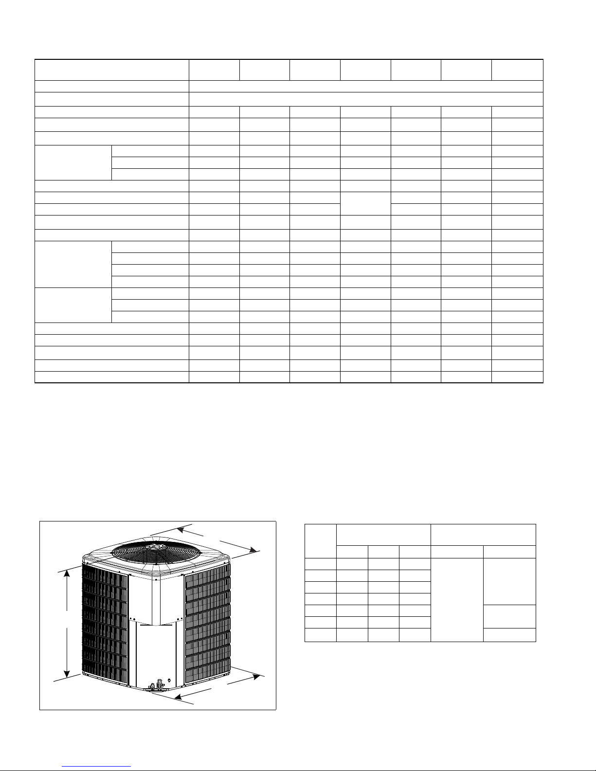
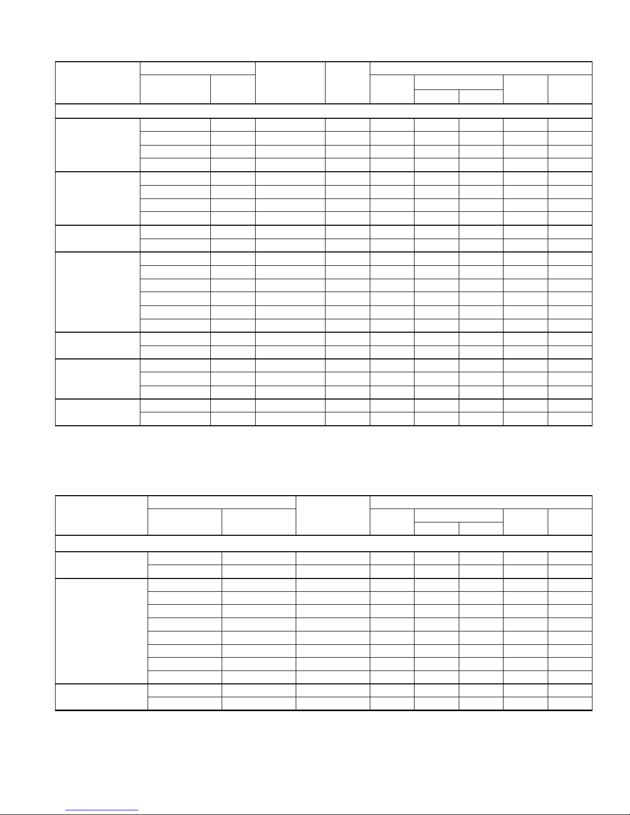
Physical and Electrical Data
MODEL
RHP14J
184S21
Unit Supply Voltage 208-230V, 1 60Hz
Normal Voltage Range
Minimum Circuit Ampacity
Max. Overcurrent Device Amps
Min. Overcurrent Device Amps
Compressor
Amps
Crankcase Heater
Factory External Discharge Muffler
Factory External Check Valve
HS Kit Required with TXV
Fan Diameter Inches
Fan Motor
Coil
Liquid Line Set OD (Field Installed)
Vapor Line Set OD (Field Installed)
Unit Charge (Lbs. - Oz.)
Charge Per Foot, Oz.
1
2
3
Type
Rated Load
Locked Rotor
4
Rated HP
Rated Load Amps
Nominal RPM
Nominal CFM
Face Area Sq. Ft.
Rows Deep
Fins / Inch
5
11.9 17.6 17.3 19.7 23.7 28.5 35.3
20 30 30 30 40 50 60
15 20 20 20 25 30 40
Scroll Scroll Scroll Recip Scroll Scroll 2-Stage Scroll
9.0 13.4 12.8 14.7 17.9 21.8 35.3
48.0 58.3 64.0 74.0 112.0 117.0 118.0
No No No Yes No No No
Yes Yes Yes
No No No No No No
No No No Yes No No No
24 22 24 24 24 24 24
1/10 1/8 1/4 1/4 1/4 1/4 1/4
0.7 0.8 1.3 1.3 1.3 1.3 1.3
825 1075 850 850 850 850 850
2000 2000 3900 3800 3600 3500 3800
15.72 19.17 23.58 23.58 23.58 23.58 23.58
1 1 1 1 1 2 2
22 22 22 22 22 18 18
3/8 3/8 3/8 3/8 3/8 3/8 3/8
3/4 3/4 3/4 3/4 7/8 7/8 1-1/8
6 - 15 7 - 14 9 - 14 10 - 6 11 - 4 13 - 1 14 - 2
0.62 0.62 0.62 0.62 0.67 0.67 0.75
Operating Weight Lbs. 145 145 176 193 198 248 290
1. Rated in accordance with AHRI Standard 110-2012, utilization range “A”.
2. Dual element fuses or HACR circuit breaker. Maximum allowable overcurrent protection.
3. Dual element fuses or HACR circuit breaker. Minimum recommended overcurrent protection.
4. See Hard Start Kit Accessory Insta llation Manual for Hard Start Kit part number for each model.
5. The Unit Charge is correct for the outdoor unit, smallest matched indoor un it, and 15 fe et of ref rig erant t ubing . For tubin g leng ths other than 15 fe et, add or subtract the amount of refrigerant, using the difference in length multiplied by the per foot value.
RHP14J
244S21
RHP14J
304S21
RHP14J
364S21
187 to 252
Combined
DM/CV
RHP14J
424S21
RHP14J
484S21
Yes Yes Yes
RHP14J
604S21
2 Johnson Controls Unitary Products
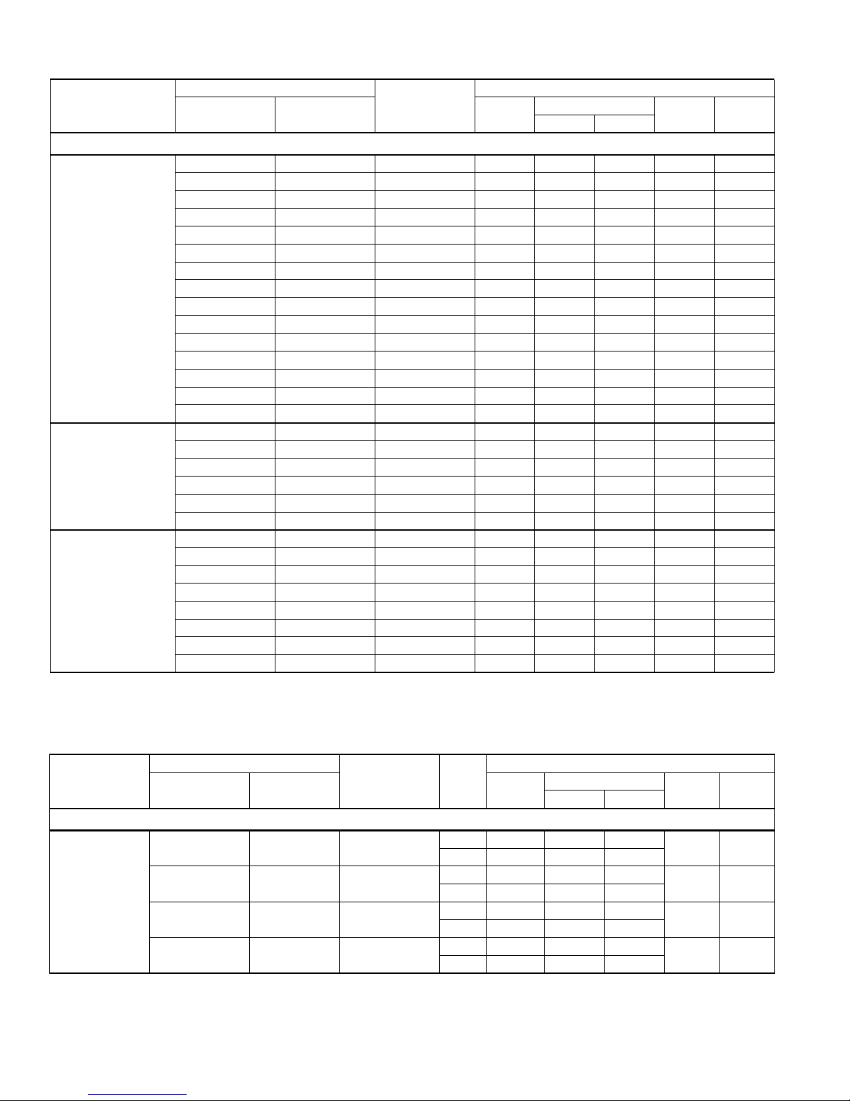
Unit
Model
Dimensions
(Inches)
A B C Liquid Vapor
Refrigerant Connection
Service Valve Size
18 28-1/4 34 34
24 40-1/4 29-1/2 29-1/2
30 40-1/4 34 34
36 40-1/4 34 34
3/8
42 40-1/4 34 34
48 40-1/4 34 34
60 40-1/4 34 34
* Adapter Fitting Required for 1-1/8" Lilneset.
All dimensions are in inches and are subject to change without notice.
Overall height is from bottom of base pan to top of fan guard.
Overall length and width include screw heads.
3/4
7/8
7/8
*
Page 3
810754-UTG-C-0214
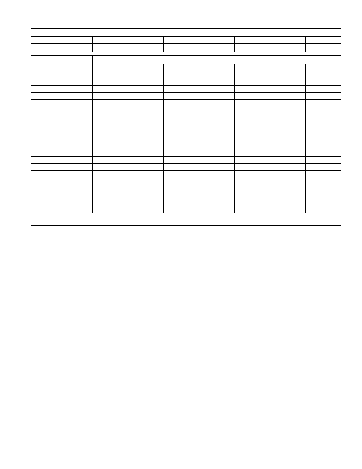
System Charge for Various Matched Systems
Outdoor Unit RHP14J184S21 RHP14J244S21 RHP14J304S21 RHP14J364S21 RHP14J424S21 RHP14J484S21 RHP14J604S21
1,2
Required Orifice or TXV
Indoor Unit
3,4,5
RFCX24BE .051 / TXV + 0 .059 / TXV + 0 – – – – –
RFCX30BE .051 / TXV + 0 .059 / TXV + 0 – – – – –
RFCX36CE – – .063 / TXV + 0 .071 / TXV + 0 – – –
RFCX42DE – – – .071 / TXV + 5 – – –
RFCX48DE – – – .071 / TXV + 25 .075 / TXV + 0 TXV + 0 –
RFCX60DE – – – – TXV + 8 TXV + 10 TXV + 0
RFCX24BP .051 / TXV + 0 .059 / TXV + 0 – – – – –
RFCX36BP – – .063 / TXV + 0 .071 / TXV + 0 – – –
RFCX42CP – – – .071 / TXV + 5 – – –
RFCX48DP – – – – .075 / TXV + 0 TXV + 0 –
RFCX60DP – – – – – – –
FC/MC/PC32 .051 / TXV + 0 .059 / TXV + 0 – – – – –
FC/MC/PC35 .051 / TXV + 0 .059 / TXV + 0 – – – – –
FC/MC/PC37 .051 / TXV + 13 .059 / TXV + 12 .063 / TXV + 0 .071 / TXV + 0 – – –
FC/MC/PC43 .051 / TXV + 13 .059 / TXV + 12 .063 / TXV + 0 .071 / TXV + 0 – – –
FC/MC/PC48 – – – .071 / TXV + 5 – – –
FC/MC/PC60 – – – .071 / TXV + 25 .075 / TXV + 0 TXV + 0 –
FC/MC62 – – – – TXV + 8 TXV + 10 TXV + 0
FC64 – – – – – TXV + 29 TXV + 8
UC48 – – – .071 / TXV + 23 – – –
UC60 – – – .071 / TXV + 38 .075 / TXV + 4 – –
Some of the combinations shown in the above System Charge table require Advanced Main Air Circulating Fan indoor product. For approved coil
only matches, please see the “COOLING CAPACITY - Upflow, Downflow & Horizontal Furnaces and Coils” table.
FOOTNOTES:
1. For applications requiring a TXV use S1-1TVM*** series kit.
2. Approved orifice(s) shipped with outdoor unit.
3. Systems matched with furnaces or air handlers not equipped with blower-off delays may require blo w er Time Delay Kit S1-2FD06700224.
4. PC coils cannot be used in downflow or horizontal applications. FC coils cannot be used in horizontal applications.
5. Refer to Cooling and Heating Performance Data tables for actual performance for specified system matches.
PROCEDURES:
1. Unit factory charge listed on the unit nameplate includ es refrigerant for the o ut door unit, the smallest matched indoor uni t, and 15 feet of interconnect ing line t ubing.
2. Verify the TXV or orifice and additional charge required for specific matched indoor unit in the system using the above table.
3. Add additional charge for the amount of interconnecting line tubing greater than 15 feet at the rate specified in Physical and Electrical Data Table.
4. For indoor matches requiring additional charge, the refrigerant needs to be weighed in for specific matched indoor unit and lineset length.
5. Permanently mark the unit nameplate with the total system charge. Total System Charge = Base Charge (as shipped) + charge adder for matched indoor unit +
charge adder for line set.
.051/4F1 .059/4G1 .063/4G1 .071/4H1 .075/4J1 4P1 4K1
Additional Charge, Oz
Johnson Controls Unitary Products 3
Page 4
810754-UTG-C-0214
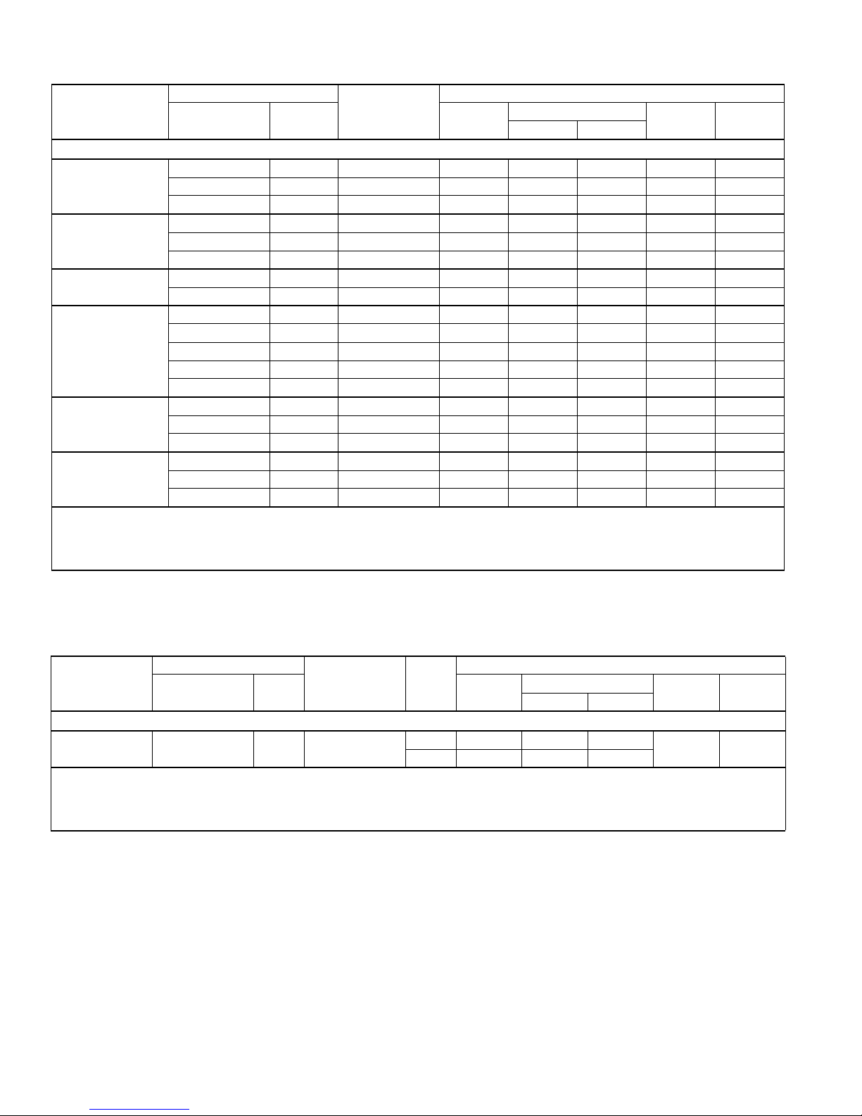
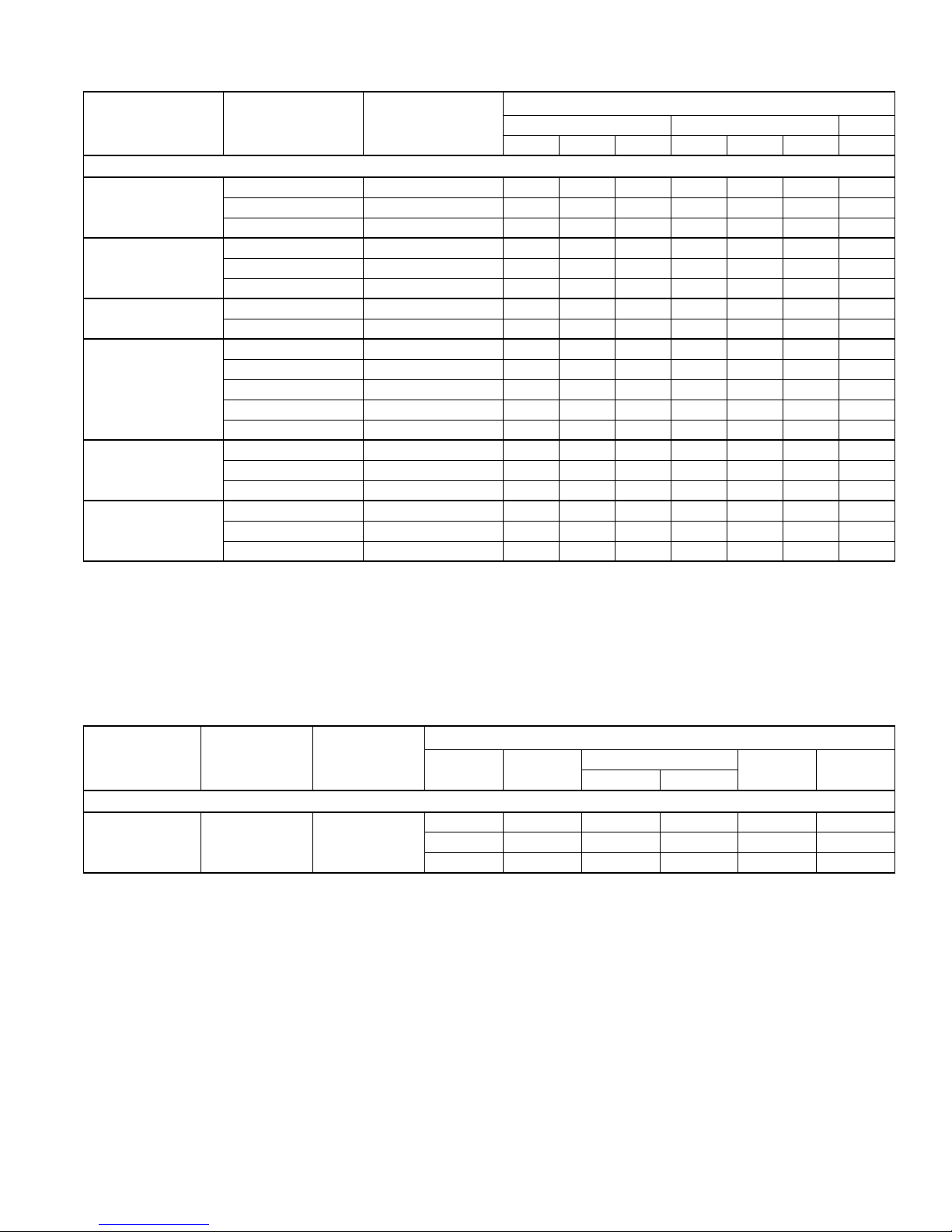
COOLING CAPACITY - With Air Handler Coils
UNIT
MODEL
AIR HANDLER
MODEL WIDTH
COIL
MODEL
1
RATED
CFM
TOTAL SENS.
14.5 SEER HP WITH AIR HANDLERS
RFCX24BE 17.5 – 585 18.0 13.3 14.50 12.00
RHP14J184S21
RFCX30BE 17.5 – 660 18.0 13.1 15.00 12.50
RFCX24BP 17.5 – 675 18.0 13.1 13.00 11.00
RFCX24BE 17.5 – 825 23.0 17.4 15.00 12.50
RHP14J244S21
RFCX30BE 17.5 – 800 23.0 17.4 15.00 12.50
RFCX24BP 17.5 – 740 22.2 16.0 13.25 11.35
RHP14J304S21
RFCX36CE 21.0 – 1000 30.0 21.7 15.00 12.50
RFCX36BP 17.5 – 1060 28.8 22.0 13.25 11.35
RFCX36CE 21.0 – 1275 36.0 27.4 14.50 12.00
RFCX42DE 24.5 – 1275 36.0 26.4 15.00 12.50
RHP14J364S21
RFCX48DE 24.5 – 1195 35.8 26.6 14.50 12.00
RFCX36BP 17.5 – 1245 35.4 26.2 13.00 11.00
RFCX42CP 21.0 – 1230 35.6 26.4 13.35 11.45
RFCX48DE 24.5 – 1125 39.5 27.0 15.00 12.50
RHP14J424S21
RFCX60DE 24.5 – 1350 39.0 28.8 14.50 12.00
RFCX48DP 24.5 – 1320 39.5 28.4 13.25 11.35
RFCX48DE 24.5 – 1295 45.5 30.8 14.00 12.00
RHP14J484S21
RFCX60DE 24.5 – 1310 47.0 31.6 15.00 12.50
RFCX48DP 24.5 – 1320 44.5 30.2 13.25 11.35
Rated in accordance with DOE test procedures (Federal Register 12-27-79 and 3-18-88) and ANSI/AHRI Standard 210/240.
Cooling MBH based on 80 °F entering air temperature, 50% RH (Relative Humidity), and rated air flow.
EER (Energy Efficiency Ratio) is the total cooling output in BTUs at 95 °F outdoor ambient divided by the total electric power in watt-hours at those conditions.
SEER (Seasonal Energy Efficiency Ratio) is the total cooling output in BTUs during a normal annual usage period for cooling divided by the total electric power
input in watt-hours during the same period.
1. MC coils available with a factory installed horizontal drain pan. See price pages for specific model number.
— = Not applicable.
MA Modular Air Handlers use Coil Only Ratings.
COOLING
NET MBH
SEER EER
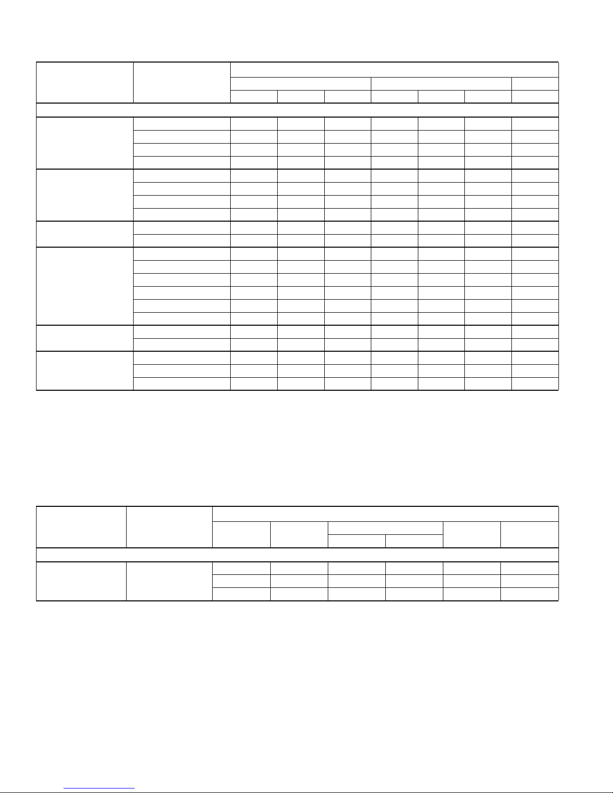
COOLING CAPACITY - With Air Handler Coils
UNIT
MODEL
AIR HANDLER
MODEL WIDTH
COIL
MODEL
STAGE
1
RATED
CFM
TOTAL SENS.
14.5 SEER HP WITH AIR HANDLERS
RHP14J604S21 RFCX60DE 24.5 –
Rated in accordance with DOE test procedures (Federal Register 12-27-79 and 3-18-88) and ANSI /AHRI Standard 210/240.
Cooling MBH based on 80 °F entering air temperature, 50% RH (Relative Humidity), and rated air flow.
EER (Energy Efficiency Ratio) is the total cooling output in BTUs at 95 °F outdoor ambient divided by the total electric power in watt-hours at those conditions.
SEER (Seasonal Energy Efficiency Ratio) is the total cooling output in BTUs during a normal annual usage period for cooling divided by the total electric power
input in watt-hours during the same period.
1. MC coils available with a factory installed horizontal drain pan. See price pages for specific model number.
— = Not applicable.
MA Modular Air Handlers use Coil Only Ratings.
1 1160 46.0 29.8
2 1835 57.0 41.0
COOLING
NET MBH
SEER EER
15.00 12.20
4 Johnson Controls Unitary Products
Page 5
COOLING CAPACITY - Upflow, Downflow & Horizontal Furnaces and Coils (Coil Only Ratings)
COIL
UNIT MODEL
MODEL WIDTH
CFM RANGE
(Min.-max.)
STAGE
RATED
CFM
TOTAL SENS.
14.5 SEER HP COIL ONLY RATINGS
FC/MC/PC32 14.5 450 - 750 – 600 18.0 12.6 13.25 11.35
RHP14J184S21
FC/MC/PC35 17.5,21.0 450 - 750 – 600 18.0 12.6 13.20 11.35
FC/MC/PC37 14.5 450 - 750 – 600 18.0 13.2 13.25 11.35
FC/MC/PC43 17.5,21.0 450 - 750 – 600 18.0 13.2 13.25 11.35
FC/MC/PC32 14.5 600 - 1000 – 800 22.2 16.3 13.25 11.35
RHP14J244S21
FC/MC/PC35 17.5,21.0 600 - 1000 – 800 22.4 16.3 13.20 11.35
FC/MC/PC37 14.5 600 - 1000 – 800 22.4 16.6 13.25 11.35
FC/MC/PC43 17.5,21.0 600 - 1000 – 800 22.4 16.6 13.25 11.35
RHP14J304S21
FC/MC/PC37 14.5 800 - 1200 – 1000 28.6 21.6 13.25 11.35
FC/MC/PC43 17.5,21.0 800 - 1200 – 1000 28.4 21.6 13.50 11.35
FC/MC/PC37 14.5 1000 - 1400 – 1200 35.0 25.6 13.00 11.00
FC/MC/PC43 17.5,21.0 1000 - 1400 – 1200 35.0 25.8 13.00 11.00
RHP14J364S21
FC/MC/PC48 21.0,24.5 1000 - 1400 – 1200 35.2 25.8 13.35 11.45
FC/MC/PC60 21.0,24.5 1000 - 1400 – 1200 35.6 26.0 13.35 11.45
UC48 21.0,24.5 1000 - 1400 – 1200 35.0 26.0 13.25 11.35
UC60 21.0,24.5 1000 - 1400 – 1200 35.0 25.6 13.25 11.35
RHP14J424S21
FC/MC/PC60 21.0,24.5 1200 - 1600 – 1200 39.0 27.0 13.25 11.35
FC/MC62 24.5 1200 - 1600 – 1400 38.0 27.8 13.00 11.00
FC/MC/PC60 21.0, 24.5 1400 - 1800 – 1400 45.5 31.6 13.25 11.35
RHP14J484S21
FC/MC62 24.5 1400 - 1800 – 1600 48.0 34.2 14.00 12.00
FC64 24.5 1400 - 1800 – 1400 48.0 32.0 14.00 12.00
RHP14J604S21
1. Requires a S1-2FD06700224 Blower Time Delay unless a standard furnace is equipped with one.
MA Modular Air Handlers use Coil Only Ratings.
Furnaces that are listed individually in the above table, such as the RGF1L*P, RGF19*P, and RGF1L*E use Coil Only Ratings.
FC/MC62 24.5 1150 - 1550 1 1350 48.0 31.8 13.30 11.35
FC/MC62 24.5 1600 - 2000 2 1800 56.5 39.5 13.30 11.35
COOLING
NET MBH
810754-UTG-C-0214
1
SEER
EER
COOLING CAPACITY - With High Efficiency Motor Furnaces
UNIT
MODEL
FURNACE
MODEL WIDTH
COIL
MODEL
1
RATED
CFM
TOTAL SENS.
14.5 SEER HP WITH HIGH EFFICIENCY MOTOR FURNACES
RHP14J184S21
RGF19*AE10 14.5 FC/MC/PC32A 600 18.0 13.5 14.50 12.50
RGF19*AE10 14.5 FC/MC/PC37A 600 18.0 13.4 13.50 11.35
RGF19*AE10 14.5 FC/MC/PC32A 775 22.2 16.5 13.25 11.35
RGF19*AE10 14.5 FC/MC/PC37A 800 22.4 16.8 13.50 11.35
RGF19*BE12 17.5 FC/MC/PC35B 800 22.4 16.7 13.70 11.35
RHP14J244S21
RGF19*BE12 17.5 FC/MC/PC43B 800 22.6 16.9 14.00 12.00
RGF19*CE16 21.0 FC/MC/PC35C 800 22.4 16.6 13.50 11.35
RGF19*CE16 21.0 FC/MC/PC43C 800 22.6 16.8 13.50 11.35
RGF19*CE20 21.0 FC/MC/PC35C 800 22.6 16.7 14.20 12.00
RGF19*CE20 21.0 FC/MC/PC43C 800 22.8 17.0 14.20 12.00
RHP14J304S21
RGF19*BE12 17.5 FC/MC/PC43B 975 29.0 21.6 15.10 12.50
RGF19*CE16 21.0 FC/MC/PC43C 1000 29.0 21.6 15.10 12.50
For notes see Page 6.
Johnson Controls Unitary Products 5
COOLING
NET MBH
2
SEER EER
Page 6
810754-UTG-C-0214
COOLING CAP ACITY - With High Efficiency Motor Furnaces (Continued)
UNIT
MODEL
MODEL WIDTH
FURNACE
14.5 SEER HP WITH HIGH EFFICIENCY MOTOR FURNACES
RGF19*BE12 17.5 FC/MC/PC43B 1125 35.8 25.4 13.25 11.35
RGF19*CE16 21.0 FC/MC/PC43C 1175 36.0 25.4 13.70 11.35
RGF19*CE16 21.0 FC/MC/PC48C 1150 36.0 25.6 14.50 12.00
RGF19*CE16 21.0 FC/PC60C 1175 35.8 25.4 14.50 12.00
RGF19*CE16 21.0 UC48C 1150 36.0 25.6 14.50 12.00
RGF19*CE16 21.0 UC60C 1175 35.6 25.4 14.20 12.00
RGF19*CE20 21.0 FC/MC/PC43C 1150 36.0 25.6 13.70 11.35
RHP14J364S21
RGF19*CE20 21.0 FC/MC/PC48C 1150 36.0 25.6 14.50 12.00
RGF19*CE20 21.0 FC/PC60C 1150 35.8 25.4 14.50 12.00
RGF19*CE20 21.0 UC48C 1150 36.0 25.6 14.50 12.00
RGF19*CE20 21.0 UC60C 1150 35.6 25.4 14.50 12.00
RGF19*DE20 24.5 FC/MC/PC48D 1175 36.0 25.8 14.50 12.00
RGF19*DE20 24.5 FC/MC/PC60D 1175 36.0 25.4 14.50 12.00
RGF19*DE20 24.5 UC48D 1175 36.0 25.8 14.50 12.00
RGF19*DE20 24.5 UC60D 1175 35.6 25.4 14.50 12.00
RGF19*CE16 21.0 FC/MC62D 1400 38.5 28.0 13.15 11.00
RGF19*CE16 21.0 FC/PC60C 1400 39.5 28.6 13.50 11.35
RHP14J424S21
RGF19*CE20 21.0 FC/MC62D 1350 39.0 28.4 13.70 11.35
RGF19*DE20 24.5 FC/MC/PC60D 1325 40.0 29.0 14.20 12.00
RGF19*DE20 24.5 FC/MC62D 1325 39.0 28.4 13.70 11.35
RGF19*DE20 24.5 UC60D 1325 37.2 27.8 13.25 11.35
RGF19*CE16 21.0 FC/MC62D 1400 47.0 32.2 14.20 12.00
RGF19*CE16 21.0 FC/PC60C 1400 45.0 30.8 13.50 11.35
RGF19*CE16 21.0 FC64D 1400 48.0 32.6 14.50 12.50
RHP14J484S21
RGF19*CE20 21.0 FC/MC62D 1350 47.5 32.4 15.00 12.50
RGF19*CE20 21.0 FC64D 1350 48.0 33.0 15.10 12.50
RGF19*DE20 24.5 FC/MC/PC60D 1325 45.5 31.2 14.20 12.00
RGF19*DE20 24.5 FC/MC62D 1325 47.5 32.4 15.00 12.50
RGF19*DE20 24.5 FC64D 1325 48.0 33.0 15.10 12.50
1. MC coils available with a factory installed horizontal drain pan. See price pages for specific model number.
2. High Efficiency Motor Furnaces have B.O.D (Blower on Delay) standard.
Furnaces that are listed individually in the above table, such as the RGF1L*P, RGF19*P, and RGF1L*E use Coil Only Ratings.
COIL
MODEL
1
RATED
CFM
TOTAL SENS.
COOLING
NET MBH
2
SEER EER
COOLING CAPACITY - With High Efficiency Motor Furnaces
UNIT
MODEL
RGF19*CE20 21.0 FC/MC62D
RGF19*CE20 21.0 FC64D
RHP14J604S21
RGF19*DE20 24.5 FC/MC62D
RGF19*DE20 24.5 FC64D
1. MC coils available with a factory installed horizontal drain pan. See price pages for specific model number.
2. High Efficiency Motor Furnaces have B.O.D (Blower on Delay) standard.
Furnaces that are listed individually in the above table, such as the RGF1L*P, RGF19*P, and RGF1L*E use Coil Only Ratings.
6 Johnson Controls Unitary Products
FURNACE
MODEL WIDTH
14.5 SEER HP WITH HIGH EFFICIENCY MOTOR FURNACES
COIL
MODEL
1
STAGE
RATED
CFM
TOTAL SENS.
1 1085 46.0 29.4
2 1550 55.5 38.0
1 1085 48.0 30.6
2 1550 57.0 39.0
1 1085 46.0 29.4
2 1550 56.0 38.0
1 1070 48.0 30.6
2 1525 57.0 39.0
NET MBH
2
COOLING
SEER EER
14.20 11.80
14.50 12.00
14.20 12.00
14.50 12.00
Page 7
810754-UTG-C-0214
HEATING CAPACITY - With Air Handler Coils
UNIT
MODEL*
AIR
HANDLER
COIL
MODEL
1
47F17F HSPF
HEATING
MBH COP KW MBH COP KW STD
14.5 SEER HP WITH AIR HANDLERS
RFCX24BE – 18.0 3.82 1.38 11.0 2.50 1.29 8.20
RHP14J184S21
RFCX30BE – 18.03.881.3610.92.541.268.50
RFCX24BP – 18.0 3.56 1.52 11.4 2.34 1.43 7.75
RFCX24BE – 22.23.681.7713.72.441.658.50
RHP14J244S21
RFCX30BE – 22.23.681.7713.72.441.658.50
RFCX24BP – 22.43.421.9213.92.301.777.75
RHP14J304S21
RFCX36CE – 30.04.082.1520.42.622.289.00
RFCX36BP – 30.03.762.4219.42.502.277.75
RFCX36CE – 34.6 3.80 2.67 20.2 2.80 2.11 8.50
RFCX42DE – 34.6 3.80 2.67 20.2 2.80 2.11 9.00
RHP14J364S21
RFCX48DE – 33.83.742.6519.82.782.098.50
RFCX36BP – 35.03.522.9120.82.582.368.20
RFCX42CP – 34.83.562.8620.82.622.338.20
RFCX48DE – 39.53.703.1325.42.662.809.00
RHP14J424S21
RFCX60DE – 39.03.783.0225.42.682.788.50
RFCX48DP – 40.53.523.3726.42.503.098.50
RFCX48DE – 47.03.444.0028.82.443.468.20
RHP14J484S21
RFCX60DE – 47.03.723.7030.42.623.409.00
RFCX48DP – 48.03.224.3729.62.263.847.80
1. Rated CFM same as for cooling.
2. Heating MBH based on AHRI standards of 70 °F DB (Dry Bulb) entering indoor air, 72% RH (Relative Humidity) outdoor air with 25 feet of interconnecting piping
and no supplemental electric heat operation.
COP equals MBH output divided by (total KW input x 3.412).
HSPF (Heating Seasonal Performance Factor) is the total heating output during a normal annual usage period for heating divided by the total electric power input
during the same period.
— = Not Applicable.
MA Modular Air Handlers use Coil Only Ratings.
2
HEATING CAPACITY - With Air Handler Coils
UNIT
MODEL
AIR
HANDLER
COIL
MODEL
1
STAGE
RATED
CFM
HEATING
NET MBH
47 OD 17 OD
14.5 SEER HP WITH AIR HANDLERS
1116043.0– –3.36
RHP14J604S21 RFCX60DE –
2 1835 58.0 40.0 9.00 3.70
2* 1160 55.0 39.5 8.85 3.00
1. Rated CFM same as for cooling.
2. Heating MBH based on AHRI standards of 70 °F DB (Dry Bulb) entering indoor air, 72% RH (Relative Humidity) outdoor air with 25 feet of interconnecting piping
and no supplemental electric heat operation.
* Notates “Hot Heat Pump” performance. These ratings are not AHRI Listed.
COP equals MBH output divided by (total KW input x 3.412).
HSPF (Heating Seasonal Performance Factor) is the total heating output during a normal annual usage period for heating divided by the total electric power input
during the same period.
— = Not Applicable.
MA Modular Air Handlers use Coil Only Ratings.
2
HSPF COP @ 47
Johnson Controls Unitary Products 7
Page 8
810754-UTG-C-0214
HEATING CAPACITY - Upflow, Downflow, and Horizontal Furnaces and Coils (Coil Only Ratings)
UNIT
MODEL*
COIL
MODEL
1
47 F 17 FHSPF
HEATING
MBH COP KW MBH COP KW STD
14.5 SEER HP COIL ONLY RATINGS
FC/MC/PC32 18.0 3.56 1.52 11.4 2.34 1.43 7.75
RHP14J184S21
FC/MC/PC35 18.0 3.52 1.56 11.3 2.34 1.45 7.70
FC/MC/PC37 18.0 3.62 1.50 11.3 2.40 1.38 7.75
FC/MC/PC43 18.0 3.62 1.50 11.3 2.40 1.38 7.75
FC/MC/PC32 22.83.401.9614.22.261.847.75
RHP14J244S21
FC/MC/PC35 22.63.381.9915.42.261.867.70
FC/MC/PC37 22.83.401.9614.22.261.847.75
FC/MC/PC43 22.83.401.9614.22.261.847.75
RHP14J304S21
FC/MC/PC37 30.03.722.4319.32.482.288.00
FC/MC/PC43 30.03.702.4319.42.582.228.00
FC/MC/PC37 35.03.522.9120.82.582.368.20
FC/MC/PC43 35.03.522.9120.82.582.368.20
RHP14J364S21
FC/MC/PC48 34.83.522.9020.82.602.348.20
FC/MC/PC60 35.43.642.8521.22.662.348.20
UC48 36.03.702.8521.42.662.367.80
UC60 36.03.682.8720.82.602.347.80
RHP14J424S21
FC/MC/PC60 40.53.523.3726.02.523.028.50
FC/MC62 40.03.543.3126.22.523.058.50
FC/MC/PC60 48.03.444.0929.62.383.647.80
RHP14J484S21
FC/MC62 48.03.763.7431.42.583.578.20
FC64 48.03.763.7431.62.603.568.20
1. Rated CFM same as for cooling.
2. Heating MBH based on AHRI standards of 70 °F DB (Dry Bulb) entering indoor air, 72% RH (Relative Humidity) outdoor air with 25 feet of interconnecting piping
and no supplemental electric heat operation.
COP equals MBH output divided by (total KW input x 3.412).
HSPF (Heating Seasonal Performance Factor) is the total heating output during a normal annual usage period for heating divided by the total electric power input
during the same period.
MA Modular Air Handlers use Coil Only Ratings.
Furnaces that are listed individually in the above table, such as the RGF1L*P, RGF19*P, and RGF1L*E use Coil Only Ratings.
— = Not Applicable.
2
HEATING CAPACITY - With Upflow, Downflow, & Horizontal Furnaces and Coils (Coil Only Ratings)
UNIT
MODEL*
RHP14J604S21 FC/MC62
1. Rated CFM same as for cooling.
2. Heating MBH based on AHRI standards of 70° DB (Dry Bulb) entering indoor air, 72% RH (Relative Humidity) outdoor air with 25 feet of interconnecting piping
and no supplemental electric heat operation.
* Notates “Hot Heat Pump” performance. These ratings are not AHRI Listed.
COP equals MBH output divided by (total KW input x 3.412).
HSPF (Heating Seasonal Performance Factor) is the total heating output during a normal annual usage period for heating divided by the total electric power input
during the same period.
MA Modular Air Handlers use Coil Only Ratings.
Furnaces that are listed individually in the above table, such as the RGF1L*P, RGF19*P, and RGF1L*E use Coil Only Ratings.
— = Not Applicable.
8 Johnson Controls Unitary Products
COIL
MODEL
1
2
HSPF COP @ 47
STAGE
RATED
CFM
HEATING
NET MBH
47 OD 17 OD
14.5 SEER HP COIL ONLY RATINGS
1 1350 43.5 – – 3.42
2 1800 60 40.5 8.4 3.58
2* 1350 57 40.0 8.6 3.36
Page 9

810754-UTG-C-0214
HEATING CAPACITY - With High Efficiency Motor Furnaces
HEATING
MODEL
FURNACE
MODEL
COIL
MODEL
1
47F17F HSPF
MBH COP KW MBH COP KW STD
14.5 SEER HP WITH HIGH EFFICIENCY MOTOR FURNACES
RHP14J184S21
RGF19*AE10 FC/MC/PC32A 18.0 3.78 1.40 11.0 2.50 1.29 8.50
RGF19*AE10 FC/MC/PC37A 18.0 3.66 1.47 11.2 2.44 1.34 7.75
RGF19*AE10 FC/MC/PC32A 22.6 3.46 1.91 14.0 2.30 1.78 7.75
RGF19*AE10 FC/MC/PC37A 22.6 3.54 1.87 14.0 2.36 1.74 7.75
RGF19*BE12 FC/MC/PC35B 22.4 3.52 1.86 13.9 2.34 1.74 7.75
RHP14J244S21
RGF19*BE12 FC/MC/PC43B 22.4 3.60 1.82 13.8 2.40 1.68 8.20
RGF19*CE16 FC/MC/PC35C 22.6 3.46 1.91 14.0 2.32 1.77 7.75
RGF19*CE16 FC/MC/PC43C 22.6 3.54 1.87 14.0 2.36 1.74 7.75
RGF19*CE20 FC/MC/PC35C 22.4 3.58 1.83 13.8 2.38 1.70 8.05
RGF19*CE20 FC/MC/PC43C 22.4 3.66 1.79 13.8 2.42 1.67 8.05
RHP14J304S21
RGF19*BE12 FC/MC/PC43B 30.0 3.92 2.26 34.6 5.16 1.96 9.00
RGF19*CE16 FC/MC/PC43C 30.0 3.90 2.27 34.8 5.16 1.98 9.00
RGF19*BE12 FC/MC/PC43B 34.6 3.66 2.77 19.4 2.56 2.22 7.75
RGF19*CE16 FC/MC/PC43C 34.4 3.72 2.71 19.2 2.62 2.15 7.75
RGF19*CE16 FC/MC/PC48C 34.4 3.66 2.75 20.4 2.72 2.20 8.20
RGF19*CE16 FC/PC60C 34.2 3.66 2.74 20.2 2.70 2.19 8.20
RGF19*CE16 UC48C 34.6 3.70 2.74 20.6 2.74 2.20 8.20
RGF19*CE16 UC60C 34.0 3.62 2.75 18.8 2.52 2.19 8.50
RGF19*CE20 FC/MC/PC43C 34.4 3.74 2.69 19.2 2.62 2.15 7.75
RHP14J364S21
RGF19*CE20 FC/MC/PC48C 34.4 3.68 2.74 20.4 2.72 2.20 8.20
RGF19*CE20 FC/PC60C 34.2 3.66 2.74 20.2 2.72 2.18 8.20
RGF19*CE20 UC48C 34.6 3.72 2.73 20.6 2.74 2.20 8.20
RGF19*CE20 UC60C 34.0 3.62 2.75 18.8 2.52 2.19 8.20
RGF19*DE20 FC/MC/PC48D 34.2 3.70 2.71 20.2 2.74 2.16 8.20
RGF19*DE20 FC/MC/PC60D 34.2 3.68 2.72 20.2 2.72 2.18 8.20
RGF19*DE20 UC48D 34.4 3.74 2.69 20.4 2.78 2.15 8.20
RGF19*DE20 UC60D 34.0 3.64 2.74 18.8 2.54 2.17 8.20
RGF19*CE16 FC/MC62D 40.0 3.58 3.27 26.2 2.54 3.02 7.70
RGF19*CE16 FC/PC60C 40.5 3.52 3.37 26.4 2.46 3.14 7.75
RHP14J424S21
RGF19*CE20 FC/MC62D 39.5 3.70 3.13 25.8 2.60 2.91 7.75
RGF19*DE20 FC/MC/PC60D 40.0 3.64 3.22 25.8 2.54 2.98 8.50
RGF19*DE20 FC/MC62D 39.5 3.70 3.13 25.8 2.62 2.89 7.75
RGF19*DE20 UC60D 39.0 3.48 3.28 25.4 2.44 3.05 7.75
RGF19*CE16 FC/MC62D 48.0 3.66 3.88 31.4 2.54 3.62 8.50
RGF19*CE16 FC/PC60C 48.0 3.24 4.39 29.8 2.26 3.86 7.75
RGF19*CE16 FC64D 48.0 3.72 3.94 31.4 2.58 3.57 8.50
RHP14J484S21
RGF19*CE20 FC/MC62D 48.0 3.74 3.76 31.0 2.60 3.49 8.50
RGF19*CE20 FC64D 48.0 3.82 3.80 31.0 2.66 3.41 9.00
RGF19*DE20 FC/MC/PC60D 48.0 3.34 4.21 29.4 2.32 3.71 8.05
RGF19*DE20 FC/MC62D 48.0 3.76 3.74 31.0 2.60 3.49 9.00
RGF19*DE20 FC64D 48.03.843.7831.02.663.419.00
1. MC coils available with a factory installed horizontal drain pan. See price pages for specific model number.
2. Heating MBH based on AHRI standards of 70 °F DB (Dry Bulb) entering indoor air, 72% RH (Relative Humidity) outdoor air with 25 feet of interconnecting piping
and no supplemental electric heat operation.
3. High Efficiency Motor Furnaces have B.O.D (Blower on Delay) standard.
COP equals MBH output divided by (total KW input x 3.412).
HSPF (Heating Seasonal Performance Factor) is the total heating output during a normal annual usage period for heating divided by the total electric power input
during the same period.
Furnaces that are listed individually in the above table, such as the RGF1L*P, RGF19*P, and RGF1L*E use Coil Only Ratings.
— = Not Applicable.
2
3
Johnson Controls Unitary Products 9
Page 10

810754-UTG-C-0214
HEATING CAPACITY - With High Efficiency Motor Furnaces
UNIT
MODEL
RHP14J604S21
1. MC coils available with a factory installed horizontal drain pan. See price pages for specific model number.
2. Heating MBH based on AHRI standards of 70 °F DB (Dry Bulb) entering indoor air, 72% RH (Relative Humidity) outdoor air with 25 feet of interconnecting piping
and no supplemental electric heat operation.
3. High Efficiency Motor Furnaces have B.O.D (Blower on Delay) standard.
* Notates “Hot Heat Pump” performance. These ratings are not AHRI Listed.
COP equals MBH output divided by (total KW input x 3.412).
HSPF (Heating Seasonal Performance Factor) is the total heating output during a normal annual usage period for heating divided by the total electric power input
during the same period.
Furnaces that are listed individually in the above table, such as the RGF1L*P, RGF19*P, and RGF1L*E use Coil Only Ratings.
— = Not Applicable.
FURNACE
MODEL
14.5 SEER HP WITH HIGH EFFICIENCY MOTOR FURNACES
RGF19*CE20 FC/MC62D
RGF19*CE20 FC64D
RGF19*DE20 FC/MC62D
RGF19*DE20 FC64D
COIL
MODEL
1
STAGE
1 1085 43.0 – – 3.20
2 1550 58.0 40.0 8.50 3.50
2* 1085 57.5 38.5 8.45 3.22
1 1085 43.5 – – 3.30
2 1550 58.0 40.0 8.20 3.60
2* 1085 57.5 39.0 8.15 3.32
1 1085 43.0 – – 3.20
2 1550 58.0 40.0 8.50 3.50
2* 1085 57.5 38.5 8.45 3.22
1 1070 43.5 – – 3.32
2 1525 58.0 40.0 8.20 3.60
2* 1070 57.5 38.5 8.15 3.32
RATED
CFM
HEATING
NET MBH
47 OD 17 OD
3
2
HSPF COP @ 47
ACCESSORIES
Refer to Price Manual for specific model numbers.
Start Assist Kit - Provides increased starting torque for areas
with low voltage. See Hard Start Kit Accessory Installation
Manual for Hard Start Kit part number for each model.
Blower Time Delay - Available to increase efficiency when
installed. Installs on indoor section and maintains blower for
approximately one minute after cooling thermostat has been
satisfied.
Low Temperature Cutout (S1-2LT06700224) - Prevents heat
pump operation below -10°F ambient temperature.
TXV Kits - S1-1TVM series thermal expansion valves precisely
meter refrigerant for optimum performance over a wide range of
conditions. See System Charge table for TXV part number for
each model.
Outdoor Thermostat (S1-2TD06700124) - Provides additional
staging of supplement al electric heat.
Thermostats - Compatible thermostat controls are available
through accessory sourcing. For optimum performance and
installation, refer to the UPGNET “Low Voltage Wiring Diagram”
document to select and apply controls.
SOUND LEVEL - TYPICAL OCTAVE BAND SPECTRUM (without tone adjustment)
Size Test Condition 63 125 250 500 1000 2000 4000 8000 dBA SQI
18
24
30
36
42
48
60
Rated in accordance with ARI Standard 270.
Cooling Mode 67 71 67 69 65 59 58 55 70 19.2
Heating Mode 68 70 66 68 67 61 60 57 71 19.2
Cooling Mode 69 73 64 67 68 64 61 57 71 19.0
Heating Mode 71 72 65 70 65 64 62 58 73 19.0
Cooling Mode 72 70 68 67 67 63 59 55 71 19.0
Heating Mode 74 72 73 68 70 64 61 57 74 19.0
Cooling Mode 73 70 72 70 68 63 60 57 73 19.1
Heating Mode 75 73 71 70 70 65 63 61 74 19.1
Cooling Mode 71 69 65 68 69 66 63 57 73 19.1
Heating Mode 70 69 68 69 69 65 62 60 73 19.0
Cooling Mode 70 73 69 70 70 64 59 57 73 19.1
Heating Mode 70 73 70 71 72 64 62 60 75 19.0
Cooling Mode - High Stage 73 70 69 72 75 65 62 59 77 19.1
Heating Mode - High Stage 74 75 72 73 76 68 66 63 79 19.0
10 Johnson Controls Unitary Products
Page 11
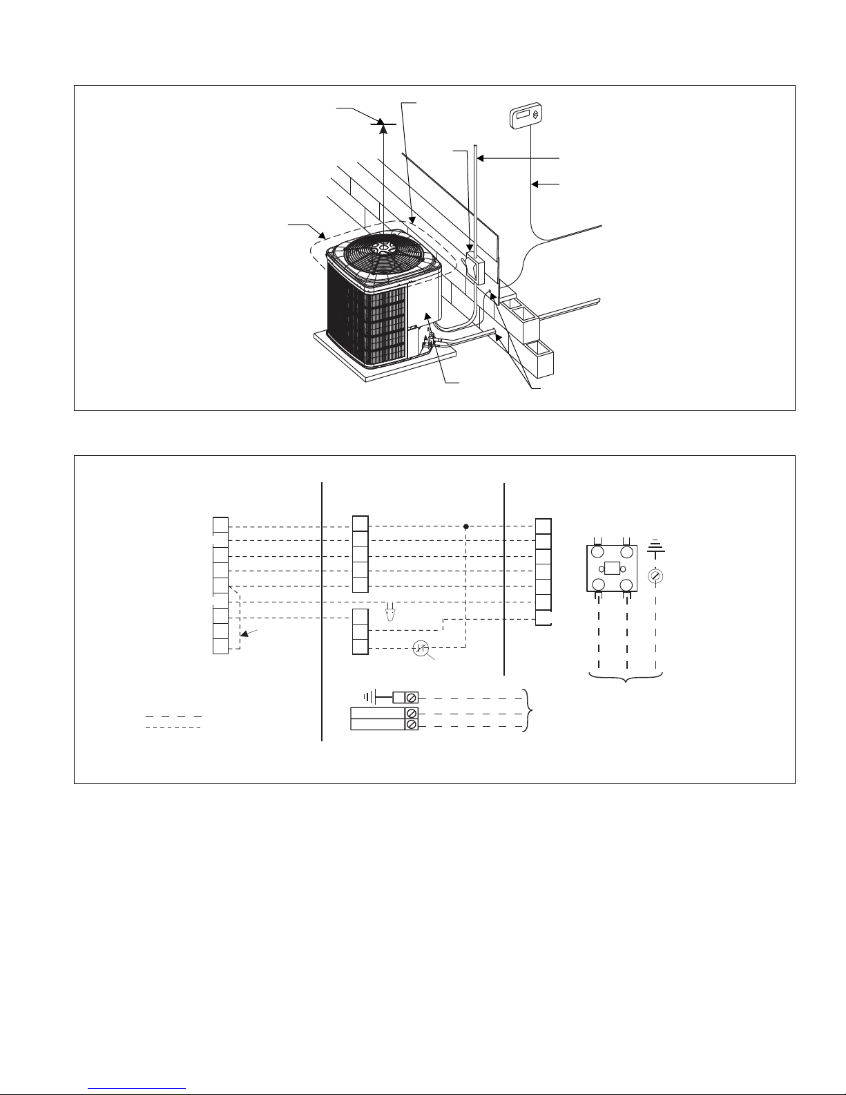
TYPICAL INSTALLATION
60” OVERHEAD
CLEARANCE
MINIMUM 18” SERVICE
ACCESS CLEARANCE
ON ONE SIDE
WEATHERPROOF
DISCONNECT
SWITCH
THERMOSTAT
10” CLEARANCE
AROUND PERIMETER
CONTROL
ACCESS
PANEL
TO INDOOR COIL
NEC CLASS 1 WIRING
NEC CLASS 2 WIRING
TO FURNACE OR
AIR HANDLER
TERMINAL BLOCK
SEAL OPENING(S) WITH
PERMAGUM OR EQUIVALENT
NOTES:
ALL OUTDOOR WIRING MUST BE WEATHERPROOF.
MINIMUM 24” UNIT TO UNIT CLEARANCE.
THERMOSTAT
INDOOR UNIT
OUTDOOR UNIT
LOW VOLTAGE TERMINAL BLOCK
IN AIR HANDLER WITH ELECTRIC HEAT
DEFROST
CONTROL
FIELD
INSTALLED
JUMPER
DEHUMIDIFICATION CONTROL CONNECTION
(Humidistat* Jumper must be removed)
GND.
SCREW
CONTACTOR
T2
T1
L2
L1
M
R
L or X
Y
O
W
G
T
2
E
2
R
R
Y
Y
O
O
W2
W
C
C
X/L
G
W1
BK
GND.
LUG
CIRCUIT
BREAKER***
POWER WIRING
24V CONTROL WIRING
(NEC CLASS 2)
JUMPER TERMINALS E AND W TO HEAT
ON FIRST STAGE DURING EMERGENCY HEAT.
TERMINAL NOT USED ON ALLTHERMOSTATS.
POWER WIRING
208/230-1-60
230-1-50
CHECK THE LOW VOLTAGE TERMINAL BLOCK ON THE INDOOR UNIT FOR THE ACTUAL ARRANGEMENT OF THE TERMINALS.
CONNECT POWER WIRING TO TERMINAL BLOCK 3TB ON UNITS WITHOUT ELECTRIC HEAT OR CIRCUIT BREAKER.
B or C
ALL FIELD WIRING TO BE IN ACCORDANCE WITH ELECTRIC CODE (NEC) AND/OR LOCAL CODES
RED
BLK
YEL
ORG
WHT
PUR
BRN
1
2
3
4
1
3,4
W1/66
810754-UTG-C-0214
TYPICAL FIELD WIRING
Johnson Controls Unitary Products 11
Page 12

810754-UTG-C-0214
COOLING PERFORMANCE DATA
CONDENSING UNIT MODEL NO. RHP14J184S21
CONDENSING
ENTERING AIR
TEMPERATURE
65
75
85
95
105
115
125
NOTE: ALL CAPACITIES INCLUDE INDOOR FAN HEAT. KW VALUES ARE FOR THE SYSTEM (OUTDOOR + INDOOR).
Multipliers for determining the performance with other indoor sections.
NOTE: For dry bulb temperatures different than those listed (between 73-87 °F), sensible capacity increases by 1060 BTUH per 1000 CFM per degree above the listed
temperature and decreases by 1060 BTUH per 1000 CFM per degree below the listed temperature.
IDCFM 400 600 800
ID DB (°F) 80 80 75 80 80 80 80 75 80 80 80 80 75 80 80
ID WB (°F) 57 62 62 67 72 57 62 62 67 72 57 62 62 67 72
T.C.
S.C.
KW
T.C.
S.C.
KW
T.C.
S.C.
KW
T.C.
S.C.
KW
T.C.
S.C.
KW
T.C.
S.C.
KW
T.C.
S.C.
KW
17.2 18.8 18.8 20.5 22.2 19.2 19.9 20.1 21.7 22.9 21.2 20.9 21.3 22.8 23.6
16.8 14.9 12.9 12.9 11.0 18.8 17.7 15.2 14.7 11.7 20.8 20.5 17.4 16.5 12.5
0.86 0.89 0.89 0.88 0.88 0.94 0.96 0.96 0.95 0.95 1.02 1.02 1.02 1.02 1.02
16.4 17.9 17.9 19.7 21.3 18.4 19.1 19.0 20.8 22.1 20.4 20.2 20.2 21.8 22.9
16.1 14.5 12.5 12.5 10.5 18.0 17.1 14.8 14.4 11.5 20.0 19.8 17.0 16.3 12.4
0.99 1.02 1.02 1.02 1.02 1.08 1.09 1.09 1.09 1.10 1.17 1.16 1.17 1.17 1.18
15.7 17.0 17.0 18.9 20.4 17.7 18.3 18.0 19.9 21.3 19.6 19.5 19.1 20.8 22.1
15.4 14.1 12.1 12.1 10.1 17.3 16.6 14.3 14.2 11.2 19.2 19.1 16.6 16.2 12.2
1.12 1.14 1.14 1.15 1.17 1.22 1.23 1.22 1.24 1.25 1.31 1.31 1.31 1.32 1.33
15.0 16.1 16.1 18.1 19.6 16.9 17.4 17.0 19.0 20.4 18.8 18.8 18.0 19.8 21.3
14.7 13.7 11.6 11.8 9.7 16.5 16.0 13.9 13.9 10.9 18.4 18.4 16.2 16.0 12.1
1.25 1.26 1.26 1.29 1.31 1.36 1.36 1.36 1.38 1.40 1.46 1.46 1.45 1.46 1.49
14.0 14.7 14.8 16.7 18.4 15.9 16.2 15.7 17.6 19.2 17.7 17.7 16.6 18.5 20.1
13.7 13.1 11.0 11.2 9.2 15.5 15.2 13.3 13.4 10.4 17.3 17.3 15.6 15.6 11.6
1.41 1.42 1.42 1.45 1.48 1.52 1.52 1.51 1.54 1.57 1.63 1.63 1.61 1.63 1.65
13.1 13.4 13.4 15.4 17.2 14.8 15.0 14.4 16.2 18.0 16.6 16.6 15.3 17.1 18.8
12.8 12.5 10.5 10.6 8.7 14.5 14.4 12.7 12.9 9.9 16.2 16.2 15.0 15.1 11.2
1.56 1.57 1.57 1.60 1.65 1.68 1.68 1.67 1.70 1.74 1.80 1.80 1.77 1.80 1.82
12.2 12.1 12.1 14.0 16.1 13.8 13.8 13.0 14.9 16.8 15.5 15.5 14.0 15.7 17.5
11.9 11.9 9.9 10.1 8.2 13.5 13.5 12.1 12.3 9.5 15.1 15.1 14.0 14.6 10.7
1.72 1.72 1.72 1.76 1.82 1.84 1.84 1.82 1.87 1.90 1.97 1.97 1.92 1.97 1.99
Air Handler Coil T.C. S.C. KW
– FC/MC/PC32 0.96 0.94 1.11
– FC/MC/PC35 0.96 0.94 1.11
– FC/MC/PC37 0.96 0.95 1.11
– FC/MC/PC43 0.96 0.95 1.11
RFCX24BE – 0.98 0.96 1.00
RFCX30BE – 0.98 0.96 1.01
RFCX24BP – 0.96 0.94 1.11
Furnace Coil T.C. S.C. KW
RGF19*AE10 FC/MC/PC32A 0.98 0.97 1.03
RGF19*AE10 FC/MC/PC37A 0.99 0.98 1.03
12 Johnson Controls Unitary Products
Page 13

810754-UTG-C-0214
COOLING PERFORMANCE DATA
CONDENSING UNIT MODEL NO. RHP14J244S21
CONDENSING
ENTERING AIR
TEMPERATURE
65
75
85
95
105
115
125
NOTE: ALL CAPACITIES INCLUDE INDOOR FAN HEAT. KW VALUES ARE FOR THE SYSTEM (OUTDOOR + INDOOR).
Multipliers for determining the performance with other indoor sections.
NOTE: For dry bulb temperatures different than those listed (between 73-87 °F), sensible capacity increases by 1060 BTUH per 1000 CFM per degree above the listed
temperature and decreases by 1060 BTUH per 1000 CFM per degree below the listed temperature.
IDCFM 600 800 1000
ID DB (°F) 80 80 75 80 80 80 80 75 80 80 80 80 75 80 80
ID WB (°F) 57 62 62 67 72 57 62 62 67 72 57 62 62 67 72
T.C. 21.7 23.6 23.5 25.2 26.6 23.4 24.1 24.3 26.0 27.2 25.1 24.6 25.1 26.9 27.8
S.C. 21.4 19.4 16.6 16.2 13.7 23.1 21.8 18.5 17.9 14.3 24.8 24.3 20.5 19.5 15.0
KW 1.20 1.22 1.22 1.23 1.21 1.28 1.29 1.31 1.29 1.28 1.36 1.35 1.39 1.35 1.35
T.C. 20.8 22.3 22.2 24.0 25.7 22.4 23.0 23.0 24.8 26.3 24.1 23.8 23.8 25.7 26.9
S.C. 20.5 18.8 16.0 15.7 13.1 22.1 21.1 18.0 17.5 13.9 23.8 23.5 19.9 19.2 14.6
KW 1.36 1.37 1.37 1.38 1.39 1.45 1.45 1.45 1.46 1.47 1.53 1.53 1.53 1.53 1.54
T.C. 19.8 20.9 20.9 22.9 24.8 21.4 21.9 21.6 23.7 25.5 23.1 22.9 22.4 24.5 26.1
S.C. 19.5 18.2 15.4 15.3 12.5 21.2 20.4 17.4 17.1 13.4 22.8 22.6 19.4 18.9 14.3
KW 1.52 1.53 1.53 1.54 1.57 1.61 1.61 1.59 1.62 1.65 1.70 1.70 1.66 1.71 1.73
T.C. 18.8 19.5 19.6 21.8 23.9 20.5 20.8 20.3 22.5 24.6 22.1 22.1 21.1 23.2 25.3
S.C. 18.6 17.5 14.8 14.8 11.9 20.2 19.7 16.8 16.7 12.9 21.8 21.8 18.8 18.7 14.0
KW 1.67 1.68 1.68 1.69 1.75 1.77 1.78 1.74 1.79 1.83 1.87 1.87 1.79 1.89 1.92
T.C. 17.7 18.0 18.0 20.2 22.4 19.2 19.3 18.7 20.9 23.1 20.7 20.7 19.4 21.6 23.7
S.C. 17.4 16.8 14.1 14.2 11.3 18.9 18.7 16.1 16.1 12.4 20.5 20.5 18.2 18.1 13.5
KW 1.86 1.87 1.87 1.90 1.96 1.97 1.97 1.94 2.00 2.04 2.07 2.07 2.02 2.09 2.12
T.C. 16.5 16.4 16.4 18.7 20.9 17.9 17.9 17.0 19.3 21.6 19.4 19.4 17.7 20.0 22.2
S.C. 16.3 16.1 13.4 13.5 10.8 17.7 17.6 15.4 15.5 11.9 19.2 19.2 17.5 17.5 13.0
KW 2.05 2.05 2.05 2.11 2.16 2.16 2.16 2.15 2.21 2.24 2.26 2.26 2.24 2.30 2.32
T.C. 15.3 14.8 14.8 17.1 19.4 16.7 16.4 15.4 17.7 20.0 18.1 18.1 16.1 18.3 20.6
S.C. 15.1 14.8 12.7 12.9 10.2 16.5 16.4 14.7 14.9 11.3 17.8 17.8 16.1 16.9 12.5
KW 2.25 2.24 2.24 2.33 2.37 2.35 2.35 2.35 2.42 2.45 2.46 2.46 2.46 2.51 2.52
Air Handler Coil T.C. S.C. KW
– FC/MC/PC32 0.99 0.98 1.09
– FC/MC/PC35 0.99 0.98 1.09
– FC/MC/PC37 1.00 0.99 1.09
– FC/MC/PC43 1.00 0.99 1.09
RFCX24BE – 1.00 1.01 1.00
RFCX30BE – 1.00 1.01 1.00
RFCX24BP – 0.99 0.96 1.04
Furnace Coil T.C. S.C. KW
RGF19*AE10 FC/MC/PC32A 0.99 0.94 1.00
RGF19*AE10 FC/MC/PC37A 0.99 0.94 1.00
RGF19*BE12 FC/MC/PC35B 1.01 1.01 0.97
RGF19*BE12 FC/MC/PC43B 1.03 1.06 0.97
RGF19*CE16 FC/MC/PC35C 1.01 0.99 0.97
RGF19*CE16 FC/MC/PC43C 1.02 1.02 0.97
RGF19*CE20 FC/MC/PC35C 1.02 1.03 0.99
RGF19*CE20 FC/MC/PC43C 1.02 1.02 0.98
Johnson Controls Unitary Products 13
Page 14
810754-UTG-C-0214
COOLING PERFORMANCE DATA
CONDENSING UNIT MODEL NO. RHP14J304S21
CONDENSING
ENTERING AIR
TEMPERATURE
65
75
85
95
105
115
125
NOTE: ALL CAPACITIES INCLUDE INDOOR FAN HEAT. KW VALUES ARE FOR THE SYSTEM (OUTDOOR + INDOOR).
Multipliers for determining the performance with other indoor sections.
NOTE: For dry bulb temperatures different than those listed (between 73-87 °F), sensible capacity increases by 1060 BTUH per 1000 CFM per degree above the listed
temperature and decreases by 1060 BTUH per 1000 CFM per degree below the listed temperature.
Air Handler Coil T.C. S.C. KW
– FC/MC/PC37 0.98 0.96 1.10
– FC/MC/PC43 0.98 0.96 1.10
RFCX36CE – 1.00 0.98 1.00
RFCX36BP – 0.98 0.98 1.11
IDCFM 800 1000 1200
ID DB (°F) 80 80 75 80 80 80 80 75 80 80 80 80 75 80 80
ID WB (°F) 57 62 62 67 72 57 62 62 67 72 57 62 62 67 72
T.C. 28.4 30.2 30.1 33.0 34.3 30.2 31.2 31.2 33.5 34.8 32.0 32.2 32.2 34.0 35.3
S.C. 28.4 26.3 22.5 22.3 18.2 30.2 29.6 24.6 23.7 18.7 32.0 32.2 26.8 25.1 19.1
KW 1.49 1.53 1.53 1.55 1.52 1.60 1.63 1.63 1.60 1.59 1.70 1.74 1.74 1.65 1.66
T.C. 27.3 28.7 28.7 31.5 33.2 29.0 29.7 29.6 32.1 33.7 30.7 30.6 30.6 32.7 34.2
S.C. 27.3 25.7 21.8 21.6 17.7 29.0 28.4 23.9 23.2 18.2 30.7 30.6 26.1 24.8 18.7
KW 1.67 1.69 1.69 1.72 1.70 1.76 1.78 1.78 1.78 1.77 1.86 1.86 1.86 1.84 1.85
T.C. 26.2 27.2 27.2 30.0 32.2 27.8 28.1 28.1 30.7 32.6 29.5 29.0 29.0 31.4 33.1
S.C. 26.2 25.0 21.1 21.0 17.1 27.8 27.3 23.3 22.8 17.7 29.5 29.0 25.4 24.6 18.4
KW 1.84 1.86 1.86 1.88 1.88 1.93 1.92 1.92 1.95 1.96 2.03 1.99 1.99 2.02 2.03
T.C. 25.1 25.8 25.8 28.6 31.1 26.7 26.6 26.6 29.3 31.5 28.2 27.3 27.3 30.1 32.0
S.C. 25.1 24.4 20.4 20.4 16.5 26.7 26.1 22.6 22.4 17.3 28.2 27.3 24.7 24.4 18.1
KW 2.01 2.02 2.02 2.05 2.06 2.10 2.07 2.06 2.13 2.14 2.19 2.11 2.11 2.20 2.21
T.C. 23.7 23.8 23.9 26.9 29.5 25.2 25.1 24.6 27.6 29.9 26.7 26.3 25.4 28.2 30.3
S.C. 23.7 23.4 19.6 19.7 15.7 25.2 25.1 21.7 21.7 16.6 26.7 26.3 23.9 23.7 17.5
KW 2.22 2.23 2.23 2.27 2.30 2.31 2.29 2.29 2.35 2.37 2.40 2.36 2.36 2.43 2.44
T.C. 22.2 21.9 21.9 25.2 27.8 23.7 23.6 22.7 25.8 28.3 25.2 25.2 23.4 26.4 28.7
S.C. 22.2 21.9 18.7 19.0 15.0 23.7 23.6 20.9 21.0 16.0 25.2 25.2 23.1 23.0 17.0
KW 2.44 2.43 2.43 2.50 2.53 2.52 2.52 2.52 2.57 2.60 2.61 2.61 2.61 2.65 2.67
T.C. 20.8 19.9 20.0 23.5 26.2 22.2 22.1 20.7 24.0 26.7 23.7 24.2 21.5 24.5 27.1
S.C. 20.8 19.9 17.8 18.3 14.2 22.2 22.1 20.1 20.3 15.3 23.7 24.2 21.5 22.3 16.4
KW 2.65 2.64 2.64 2.72 2.76 2.74 2.75 2.75 2.80 2.83 2.82 2.86 2.85 2.88 2.90
Furnace Coil T.C. S.C. KW
RGF19*BE12 FC/MC/PC43B 0.99 0.98 1.02
RGF19*CE16 FC/MC/PC43C 0.99 0.96 1.02
14 Johnson Controls Unitary Products
Page 15

810754-UTG-C-0214
COOLING PERFORMANCE DATA
CONDENSING UNIT MODEL NO. RHP14J364S21
CONDENSING
ENTERING AIR
TEMPERATURE
65
75
85
95
105
115
125
NOTE: ALL CAPACITIES INCLUDE INDOOR FAN HEAT. KW VALUES ARE FOR THE SYSTEM (OUTDOOR + INDOOR).
Multipliers for determining the performance with other indoor sections.
NOTE: For dry bulb temperatures different than those listed (between 73-87 °F), sensible capacity increases by 1060 BTUH per 1000 CFM per degree above the listed
temperature and decreases by 1060 BTUH per 1000 CFM per degree below the listed temperature.
IDCFM 1000 1200 1400
ID DB (°F) 80 80 75 80 80 80 80 75 80 80 80 80 75 80 80
ID WB (°F) 57 62 62 67 72 57 62 62 67 72 57 62 62 67 72
T.C.
S.C.
KW
T.C.
S.C.
KW
T.C.
S.C.
KW
T.C.
S.C.
KW
T.C.
S.C.
KW
T.C.
S.C.
KW
T.C.
S.C.
KW
37.2 39.5 39.5 43.2 45.5 39.3 41.1 41.0 44.1 46.4 41.4 42.7 42.5 45.1 47.3
36.9 32.5 27.9 27.8 23.2 39.0 36.0 30.2 29.8 24.2 41.0 39.6 32.5 31.8 25.3
2.11 2.18 2.18 2.19 2.19 2.22 2.27 2.26 2.27 2.30 2.32 2.36 2.34 2.35 2.40
34.9 36.8 36.8 40.6 43.4 37.0 38.1 38.2 41.5 44.2 39.0 39.5 39.5 42.5 44.9
34.7 31.3 26.7 26.6 22.0 36.7 34.3 28.9 28.7 23.1 38.7 37.3 31.2 30.7 24.2
2.29 2.34 2.34 2.38 2.41 2.40 2.43 2.43 2.46 2.49 2.51 2.52 2.52 2.55 2.58
32.7 34.0 34.1 38.0 41.3 34.7 35.2 35.3 39.0 41.9 36.7 36.3 36.4 39.9 42.4
32.4 30.0 25.5 25.5 20.8 34.4 32.5 27.7 27.5 21.9 36.4 35.0 29.9 29.5 23.0
2.47 2.50 2.50 2.56 2.62 2.58 2.59 2.60 2.66 2.69 2.70 2.67 2.69 2.75 2.75
30.5 31.3 31.4 35.4 39.2 32.4 32.2 32.4 36.4 39.6 34.3 33.0 33.4 37.4 40.0
30.2 28.8 24.3 24.3 19.6 32.2 30.8 26.4 26.4 20.7 34.1 32.8 28.5 28.4 21.9
2.65 2.67 2.67 2.74 2.83 2.77 2.75 2.77 2.85 2.88 2.89 2.83 2.87 2.95 2.93
27.5 28.4 28.2 32.2 36.2 29.6 29.7 28.9 33.1 36.8 31.7 31.0 29.5 34.0 37.4
27.3 27.1 22.9 23.0 18.4 29.4 28.9 24.9 25.1 19.6 31.5 30.8 27.0 27.1 20.8
2.80 2.81 2.80 2.92 3.01 2.92 2.90 2.91 3.02 3.09 3.03 2.99 3.02 3.13 3.16
24.6 25.5 25.0 29.0 33.2 26.9 27.3 25.4 29.8 34.0 29.1 29.0 25.7 30.6 34.9
24.4 25.3 21.5 21.7 17.3 26.6 27.1 23.5 23.8 18.5 28.9 28.8 25.4 25.8 19.7
2.96 2.95 2.93 3.10 3.20 3.07 3.05 3.04 3.20 3.29 3.18 3.15 3.16 3.30 3.39
21.7 22.6 21.8 25.8 30.1 24.1 24.8 21.9 26.5 31.2 26.5 27.0 21.9 27.2 32.3
21.5 22.6 20.1 20.4 16.1 23.9 24.8 21.9 22.5 17.4 26.3 26.8 21.9 24.5 18.7
3.11 3.09 3.06 3.28 3.38 3.22 3.20 3.18 3.38 3.50 3.33 3.31 3.31 3.48 3.61
Air Handler Coil T.C. S.C. KW
– FC/MC/PC37 0.98 0.98 1.09
– FC/MC/PC43 0.98 0.98 1.09
– FC/MC/PC48 0.99 0.99 1.10
– FC/MC/PC60 1.00 0.99 1.09
– UC48 1.00 0.99 1.09
– UC60 0.98 0.97 1.09
RFCX36CE – 1.02 1.04 1.01
RFCX42DE – 1.00 1.00 1.00
RFCX48DE – 1.00 1.00 1.00
RFCX36BP – 1.00 0.99 1.10
RFCX42CP – 1.00 1.00 1.08
Furnace Coil T.C. S.C. KW
RGF19*BE12 FC/MC/PC43B 0.99 0.99 1.07
RGF19*CE16 FC/MC/PC43C 0.99 0.97 1.03
RGF19*CE16 FC/MC/PC48C 1.00 0.99 1.04
RGF19*CE16 FC/PC60C 0.99 0.97 1.04
RGF19*CE16 UC48C 1.00 0.99 1.04
RGF19*CE16 UC60C 0.98 0.97 1.04
RGF19*CE20 FC/MC/PC43C 1.00 0.99 1.03
RGF19*CE20 FC/MC/PC48C 1.00 0.99 1.04
RGF19*CE20 FC/PC60C 0.99 0.98 1.04
RGF19*CE20 UC48C 1.00 0.99 1.04
RGF19*CE20 UC60C 0.98 0.98 1.04
RGF19*DE20 FC/MC/PC48D 1.00 0.99 1.03
RGF19*DE20 FC/MC/PC60D 0.99 0.97 1.03
RGF19*DE20 UC48D 1.00 0.99 1.03
RGF19*DE20 UC60D 0.98 0.97 1.03
Johnson Controls Unitary Products 15
Page 16

810754-UTG-C-0214
COOLING PERFORMANCE DATA
CONDENSING UNIT MODEL NO. RHP14J424S21
CONDENSING
ENTERING AIR
TEMPERATURE
65
75
85
95
105
115
125
NOTE: ALL CAPACITIES INCLUDE INDOOR FAN HEAT. KW VALUES ARE FOR THE SYSTEM (OUTDOOR + INDOOR).
Multipliers for determining the performance with other indoor sections.
NOTE: For dry bulb temperatures different than those listed (between 73-87 °F), sensible capacity increases by 1060 BTUH per 1000 CFM per degree above the listed
temperature and decreases by 1060 BTUH per 1000 CFM per degree below the listed temperature.
IDCFM 1155 1355 1555
ID DB (°F) 80 80 75 80 80 80 80 75 80 80 80 80 75 80 80
ID WB (°F) 57 62 62 67 72 57 62 62 67 72 57 62 62 67 72
T.C. 38.5 40.6 41.2 44.8 48.2 40.3 41.9 41.0 45.8 49.3 42.2 43.3 40.7 46.7 50.4
S.C. 38.5 35.5 30.5 30.2 24.7 40.3 39.2 32.0 32.1 25.8 42.2 42.9 33.6 33.9 26.8
KW 2.20 2.21 2.21 2.23 2.36 2.27 2.28 2.28 2.35 2.44 2.34 2.35 2.34 2.47 2.52
T.C. 36.9 38.6 39.0 42.8 46.3 38.7 39.7 39.1 43.7 47.3 40.6 40.8 39.2 44.6 48.3
S.C. 36.9 34.8 29.6 29.4 23.8 38.7 37.7 31.3 31.3 24.9 40.6 40.6 33.0 33.2 26.0
KW 2.48 2.49 2.49 2.53 2.62 2.57 2.57 2.57 2.64 2.71 2.65 2.65 2.64 2.74 2.80
T.C. 35.3 36.7 36.9 40.8 44.3 37.2 37.5 37.2 41.6 45.3 39.0 38.3 37.6 42.4 46.2
S.C. 35.3 34.0 28.6 28.6 23.0 37.2 36.2 30.5 30.5 24.1 39.0 38.3 32.5 32.4 25.1
KW 2.76 2.78 2.78 2.84 2.88 2.86 2.86 2.86 2.92 2.98 2.96 2.95 2.94 3.01 3.08
T.C. 33.7 34.8 34.7 38.8 42.3 35.6 35.3 35.4 39.6 43.2 37.4 35.8 36.1 40.3 44.1
S.C. 33.7 33.3 27.7 27.7 22.2 35.6 34.7 29.8 29.7 23.2 37.4 35.8 31.9 31.6 24.3
KW 3.04 3.06 3.06 3.14 3.14 3.15 3.16 3.15 3.21 3.25 3.26 3.25 3.24 3.29 3.36
T.C. 31.7 32.2 31.4 35.9 39.8 33.4 33.3 32.3 36.7 40.5 35.1 34.3 33.1 37.5 41.3
S.C. 31.7 31.6 26.3 26.6 21.1 33.4 33.1 28.5 28.6 22.2 35.1 34.3 30.7 30.6 23.3
KW 3.35 3.36 3.37 3.40 3.47 3.46 3.46 3.46 3.50 3.57 3.58 3.55 3.54 3.60 3.67
T.C. 29.7 29.7 28.2 33.0 37.2 31.2 31.2 29.2 33.8 37.8 32.7 32.7 30.2 34.7 38.5
S.C. 29.7 29.7 24.9 25.4 20.1 31.2 31.2 27.2 27.5 21.2 32.7 32.7 29.5 29.6 22.3
KW 3.66 3.67 3.69 3.66 3.80 3.78 3.75 3.76 3.79 3.89 3.89 3.84 3.83 3.92 3.98
T.C. 27.6 27.1 25.0 30.1 34.6 29.0 29.2 26.1 31.0 35.1 30.4 31.2 27.2 31.9 35.6
S.C. 27.6 27.1 23.6 24.3 19.1 29.0 29.2 25.9 26.4 20.2 30.4 31.2 27.2 28.6 21.4
KW 3.97 3.97 4.01 3.92 4.13 4.09 4.05 4.07 4.08 4.21 4.21 4.13 4.13 4.23 4.29
Air Handler Coil T.C. S.C. KW
– FC/MC62 0.97 0.93 1.07
– FC/MC/PC60 1.02 1.00 1.08
RFCX48DE – 1.03 1.00 1.01
RFCX60DE – 1.00 1.00 1.00
RFCX48DP – 1.02 0.98 1.06
Furnace Coil T.C. S.C. KW
RGF19*CE16 FC/MC62D 0.98 0.94 1.07
RGF19*CE16 FC/PC60C 1.01 0.96 1.07
RGF19*CE20 FC/MC62D 1.00 0.97 1.04
RGF19*DE20 FC/MC/PC60D 1.03 1.00 1.03
RGF19*DE20 FC/MC62D 1.00 0.98 1.04
RGF19*DE20 UC60D 0.96 0.96 1.01
16 Johnson Controls Unitary Products
Page 17

810754-UTG-C-0214
COOLING PERFORMANCE DATA
CONDENSING UNIT MODEL NO. RHP14J484S21
CONDENSING
ENTERING AIR
TEMPERATURE
65
75
85
95
105
115
125
NOTE: ALL CAPACITIES INCLUDE INDOOR FAN HEAT. KW VALUES ARE FOR THE SYSTEM (OUTDOOR + INDOOR).
Multipliers for determining the performance with other indoor sections.
NOTE: For dry bulb temperatures different than those listed (between 73-87 °F), sensible capacity increases by 1060 BTUH per 1000 CFM per degree above the listed
temperature and decreases by 1060 BTUH per 1000 CFM per degree below the listed temperature.
IDCFM 1400 1600 1800
ID DB (°F) 80 80 75 80 80 80 80 75 80 80 80 80 75 80 80
ID WB (°F) 57 62 62 67 72 57 62 62 67 72 57 62 62 67 72
T.C.
S.C.
KW
T.C.
S.C.
KW
T.C.
S.C.
KW
T.C.
S.C.
KW
T.C.
S.C.
KW
T.C.
S.C.
KW
T.C.
S.C.
KW
46.3 48.5 48.5 53.1 57.3 48.0 50.1 49.9 53.5 58.0 49.8 51.6 51.4 53.9 58.7
46.3 42.2 35.8 35.4 29.2 48.0 45.7 38.1 36.7 29.9 49.8 49.3 40.4 38.0 30.6
2.67 2.73 2.72 2.76 2.74 2.77 2.80 2.80 2.81 2.80 2.87 2.87 2.87 2.86 2.87
44.4 46.1 46.1 50.7 55.0 46.2 47.4 47.3 51.3 55.8 48.0 48.7 48.5 51.8 56.5
44.4 41.2 34.8 34.4 28.2 46.2 44.2 37.0 36.0 29.0 48.0 47.1 39.2 37.5 29.8
3.00 3.04 3.04 3.05 3.09 3.10 3.12 3.12 3.13 3.16 3.20 3.20 3.20 3.21 3.23
42.4 43.6 43.6 48.3 52.7 44.3 44.7 44.7 49.0 53.5 46.2 45.7 45.7 49.8 54.3
42.4 40.2 33.7 33.5 27.1 44.3 42.6 35.8 35.3 28.0 46.2 45.0 38.0 37.0 29.0
3.33 3.35 3.35 3.34 3.44 3.43 3.44 3.44 3.45 3.52 3.54 3.53 3.53 3.56 3.60
40.5 41.1 41.2 45.9 50.5 42.5 42.0 42.0 46.8 51.3 44.4 42.8 42.8 47.7 52.1
40.5 39.2 32.7 32.6 26.0 42.5 41.0 34.7 34.6 27.1 44.4 42.8 36.8 36.5 28.2
3.66 3.66 3.66 3.63 3.80 3.76 3.76 3.76 3.77 3.88 3.87 3.86 3.86 3.91 3.97
37.9 38.3 37.6 42.7 47.5 39.7 39.5 38.5 43.5 48.2 41.5 40.7 39.3 44.3 48.8
37.9 37.4 31.1 31.4 24.8 39.7 39.1 33.2 33.3 25.9 41.5 40.7 35.3 35.3 26.9
4.05 4.05 4.04 4.10 4.22 4.17 4.17 4.13 4.21 4.30 4.29 4.28 4.23 4.33 4.38
35.2 35.5 34.0 39.5 44.6 36.9 37.1 34.9 40.2 45.1 38.7 38.7 35.8 41.0 45.5
35.2 35.5 29.6 30.1 23.6 36.9 37.1 31.7 32.1 24.7 38.7 38.7 33.9 34.1 25.7
4.44 4.44 4.42 4.57 4.64 4.57 4.58 4.51 4.66 4.71 4.70 4.71 4.60 4.75 4.78
32.6 32.7 30.4 36.3 41.7 34.2 34.7 31.3 37.0 42.0 35.8 36.6 32.2 37.7 42.3
32.6 32.7 28.0 28.8 22.4 34.2 34.7 30.2 30.9 23.5 35.8 36.6 32.2 32.9 24.5
4.83 4.83 4.80 5.05 5.06 4.98 4.98 4.88 5.11 5.12 5.12 5.14 4.97 5.17 5.19
Air Handler Coil T.C. S.C. KW
– FC/MC/PC60 0.96 0.96 1.07
– FC/MC62 0.98 0.98 1.06
– FC64 1.04 0.98 1.07
RFCX48DE – 0.97 0.98 1.01
RFCX60DE – 1.00 1.00 1.00
RFCX48DP – 0.95 0.95 1.06
Furnace Coil T.C. S.C. KW
RGF19*CE16 FC/MC62D 1.03 1.08 1.09
RGF19*CE16 FC/PC60C 0.99 1.04 1.09
RGF19*CE16 FC64D 1.07 1.10 1.09
RGF19*CE20 FC/MC62D 1.05 1.11 1.06
RGF19*CE20 FC64D 1.09 1.13 1.06
RGF19*DE20 FC/MC/PC60D 1.01 1.08 1.06
RGF19*DE20 FC/MC62D 1.05 1.12 1.06
RGF19*DE20 FC64D 1.10 1.14 1.06
Johnson Controls Unitary Products 17
Page 18

810754-UTG-C-0214
COOLING PERFORMANCE DATA - HIGH CFM 2-STAGE OPERATION
CONDENSING UNIT MODEL NO. RHP14J604S21
CONDENSING
ENTERING AIR
TEMPERATURE
65
75
85
95
105
115
125
NOTE: ALL CAPACITIES INCLUDE INDOOR FAN HEAT. KW VALUES ARE FOR THE SYSTEM (OUTDOOR + INDOOR).
Multipliers for determining the performance with other indoor sections.
NOTE: For dry bulb temperatures different than those listed (between 73-87 °F), sensible capacity increases by 1060 BTUH per 1000 CFM per degree above the listed
temperature and decreases by 1060 BTUH per 1000 CFM per degree below the listed temperature.
HIGH CFM
Air Handler Coil T.C. S.C. KW
– FC/MC62 0.99 0.99 1.01
RFCX60DE
IDCFM 1650 1850 2050
ID DB (°F) 80 80 75 80 80 80 80 75 80 80 80 80 75 80 80
ID WB (°F) 57 62 62 67 72 57 62 62 67 72 57 62 62 67 72
T.C. 56.5 60.0 59.6 65.6 70.6 58.5 61.2 60.8 66.7 72.5 60.5 62.3 62.0 67.8 74.4
S.C. 55.7 50.3 42.9 42.5 34.9 57.7 53.1 44.9 44.5 36.0 59.6 55.9 47.0 46.5 37.1
KW 3.43 3.47 3.46 3.53 3.61 3.52 3.56 3.55 3.62 3.70 3.61 3.64 3.64 3.71 3.80
T.C. 54.4 57.2 56.8 62.6 67.6 56.3 58.2 57.9 63.6 69.1 58.1 59.2 59.0 64.6 70.6
S.C. 53.6 49.1 41.6 41.3 33.5 55.4 51.9 43.7 43.2 34.6 57.3 54.7 45.7 45.2 35.7
KW 3.81 3.85 3.85 3.92 4.00 3.91 3.94 3.93 4.01 4.09 4.00 4.02 4.02 4.09 4.19
T.C. 52.3 54.4 54.0 59.6 64.6 54.0 55.2 55.0 60.5 65.8 55.7 56.1 56.0 61.3 66.9
S.C. 51.5 48.0 40.3 40.1 32.2 53.2 50.7 42.4 42.0 33.2 54.9 53.4 44.4 43.9 34.3
KW 4.20 4.23 4.23 4.31 4.39 4.30 4.32 4.32 4.39 4.48 4.40 4.40 4.40 4.48 4.57
T.C. 50.2 51.6 51.2 56.5 61.7 51.8 52.3 52.1 57.3 62.4 53.3 52.9 53.0 58.1 63.2
S.C. 49.5 46.8 39.1 38.9 30.8 51.0 49.5 41.1 40.8 31.8 52.5 52.1 43.1 42.6 32.9
KW 4.59 4.62 4.62 4.70 4.78 4.69 4.70 4.70 4.78 4.87 4.79 4.78 4.79 4.87 4.96
T.C. 47.5 48.0 47.8 52.6 57.5 48.8 49.0 48.4 53.3 58.1 50.2 50.0 49.1 54.0 58.8
S.C. 46.8 45.2 37.6 37.4 29.2 48.1 47.3 39.6 39.2 30.2 49.5 49.3 41.5 41.1 31.3
KW 5.11 5.12 5.12 5.20 5.28 5.21 5.21 5.20 5.28 5.37 5.30 5.30 5.28 5.36 5.46
T.C. 44.7 44.4 44.4 48.7 53.3 45.9 45.7 44.8 49.3 53.9 47.1 47.1 45.2 49.8 54.4
S.C. 44.1 43.7 36.1 35.8 27.6 45.2 45.0 38.0 37.7 28.6 46.4 46.4 39.9 39.5 29.7
KW 5.63 5.62 5.62 5.70 5.79 5.72 5.72 5.70 5.78 5.88 5.82 5.82 5.78 5.86 5.96
T.C. 42.0 40.7 41.0 44.8 49.2 43.0 42.5 41.1 45.3 49.6 44.0 44.2 41.3 45.7 50.0
S.C. 41.4 40.7 34.6 34.3 26.0 42.3 42.5 36.5 36.2 27.0 43.3 43.5 38.4 38.0 28.1
KW 6.15 6.12 6.12 6.20 6.29 6.24 6.23 6.20 6.28 6.38 6.34 6.34 6.27 6.36 6.47
Furnace Coil T.C. S.C. KW
RGF19*CE20 FC/MC62D+TXV 0.99 1.00 1.00
– 1.00 1.00 0.98
RGF19*CE20 FC64D+TXV 1.02 1.03 1.01
RGF19*DE20 FC/MC62D+TXV 1.00 1.00 1.00
RGF19*DE20 FC64D+TXV 1.02 1.03 1.00
18 Johnson Controls Unitary Products
Page 19

810754-UTG-C-0214
HEATING PERFORMANCE DATA
CONDENSING UNIT MODEL NO RHP14J184S21
AIR TEMP.
ENTERING
OUTDOOR UNIT
60
47
40
30
17
10
NOTE: ALL CAPACITIES ARE NET, WITH INDOOR FAN HEAT ALREADY DEDUCTED. KW VALUES ARE FOR THE SYSTEM (OUTDOOR + INDOOR).
AIR TEMP.
ENTERING
INDOOR COIL
60 20.9 4.6 1.34 22.0 5.0 1.30 23.0 5.4 1.25
70 20.3 4.0 1.48 21.3 4.3 1.44 22.3 4.7 1.39
80 19.7 3.5 1.63 20.7 3.8 1.58 21.6 4.2 1.52
60 18.4 4.2 1.29 18.9 4.4 1.27 19.5 4.6 1.24
70 17.5 3.6 1.43 18.1 3.9 1.37 18.8 4.2 1.31
80 16.6 3.1 1.57 17.3 3.3 1.54 18.0 3.5 1.50
60 16.4 3.8 1.27 17.0 4.0 1.25 17.5 4.2 1.23
70 15.9 3.3 1.40 16.5 3.5 1.38 17.1 3.7 1.36
80 15.4 3.0 1.53 16.0 3.1 1.51 16.6 3.3 1.48
60 14.4 3.4 1.23 14.8 3.5 1.23 15.2 3.6 1.22
70 13.9 3.0 1.36 14.3 3.1 1.35 14.6 3.2 1.34
80 13.5 2.7 1.49 13.8 2.7 1.48 14.1 2.8 1.47
60 11.4 2.8 1.18 11.7 2.9 1.19 11.9 2.9 1.20
70 10.6 2.4 1.29 10.9 2.5 1.27 11.2 2.6 1.24
80 10.2 2.1 1.42 10.5 2.2 1.39 10.8 2.3 1.35
60 9.5 2.5 1.13 9.6 2.5 1.12 9.7 2.6 1.11
70 9.1 2.1 1.26 9.3 2.2 1.24 9.5 2.3 1.22
80 8.6 1.8 1.39 8.9 1.9 1.37 9.3 2.0 1.34
MBH COP KW MBH COP KW MBH COP KW
450 600 750
ID CFM
Multipliers for determining the performance with other indoor sections.
Air Handler Coil MBH COP KW
– FC/MC/PC32 1.02 0.91 1.11
– FC/MC/PC35 1.02 0.91 1.11
– FC/MC/PC37 1.02 0.93 1.09
– FC/MC/PC43 1.02 0.93 1.09
RFCX24BE – 0.99 0.97 1.02
RFCX30BE – 1.00 0.97 1.02
RFCX24BP – 1.02 0.91 1.11
Furnace Coil MBH COP KW
RGF19*AE10 FC/MC/PC32A 1.00 0.97 1.03
RGF19*AE10 FC/MC/PC37A 1.00 0.98 1.01
Johnson Controls Unitary Products 19
Page 20

810754-UTG-C-0214
HEATING PERFORMANCE DATA
CONDENSING UNIT MODEL NO RHP14J244S21
AIR TEMP.
ENTERING
OUTDOOR UNIT
60
47
40
30
17
10
NOTE: ALL CAPACITIES ARE NET, WITH INDOOR FAN HEAT ALREADY DEDUCTED. KW VALUES ARE FOR THE SYSTEM (OUTDOOR + INDOOR).
AIR TEMP.
ENTERING
INDOOR COIL
60 25.7 4.3 1.74 26.5 4.5 1.72 27.2 4.7 1.70
70 24.0 3.7 1.91 25.1 3.9 1.89 26.1 4.1 1.87
80 22.3 3.1 2.08 23.6 3.4 2.06 25.0 3.6 2.04
60 23.7 4.1 1.68 23.9 4.2 1.67 24.2 4.3 1.66
70 21.7 3.5 1.84 22.2 3.7 1.78 22.7 3.9 1.72
80 19.8 2.9 2.00 20.5 3.0 1.99 21.2 3.1 1.98
60 19.8 3.6 1.61 20.6 3.7 1.62 21.3 3.8 1.63
70 18.6 3.1 1.78 19.4 3.2 1.79 20.2 3.3 1.79
80 17.3 2.6 1.95 18.2 2.7 1.95 19.1 2.9 1.95
60 17.7 3.3 1.57 17.9 3.3 1.59 18.0 3.3 1.62
70 16.6 2.8 1.72 16.9 2.8 1.74 17.2 2.9 1.77
80 15.4 2.4 1.88 15.9 2.5 1.90 16.4 2.5 1.92
60 14.6 2.9 1.50 15.0 2.9 1.54 15.3 2.8 1.58
70 13.0 2.3 1.66 13.7 2.4 1.66 14.4 2.5 1.66
80 10.6 1.7 1.80 11.6 1.9 1.80 12.6 2.1 1.80
60 13.5 2.7 1.48 13.7 2.7 1.49 13.9 2.7 1.50
70 12.1 2.2 1.64 12.4 2.2 1.64 12.7 2.3 1.64
80 10.7 1.8 1.78 11.1 1.8 1.79 11.4 1.9 1.79
MBH COP KW MBH COP KW MBH COP KW
600 800 1000
ID CFM
Multipliers for determining the performance with other indoor sections.
Air Handler Coil MBH COP KW
– FC/MC/PC32 1.03 0.92 1.10
– FC/MC/PC35 1.03 0.91 1.11
– FC/MC/PC37 1.03 0.94 1.08
– FC/MC/PC43 1.03 0.94 1.08
RFCX24BE – 1.00 0.97 1.02
RFCX30BE – 1.00 0.97 1.02
RFCX24BP – 1.01 0.92 1.08
Furnace Coil MBH COP KW
RGF19*AE10 FC/MC/PC32A 1.01 0.95 1.04
RGF19*AE10 FC/MC/PC37A 1.02 0.98 1.03
RGF19*BE12 FC/MC/PC35B 1.00 1.00 0.99
RGF19*BE12 FC/MC/PC43B 1.00 1.03 0.96
RGF19*CE16 FC/MC/PC35C 1.00 1.00 0.99
RGF19*CE16 FC/MC/PC43C 1.00 1.02 0.97
RGF19*CE20 FC/MC/PC35C 1.00 0.98 1.00
RGF19*CE20 FC/MC/PC43C 1.00 1.01 0.98
20 Johnson Controls Unitary Products
Page 21

810754-UTG-C-0214
HEATING PERFORMANCE DATA
CONDENSING UNIT MODEL NO RHP14J304S21
AIR TEMP.
ENTERING
OUTDOOR UNIT
60
47
40
30
17
10
NOTE: ALL CAPACITIES ARE NET, WITH INDOOR FAN HEAT ALREADY DEDUCTED. KW VALUES ARE FOR THE SYSTEM (OUTDOOR + INDOOR).
AIR TEMP.
ENTERING
INDOOR COIL
60 36.1 4.9 2.14 36.5 5.2 2.06 36.9 5.5 1.98
70 35.0 4.3 2.40 35.5 4.5 2.30 36.0 4.8 2.20
80 34.0 3.7 2.67 34.6 4.0 2.54 35.1 4.3 2.41
60 30.5 4.4 2.03 30.9 4.6 1.97 31.3 4.8 1.91
70 29.7 3.8 2.30 30.1 4.0 2.20 30.5 4.2 2.10
80 29.0 3.3 2.56 29.3 3.5 2.46 29.7 3.7 2.35
60 27.7 4.0 2.02 28.0 4.2 1.96 28.3 4.4 1.90
70 26.9 3.5 2.25 27.2 3.7 2.18 27.6 3.8 2.11
80 26.1 3.1 2.48 26.5 3.2 2.40 26.9 3.4 2.32
60 24.0 3.6 1.96 24.2 3.7 1.92 24.4 3.8 1.87
70 23.1 3.1 2.19 23.4 3.2 2.14 23.6 3.3 2.09
80 22.3 2.7 2.42 22.6 2.8 2.36 22.9 2.9 2.30
60 19.1 3.0 1.89 19.3 3.0 1.87 19.5 3.1 1.85
70 18.4 2.6 2.03 18.7 2.8 1.99 18.9 2.9 1.94
80 17.3 2.3 2.25 17.7 2.4 2.20 18.1 2.5 2.14
60 16.7 2.7 1.80 16.8 2.8 1.77 16.9 2.9 1.74
70 15.3 2.3 1.99 15.7 2.3 1.96 16.0 2.4 1.93
80 13.9 1.9 2.19 14.5 2.0 2.15 15.1 2.1 2.10
MBH COP KW MBH COP KW MBH COP KW
800 1000 1200
ID CFM
Multipliers for determining the performance with other indoor sections.
Air Handler Coil MBH COP KW
– FC/MC/PC37 1.02 0.93 1.10
– FC/MC/PC43 1.02 0.93 1.10
RFCX36CE – 1.00 1.00 1.00
RFCX36BP – 1.03 0.94 1.10
Furnace Coil MBH COP KW
RGF19*BE12 FC/MC/PC43B 1.00 0.99 1.02
RGF19*CE16 FC/MC/PC43C 1.00 0.98 1.03
Johnson Controls Unitary Products 21
Page 22

810754-UTG-C-0214
HEATING PERFORMANCE DATA
CONDENSING UNIT MODEL NO RHP14J364S21
AIR TEMP.
ENTERING
OUTDOOR UNIT
60
47
40
30
17
10
NOTE: ALL CAPACITIES ARE NET, WITH INDOOR FAN HEAT ALREADY DEDUCTED. KW VALUES ARE FOR THE SYSTEM (OUTDOOR + INDOOR).
AIR TEMP.
ENTERING
INDOOR COIL
60
70
80
60
70
80
60
70
80
60
70
80
60
70
80
60
70
80
1000 1200 1400
MBH COP KW MBH COP KW MBH COP KW
43.1 4.23 2.99 44.0 4.34 2.97 44.9 4.46 2.95
42.3 3.94 3.14 43.1 4.04 3.13 44.0 4.13 3.12
38.9 3.45 3.30 39.8 3.53 3.30 40.7 3.62 3.29
35.6 3.78 2.76 36.4 3.86 2.76 37.2 3.93 2.77
34.6 3.49 2.90 35.3 3.57 2.90 36.0 3.63 2.91
31.8 3.07 3.03 32.4 3.12 3.04 33.0 3.16 3.06
31.3 3.44 2.66 31.9 3.50 2.67 32.5 3.56 2.68
30.4 3.20 2.79 31.0 3.24 2.80 31.6 3.28 2.82
28.6 2.87 2.92 29.1 2.90 2.94 29.5 2.92 2.96
27.0 3.12 2.54 27.4 3.14 2.56 27.8 3.17 2.57
26.0 2.88 2.64 26.3 2.89 2.67 26.7 2.90 2.70
24.2 2.58 2.74 24.5 2.58 2.78 24.8 2.58 2.82
21.6 2.69 2.35 21.7 2.65 2.40 21.8 2.61 2.45
20.1 2.41 2.45 20.2 2.41 2.45 20.3 2.41 2.45
18.2 2.19 2.44 18.3 2.14 2.50 18.3 2.10 2.56
18.2 2.41 2.21 18.4 2.38 2.26 18.6 2.35 2.32
16.7 2.19 2.23 16.8 2.14 2.30 17.0 2.11 2.36
15.0 1.95 2.26 15.1 1.90 2.33 15.2 1.85 2.40
ID CFM
Multipliers for determining the performance with other indoor sections.
Air Handler Coil MBH COP KW
– FC/MC/PC37 1.01 1.01 1.00
– FC/MC/PC43 1.01 1.01 1.00
– FC/MC/PC48 1.00 1.00 1.00
– FC/MC/PC60 1.02 1.04 0.98
– UC48 1.02 1.04 0.98
– UC60 1.02 1.03 0.99
RFCX36CE – 0.99 1.09 0.91
RFCX42DE – 0.98 1.07 0.92
RFCX48DE – 0.97 1.07 0.91
RFCX36BP – 1.01 1.01 1.00
RFCX42CP – 1.00 1.02 0.98
Furnace Coil MBH COP KW
RGF19*BE12 FC/MC/PC43B 0.99 1.04 0.95
RGF19*CE16 FC/MC/PC43C 0.98 1.05 0.93
RGF19*CE16 FC/MC/PC48C 0.98 1.03 0.95
RGF19*CE16 FC/PC60C 0.97 1.03 0.94
RGF19*CE16 UC48C 0.99 1.04 0.94
RGF19*CE16 UC60C 0.97 1.02 0.95
RGF19*CE20 FC/MC/PC43C 0.98 1.06 0.93
RGF19*CE20 FC/MC/PC48C 0.98 1.04 0.94
RGF19*CE20 FC/PC60C 0.97 1.03 0.94
RGF19*CE20 UC48C 0.99 1.05 0.94
RGF19*CE20 UC60C 0.97 1.02 0.95
RGF19*DE20 FC/MC/PC48D 0.97 1.04 0.93
RGF19*DE20 FC/MC/PC60D 0.97 1.04 0.94
RGF19*DE20 UC48D 0.98 1.05 0.93
RGF19*DE20 UC60D 0.97 1.02 0.94
22 Johnson Controls Unitary Products
Page 23

810754-UTG-C-0214
HEATING PERFORMANCE DATA
CONDENSING UNIT MODEL NO RHP14J424S21
AIR TEMP.
ENTERING
OUTDOOR UNIT
60
47
40
30
17
10
NOTE: ALL CAPACITIES ARE NET, WITH INDOOR FAN HEAT ALREADY DEDUCTED. KW VALUES ARE FOR THE SYSTEM (OUTDOOR + INDOOR).
AIR TEMP.
ENTERING
INDOOR COIL
60 42.9 4.5 2.82 42.7 4.4 2.87 42.4 4.3 2.92
70 42.7 4.1 3.07 42.6 4.0 3.11 42.4 3.9 3.15
80 42.5 3.8 3.31 42.5 3.7 3.35 42.4 3.7 3.38
60 39.0 4.4 2.61 39.0 4.3 2.67 39.0 4.2 2.73
70 38.4 3.9 2.88 38.5 3.9 2.88 38.6 3.9 2.88
80 37.8 3.5 3.16 38.0 3.5 3.21 38.3 3.4 3.27
60 36.1 4.1 2.55 36.3 4.1 2.62 36.5 4.0 2.68
70 35.3 3.7 2.82 35.7 3.6 2.89 36.1 3.6 2.96
80 34.5 3.3 3.09 35.1 3.3 3.16 35.7 3.2 3.23
60 31.3 3.7 2.49 31.5 3.6 2.57 31.6 3.5 2.64
70 30.7 3.3 2.76 30.9 3.2 2.83 31.0 3.1 2.90
80 30.1 2.9 3.04 30.3 2.9 3.10 30.5 2.8 3.16
60 24.9 3.2 2.30 25.2 3.0 2.45 25.5 2.9 2.59
70 24.7 2.6 2.74 25.5 2.7 2.82 26.4 2.7 2.90
80 23.1 2.2 3.05 24.5 2.3 3.11 25.9 2.4 3.16
60 22.3 2.6 2.51 22.9 2.6 2.55 23.4 2.6 2.60
70 22.3 2.3 2.79 22.7 2.4 2.82 23.2 2.4 2.85
80 22.4 2.2 3.04 22.6 2.2 3.07 22.9 2.2 3.11
MBH COP KW MBH COP KW MBH COP KW
1200 1400 1600
ID CFM
Multipliers for determining the performance with other indoor sections.
Air Handler Coil MBH COP KW
– FC/MC62 1.00 1.00 1.00
– FC/MC/PC60 1.02 1.04 1.00
RFCX48DE – 1.01 1.09 0.92
RFCX60DE – 0.98 1.08 0.91
RFCX48DP – 1.02 1.01 1.01
Furnace Coil MBH COP KW
RGF19*CE16 FC/MC62D 0.97 1.01 0.98
RGF19*CE16 FC/PC60C 0.99 0.99 1.01
RGF19*CE20 FC/MC62D 0.97 1.04 0.94
RGF19*DE20 FC/MC/PC60D 0.98 1.03 0.96
RGF19*DE20 FC/MC62D 0.97 1.05 0.94
RGF19*DE20 UC60D 0.96 0.98 0.98
Johnson Controls Unitary Products 23
Page 24

810754-UTG-C-0214
HEATING PERFORMANCE DATA
CONDENSING UNIT MODEL NO RHP14J484S21
AIR TEMP.
ENTERING
OUTDOOR UNIT
60
47
40
30
17
10
NOTE: ALL CAPACITIES ARE NET, WITH INDOOR FAN HEAT ALREADY DEDUCTED. KW VALUES ARE FOR THE SYSTEM (OUTDOOR + INDOOR).
AIR TEMP.
ENTERING
INDOOR COIL
60
70
80
60
70
80
60
70
80
60
70
80
60
70
80
60
70
80
1400 1600 1800
MBH COP KW MBH COP KW MBH COP KW
59.6 4.4 3.93 60.4 4.7 3.74 61.3 5.1 3.54
58.1 4.0 4.27 59.0 4.2 4.07 59.9 4.5 3.86
56.7 3.6 4.62 57.6 3.8 4.40 58.5 4.1 4.19
50.6 3.9 3.77 51.3 4.2 3.58 52.0 4.5 3.40
49.4 3.5 4.11 50.1 3.7 3.9 50.8 4.0 3.73
48.2 3.2 4.45 48.9 3.4 4.26 49.6 3.6 4.07
45.8 3.6 3.68 46.3 3.9 3.51 46.8 4.1 3.35
44.9 3.3 4.04 45.3 3.4 3.86 45.8 3.6 3.68
43.9 2.9 4.40 44.4 3.1 4.20 44.9 3.3 4.01
40.3 3.3 3.54 40.0 3.5 3.38 39.7 3.6 3.22
39.2 2.9 3.91 38.5 3.0 3.73 37.8 3.1 3.55
38.0 2.6 4.26 37.0 2.7 4.07 36.0 2.7 3.87
31.9 2.7 3.42 32.6 2.9 3.31 33.2 3.1 3.19
30.7 2.4 3.74 31.1 2.5 3.63 31.4 2.6 3.52
29.5 2.1 4.07 29.5 2.2 3.97 29.6 2.3 3.85
28.4 2.5 3.36 27.7 2.5 3.22 27.0 2.6 3.06
28.0 2.2 3.69 27.7 2.3 3.52 27.5 2.4 3.39
27.5 2.0 4.01 27.7 2.1 3.86 27.9 2.2 3.72
ID CFM
Multipliers for determining the performance with other indoor sections.
Air Handler
– FC/MC/PC60 1.00 0.98 1.03
– FC/MC62 1.00 1.00 1.00
– FC64 1.04 1.07 0.98
RFCX48DE – 0.98 1.01 0.97
RFCX60DE – 0.98 1.09 0.90
RFCX48DP – 1.00 0.94 1.07
Coil MBH COP KW
Furnace Coil MBH COP KW
RGF19*CE16 FC/MC62D 0.98 1.05 0.94
RGF19*CE16 FC/PC60C 0.98 0.93 1.07
RGF19*CE16 FC64D 1.01 1.06 0.96
RGF19*CE20 FC/MC62D 0.98 1.09 0.90
RGF19*CE20 FC64D 1.01 1.11 0.91
RGF19*DE20 FC/MC/PC60D 0.98 0.98 1.01
RGF19*DE20 FC/MC62D 0.98 1.10 0.89
RGF19*DE20 FC64D 1.01 1.13 0.90
24 Johnson Controls Unitary Products
Page 25

810754-UTG-C-0214
HEATING PERFORMANCE DATA - HIGH CFM 2-STAGE OPERATION
CONDENSING UNIT MODEL NO RHP14J604S21
AIR TEMP.
ENTERING
OUTDOOR UNIT
60
47
40
30
17
10
NOTE: ALL CAPACITIES ARE NET, WITH INDOOR FAN HEAT ALREADY DEDUCTED. KW VALUES ARE FOR THE SYSTEM (OUTDOOR + INDOOR).
AIR TEMP.
ENTERING
INDOOR COIL
60 71.2 4.5 4.60 72.4 4.7 4.56 73.6 4.8 4.52
70 70.3 4.1 5.07 71.3 4.2 5.02 72.3 4.3 4.97
80 69.4 3.7 5.56 70.1 3.7 5.49 70.9 3.8 5.42
60 62.1 4.1 4.41 62.6 4.2 4.38 63.1 4.3 4.35
70 61.2 3.7 4.90 61.6 3.7 4.86 62.1 3.8 4.81
80 60.2 3.3 5.37 60.6 3.3 5.31 61.1 3.4 5.25
60 56.4 3.9 4.29 56.8 3.9 4.27 57.2 4.0 4.25
70 55.7 3.4 4.78 56.0 3.5 4.74 56.2 3.5 4.70
80 55.0 3.1 5.26 55.1 3.1 5.20 55.2 3.1 5.14
60 49.4 3.5 4.14 49.8 3.5 4.16 50.1 3.5 4.19
70 47.9 3.0 4.72 47.9 3.0 4.67 47.8 3.0 4.63
80 46.4 2.6 5.31 46.0 2.6 5.19 45.6 2.6 5.07
60 40.1 2.9 4.00 37.4 2.9 3.73 34.8 2.9 3.46
70 41.4 2.6 4.64 40.1 2.6 4.49 38.9 2.6 4.34
80 41.2 2.3 5.15 41.5 2.4 5.15 41.7 2.4 5.15
60 36.1 2.6 3.99 36.5 2.7 4.03 37.0 2.7 4.07
70 34.7 2.3 4.47 35.8 2.3 4.50 36.8 2.4 4.53
80 33.4 2.0 4.94 35.0 2.1 4.96 36.6 2.2 4.98
MBH COP KW MBH COP KW MBH COP KW
1600 1800 2000
ID CFM
Multipliers for determining the performance with other indoor sections.
Air Handler Coil MBH COP KW
– FC/MC62 1.01 0.97 1.04
RFCX60DE – 1.00 1.00 1.00
Furnace Coil MBH COP KW
RGF19*CE20 FC/MC62D+TXV 1.00 0.95 1.04
RGF19*CE20 FC64D+TXV 1.00 0.98 1.01
RGF19*DE20 FC/MC62D+TXV 1.00 0.95 1.04
RGF19*DE20 FC64D+TXV 1.00 0.98 1.01
Johnson Controls Unitary Products 25
Page 26

NOTES
Subject to change without notice. Published in U.S.A. 810754-UTG-C-0214
Copyright © 2014 by Johnson Controls, Inc. All rights reserved. Supersedes: 810754-UTG-B-0613
York International Corp.
5005 York Drive
Norman, OK 73069
 Loading...