

Page 1

PowerManage User Guide
Building Technologies & Solutions
www.jci.com
2020-12
© 2020 Johnson Controls. All rights reserved.
D-308292
Rev. 0
Version 4.8
Page 2

Copyright
2020 Johnson Controls. All rights reserved. JOHNSON CONTROLS, TYCO, VISONIC and DSC are
trademarks of Johnson Controls.
Page 3

End User License Agreement
IMPORTANT - READ THIS END-USER LICENSE AGREEMENT ("EULA") CAREFULLY BEFORE OPENING, DOWNLOADING,
INSTALLING, ACCESSING, OR OTHERWISE USING THE SOFTWARE.
THIS EULA IS A LEGAL AGREEMENT BETWEEN YOU AND TYCO FIRE & SECURITY GMBH (“TYCO”) AND GOVERNS YOUR USE OF THE
SOFTWARE ACCOMPANYING THIS EULA, WHICH SOFTWARE INCLUDES COMPUTER SOFTWARE AND MAY INCLUDE MEDIA, PRINTED
MATERIALS, AND "ON-LINE" OR ELECTRONIC DOCUMENTATION (COLLECTIVELY, THE "SOFTWARE"). BY BREAKING THE SEAL ON THIS
PACKAGE, DOWNLOADING THE SOFTWARE OR INSTALLING, ACCESSING OR OTHERWISE USING THE SOFTWARE, YOU AGREE TO BE
BOUND BY THE TERMS OF THIS EULA. IF YOU DO NOT AGREE TO ALL OF THE TERMS AND CONDITIONS OF THIS EULA, DO
NOTDOWNLOAD, INSTALL, ACCESS, OR OTHERWISE USE THE SOFTWARE. If this EULA is being agreed to by a corporation or other legal
entity, then the person agreeing to this EULA on behalf of that corporation or entity represents and warrants that he or she is authorized and lawfully
able to bind that corporation or entity to this EULA. You should print and retain a copy of this EULA for Your records.
1.
printed material and electronic documentation. The Software may be provided to You on a stand-alone basis or pre-installed on a storage device (the
media) as part of a computer system or other hardware or device (“System”). The Software is protected by copyright laws and international copyright
treaties, as well as other intellectual property laws and treaties. All title and intellectual property rights in and to the Software (including but not limited
to any images, photographs, and text incorporated into the Software), the accompanying printed materials, and any copies of the Software, are owned
by Tyco and/or its suppliers.
2.
3.
of these restrictions will result in automatic termination of this EULA and will make available to Tyco other legal remedies.
SCOPE OF LICENSE. The Software may include computer code, program files and any associated media, hardware or software keys,
GRANT OF LICENSE. This EULA grants You the following rights on a non-exclusive basis:
a.
General. During the term of this EULA, this EULA grants You and Your individual employees a revocable, non-transferable, nonsublicensable, nonexclusive license to use the object code version of the Software and any Documentation for Your internal use only, subject to
all Scope Restrictions. The order document under which You have licensed the Software may contain additional terms limiting the scope of
Your license, including, but not limited to, a specified number of users or specific systems, licensed facilities, geographic areas, etc.
(collectively, “Scope Restrictions”). Once You have purchased licenses for the number of copies of the Software that You require, You may
use the Software and accompanying material provided that You install and use no more than the licensed number of copies at one time. In the
event the Software is furnished for use in connection with a particular Tyco (or a Tyco affiliate’s) system or hardware product, it may only be
used in conjunction with that Tyco(or Tyco affiliate’s) system or hardware product. If the Software is furnished embedded in a Tyco (or a Tyco
affiliate’s) system or hardware product, the Software may not be extracted or used separately from that system or product. “Documentation”
means Tyco’s then-current generally available documentation for use and operation of the Software. Documentation is deemed included in the
definition of Software for purposes of this EULA. The term “Software” will be deemed to include any updates, bug fixes, and new versions
(collectively, “Enhancements”) that Tyco may, in its discretion, make available to You. You are responsible for ensuring Your employees
comply with all relevant terms of this EULA and any failure to comply will constitute a breach by You. The Software is licensed, not sold. Except
for the limited license granted above, Tyco and its licensors retain all right, title and interest in the Software, all copies thereof, and all
proprietary rights in the Software, including copyrights, patents, trademarks and trade secret rights.
b.
Locally Stored Components. The Software may include a software code component that may be stored and operated locally on one or more
devices. Once You have paid the required license fees for these devices (as determined by Tyco in its sole discretion), You may install and/or
use one copy of such component of the Software on each of the devices as licensed by Tyco. You may then use, access, display, run or otherwise
interact with ("use") such component of the Software in connection with operating the device on which it is installed solely in the manner set forth
in any accompanying documentation or, in the absence of such, solely in the manner contemplated by the nature of the Software.
c.
Remotely Stored Components. The Software may also include a software code component for operating one or more devices remotely.
You may install and/or use one copy of such component of the Software on a remote storage device on an internal network with all of the devices
and may operate such component with each device over the internal network solely in the manner set forth in any accompanying documentation
or, in the absence of such, solely in the manner contemplated by the nature of the Software; provided however, You must still acquire the required
number of licenses for each of the devices with which such component is to be operated.
d.
Embedded Software/Firmware. The Software may also include a software code component that is resident in a device as provided by Tyco
(or a Tyco affiliate) for operating that device. You may use such component of the Software solely in connection with the use of that device, but
may not retrieve, copy or otherwise transfer that software component to any other media or device without Tyco's express prior written
authorization.
e.
Backup Copy. You may make a back-up copy of the Software (other than embedded software) solely for archival purposes, which copy
may only be used to replace a component of the Software for which You have current valid license. Except as expressly provided in this EULA,
You may not otherwise make copies of the Software, including the printed materials.
OTHER RIGHTS AND LIMITATIONS. Your use of the Software is subject to the following additional limitations. Failure to comply with any
a.
Restrictions. Your use of the Software must be in accordance with the Documentation. You will be solely responsible for ensuring Your use
of the Software is in compliance with all applicable foreign, federal, state and local laws, rules and regulations. You may not (i) copy or distribute
the Software except to the extent that copying is necessary to use the Software for purposes set forth herein; provided You may make a single
copy of the Software for backup and archival purposes; (ii) modify or create derivative works of the Software; (iii) decompile, disassemble, reverse
engineer, or otherwise attempt to derive the trade secrets embodied in the Software, except and only to the extent that such activity may be
expressly permitted, notwithstanding this limitation or another limitation contained in this EULA, either by applicable law or, in the case of open
source software, the applicable open source license; (iv) use the Software for purposes of developing a competing product or service; (v) remove
any copyright, trademark, proprietary rights, disclaimer, or warning notice included on or embedded in any part of the Documentation and Software;
(v) assign, sublicense, rent, timeshare, loan, lease or otherwise transfer the Software, or directly or indirectly permit any third party to use or copy
the Software. The Software may be subject to additional restrictions and conditions on use as specified in the documentation accompanying such
Software, which additional restrictions and conditions are hereby incorporated into and made a part of this EULA. Under no circumstances will
Tyco be liable or responsible for any use, or any results obtained by the use, of the services in conjunction with any services, software, or hardware
that are not provided by Tyco. All such use will be at Your sole risk and liability.
b.
Copyright Notices. You must maintain all copyright notices on all copies of the Software.
c.
Transfer. You may only transfer Your rights under this EULA (i) as part of a permanent sale or transfer of all of the devices for which the
Software is licensed as applicable; (ii) if You transfer all of the Software (including all component parts, the media and printed materials, any
upgrades and this EULA); (iii) if You do not retain any copies of any portion of the Software; (iv) if the recipient agrees to the terms of this EULA;
and (v) if the Software is an upgrade, such transfer must also include all prior versions of the Software. You agree that failure to meet all of these
conditions renders such transfer null and void.
d.
Subsequent EULA. Tyco may also supersede this EULA with a subsequent EULA pursuant to providing You with any future component,
release, upgrade or other modification or addition to the Software. Similarly, to the extent that the terms of this EULA conflict with any prior EULA
or other agreement between You and Tyco regarding the Software, the terms of this EULA shall prevail.
e.
Trademarks. This EULA does not grant You any rights in connection with any trademarks or service marks of Tyco, its affiliates or its
suppliers.
Page 4

f.
Software Keys. The hardware/software key, where applicable, is Your proof of license to exercise the rights granted herein and must be
retained by You. Lost or stolen keys will not be replaced.
g.
Demonstration and Evaluation Copies. A demonstration or evaluation copy of the Software is covered by this EULA; provided that the
licenses contained herein shall expire at the end of the demonstration or evaluation period.
h.
Registration of Software. The Software may require registration with Tyco prior to use. If You do not register the Software, this EULA is
automatically terminated and You may not use the Software.
i.
Compliance with Laws. The use of the Software may require your compliance with local and national laws and regulations,. You are solely
responsible for compliance with all applicable laws and regulations relating to the use of the Software, including but not limited to those laws and
regulations pertaining to personal data protection, privacy and security.
j.
Enhancements. To the extent Tyco makes them available to You, Software Enhancements may only be used to replace all or part of the
original Software that You are licensed to use. Software Enhancements do not increase the number of copies licensed to You. If the Software is
an upgrade of a component of a package of Software programs that You licensed as a single product, the Software may be used and transferred
only as part of that single product package and may not be separated for use on more than one computer or System. Software Enhancements
downloaded via a Tyco authorized World Wide Web or FTP site may be used to upgrade multiple Systems provided that You are licensed to use
the original Software on those Systems.
k.
Tools and Utilities. Software distributed via a Tyco-authorized World Wide Web or FTP site (or similar Tyco-authorized distribution means)
as a tool or utility may be copied and installed without limitation provided that the Software is not distributed or sold and the Software is only used
for the intended purpose of the tool or utility and in conjunction with Tyco products. All other terms and conditions of this EULA continue to apply.
4.
THIRD PARTY SOFTWARE. To the extent any software licensed from third parties, including open source software, (collectively, “ Third
Party Software”) is provided with or incorporated into the Software, You will comply with the terms and conditions of the applicable third party licenses
associated with the Third Party Software, in addition to the terms and restrictions contained in this EULA. All relevant licenses for the Third Party
Software are provided in the Documentation or product files accompanying the Software. By using the Software You are also agreeing to be bound
to the terms of such third party licenses. If provided for in the applicable third party license, You may have a right to reverse engineer such open
source software or receive open source code for such open source software for use and distribution in any program that You create, so long as You
in turn agree to be bound to the terms of the applicable third party license, and Your programs are distributed under the terms of that license. If
applicable, a copy of such open source code may be obtained free of charge by contacting your Johnson Controls representative. TYCO MAKES NO
WARRANTY OF ANY KIND, WHETHER EXPRESS OR IMPLIED, WITH REGARD TO ANY THIRD PARTY SOFTWARE. ALL THIRD PARTY
SOFTWARE IS PROVIDED "AS-IS," WITHOUT WARRANTIES OF ANY KIND. IN NO EVENT WILL TYCO BE LIABLE TO YOU OR ANY THIRD
PARTY FOR ANY DIRECT, INDIRECT, PUNITIVE, EXEMPLARY, INCIDENTAL, SPECIAL, OR CONSEQUENTIAL DAMAGES ARISING OUT OF
THE THIRD PARTY SOFTWARE, EVEN IF TYCO HAS BEEN ADVISED OF THE POSSIBILITY OF SUCH DAMAGES OR LOSSES.
5.
METERING DEVICES. The Software may contain technology based metering devices and passive restraints to regulate usage. For example,
the Software may contain a license file limiting use to the licensed number of concurrent users/devices or named users/devices or may temporarily
restrict usage until license and other fees have been paid in full. You acknowledge that such restraints and metering devices are a reasonable method
to ensure compliance with the license and have been factored into the license and other fees and the EULA as a whole. You agree that You will not
directly or indirectly circumvent, override, or otherwise bypass such metering devices and restraints that regulate the use of the Software.
6.
TERM AND TERMINATION. Unless provided otherwise in an accompanying order document, this EULA will commence on the earlier of
the date You first download, install, access or use the Software (the “Effective Date”) and continue in effect for the term specified in the order
document or, if no term is specified, until it is terminated (the “Term”) as provided in this Section. Either party may terminate this EULA on written
notice to the other party if the other party is in material breach of its obligations hereunder and fails to cure the breach within thirty (30) days of such
written notice. In addition, either party may, in its sole discretion, elect to terminate this EULA on written notice to the other party upon the bankruptcy
or insolvency of the other party or upon the bankruptcy or insolvency of the other party upon the commencement of any voluntary or involuntary
winding up, or upon the filing of any petition seeking the winding up of the other party. In the event of any claim of intellectual property infringement
relating to the Software, Tyco may terminate this EULA on written notice to You and, as Your sole and exclusive remedy, refund the license fees paid,
if any, hereunder (less depreciation calculated on a three (3)-year straight-line basis commencing on the date of initial delivery to You). Sections 9
and 10 shall remain unaffected. Upon any termination or expiration of this EULA, the license granted in Section 2 will automatically terminate and You
will have no further right to possess or use the Software. On Tyco’s request, You will provide Tyco with a signed written statement confirming that the
Software has been permanently removed from Your systems.
7.
FEES; TAXES. You will pay the fees, if any, associated with the Software. All amounts due hereunder shall be paid within thirty (30) days
of the date of the invoice. Payments not made within such time period shall be subject to late charges equal to the lesser of (i) one and one-half
percent (1.5%) per month of the overdue amount or (ii) the maximum amount permitted under applicable law. All taxes, duties, fees and other
governmental charges of any kind (including sales and use taxes, but excluding taxes based on the gross revenues or net income of Tyco) that are
imposed by or under the authority of any government or any political subdivision thereof on the fees for the Software shall be borne solely by You,
unless You can evidence tax exemption and shall not be considered a part of a deduction from or an offset against such fees. If You lose tax exempt
status, You will pay any taxes due as part of any renewal or payment. You will promptly notify Tyco if Your tax status changes. You will pay all court
costs, fees, expenses and reasonable attorneys’ fees incurred by Tyco in collecting delinquent fees.
8.
LIMITED WARRANTY.
a.
Warranty. Tyco warrants that (i) for a period of thirty (30) days from delivery initial delivery of the Software to you (the “Warranty Period”),
the Software will operate in substantial conformity with its Documentation. If, during the Warranty Period, you notify Tyco of any non-compliance
with the foregoing warranty, Tyco will, in its discretion: (a) use commercially reasonable efforts to provide the programming services necessary to
correct any verifiable non-compliance with the foregoing warranties; or (b) replace any non-conforming Software; or if neither of foregoing options
is reasonably available to Tyco, (c) terminate this Agreement in whole or in part, and refund to You the fees, if any, paid for the non-conforming
Software (less depreciation calculated on a three (3)-year straight-line basis commencing on the date of initial delivery to you). Tyco shall not be
liable for failures caused by third party hardware and software (including your own systems), misuse of the Software, or Your negligence or willful
misconduct. EXCEPT AS PROVIDED IN THIS SECTION, THE SOFTWARE IS PROVIDED ON AN “AS AVAILABLE,” “AS IS” BASIS. TO THE
MAXIMUM EXTENT PERMITTED BY LAW, TYCO AND ITS AFFILIATES, AND THEIR RESPECTIVE SUPPLIERS AND VENDORS DISCLAIM
ALL OTHER WARRANTIES WITH RESPECT TO THE SOFTWARE, INCLUDING, BUT NOT LIMITED TO, THE IMPLIED WARRANTIES OF
NON-INFRINGEMENT, TITLE, MERCHANTABILITY, QUIET ENJOYMENT, QUALITY OF INFORMATION, AND FITNESS FOR A PARTICULAR
PURPOSE. TYCO AND ITS AFFILIATES AND THEIR RESPECTIVE SUPPLIERS AND VENDORS DO NOT WARRANT THAT THE SOFTWARE
WILL MEET YOUR REQUIREMENTS, OR THAT THE OPERATION OF THE SOFTWARE WILL BE UNINTERRUPTED OR ERROR-FREE, OR
THAT DEFECTS IN THE SOFTWARE WILL BE CORRECTED. NO ORAL OR WRITTEN INFORMATION OR ADVICE GIVEN BY TYCO OR
ANY OF ITS PERSONNEL OR AGENTS SHALL CREATE ANY ADDITIONAL Tyco WARRANTIES OR IN ANY WAY INCREASE THE SCOPE
OF Tyco’S OBLIGATIONS HEREUNDER.
b.
Exclusive Remedy. Tyco's entire liability and Your exclusive remedy under the warranty set forth in this Section 8 will be, at Tyco's option,
to (i) attempt to correct Software errors with efforts Tyco believes suitable to the problem, (ii) replace at no cost the recording medium, Software
or documentation with functional equivalents as applicable, or (iii) refund a pro-rated portion of the license fee paid for such Software (less
depreciation based on a five-year life expectancy) and terminate this EULA, provided, in each case, that Tyco is notified in writing of all warranty
problems during the applicable warranty period. Any replacement item will be warranted for the remainder of the original warranty period. No
Page 5

remedy is provided for failure of the Software if such failure is the result of accident, abuse, alteration or misapplication with respect to the Software
or any hardware on which it is loaded. Warranty service or assistance is provided at the original point of purchase.
9.
LIMITATION OF LIABILITY. TO THE MAXIMUM EXTENT PERMITTED BY LAW, IN NO EVENT SHALL TYCO AND ITS AFFILIATES
AND THEIR RESPECTIVE SUPPLIERS AND VENDORS BE LIABLE TO YOU OR ANY THIRD PARTY FOR ANY SPECIAL, INCIDENTAL,
CONSEQUENTIAL, PUNITIVE, OR INDIRECT DAMAGES, WHICH SHALL INCLUDE, WITHOUT LIMITATION, DAMAGES FOR PERSONAL
INJURY, LOST PROFITS, LOST DATA AND BUSINESS INTERRUPTION, ARISING OUT OF THE USE OR INABILITY TO USE THE SOFTWARE,
EVEN IF THEY HAVE BEEN ADVISED OF THE POSSIBILITY OF SUCH DAMAGES. IN ANY CASE, THE ENTIRE AGGREGATE LIABILITY OF
TYCO AND ITS AFFILIATES AND THEIR RESPECTIVE SUPPLIERS AND VENDORS UNDER THIS AGREEMENT FOR ALL DAMAGES,
LOSSES, AND CAUSES OF ACTION (WHETHER IN CONTRACT, TORT (INCLUDING NEGLIGENCE), OR OTHERWISE) SHALL BE LIMITED
TO FEES PAID BY YOU FOR THE SOFTWARE, IF ANY, DURING THE THREE (3) MONTHS IMMEDIATELY PRECEDING THE FIRST EVENT
GIVING RISE TO LIABILITY. BECAUSE AND TO THE EXTENT THAT SOME JURISDICTIONS DO NOT ALLOW THE EXCLUSIONS OR
LIMITATIONS OF LIABILITY ABOVE, THESE MAY NOT APPLY TO YOU.
10.
CONFIDENTIALITY. You acknowledge that the ideas, methods, techniques, and expressions thereof contained in the Software
(collectively, “Tyco Confidential Information”) constitute confidential and proprietary information of Tyco, the unauthorized use or disclosure of which
would be damaging to Tyco. You agree to hold the Software and Tyco Confidential Information in strictest confidence, disclosing information only to
permitted individual employees who are required to have access in order to perform under this Agreement and to use such information only for the
purposes authorized by this Agreement. You are responsible for and agree to take all reasonable precautions, by instruction, agreement or otherwise,
to ensure that Your employees who are required to have access to such information in order to perform under this Agreement, are informed that the
Software and Tyco Confidential Information are confidential proprietary information belonging to Tyco and to ensure that they make no unauthorized
use or disclosure of such information. You may disclose Tyco Confidential Information if You are required to do so pursuant to a governmental agency,
a court of law or to any other competent authority so long as You provide Tyco with written notice of such request prior to such disclosure and
cooperate with Tyco to obtain a protective order. Prior to disposing of any media reflecting or on which is stored or placed any Software, You will
ensure any Software contained on the media has been securely erased or otherwise destroyed. You recognize and agree a remedy at law for damages
will not be adequate to fully compensate Tyco for the breach of Sections 1, 2, or 10. Therefore, Tyco will be entitled to temporary injunctive relief
against You without the necessity of proving actual damages and without posting bond or other security. Injunctive relief will in no way limit any other
remedies Tyco may have as a result of breach by You of the foregoing Sections or any other provision of this Agreement.
11.
DATA COLLECTION AND USE. You acknowledge and agree that the Software and/or hardware used in connection with the Software may
collect data resulting from or otherwise relating to Your use of the Software and/or hardware (“Data”) for purposes of providing You with service/product
recommendations, benchmarking, energy monitoring, and maintenance and support. Tyco shall be the exclusive owner of all Data. Tyco shall have
the right to de-identify Your Data so that it does not identify You directly or by inference (the “De-Identified Data”). Tyco shall have the right and ability
to use the De-Identified Data for its business purposes, including improvement of the Software, research, product development, product improvement
and provision of products and services to Tyco’s other customers (collectively, “Tyco’s Business Purposes”). In the event Tyco does not own or is
unable to own the De-Identified Data as a result of applicable law, or contractual commitments or obligations, You grant Tyco a non-exclusive,
perpetual, irrevocable, fully-paid-up, royalty free license to use, copy, distribute, and otherwise exploit statistical and other data derived from Your use
of the De-Identified Data for Tyco’s Business Purposes.
12.
FEEDBACK. You may provide suggestions, comments, or other feedback (collectively, “Feedback”) to Tyco and its affiliates with respect
to their products and services, including the Software. Feedback is voluntary and Tyco is not required to hold it in confidence. Tyco may use Feedback
for any purpose without obligation of any kind. To the extent a license is required under Your intellectual property rights to make use of the Feedback,
You grant Tyco and its affiliates an irrevocable, non-exclusive, perpetual, world-wide, royalty-free license to use the Feedback in connection with
Tyco’s and its affiliates’ businesses, including enhancement of the Software, and the provision of products and services to Tyco’s customers.
13.
GOVERNING LAW AND JURISDICTION.
a.
This EULA is governed by and construed in accordance with the laws of the State of Wisconsin, as applied to agreements entered into and
wholly performed within Wisconsin between Wisconsin residents. In the event the foregoing sentence is determined by a court of competent
jurisdiction to not be enforceable or applicable to an action or proceeding brought by either party relating to or under this EULA, the parties agree
to the application of the laws of the country in which You entered into this EULA to govern, interpret, and enforce all of Your and Tyco’s respective
rights, duties, and obligations arising from, or relating in any manner to, the subject matter of this EULA, without regard to conflict of law principles.
The United Nations Convention on Contracts for the International Sale of Goods does not apply to any such action or proceeding.
b.
Jurisdiction. Any action or proceeding brought by either party hereto shall be brought only in a state or federal court of competent jurisdiction
located in Milwaukee, Wisconsin and the parties submit to the in personam jurisdiction of such courts for purposes of any action or proceeding.
In the event the foregoing sentence is determined by a court of competent jurisdiction to not be enforceable or applicable to an action or proceeding
brought by either party relating to or under this EULA, the parties agree all rights, duties, and obligations of the parties are subject to the courts
of the country in which You entered into this EULA.
14.
GENERAL. This EULA constitutes the entire understanding and agreement between the parties with respect to the transactions contemplated
in this EULA and supersedes all prior or contemporaneous oral or written communications with respect to the subject matter of this EULA, all of which
are merged in this EULA. This EULA shall not be modified, amended or in any way altered except by an instrument in writing signed by authorized
representatives of both parties. In the event that any provision of this EULA is found invalid or unenforceable pursuant to judicial decree, the remainder
of this EULA shall remain valid and enforceable according to its terms. Any failure by Tyco to strictly enforce any provision of this EULA will not operate
as a waiver of that provision or any subsequent breach of that provision. The following provisions shall survive any termination or expiration of this
EULA: Sections 3.a (Restrictions), 3.i (Compliance with laws). 4 (Third Party Software), 6 (Term and Termination), 7 (Fees and Taxes) (to the extent
of any fees accrued prior to the date of termination), 9 (Limitation of Liability), 10 (Confidentiality), 11 (Data Collection and Use), 12 (Feedback), 13
(Governing Law and Jurisdiction), 14 (General), 15 (Export/Import), and 16 (U.S. Government Rights). Tyco may assign any of its rights or obligations
hereunder as it deems appropriate. IT IS EXPRESSLY UNDERSTOOD AND AGREED THAT IN THE EVENT ANY REMEDY HEREUNDER IS
DETERMINED TO HAVE FAILED OF ITS ESSENTIAL PURPOSE, ALL LIMITATIONS OF LIABILITY AND EXCLUSIONS OF DAMAGES SET
FORTH HEREIN SHALL REMAIN IN EFFECT.
15.
EXPORT/IMPORT. The Software is licensed for use in the specific country authorized by Tyco. You may not export or import the Software
to another country without Tyco’s written permission and payment of any applicable country specific surcharges. You agree to comply fully with all
relevant and applicable export and import laws and regulations of the United States and foreign nations in which the Software will be used
(“Export/Import Laws”) to ensure that neither the Software nor any direct product thereof are (a) exported or imported, directly or indirectly, in violation
of any Export/Import Laws; or (b) are intended to be used for any purposes prohibited by the Export/Import Laws. Without limiting the foregoing, You
will not export or re-export or import the Software: (a) to any country to which the United States or European Union has embargoed or restricted the
export of goods or services or to any national of any such country, wherever located, who intends to transmit or transport the Software back to such
country; (b) to any user who You know or have reason to know will utilize the Software in the design, development or production of nuclear, chemical
or biological weapons; or (c) to any user who has been prohibited from participating in export transactions by any federal or national agency of the
U.S. government or European Union. You will defend, indemnify, and hold harmless Tyco and its affiliates and their respective licensors and suppliers
from and against any and all damages, fines, penalties, assessments, liabilities, costs and expenses (including attorneys’ fees and expenses) arising
out of any Your breach of this Section.
16.
U.S. GOVERNMENT RIGHTS. The Software is a “commercial item” as that term is defined at 48 CFR 2.101 (October 1995), consisting of
“commercial computer software” and “commercial computer software documentation,” as such terms are used in 48 CFR 12.212 (September 1995),
and is provided to the U.S. Government only as a commercial end item. Consistent with 48 CFR 12.212 and 48 CFR 227.7202-1 through 227.72024 (June 1995), all U.S. Government End Users acquire the Software with only those rights set forth herein.
Page 6

17.
SPECIAL PROVISIONS FOR POWERMANAGE SOFTWARE. If the Software consists of or includes Tyco’s PowerManage IP/GPRS-based
Security Management Platform software, then the following additional provisions shall apply to Your use of the Software:
a.
Subject to purchasing the requisite number of licenses, You may use the Software to provide services to Your, and Your authorized dealer’s
end user customers (“Customers”) to remotely access and use the end user functionality of the PowerManage Software, as installed on Your
hardware, for the sole purpose of remotely configuring, managing and monitoring their intrusion systems, provided that You comply with all
applicable privacy and other laws governing Your providing such services and access to Customers.
b.
You will not, and will not permit any dealer, Customer or other person reasonably within Your control to, rent, lease, sub-license, loan, copy,
modify, adapt, merge, translate, reverse engineer, decompile, disassemble or create derivative works based on the whole or any part of the
Software.
c.
You may establish terms and conditions for the engagement of Your dealers and the provision of services using the Software to Customers,
provided that all such agreements are consistent with the terms of this EULA. You will be solely liable to Your dealers and Customers under the
terms and conditions of such agreements. Tyco will not be bound by, and You will indemnify and hold harmless Tyco and its affiliates from any
claims or demands of any third party arising out of or related to, the grant of any warranties, indemnities, or other terms and conditions greater in
scope than those set forth in this EULA.
d.
You shall include statements in You welcome kit and/or its agreement(s) with Customer’s to remind them to keep secure their login and
password details and comply with all applicable security policies.
e.
You shall be solely responsible for: (i) all services You offer and supply to Your dealers and Customers; (ii) all of Your, Your dealer and
Customer content, posted, printed, stored, received, routed or created through the use of the Software, including both its content and accuracy;
(iii) managing the provision of the service offered by You to Your Customers using the Software; and (iv) compliance with all privacy and other
laws applicable to Your use of the Software and provision of services.
f.
You agree that You will comply with applicable all laws and regulations relating to the protection and privacy of the Personal Information of
Customers and will utilize appropriate security, technical and organizational measures to protect against unauthorized or unlawful processing of
Personal Information and against accidental loss or destruction of, or damage to, Personal Information, in connection with Your use of the
Software. Personal Information means any information concerning an identifiable individual (including an End User), including information obtained
from an End User through the use of Software, such as photos and video.
g.
You agree to indemnify Tyco and its affiliates for any claims, damages and expenses (including reasonable attorney’s fees) related to Your
or Your dealer’s failure to comply with this Section 17.
Page 7

Table of Contents
POWERMANAGE 4.8 UPDATES
PIR camera zone association 12
Associating a PIR camera with a sensor 14
Using video on demand with ITv2 integration 14
PIR camera images during a system test 14
Upgrading 4G/LTE modems 15
Interactive user management 17
Panel search by customer information 19
Authorization settings for interactive users 21
Panel connection channel status 22
Viewing panel connection channels 23
Reading the diagnostics of a panel 24
Enabling or disabling temperature and light statistics for a group of panels with smart devices 26
Viewing GSM signal statistics 28
Integration session access keys for type 2 ITv2 panels 29
Customer information on the Panels page 30
Configuring the removal of events, processes, and reports from the server in rotation 31
12
Server CUSTOMER INFO tab in the system settings 32
GETTING STARTED 33
Introduction to PowerManage 33
Introduction to the PowerManage web help 33
Compatible systems 33
Regular tasks to perform 34
Setting up PowerManage 35
Server parameter configuration methods 35
PowerManage architecture 36
Navigating the user interface 37
Navigating the MY PROCESSES pane 43
Using the search filter 44
- 1 -
Page 8

Logging on to the PowerManage system 46
Changing your logon password 46
Resetting a forgotten password 46
Configuring the server parameters by using the PowerManage web application 47
Configuring the server parameters by using the PowerManage Management Console 47
PANELS PAGE 48
Navigating the Panels page 48
Adding panels to the server 52
Adding a panel to the server 53
Servicing panels 54
Refreshing a panel configuration 55
Pushing a basic configuration to one or more panels 55
Assigning a panel to a different group 55
Reassigning one or more panels that are marked for service 55
Marking one or more panels for service on the Panels page 56
Resolving faults in one or more panels 56
Suspending faults in one or more panels 56
Creating a new report on the Panels page 56
Running an inspection on the Panels page 57
PANEL HUB 58
Navigating the Panel hub 58
Viewing a panel in the panel hub 60
Marking a panel for service in the panels hub 61
Reassigning a panel for service in the panels hub 61
Resolving faults in a panel in the panels hub 61
Suspending faults in a panel in the panels hub 61
Resuming faults in a panel in the panels hub 61
Devices tab 62
Navigating the Devices tab 62
Adding a wireless device to a panel 64
Refreshing the Received Signal Strength Indicator of a panel 65
Viewing all devices with troubles in a panel 65
Performing a walktest on all eligible devices 65
Bypassing, soak testing, and marking a device as rarely triggered 66
Renaming or removing a device 66
Editing the configuration of a device 66
Using the VIDEO ON DEMAND tab 67
Viewing device video footage 68
Temperature and light readings on the METEO tab 69
Viewing device smart temperature or light readings 70
Enabling METEO data for a group 70
Using the PARENT and CHILDREN tabs 71
- 2 -
Page 9

Info tab 73
Navigating the Info tab 73
Editing basic panel and customer information 74
State tab 75
Configuration tab 77
Navigating the Configuration tab 77
Current and previous panel configurations list 79
Creating a basic configuration from an existing panel configuration 79
Synchronizing the configuration of an individual panel 80
Editing the configuration settings of an individual panel 80
Locations tab 81
Processes tab 82
Reports tab 83
Logs tab 85
Navigating the Logs tab 85
Downloading a panel log file in the panels hub 86
Remote inspections tab 87
Navigating the Remote inspections tab 87
Scheduling a remote inspection for an individual panel 88
Events tab 89
Firmware tab 91
Navigating the Firmware tab 91
Upgrading the firmware of an individual panel in the panel hub 91
Keypad tab 93
REMOTE INSPECTION PAGE 94
Navigating the Remote Inspection page 94
Remote inspection tests 96
Remote inspection values 97
Creating a remote inspection for a batch of panels 97
Scheduling one or more remote inspections for a batch of panels 98
Canceling a remote inspection 99
Running a remote inspection manually 99
EVENTS PAGE 100
Navigating the Events page 100
Examining event video on the Events page 101
Examining events on the Events page 102
Viewing an event or multiple events on the Events page 103
REPORTS PAGE 104
Navigating the Reports page 104
Creating new reports 106
Creating a new report for all panels in the server 107
- 3 -
Page 10

Stopping or removing a report from the Reports page 107
FIRMWARE PAGE 108
Navigating the Firmware page 108
Mass upgrading the firmware of a device 109
SYSTEM DROP-DOWN MENU 110
Settings page 111
Navigating the Settings page 111
General tab 113
Editing the cellular connection settings 113
Enabling or disabling the auto-enrollment of panels to the server by broadband connection 113
Masking the system ID 113
Enabling or disabling the automatic deletion of the server IPaddress from a panel when you remove it from the
server 113
Receiver tab 114
Enabling or disabling email and SMS notifications for online and offline panel events 114
Enabling or disabling the generation of system online and offline events for one and two-channel panels 114
Resolve tab 115
Enabling or disabling remote inspection success email notifications to the customer 115
Enabling or disabling the generation of remote inspection success and failure events 115
Interactive tab 116
Editing the user notifications settings 116
Editing the interactive session settings 116
Editing the advertisement settings 116
Message brokers tab 117
Adding a message broker to the system 119
Add message broker settings 120
Creating a GET or POST request template 121
Substituting values in your GET or POST request template 122
GET or POST request example 123
Example information provided 123
GET/POST template request 123
Editing message broker information 124
Removing a message broker from the server 124
Groups page 125
Navigating the Groups page 125
Group parameters 126
Adding a new group 128
Group hub 130
CS communicating tab in the group hub 131
Group central station communication settings 132
Configuring the central station communication settings for a group 133
Processes page 134
- 4 -
Page 11

Navigating the Processes page 134
Processes page duration column 135
Stopping a process 135
Users page 136
Navigating the Users page 136
Default super admin 137
Removing, suspending and enabling users 138
Adding or editing users 138
Adding a new user 138
Editing user information 138
Roles page 140
Navigating the Roles page 140
Role types 141
Adding a new role 141
Editing a role 141
Central stations page 143
Navigating the Central stations page 143
Adding or editing central stations 144
Adding a central station 145
Editing a central station configuration 145
Removing a central station 146
Basic configurations page 147
Navigating the Basic configurations page 147
Basic configuration parameters 148
Editing a basic configuration 149
Removing a basic configuration 149
Installers page 150
Navigating the Installers page 150
Accepting or rejecting installers 151
Interactive users page 152
Navigating the Interactive users page 152
Registering a user on the server with the mobile application 153
Dashboard page 154
- 5 -
Page 12

PowerManage 4.8 updates
See the following list of PowerManage 4.8 updates.
PIR camera zone association
You can associate a PIR(passive infrared) camera with up to eight sensors. If any of the sensors trigger, the PIR camera
records video footage for a short period of time.
In the PowerManage web application, the footage associates with the alarm event that the sensor triggers and not the
PIRcamera. In the following example, the sensor in zone 1 is connected to the PIRcamera in zone 248. For more
information, see Camera Zone Assign in Table 1 and Zone in Table 2. When the sensor in zone 1 triggers an alarm, the PIR
camera footage attaches to the sensor. For more information, see Camera icon in Table 2.
To associate a PIR Camera with one or more sensors, see Associating a PIR camera with a sensor.
Figure: PIR camera zone association
Table 1. PIR camera zone association
Callout Name Description
1 UPLOAD button Click
2 PIR camera Click a PIR camera device to open the device in the examination pane.
3 CONFIGURATION
tab
4 Camera Zone Assign Enter the zone numbers of the sensors that you want to trigger the PIR camera.
UPLOAD
server.
CONFIGURATION
Click
to upload the configuration you make in Camera Zone Assign to the
to edit the device configuration.
- 12 -
Page 13
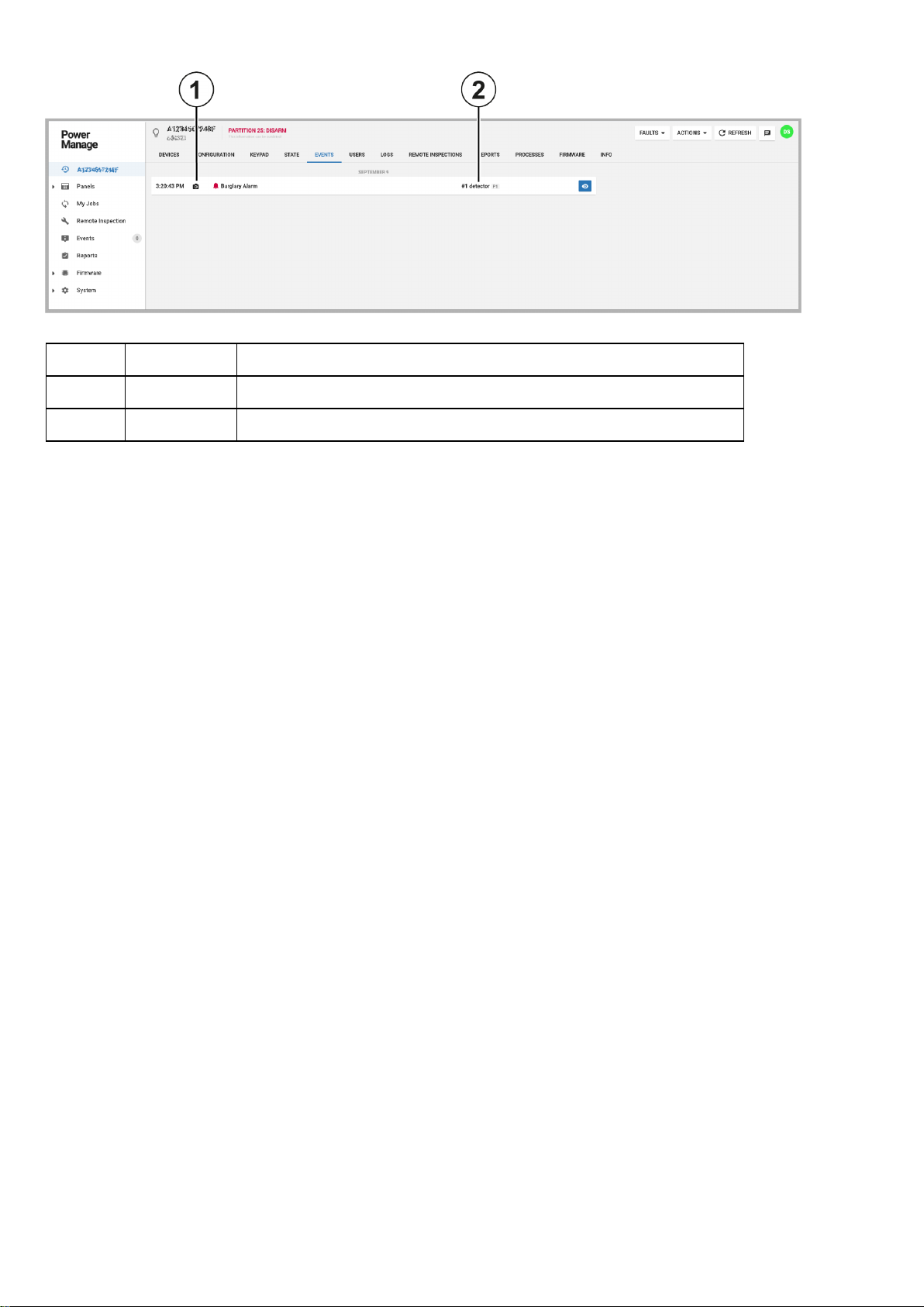
Figure: PIR camera zone association event
Table 2. Zone association event
Callout Name Description
1 Camera icon Indicates that video footage is available from an associated PIR camera.
2 Zone Indicates the zone number of the sensor.
- 13 -
Page 14

Associating a PIR camera with a sensor
Note:You can associate a PIR camera with sensors with a PSP 1.30 panel only.
1. To open a panel in the panel hub, on the Panels page, in the PANEL column, click the panel name.
2. On the DEVICES tab, click a PIR camera device.
3. In the examination pane, click CONFIGURATION. If the configuration parameters are not up to date, click REFRESH.
4. Scroll down to Camera X Zone Assign. The X stands for the PIR camera device zone number.
5. In a Zone Cam Trig field, enter the zone number of the sensor that you want to trigger the PIR camera to record video foot-
age.
6. Optional:Repeat Step 5 to associate the PIRcamera with up to seven additional trigger sensor devices.
7. To save the configuration in the panel, in the notification panel below the Devices tabs, click UPLOAD.
Using video on demand with ITv2 integration
The user or operator can record a short video clip after an alarm with video on demand through the ITv2 protocol integration.
In Neo and PSP panels, video on demand is available only if the FIBRO receiver channel is configured to the PowerManage
server. For PSP panels version 1.3 and later, you can use video on demand with the ITv2 integration channel.
PIR camera images during a system test
In a system test, Neo panels version 1.35 and later, and PSP panels version 1.30 and later, upload two images from each
PIR camera sensor. You can view the video footage in the PowerManage GUI.
If both the FIBRO receiver and the ITv2 integration channels direct to the PowerManage server, one system test event
appears in the PowerManage web application with the PIR camera video footage.
If the ITv2 integration channel only directs to the PowerManage server, two system test events appear in the PowerManage
web application. The first system test event, like in previous versions, does not have video. The second system test event
contains video footage from the PIR cameras.
- 14 -
Page 15
Upgrading 4G/LTE modems
You can upgrade 4G/LTE cellular modems for PowerMaster panels. The 4G/LTE modem comprises two parts that you can
upgrade separately, the GSM modem and the OTA (Over The Air) modem.
Before you can upgrade either the GSM modem or the OTA modem, technical support must upload the upgrade package to
the repository and attach it to the PowerManage server. The packages appear in the global FIRMWARE page and the local
FIRMWARE tab.
Note:To upgrade the GSM modem, choose the upgrade package that matches both your current version and the version that
you want to upgrade to. To upgrade the OTA modem, choose only the upgrade package that matches the version that you
want to upgrade to.
To mass upgrade the GSM modem or the OTA modem for multiple panels, see in Mass upgrading the firmware of a device.
To upgrade the GSM modem or the OTA modem for a single panel, see in Upgrading the firmware of an individual panel in the
panel hub.
You can see the 4G/LTE cellular modem on the DEVICES tab in the panel hub. The software version and RSSIalso display.
For more information see GSM modem and OTA modem in GSM modem and OTA modem on the devices tab.
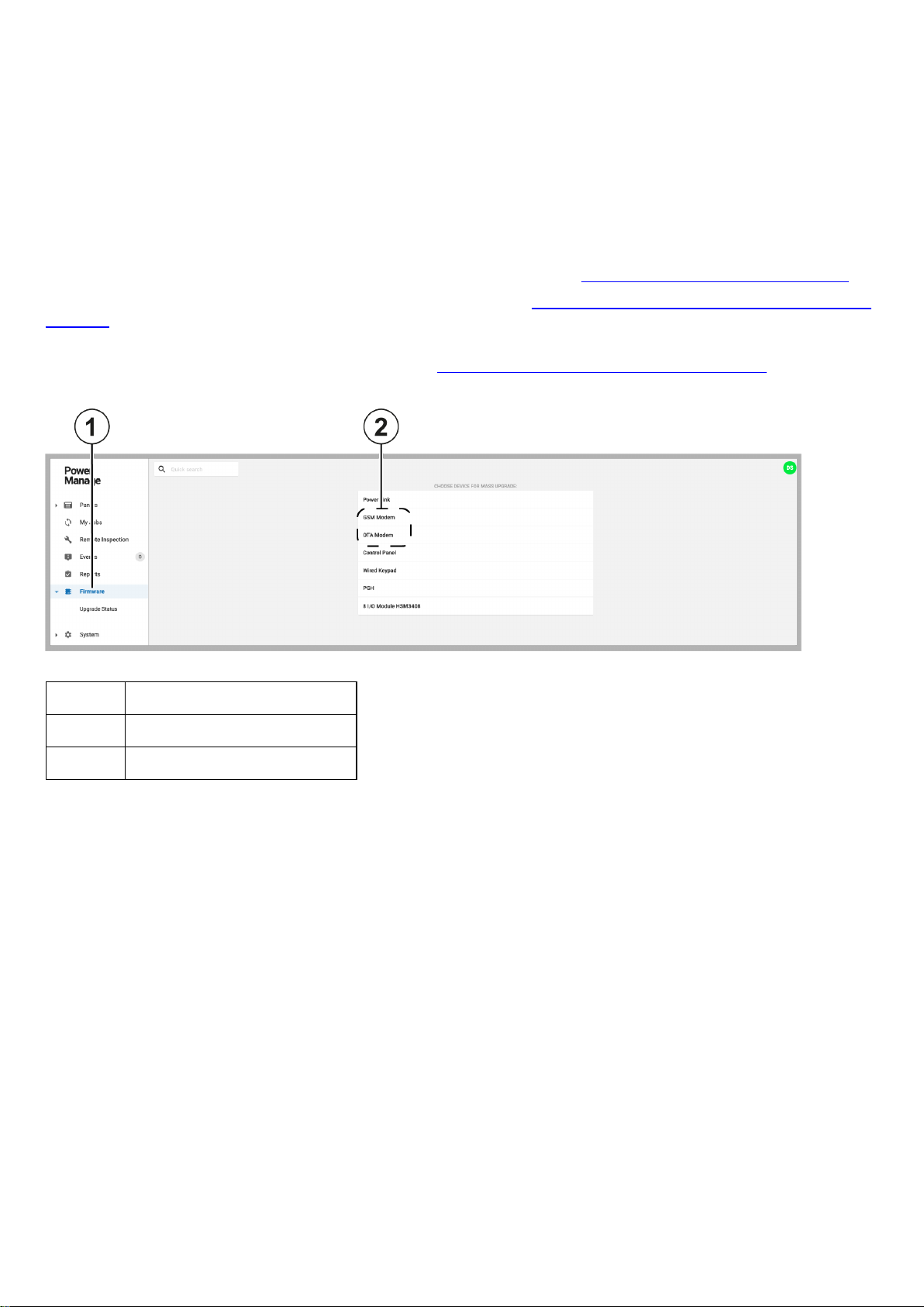
Figure: Global firmware page
Table 3. Global firmware page
Callout Name
1 Firmware page
2 GSM Modem and OTA modem
- 15 -
Page 16
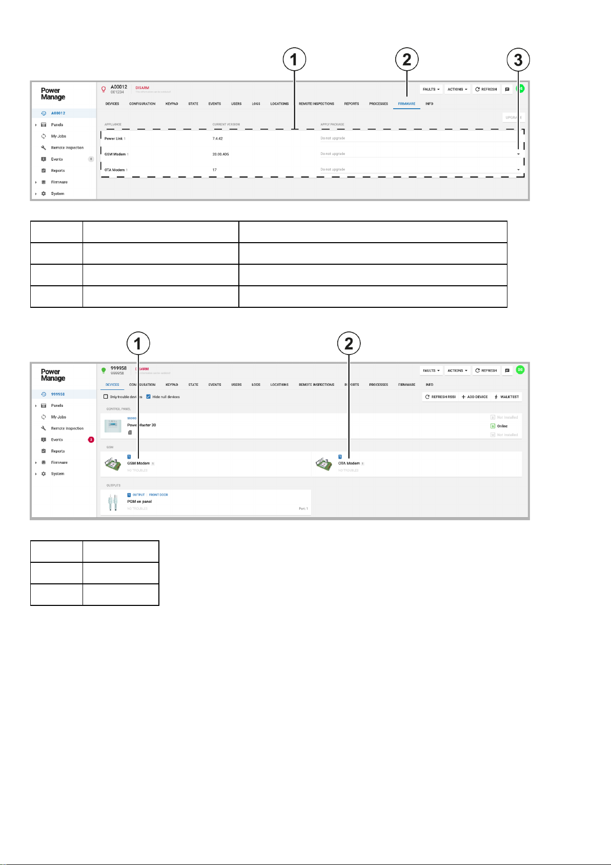
Figure: Local firmware page
Table 4. Local firmware page
Callout Name Description
1 Upgrade packages Select an upgrade package in the APPLY PACKAGE list
2 FIRMWARE tab FIRMWARE tab on the panels page
3 Upgrade package dropdown list Click to select an upgrade package from a dropdown list.
Figure: GSM modem and OTA modem on the devices tab
Table 5. GSM modem and OTA modem on the devices tab
Callout Name
1 GSM modem
2 OTA modem
- 16 -
Page 17
Interactive user management
The Interactive Users page includes additional interactive user management features. For more information, see Table 7.
For more information about the Interactive Users page, see Interactive Users page in Table 6.
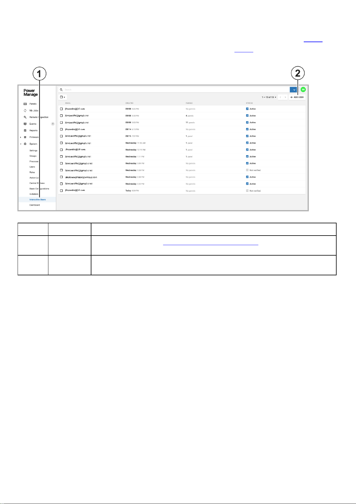
Figure: Interactive Users page updates
Table 6. Interactive Users page updates
Callout Name Description
1 Interactive
Users page
2 ADD USER Click to add a new user with an email address. The new user receives a two-factor authen-
For more information, see
tication verification email to enter in the ConnectAlarm app.
Navigating the Interactive users page
.
- 17 -
Page 18
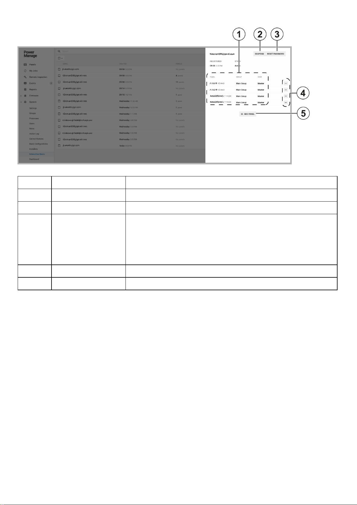
Figure: Interactive user management
Table 7. Interactive user management
Callout Name Description
1 SUSPEND Click to suspend the user.
2 RESET PASSWORD Click to reset the user's password.
3 Connected panels
Displays the panels the user is connected to.
l PANEL: Displays the name of the panel
l GROUP: Displays the panel group
l USER: Displays the type of user permissions the user has for the
panel
4 Remove panel button Click to remove a panel from the interactive user account
5 ADD PANEL Click to add a new panel to the interactive user account
- 18 -
Page 19
Panel search by customer information
You can search for a panel on the Panels page using the following information that is on the INFO tab:
l Customer name
l Customer email address
l Customer phone number
l Customer address
l Any comments posted on the INFO tab
For example, you can search for the panel in the following figure that contains the comment, short remark. For more
information, see Panel in Table 9 and Comment in Table 8. If you type short remark in the search bar on the Panels page,
the search results display the panels that contain the comment in the INFO tab of the panel. For more information, see
CUSTOMER INFO in Table 8.
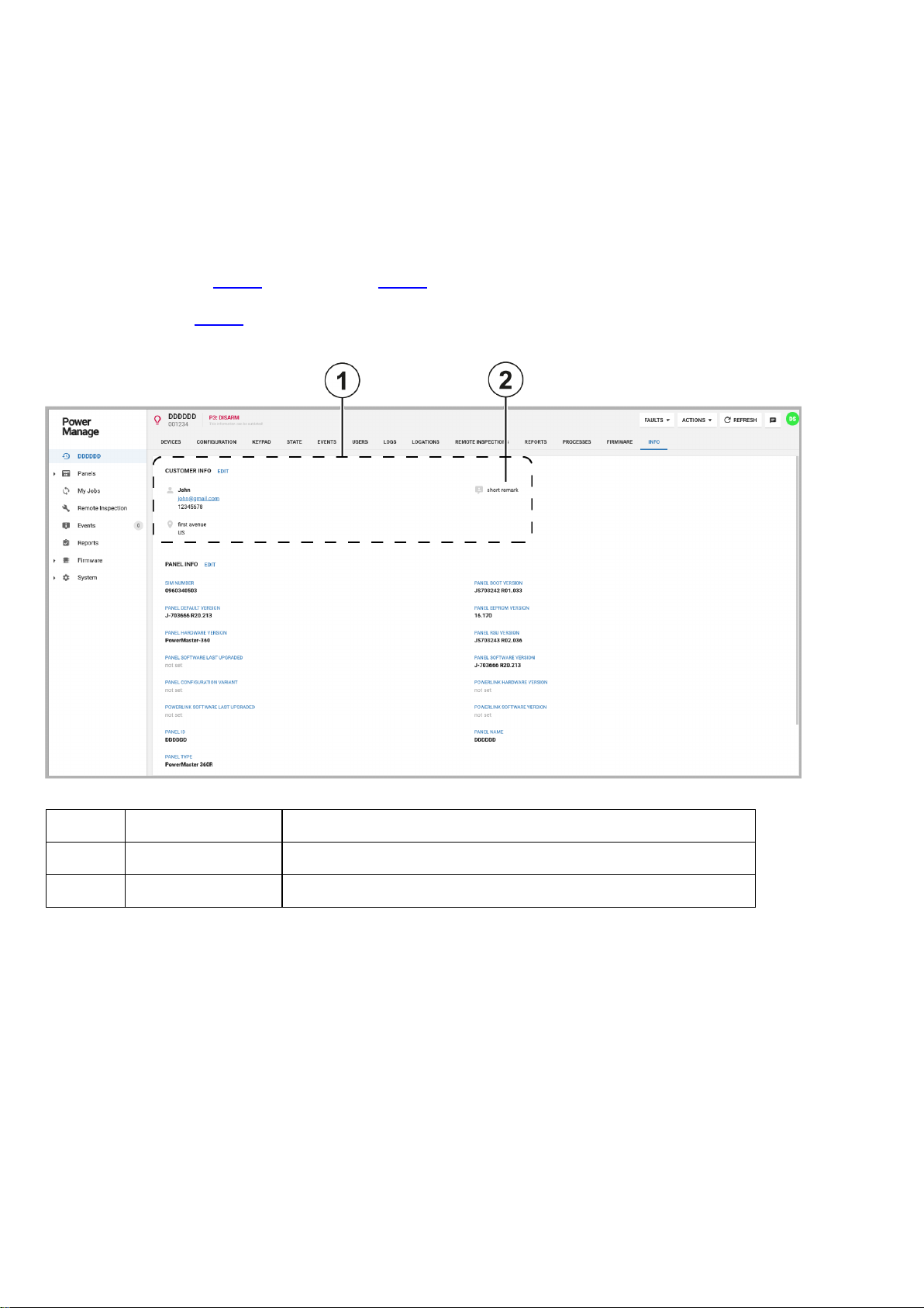
Figure: Customer information on the INFO tab
Table 8. Customer information on the INFO tab
Callout Name Description
1 CUSTOMER INFO Information about the customer that users can edit on the INFO tab.
2 Comment A comment entered by a user. Click
EDIT
to leave a comment.
- 19 -
Page 20
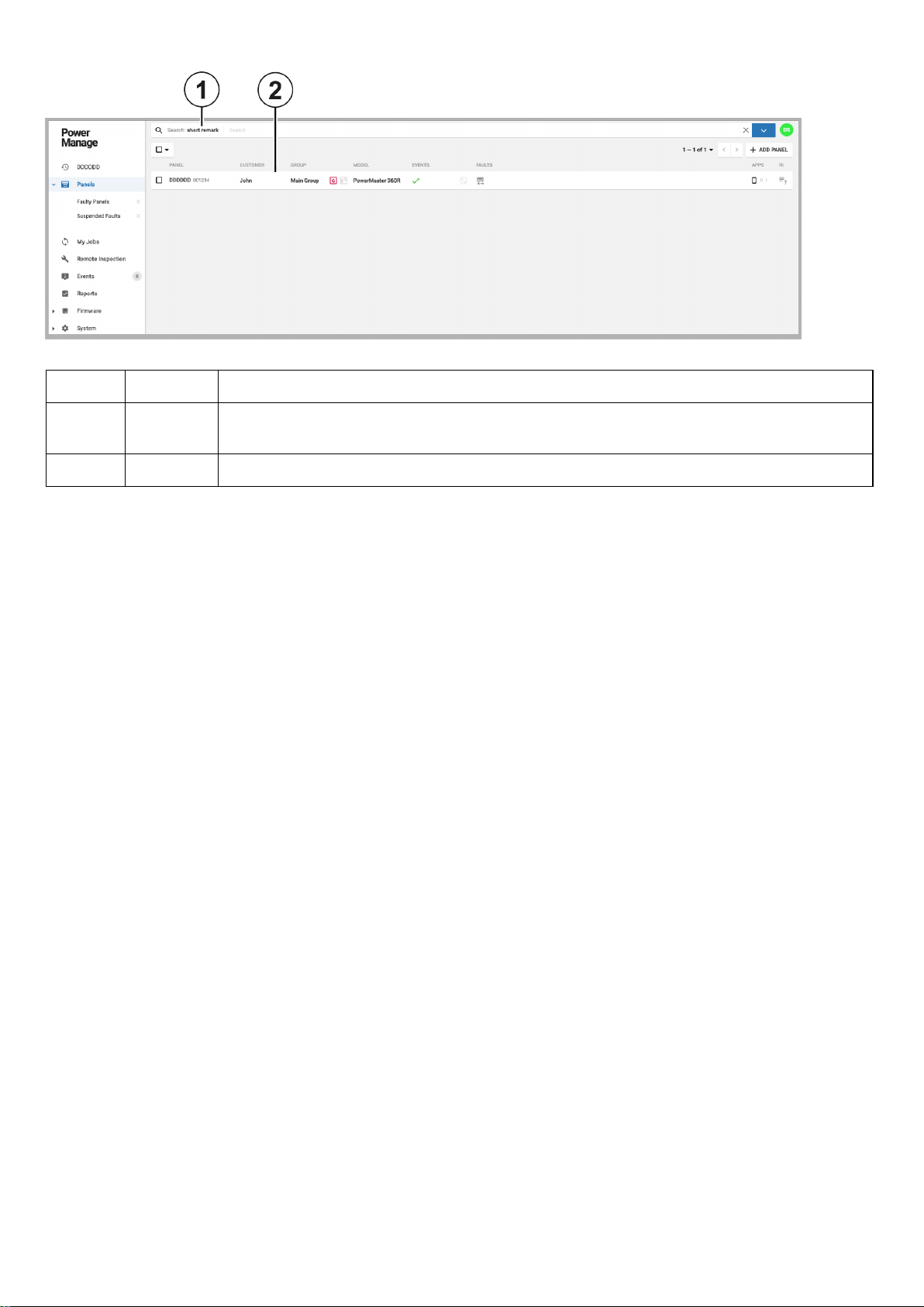
Figure: Searching for panels with customer information
Table 9. Searching for panels with customer information
Callout Name Description
1 Comment Type a comment to search the Panels page for any panel with the same comment left in the
panel's INFO tab.
2 Panel Panels that contain the search term in the panel's INFO tab appear in the search results.
- 20 -
Page 21
Authorization settings for interactive users
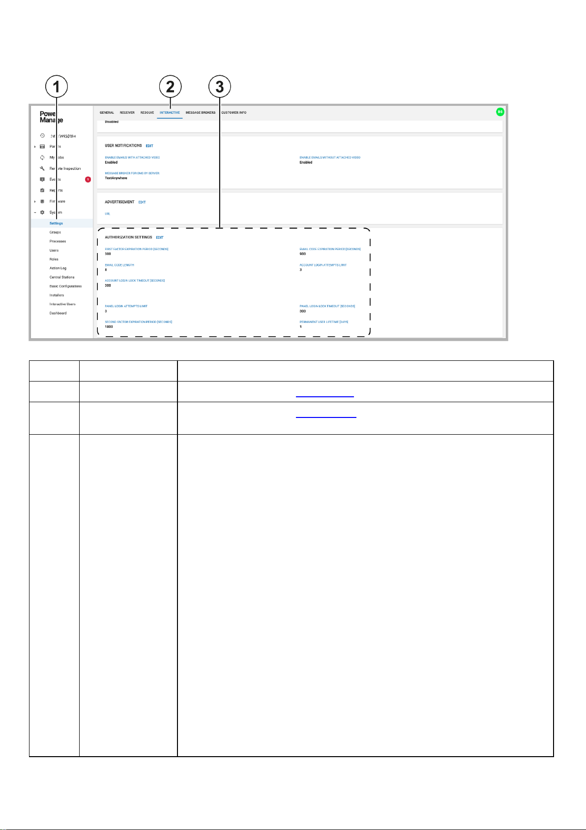
Figure: Authorization settings
Table 10. Authorization settings
Callout Name Description
1 Settings page For more information, see
2 INTERACTIVE
For more information, see
tab
3 AUTHORIZATION
SETTINGS
l FIRST FACTOR EXPIRATION PERIOD [SECONDS]:The time that a
user can stay logged on to the app when the AlarmInstall and ConnectAlarm
apps are minimized and running in the background
l EMAIL CODE LENGTH:The length of the verification email code that the
server sends to the user during the two-factor authentication sign up process
l ACCOUNT LOGIN LOCK TIMEOUT [SECONDS]:The length of time that
the user's account is blocked from a panel if the user enters incorrect twofactor authentication logon information for more times than the limit
l PANEL LOGIN ATTEMPTS LIMIT: The number of two-factor authen-
tication logon retries before the user's account is blocked
l SECOND FACTOR EXPIRATION PERIOD [SECONDS]: The length of
time that the AlarmInstall and ConnectAlarm app stay connected to a panel if
the app is minimized and running in the background.
l EMAIL CODE EXPIRATION PERIOD [SECONDS]:The length of time
that the two-factor authentication email verification code is valid.
Settings page
Interactive tab
.
.
l ACCOUNT LOGIN ATTEMPTS LIMIT:The number of two-factor authen-
tication logon retries before the user's account is blocked
l PANEL LOGIN LOCK TIMEOUT [SECONDS]:The length of time that
access to a panel is blocked if the user enters incorrect two-factor authentication log on information for more times than the limit
l PERMANENT USER LIFETIME [DAYS]: The number of days a user has a
permanent user status after successfully logging on to a panel. Permanent
users can log on to the panel, even if the panel is locked
- 21 -
Page 22
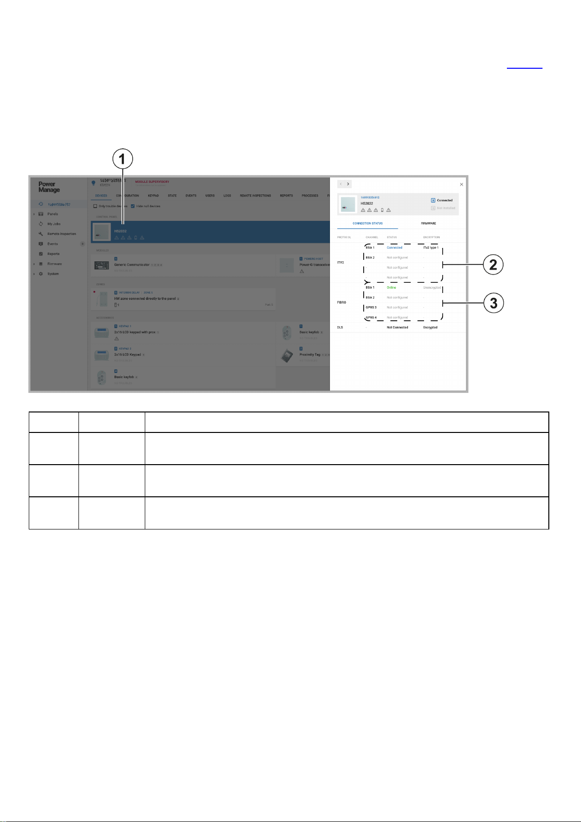
Panel connection channel status
To view the channel connection statuses of a panel, see ITv2 integration channels and FIBRO receiver channels in Table 11.
In the following figure, the Neo panel has four ITv2 integration connection channels. The first channel is connected to the
server and the remaining three channels are not configured.
The Neo panel also has four FIBRO receiver connection channels. The first channel is connected to the server and is online.
The remaining three channels are not configured.
Figure: Panel communication channel status on the DEVICES tab
Table 11. Panel communication channel status on the DEVICES tab
Callout Name Description
1 Selected
panel
2 ITv2 chan-
nels
3 FIBRO
channels
Click a panel to open the panel in the examination pane and view the connection channels on
CONNECTION STATUS tab.
There are four ITv2 integration connection channels.
There are four FIBRO receiver connection channels.
- 22 -
Page 23

Viewing panel connection channels
1. To open a panel in the panel hub, on the Panels page, in the PANEL column, click the panel name.
2. On the DEVICES tab, click the panel you want. On the CONNECTION STATUS tab, the panel channel connection
statuses display in the examination pane.
For more information on panel channel connection statuses, see Viewing panel connection channels.
- 23 -
Page 24

Reading the diagnostics of a panel
Read the diagnostics of a panel to view the panel power data.
Note: System diagnostics are available for Neo and PSP panels only.
1. To open a panel in the panel hub, on the Panels page, in the PANEL column, click the panel name.
2. From the ACTIONS list, click Read Diagnostic. A Read diagnostic info process starts in the MY PROCESSES pane.
For more information about the MY PROCESSES pane, see Navigating the MY PROCESSES pane.
3. When the process ends successfully, on the DEVICES tab, click the panel.
4. In the examination pane, to open the DIAGNOSTIC tab, click DIAGNOSTIC.
To ensure the data is up to date, repeat this procedure to refresh the diagnostic reading.
Figure: Starting a Read diagnostic process
Table 12. Starting a Read diagnostic process
Callout Name Description
1
2 Read Diagnostic Click to start a
Read diagnostic info
process
When you click
MY PROCESSES pane.
Read Diagnostic
Read diagnostic info
, a
Read diagnostic info
process.
process starts in the
- 24 -
Page 25

Figure: Panel diagnostic results
Table 13. Panel diagnostic results
Callout Name Description
1
2 Selected panel Click a panel to open it in the examination pane.
3 DIANOSTIC tab Click DIAGNOSTIC to view the panel's diagnostic information on the
Read diagnostic info
process
When you click Read Diagnostic, a
MY PROCESSES pane.
DIAGNOSTIC tab.
Read diagnostic info
process starts in the
- 25 -
Page 26
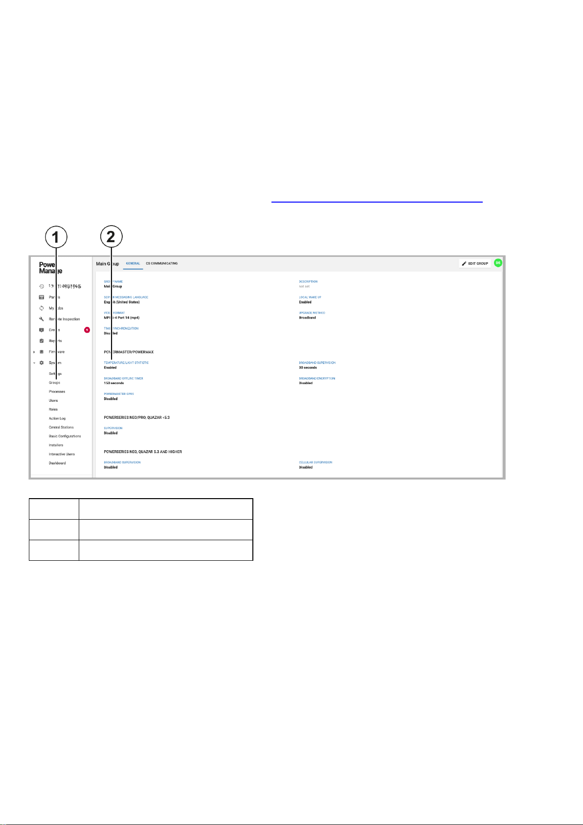
Enabling or disabling temperature and light statistics for a group of
panels with smart devices
Note: Temperature and light statistics are disabled by default for groups. Processing this data increases communication and
requires higher bandwidth.
1. In the navigation pane, click System, then click Groups.
2. Click the group you want.
3. Click EDIT GROUP.
4. Enable Temperature/light statistic.
5. Click SAVE.
To view the temperature or light statistics of a device, see Viewing device smart temperature or light readings.
Figure: Temperature and light statistic status
Table 14. Temperature and light statistic status
Callout Name
1 Groups page
2 TEMPERATURE/STATISTIC status
- 26 -
Page 27

Figure: Temperature and light graph on the METEO tab
Table 15. Temperature and light graph on the METEO tab
Callout Name
1 DEVICES tab
2 Selected smart device
3 Smart device icon
4 METEO tab
- 27 -
Page 28
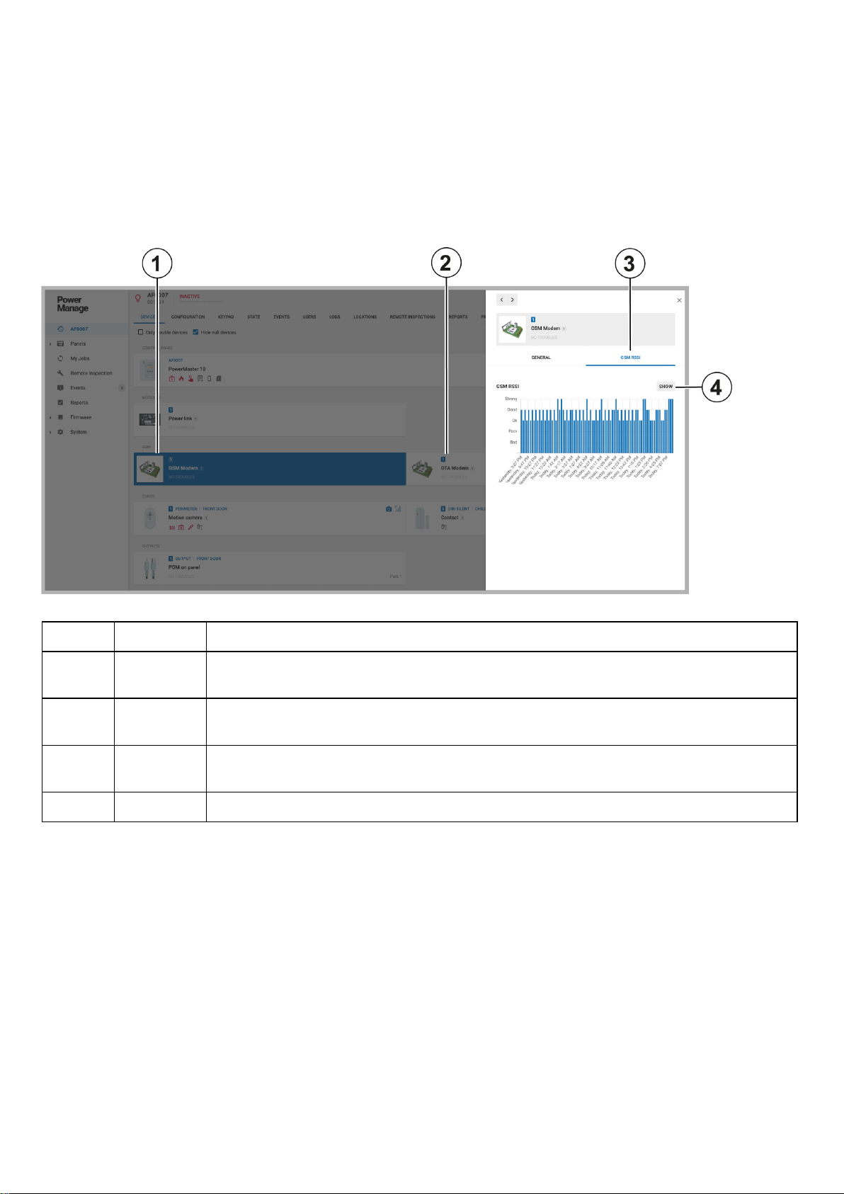
Viewing GSM signal statistics
1. To open a panel in the panel hub, on the Panels page, in the PANEL column, click the name of the panel that you want.
2. On the DEVICES tab, click the GSM Modem.
3. To view the GSM statistics, in the examination pane, click GSM RSSI.
Note:In PowerManage 4.8, GSM modem and OTA modem appear in the DEVICES tab, separate from the panel.
4. Optional: To open the GSM RSSI statistics dialog box, click SHOW. In the dialog box, you can view GSM RSSI statistical
graphs representing interactive time periods.
Figure: Viewing GSM signal statistics
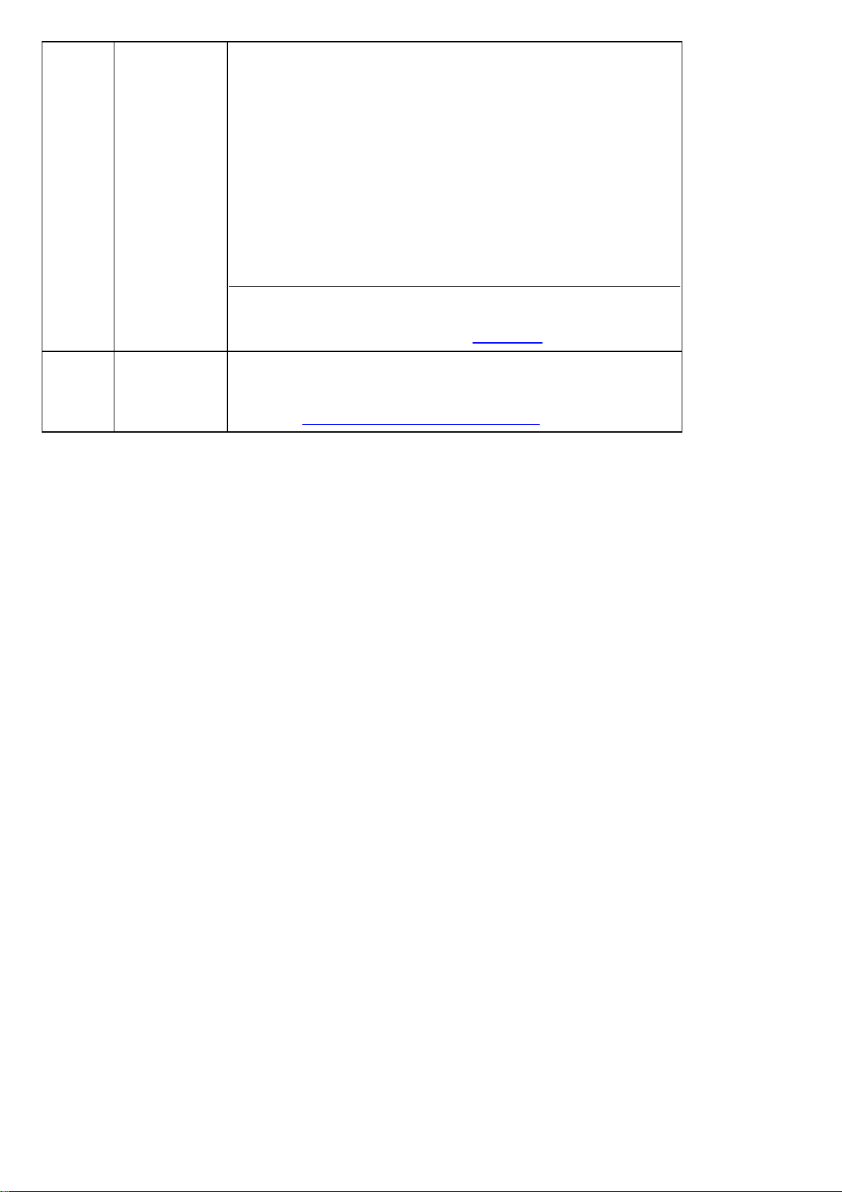
Table 16. Viewing GSM signal statistics
Callout Name Description
1 GSM
modem
2 OTA
modem
3 GSM
RSSI tab
4 SHOW Click to view a larger graph that is interactive.
A cellular communication modem
An 'Over the Air' software package in the 4G/LTE cellular modem. The OTA modem exists
only in PowerMaster panels.
GSM RSSI
Click
to view the connection strength of the cellular modem over time.
- 28 -
Page 29

Integration session access keys for type 2 ITv2 panels
Neo and PSP panels use an integration session channel. To encrypt the integration session channels, you require an
integration session key for each of the four channels.
To access the four keys, in your Neo or PSP panel menu, enter the following:
[*][8]<installer code>[851][423]/[450]/[477]/[504]
Note:In previous versions of PowerManage, the integration session access key was the same for all panels. From
PowerManage version 4.8, the integration session access key is unique to a panel and you cannot use the key for any other
panel.
- 29 -
Page 30

Customer information on the Panels page
On the Panels page, the CUSTOMER column displays the first name of the customer that is associated with that panel. For
more information, see CUSTOMER column in the following figure. Click the customer name to view more customer
information from the INFO tab. For more information, see Customer information in Table 18.
Figure: CUSTOMER column on the Panels page
Table 17. CUSTOMER column on the Panels page
Callout Name Description
1 Panels page Click to view the connected panels
2 CUSTOMER column Displays the customer's first name
3 Customer information
Click the customer's name to view the following customer information:
l Customer name
l Customer email address
l Customer phone number
l Customer address
l Any comments posted on the INFO tab
Figure: INFO tab information in the CUSTOMER column
Table 18. INFO tab information in the CUSTOMER column
Callout Name
Description
1 Customer information Appears if you click the customer name. This information populates the INFO tab.
- 30 -
Page 31

Configuring the removal of events, processes, and reports from the
server in rotation
Set the rotation time period to remove events, processes, or reports from the server.
1. In the navigation pane, click System, then click Settings.
2. On the RESOLVE tab, in the ROTATION pane, click EDIT.
3. Optional: In the Events Age [DAYS] field, enter the number of days you want events to stay on the server before the sys-
tem removes them.
4. Optional: In the Process Age [DAYS] field, enter the number of days you want processes to stay on the server before the
system removes them.
5. Optional: In the Report Age [DAYS] field, enter the number of days you want reports to stay on the server before the sys-
tem removes them.
Figure: Rotation of events processes and reports on the RESOLVE tab
Table 19. Rotation of events processes and reports on the RESOLVE tab
Callout Name
1 Settings page
2 RESOLVE tab
3 ROTATION pane
- 31 -
Page 32

Server CUSTOMER INFO tab in the system settings
You can add or edit the following server administrator customer information in the CUSTOMER INFO tab in the system
settings:
l Customer name
l Address
l Web admin email address
Note:The email address in WEB ADMIN EMAIL is also the default super admin logon email address. The default
email address is admin@tycomonitor.com.
l Personal email address
l Point of contact name
l Phone number
Figure: Customer info tab in the system settings
Table 20. Customer info tab in the system settings
Callout Name
1 Settings page
2 WEB ADMIN EMAIL
3 CUSTOMER INFO tab
- 32 -
Page 33

Getting started
Introduction to PowerManage
Use the PowerManage service management platform to manage panels remotely in real time from a central monitoring station
(CMS) and with an internet protocol (IP) receiver.
Advantages of the PowerManage server:
l Receiver: PowerManage serves as an IP receiver for regular events and video events.
l Resolve:PowerManage enables home control and services such as reports, tests and panel configuration.
l Interactive:PowerManage enables users and installers to access the panel with the mobile application.
Introduction to the PowerManage web help
The PowerManage documentation provides monitoring service provider operators and IT managers instruction on managing
the following:
l The PowerManage service management platform
l Security alarm panels
l Panel configurations
l Groups of monitored panels
l Alarms and events
l System tasks
Compatible systems
PowerManage supports the following security systems:
l Visonic PowerMaster and PowerMax panels
Note: Some PowerManage features do not exist in older panel versions.
l Neo panels with version 1.11 and later and communicators with version 4.11 and later
l PowerSeries Pro systems up to version 1.3
l SIA-IP protocol communication based monitoring systems
l Dual-path communicator
Supported NEO panels versions:
l HS2128: v.1.36
l HS2016: v.1.11, v.1.2, v.1.31, and 1.33.
l HS2016-4: v.1.11, v.1.2, v.1.31, and 1.33.
l HS2032: v.1.11, v.1.2, v.1.31, and 1.33.
l HS2064: v.1.11, v.1.2, v.1.31, and 1.33.
Supported NEO communicator versions:
l TL2803GRE: v.5.41, v.4.11 (Ethernet only), v.5.01, v. 5.02, v.5.03, v.5.11, v.5.21, and v.5.3.
Supported PSP panels versions:
l HS3248: v.1.30.xx.xxx
l HS3032: v.1.02.01.001, v.1.11.01.002, and v.1.20.01.029.
l HS3128: v.1.02.01.001, v.1.11.01.002, and v.1.20.01.029.
l HS3248: v.1.02.01.001, v.1.11.01.002, and v.1.20.01.029.
Supported Visonic panels versions:
l PowerMaster-10: v.20.213/214, v.E20.214, v.L20.213, v.R19.412, v.K18.415, v.K18.055, v.K17.133, v.K16.012,
and v.I12.012.
- 33 -
Page 34

l PowerMaster-30: v.20.213/214, v.E20.214, v.L20.213, v.R19.412, v.K18.415, v.K18.055, v.K17.133, v.K16.012,
and v.I12.012.
l PowerMaster-360R: v.20.213/214, v.E20.214, v.L20.213, v.R19.412, v.K18.415, v.K18.055, v.K17.133, v.K16.012,
and v.I12.012.
l PowerMax PRO (C17.108)
PowerLink software versions:
l x.x.94.14
l x.x.93.17
l x.x.92.6
l x.x.46
l 7.4/5.27
Regular tasks to perform
l View and handle security and maintenance events. For more information, see Events page.
l Configure panels
l Diagnose and resolve panels
l Perform inspections, reports, and firmware upgrades. For more information about remote inspections, see Remote
inspections page. For more information about reports, see Reports page. For more information about firmware
upgrades, see Firmware page.
l Enable and disable homeowner and installer access to panels by using the user and installer mobile applications. For
more information, see user and installer apps in Navigating the Installers page.
l Add new panels to the server. For more information, see Adding a panel to the server.
- 34 -
Page 35

Setting up PowerManage
1. Plan the permission framework.
a. To group similar panels together and perform common actions to large groups of panels at once, create panel groups. For
more information on adding groups see Adding a new group.
b. Add server users. For more information, see Adding a new user.
c. To define the permissions of the server users, create roles to connect to each server user. For more information on cre-
ating roles and defining permissions, see Roles page.
2. To organize the user hierarchy of the server, define the administrator and the operator accounts on Users page.
Server parameter configuration methods
Configure the PowerManage server parameters with one of the following methods:
l The PowerManage application web site. For more information, see Configuring the server parameters by the web
application.
l The PowerManage Management Console. For more information, see Configuring the server parameters by the con-
sole.
Related topics
PowerManage architecture
Navigating the user interface
Navigating the MY PROCESSES pane
Using the search filter
Logging on to the PowerManage system
- 35 -
Page 36

PowerManage architecture
Figure: PowerManage architecture
Table 21. PowerManage architecture components
Callout Name Description
1 PowerManage
The PowerManage server
server
2 Receiver
The PowerManage receives events from the panels by IP or GPRS
communication and displays them on the server. The PowerManage
then forwards the events to automation applications or central
monitoring stations using the following protocols:
l Panels to server protocols:
l Standard protocols, such as SIA, CID, and FIBRO
l Proprietary protocols, such as power-net
l Server to automation protocols:
l Standard protocols, such as MLR-2 or FEP
l Proprietary protocol, such as VISNAP
3 Resolve Enables the server operator to control and view panel parameters, as
well as run tests and create reports
4 One-click Click to view recent events and any related images or video clips in
PowerManage
5 VDCP pro-
tocol
Enables the operation of large numbers of panels simultaneously and
enables PowerManage to connect to third party applications through a
two-way interface. The two-way interface is a Python based program.
6 Interactive
app
The user application enables homeowners to perform most operations
that are permitted to a panel user. For example, homeowners can view
the security system status, remotely arm or disarm the system,
receive image verification and view historical logs on a mobile device or
remote PC.
The installer mobile application enables the installer to view and
configure the panel remotely without visiting the customer's residence.
- 36 -
Page 37

Navigating the user interface
Figure: Navigating the user interface
Table 22. User interface elements
Callout Name Description
1 PowerManage
logo
Click to view the version, build number, local time and timezone of the
server. The PowerManage software version displays beside the PowerManage logo.
To change the PowerManage logo to a custom logo, contact technical
support.
2 Navigation
To view a page, click the page name in the navigation pane.
pane
If a menu option does not display for a server user, it can be due to any
of the following reasons:
l The required privileges are not defined in the user's role. For
l The PowerManage server has licensing logic that removes
3
Search
bar Search a page by using by free typing or a number of search filter
options. For more information, see
4 User icon
Click the user icon to open a list with the following options:
l Settings: To define the following settings, from the user icon
more information on roles, see Roles page.
some of the server's functionality. If pages are missing and it
is not due to undefined privileges, contact technical support.
Using the search filter
.
list, click Settings:
l Language for the server user
l Temperature standard units
l Theme: light or dark
- 37 -
Page 38
l Automatic log out timeout
l Alarm supervision settings
l Turn on or off app notifications and notification sounds
l Edit Profile: To edit the phone number and country of the
server user, from the user icon list, click Edit Profile.
l Change Password: To change the password of the server
user, from the user icon list, click Change Password.
l Help: To view the PowerManage web help, from the user icon
list, click Help.
l Logout: To log out of the PowerManage web user interface,
from the user icon list, click Logout.
The user icon displays the initial of the first name of the user that is
logged on. The initialsDSdisplay for the default super admin user icon.
For more information about users, see
Users page
.
5
MY
PROCESSES
pane
MY PROCESSES
The
pane displays the processes that are currently
running and the most recently finished processes that were initiated by
the user's computer. For more information about the
pane, see
Navigating the MY PROCESSES pane
MY PROCESSES
.
- 38 -
Page 39

Figure: Navigation pane
Table 23. Navigation pane pages and lists
Callout Name Description
1
2
3
4
Panels
page
My Processes
page
Remote
inspection
page
Events
page
Manage the panels that are enrolled on the server. You can enroll panels
manually or automatically. To enroll a new panel, see
server
. For more information about
To examine a panel in the panel hub, on the
name. For more information about the panel hub, see
The sub-menus
preset saved search filters that are related to the
delete the saved search filter.
View all of the processes that the logged in user initiates. The My Processes
page joins processes that generate together.
To view processes initiated by all users and more information on the actions
that can be performed, see Processes page.
Open the
tests for the panels that are enrolled in the server. For more information,
Remote inspections page
see
To run or view a remote inspection for an individual panel, open the panel
in the panel hub and go to the
information, see
Events
The
enrolled panels. For more information, see
Faulty Panels
Remote inspection
Remote inspections tab
page displays all of the events that are received from all
Panels
Suspended Faults
and
page to view, run, and schedule health
.
REMOTE INSPECTIONS
page, see
Panels
.
Events page
Adding a panel to the
Panels page
page, click the panel
Panel hub
are examples of
Panels
.
.
page. ClickXto
tab. For more
.
5
6
7
Reports
page
Firmware
page
System
list
View, create, stop, and remove reports on the
in CSV or PDF format. For more information about reports, see
page
.
If you create a report on the
that are enrolled on the server. To create a report for an individual panel,
Creating a new report on the Panels page
see
Mass upgrade the firmware of a group of panels or devices on the
ware
page. For more information, see
To manage issues related to the server, select the required page from the
System
groups, processes, users, roles, action log, central stations, basic con-
list. Manage server issues related to the following categories:
Reports
- 39 -
page, the report runs on all panels
Firmware page
Reports
.
page. Reports are
Reports
Firm-
.
Page 40

figurations, installers, interactive users and dashboard. For more information, see
Table 24
.
- 40 -
Page 41

Figure: Navigating the System list
Table 24. System list pages
Callout Name Description
1 Settings
2
3
4
5
6
7
Groups
Processes
page
Users
page Create, remove, suspend, or enable server users on the
Roles
page Manage the roles types that you can assign to users. For more inform-
Action log
page
Central stations
page
page Use the settings page to set up server configuration parameters. For
more information, see
page Manage panel groups on the
panels that share the same configuration settings. For more information, see
View a list of all the processes that run on the server on the
cesses
For more information, see
ation, see
View all of the actions made by the user that is logged on. The
Actions log
Failure
failure, it indicates if the action started with success or failure.
PowerManage can also function as a receiver that forwards events
from security panels to automation servers or central stations. Manage the information panels communicate on the
page. For more information, see
Groups page
page. For more information, see
Roles page
page logs actions in chronological order. A
status does not mean that an action finishes with success or
Settings page
Groups
.
Users page
.
Central stations page
.
page. A group is a collection of
Pro-
Processes page
.
Central stations
.
Users
Success
.
page.
or
10
11
8
9
Basic configurations
page
Installers
Interactive
users page
Dashboard
page
Manage basic configurations that you can push to multiple panels at
once in the
Basic configurations page
page Manage installer access to the panel with the mobile application on the
Installers
Manage user access to the panel with the mobile application on the
Interactive users
page
View the overall statistical data from the server in a visual format on
Dashboard
the
Basic Configurations
.
page. For more information, see
page. For more information, see
.
page. For more information, see
- 41 -
page. For more information, see
Installers page
Dashboard page
.
Interactive users
.
Page 42

Related topics
Navigating the MY PROCESSES pane
Using the search filter
- 42 -
Page 43

Navigating the MY PROCESSES pane
The MY PROCESSES pane displays the most recent processes run by the user on the current computer. To view more
information about a process, in the MY PROCESSES pane, click the process.
For more information about all processes on the server, see Processes page. For more information about the processes of an
individual panel, see Processes tab.
Figure: Navigating the MY PROCESSES pane
Table 25. MYPROCESS pane interface elements
Callout Name Description
1 Process
status
color
2
The colored line under each process signifies the following statuses:
l Gray: The process has not started.
l Yellow: The process is in progress.
l Green: The process finishes successfully.
l Red: The process fails.
Click to remove all of the processes from the processes pane.
3 Click to remove a process from the processes pane.
Related topics
Navigating the user interface
Using the search filter
- 43 -
Page 44

Using the search filter
Filter the search by one of the following methods:
l Type a search term in the Search bar and click SEARCH.
l Select one or more key-value pairs in the Search list.
l Begin to type key-value pairs and click the desired option in the auto-complete list.
Figure: Navigating the search filter selection
Table 26. Search interface elements
Callout Name Description
1 Selected fil-
ters
2
Search
bar
3 Cancel
search
4
Search
list
button
5
6
SEARCH
SAVE
CURRENT
SEARCH
When you select a
Search
the
bar as a filter. Filter the search to return a match of one or
more key-value pairs that you set in the
Click a filter in the
Enter a term or key-value pair in the
Search
Search
list key-value pair, the key-value pair saves in
Search
list.
bar to remove it from the search.
Search
bar to search the selected
page.
Click the
Search
bar or start to enter a key or value in the
Search
bar and
a list of options appears. Select a key and pair from the auto-complete list
and the key-value pair saves in the
Search
bar.
Click to cancel a search.
Click to filter the search with one or more key-value pairs.
Click the search bar to select a key and a related value, one at a time.
Click to search the selected page with a filter or search.
Click to save your key-value pairs as a preset search. The saved search
appears in the navigation pane in a drop-down list under the related page
name.
Faulty Panels
searches that appear under the
Suspended Faults
and
Panels
are examples of preset saved
page in the navigation pane. To
delete a saved search on the navigation pane, click theXnext to it.
7 Selected
values
Click a search value to add it to the selected filters in the search bar. You
can only select one value per key. The key-value pairs change depending
on the page that is selected.
Use the scroll bar to scroll horizontally through the search keys and values.
- 44 -
Page 45

Related topics
Navigating the user interface
Navigating the MY PROCESSES pane
- 45 -
Page 46
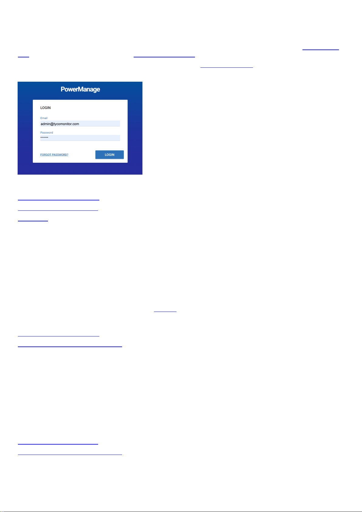
Logging on to the PowerManage system
Access the PowerManage system with an email address and password. A user's email address and password identify the
user and are set when the user is added to the server. For more information on adding a user to the server, see Adding a new
user. To change a user's email address, see Editing user information.
For more information about logging in as the Default Super Admin, see Default super admin.
Figure: PowerManage logon
Related topics
Resetting a forgotten password
Changing your logon password
Users page
Changing your logon password
1. Click the user icon in the upper-right of any page.
2. From the User list, select Change Password.
3. Enter your current password in the Current Password field.
4. Enter your new password in the New Passwordand Confirm Password fields.
5. Click SAVE.
Note: To change the password of a server user with fewer permissions, navigate to the user on the Users page and click the
edit user icon. For more information, see Edit user in Table 61.
Related topics
Resetting a forgotten password
Logging on to the PowerManage system
Resetting a forgotten password
1. From the LOGIN dialog box, click FORGOT PASSWORD in the lower-left corner.
2. Enter your registered email address in the email field and click REMIND.
3. Log on to the email account of the address you provide and retrieve your new password.
Note:If you cannot find the email with the password reset in your inbox, check your spam folder.
4. Log on with your email address and new password.
Related topics
Changing your logon password
Logging on to the PowerManage system
- 46 -
Page 47

Configuring the server parameters by using the PowerManage web application
1. Open a web browser.
Note: The PowerManage server does not support Internet Explorer or Opera.
2. Enter the IPaddress or the DNS name of your PowerManage server. For example, enter: https://<server URL
name>.
3. To log on, enter the default username and password:
l Username: admin@tycomonitor.com
l Password: Admin123
Important: Change the default admin password as soon as possible. For more information, see Changing your logon
password.
Configuring the server parameters by using the PowerManage Management Console
Note:Use the Management Console to configure the server in the initial stages of the panel installation. It is also mandatory
to use the Management Console to configure the internet connection during the setup stages. The Management Console is
also referred to as MMI.
1. To log on to the PowerManage server, use an SSH program such as PuTTY, or use the web browser URL: <power-man-
age DNS name>:2200.
2. Enter the default username,mmi.
3. Enter the default password, visonic.
Note: If you log on for the first time, you are prompted to enter a new password after this step.
- 47 -
Page 48

Panels page
Navigating the Panels page
You can view a list of all of the panels that are enrolled on the server on the Panels page.
Figure: Navigating the Panels page
Table 27. Panels page interface elements
Callout Name Description
1 Last panel
Click to view the last panel viewed in the panel hub
viewed
2 Panel filter
Customized search filters that you create for the
here. For more information, see
The preset
appear by default. Click
Faulty Panels
Faulty Panels
display panels with faults. Click
Using the search filter
Suspended Faults
and
to filter the panels page to only
Suspended Faults
page to only display panels with suspended faults.
3 Check box Select the check box of one or more panels to enable
4 Panel name
and account
FAULTS,CREATE REPORT
Displays the panel name and panelID. By default, the panel name is
the panel ID. To change this to a custom name, edit the panel
RUN INSPECTION
, and
information in the panel hub. For more information, see EDIT in Table
30. For more information on changing the panel name or account, see
Editing basic panel and customer information.
Note: For Neo panels, the panel ID is the integration identification
number. To find this number, enter [851][422] in the panel keypad.
Panels
page appear
.
search filters
to filter the panels
SERVICE
.
,
Select the panel name to open the panel in the panel hub. For more
information about the panel hub, see
5
SERVICE
To perform an action on one or more selected panels, from the
Panel hub
.
SERVICE list, select one of the following options:
l Change Group
l Refresh State
l Refresh configuration
l Push Basic Configuration
- 48 -
Page 49

l Trigger Discovery
l Remove
For more information on servicing panels, see Servicing panels.
6
FAULTS
7 CUSTOMER
column
8 Customer
information
To enable
SERVICE
, select the check box of one or more panel rows.
To perform an action on one or more selected panels, from the
FAULTS list, select one of the following options:
l Mark for service
l Reassign
l Resolve faults
l Suspend faults
l Resume faults
For more information on servicing panels, see Servicing panels.
To enable
FAULTS
, select the check box of one or more panel rows.
Displays the customer's first name. Click the customer's name to view
more customer information. For more information,
Customer information
Click the customer's name to view the following customer information:
l Customer name
l Customer email address
l Customer phone number
l Customer address
.
9
CREATE
REPORT
10
GROUP
column
11
RUN
INSPECTION
12 Connection
status
l Any comments posted on the INFO tab
Click to create a new report for one or more selected panels. For more
information about creating a report, see
ing a new report on the Panels page
To enable
CREATE REPORT
.
, select the check box of one or more
Creating new reports
and
Creat-
panel rows.
The group that the panel connects to displays in the
For more information about groups, see
Groups page
GROUP
.
column.
Click the group name to open the group hub. For more information
about the group hub, see .
Click to create a new inspection for one or more selected panels. For more
information about creating an inspection, see Creating a remote inspection
for a batch of panels and Scheduling a remote inspection for an individual
panel.
To enable RUN INSPECTION, select the check box of one or more panel
rows.
The G icon represents a GPRS or cellular connection and the B icon
represents an Ethernet or broadband connection. The color of an icon
represents the following information:
l If an icon is gray, no communication channel is present.
l If an icon is green, the communication channel is present and the
server receives keepalive messages from the panel.
l If an icon is blue, there is an open connection between the panel
and the server.
l If an icon is red, the communication channel is present but the
server does not receive keepalive messages from the panel.
l If an icon is black, keepalive messages are disabled in the panel's
- 49 -
Page 50

13 Panel model
group.
Note:
l You can only disable keepalive messages for Neo panel groups.
l The icon, Bg, indicates that the cellular connection is through an
Ethernet board.
The model of the panel
14
EVENTS
column
15
FAULTS
column
16 Search bar
17 User and
installer apps
EVENTS
The
column contains a summary of alarm and alert events.
The bell symbols indicates an alarm and the warning symbol indicates
an alert. For more information on events, see Event severity in
48
.
Table
Click the bell symbol to view a list of alarms from the panel and click
the warning symbol to view a list of alerts from the panel.
If there are no events, or all events are resolved, a green check mark
displays.
FAULTS
The
column displays any faults that affect the panel.
Hover over a fault icon to see a detailed description of the fault. Click a
fault to view a list of all faults from the panel.
If a panel is marked for service, a user icon appears to left of the
FAULTS
column with the initial of the user that is assigned to service
the panel. For more information about marking or reassigning a panel
for service, see
Marking a panel for service in the Panels hub
signing one or more panels that are marked for service
.
and
Reas-
In the search bar, search for a panel with the key-value pairs or by typing a
search term. You can also type a search term to find a panel with private
data, such as name, phone number, email address, and home address,
that is available in the INFO tab of a panel in the panel hub.
Click to open the user and installer apps dialog box and perform one of
the following actions:
l To allow a user to access the application by using the mobile
application, turn on User App.
l To disallow a user to access the application by using the
l To allow an installer to access the application by using the
l To disallow an installer to access the application by using the
18
ADD PANEL
Click to add a new panel to the server. For more information on adding a
panel to the server, see
19
RI
column
TheRIcolumn displays the status of the last remote inspection.
Click the RI icon to open the panel on the
tab in the panel hub. For more information about
INSPECTIONS
Related topics
Servicing panels
Adding panels to the server
Adding a panel to the server
Assigning a panel to a different group
Creating a new report on the Panels page
mobile application, turn off User App.
mobile application, turn on Installer App.
mobile application, turn off Installer App.
Adding panels to the server
REMOTE INSPECTIONS
REMOTE
tab, see
Remote inspections tab
.
.
- 50 -
Page 51

Marking one or more panels for service on the Panels page
Pushing a basic configuration to one or more panels
Reassigning one or more panels that are marked for service
Refreshing a panel configuration
Resolving faults in one or more panels
Suspending faults in one or more panels
- 51 -
Page 52
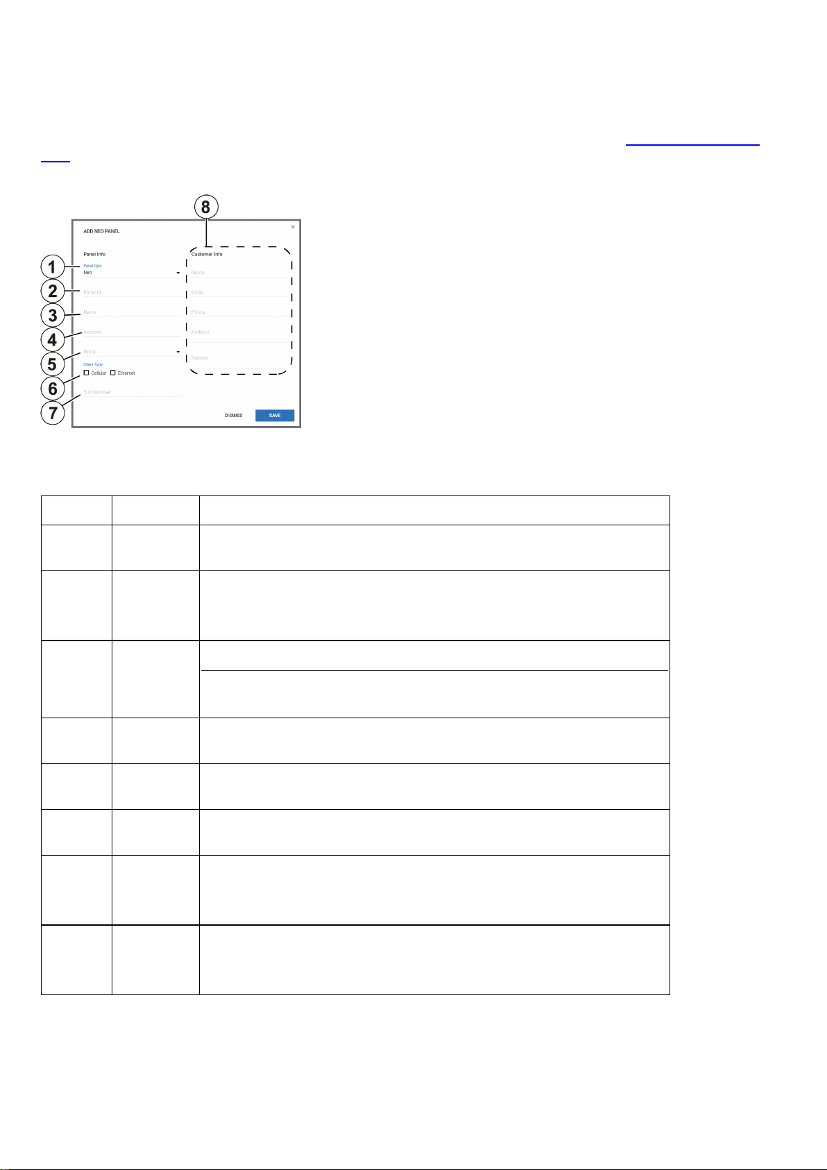
Adding panels to the server
Add a panel to the server on the Panels page.
Note: By default, panels auto-enroll on the server. To disable auto-enroll, contact technical support.
To add a panel, click ADD PANEL on the Panels page. For more information, see ADD PANEL in Navigating the Panels
page.
Figure: ADD PANEL dialog box
In the ADD PANEL dialog box, enter the panel information. See the following definition list for descriptions of the dialog box
fields:
Table 28. ADD PANEL dialog box elements
Callout Name Description
1
2
3
4
5
6
7
Panel
type
Panel Id In the Panel ID field, enter the panel identification number.
Name
Account
Group
Client
Type
SIM number
From the
Note:For Neo panels, enter the integration identification number in panel
installer menu:[851][422].
In the
The panel name identifies the panel to mobile application users. If no panel
name is entered, the panel ID appears instead.
To connect the panel to an automation or central station, enter the ID number of the automation or central station in the
From the
with.
Select or clear the
panel connects to the server. You can select
In the SIM number field, enter the number of the SIM card in the panel. The
number is used to send a wake-up SMS to the panel.
Panel type
Name
field, enter a name for the panel.
Group
list, select the panel type.
Account
list, select the group that you want to associate the panel
Cellular
and
Ethernet
check boxes to define how the
Cellular,Ethernet
field.
, or both.
Note: The SIM number is equivalent to a phone number.
8
Customer
Info
Enter the customer's information in the Name, Email, Phone, Address,
and Remark fields.
Note:Apart from the Email field, this information is stored and not used.
- 52 -
Page 53

Adding a panel to the server
1. In the navigation pane, select Panels.
2. On the Panels page, click ADD PANEL.
3. Enter the required information in the ADD PANEL dialog box fields. For more information on the ADD PANEL dialog box
fields, see Adding panels to the server.
4. Click SAVE.
Related topics
Servicing panels
Navigating the Panels page
- 53 -
Page 54

Servicing panels
You can service an individual panel in the panel hub, or multiple panels at once in the Panels page. When servicing a panel
with the SERVICE or FAULTS lists, see the following definitions:
Table 29. Panel servicing options
Action Description
Change
Group
Refresh State
Refresh Configuration
Push Basic
Configuration
Trigger Discovery
Remove Remove one or more panels from the server
Mark for service
Reassign
Move one or more panels from one group to another. For more information about
groups, see
Refresh the most up-to-date information for one or more panels, such as the faults
and panel status
Refresh the configuration parameters of one or more panels.
Push a custom basic configuration to one or more panels. For more information
about creating a basic configuration, see Creating a basic configuration from an
existing panel configuration.
Start a discovery process. During the discovery process, the server uploads configuration parameters from the panel to the server. You can also select a timeout to
determine how long the discovery process runs.
Note: If the server is set to auto-enroll and the panel is still connected to the
server, the panel enrolls again.
Mark one or more panels for service. If you mark a panel for service, the service icon
and the user icon of the user that the task is assigned to appear in the
column on the
user.
Assign the service task of one or more panels to a different server user
Groups page
Panels
page. The user icon features the initials of the assigned server
FAULTS
Resolve faults
Suspend
faults
Resume
faults
Related topics
Navigating the Panels page
Panel hub
Adding panels to the server
Adding a panel to the server
Assigning a panel to a different group
Creating a new report on the Panels page
Enabling automatic panel enrollment
Marking one or more panels for service on the Panels page
Pushing a basic configuration to one or more panels
Reassigning one or more panels that are marked for service
Remove the service icon and user icon from one or more panels that are marked
for service
Suspend a fault on one or more panels until a specified date. The fault icons
become gray in the
Resume suspended faults on one or more panels
FAULTS
column on the
Panels
page.
Refreshing a panel configuration
Resolving faults in one or more panels
Suspending faults in one or more panels
- 54 -
Page 55

Refreshing a panel configuration
1. In the navigation pane, select Panels.
2. Select the check box of one or more panels to refresh.
3. From the SERVICE list, select Refresh configuration.
A Download configuration process appears in the MY PROCESSES pane.
Related topics
Servicing panels
Navigating the Panels page
Pushing a basic configuration to one or more panels
1. In the navigation pane, click Panels.
2. Select the check box of one or more panels to configure.
3. From the SERVICE list, select Push Basic Configuration.
4. In the PUSH BASIC CONFIG dialog box, select a basic configuration.
5. Click PUSH.
Related topics
Servicing panels
Navigating the Panels page
Assigning a panel to a different group
1. From the navigation pane, select Panels.
2. Select the check box of one or more panels to reassign.
3. From the SERVICE list, select Change group.
4. In the ASSIGN PANEL TO GROUP dialog box, select a group from the Group list.
5. Click SAVE.
Related topics
Servicing panels
Navigating the Panels page
Reassigning one or more panels that are marked for service
1. In the navigation pane, click Panels.
2. Select the check box of one or more panels to reassign.
3. From the FAULTS list, select Reassign.
4. In the REASSIGN PANEL FOR SERVICE dialog box, from the To field, select a user.
5. Enter a comment in the Comment field.
6. Click SAVE.
Related topics
Servicing panels
Navigating the Panels page
- 55 -
Page 56

Marking one or more panels for service on the Panels page
1. In the navigation pane, click Panels.
2. Select the check box of one or more panels to mark for service.
3. From the FAULTS list, select Mark for service.
4. In the MARK PANEL FOR SERVICE dialog box, from the To field, select a user.
5. Enter a comment in the Comment field.
6. Click SAVE.
Related topics
Servicing panels
Navigating the Panels page
Resolving faults in one or more panels
1. In the navigation pane, click Panels.
2. Select the check box of one or more panels.
3. From the FAULTS list, select Resolve faults.
4. In the RESOLVE FAULTS dialog box, select one or more faults to resolve.
Note: Only resolvable faults appear.
5. Click SAVE.
Related topics
Servicing panels
Navigating the Panels page
Suspending faults in one or more panels
1. In the navigation pane, click Panels.
2. Select the check box of one or more panels.
3. From the FAULTS list, select Suspend faults.
4. In the SUSPEND FAULTS dialog box, select one or more faults to resolve.
5. Enter a date in the Suspend until field manually or with the calendar.
6. Click SAVE.
Related topics
Servicing panels
Navigating the Panels page
Creating a new report on the Panels page
1. In the navigation pane, click Panels.
2. Select the check box of one or more panels.
3. Click CREATE REPORT.
4. Enter a report name in the Report Name field and configure the settings to define your report. For more information on report
settings, see Creating new reports.
5. Click SAVE.
The report now appears on the Reports page.
Related topics
- 56 -
Page 57

Servicing panels
Navigating the Panels page
Running an inspection on the Panels page
1. In the navigation pane, click Panels.
2. Select the check box of one or more panels.
3. Click RUN INSPECTION.
4. Click BEGIN NOW.
Related topics
Servicing panels
Navigating the Panels page
- 57 -
Page 58

Panel hub
Navigating the Panel hub
View and configure detailed information for an individual panel in the panel hub. For more information on viewing a panel in the
panel hub, see Viewing a panel in the panel hub.
The panel data is categorized by the following tabs. For more information, see Panel hub tabs in Table 30.
l DEVICES: Manage all devices that connect to the panel. For more information, see Devices tab.
l INFO:View and edit general information about the panel and the customer, and leave comments about a panel. For
more information, see Info tab.
l STATE: Arm and disarm panels and partitions. For more information, see State tab.
l CONFIGURATION:Configure an individual panel and its zones, outputs, communication, and user settings. For
more information, see Configuration tab.
l PROCESSES: View a list of all finished processes for a panel. For more information, see Processes tab.
l REPORTS: View all reports that have occurred or are scheduled for a panel. For more information, see Reports tab.
l LOGS: View a panel's log files. For more information, see Logs tab.
l REMOTE INSPECTIONS: Manage the remote inspections for a panel. For more information, see Remote Inspec-
tions tab.
l EVENTS: View events related to a panel. For more information, see Events tab.
l FIRMWARE: Upgrade an individual panel's software and its connected devices. For more information, see Firmware
tab.
l KEYPAD:Use a virtual keypad interface. For more information, see Keypad tab.
Note:Neo and Powerseries pro (PSP) panels require activation the first time you open the panel in the panel hub. If the
message This panel has not been activated yet and cannot be correctly managed from PowerManager appears below
the panel hub tabs, click ACTIVATE. In the ACTIVATE PANEL dialog box, enter the panel's installer code in the Installer
Code field and click ACTIVATE. Another method to activate Neo and Powerseries pro (PSP) panels is to connect and log on
to the panel using the AlarmInstall mobile application while in Remote mode. For more information, refer to Accessing an
alarm panel using Remote mode in Alarm Install App User Guide.
- 58 -
Page 59

Figure: Panel hub
Table 30. Panel hub interface elements
Callout Name Description
1 Last
viewed
panel
2 Online
status
3 Panel
name
Click to view the last viewed panel in the panel hub.
The bulb color signifies the status of the connection between the panel and
the server. Hover over the bulb to see a text description of the connection
status.
If the bulb is blue, the panel has open connection to the
server. Commands from the server execute immediately.
If the bulb is gray, keep alive messages are disabled in the
group that the panel associates with.
If the bulb is white with a red outline, the panel is offline.
There is no open connection and the server does not receive
keep alive messages from the panel.
If the bulb is green, the panel is online. The the server
receives keep alive messages from the panel.
Displays the panel name and account number of the selected panel
4 Status
stream
5 Panel hub
tabs
A stream of various statuses. The status stream may not be up-to-date if
the online status bulb is not green.
Note: A progress bar displays instead of the status stream if a discovery
process is in progress.
Click a tab title to view the tab in the panel hub.
- 59 -
Page 60

6
FAULTS To perform an action on the panel, from the FAULTS list, select one of the
following options:
l Mark for service:Select to mark a panel for service
l Reassign:Select to assign the service task to a different server
user
l Resolve faults: Select to remove the service icon and user icon
from a panel that is marked for service. The fault is now resolved
l Suspend faults: Select to suspend a fault until a specified date.
The fault icons become gray in the FAULTS column
l Resume faults: Select to resume suspended faults.
7
ACTIONS To perform an action on the panel, from the ACTIONS list, select one of
the following options:
l User App:Turn on to allow the user access to the panel using the
user mobile application. Turn off to disallow the user access to the
panel using the user mobile application.
l Installer App:Turn on to allow the installer access to the panel
using the installer mobile application. Turn off to disallow the
installer access to the panel using the installer mobile application.
l Trigger Discovery: Start a discovery process. During the dis-
covery process, the server uploads configuration parameters from
the panel to the server.
l Edit: Click to edit the panel information. You can edit the panel
account number, group, client type, and SIM number.
l Remove: Click to remove the panel from the server.
l Read Diagnostic: Reads the power statistics of the panel. To
view the results when the process finishes, select the control
panel in the DEVICES tab and then select the DIAGNOSTICS tab
in the pane to the right.
Note: This option is available for Neo and PSP panels only.
8
REFRESH
Click to receive a reading of the latest status change in the panel
9
REMARK
Add and remove comments about the selected panel
Related topics
Marking a panel for service in the panels hub
Reassigning a panel for service in the panels hub
Resolving faults in a panel in the panels hub
Resuming faults in a panel in the panels hub
Suspending faults in a panels in the panels hub
Viewing a panel in the panel hub
Viewing a panel in the panel hub
1. In the navigation pane, click Panels.
2. On the Panels page, navigate to the panel to view and click the panel name in the PANEL column.
Related topics
Navigating the Panel hub
- 60 -
Page 61

Marking a panel for service in the panels hub
1. To open a panel in the panel hub, on the Panels page, click the panel name in the PANEL column.
2. From the SERVICE list, select Mark for service.
3. In the MARK PANEL FOR SERVICE dialog box, select a user from the To list.
4. Enter a comment in the Comment field.
5. Click SAVE.
Related topics
Navigating the Panel hub
Reassigning a panel for service in the panels hub
1. To open a panel in the panel hub, on the Panels page, click the panel name in the PANEL column.
2. From the SERVICE list, select Reassign.
3. In the REASSIGN PANEL FOR SERVICE dialog box, select a user from the To list.
4. Enter a comment in the Comment field.
5. Click SAVE.
Resolving faults in a panel in the panels hub
1. To open a panel in the panel hub, on the Panels page, click the panel name in the PANEL column.
2. From the SERVICE list, select Resolve faults.
3. In the RESOLVE FAULTS dialog box, click one or more faults to resolve.
Note: Only resolvable faults appear.
4. Click SAVE.
Related topics
Navigating the Panel hub
Suspending faults in a panel in the panels hub
1. To open a panel in the panel hub, on the Panels page, click the panel name in the PANEL column.
2. From the SERVICE list, select Suspend Faults.
3. In the SUSPEND FAULTS dialog box, click one or more faults to resolve, or select the All check box to select all of the
faults.
4. Enter a date in the Suspend until field manually or with the calendar.
5. Click SAVE.
Related topics
Navigating the Panel hub
Resuming faults in a panel in the panels hub
1. To open a panel in the panel hub, on the Panels page, click the panel name in the PANEL column.
2. From the SERVICE list, select Resume faults.
3. In the RESUME FAULTS dialog box, click one or more faults to resume.
4. Click SAVE.
Related topics
Navigating the Panel hub
- 61 -
Page 62

Devices tab
Navigating the Devices tab
Manage all devices that connect to a panel on the DEVICES tab.
Figure: Navigating the DEVICES tab
Table 31. DEVICES tab interface elements
Callout Name Description
1 Troubles
check box
2
3
4
5 Panel RSSI
REFRESH
RSSI
ADD
DEVICE
WALK
TEST
To only display devices with troubles, select the
troubles
To refresh the Received Signal Strength Indication (RSSI) for the panel
and its connected devices, click REFRESH RSSI.
There are two types of radio frequencies: GPRS connects the panel to
the server with a cellular modem and PowerG connects wireless devices
to the panel. For more information on the GPRS RSSI of the panel, see
Panel RSSI. For more information on the RSSI of a device, see Device
RSSI.
Click to pre-enroll a new wireless device on the panel with the device
enrollment ID and zone number
Click to perform a walk test on all eligible devices. A walk test discovers
if wireless stationary devices are operational and reporting event
information to the panel. See Performing a walktest on all eligible devices
for more information.
Displays the Received Signal Strength Indication of the panel's cellular
connection.
check box.
Show devices with
6 Examination
pane
7 Examination
pane tabs
Note:The ? icon indicates that no RSSI measurement exists.
The examination pane appears when you select a device on the
DEVICES tab.
Depending on a device's features, the examination pane displays
interactive tabs for the device.
GENERAL
eral tasks on the
RSSI information, rename or remove a device, bypass or soak a device,
and mark a device as rarely triggered.
: View general information about the device and perform gen-
GENERAL
tab. On the
- 62 -
GENERAL
tab, you can view
Page 63
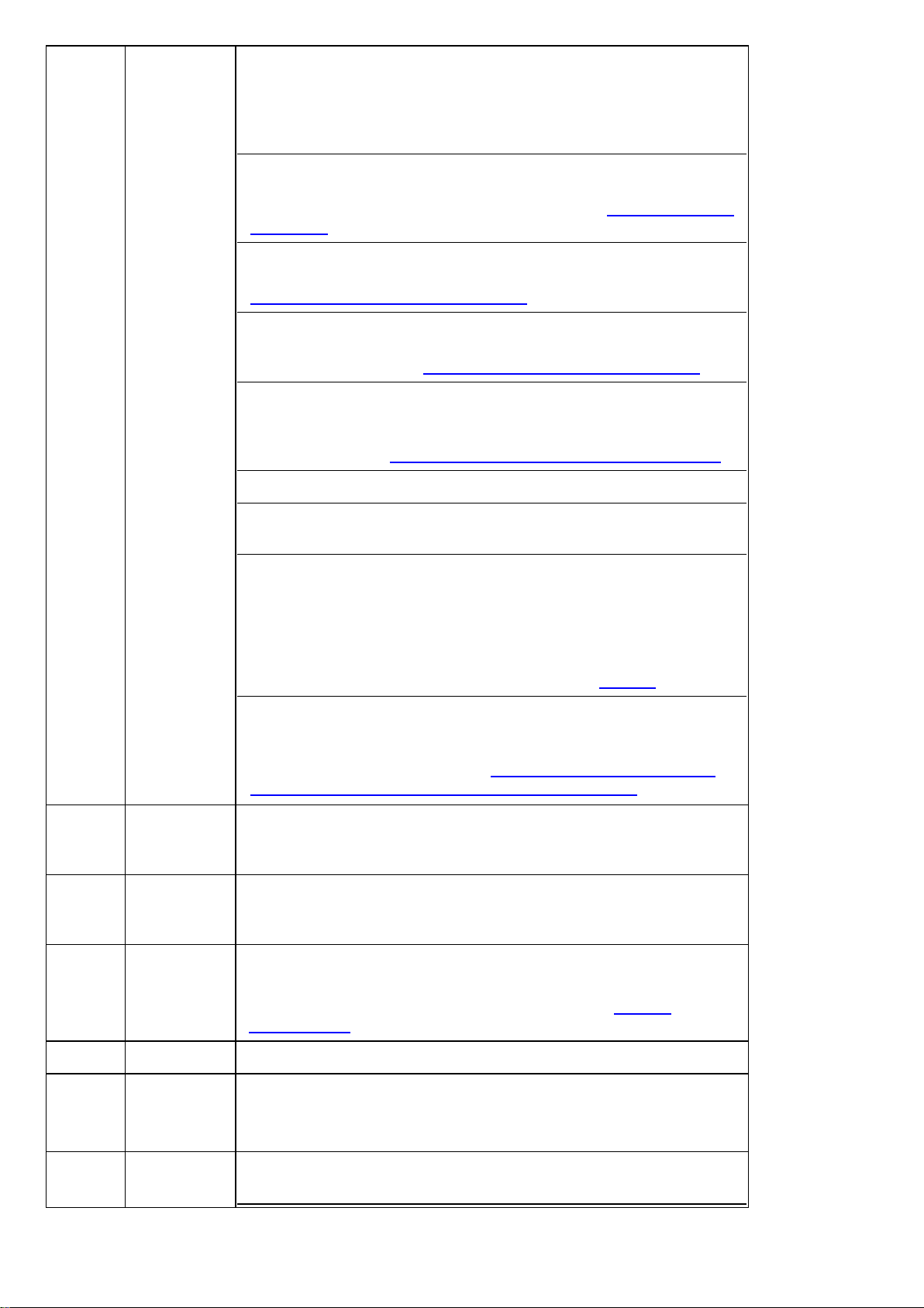
CONFIGURATION:On the CONFIGURATION tab, you can view and
edit device configuration settings, such as the location, Rf-id number,
enrollment method, zone type, chime and subtype. To ensure the
information is up-to-date, click REFRESH. If no configuration is
available, click DOWNLOAD NOW.
VIDEO ON DEMAND
:Appears if the device has video capturing cap-
abilities. To view the video footage of video on demand device, click the
VIDEO ON DEMAND
demand tab
PARENT
.
:Appears if an auxiliary device is wired to a parent device. To
view the parent device, click the
Using the PARENT and CHILDREN tabs
CHILDREN
: Appears if a parent device connects to an auxiliary wired
tab. For more information, see
PARENT
tab. For more information, see
.
device. To view the child device or devices, click the
For more information, see
METEO
: Appears if a device has smart sensing features. To view the
Using the PARENT and CHILDREN tabs
temperature and light data of a smart detector, click the
Using the video on
CHILDREN
tab.
.
METEO
tab. To
find the smart sensing icon, see Smart sensing. For more information on
METEO
the
FIRMWARE
tab, see
: Displays the relevant firmware upgrades that are available.
CONNECTION STATUS
Temperature and light readings on the METEO tab
: Displays the status of the IP and cellular com-
munication channels.
DIAGNOSTIC:
Note: The DIAGNOSTIC tab feature is available for Neo and PSP
panels only.
.
10
11
12
Displays the power statistics of the panel. To refresh this information,
open the panel in the Panel hub, click ACTIONS, then click Read
Diagnostic. For more information, see ACTIONS in Table 30.
TEMPERATURE/LIGHT STATISTIC
: View all the previous temperature and light measurements of a device. This feature is only available for smart devices that can sense temperature and light. To enable
temperature and light recording, see
and light statistics for a group of panels with smart devices
8
Bypass
To disable a device from triggering an alarm, select the
Enabling or disabling temperature
.
Bypass
check
box. The device is not bypassed after the next arm or disarm state
change.
9
Soak
To put a device in a soak state in order to monitor for false alarms, select
Soak
the
check box. A device that is in a soak state does not create an
alarm but a soak event.
Rarely
triggered
Device inactivity causes a remote inspection test to fail. If a device is not
expected to trigger often, select the Rarely Triggered check box.
Note:For more information on remote inspections, see Remote
inspections tab.
REMOVE
Click to remove a device from the panel
RENAME Click to rename a device
Note:For PowerMaster panels the name saves on the server. For Neo
and PSP panels the name saves as a label in the panel.
13 Smart sens-
ing
The smart sensing icon indicates that the device has smart temperature
and light sensing features.
- 63 -
Page 64

If a device has the smart sensing icon, you view temperature and light
readings on the METEO tab. For more information, see
light readings on the METEO tab
14 Camera The camera icon indicates that the device has video capabilities and you
can view the device's video footage in the examination pane.
.
Temperature and
15 Partition
16 Trouble
icons
17 Device type Displays the device type. Examples of device types are contact, LCD
18 Device num-
ber
19 Device zone
type
20 Location
21 Device
RSSI
Related topics
Displays the partition that the device is in
All
indicates that the device is connected to all partitions.
Displays all of the troubles that affect the device. Hover over an icon to
see a description of the trouble.
keypad, and motion outdoor camera.
The device number refers to the zone number for a sensor and the index
number for infrastructural devices, such as a keypad, siren, or repeater.
Displays the device's zone type. Examples of zone types are perimeter,
home delay, interior follow, or fire.
Displays the location of the device.
Note: For PowerMaster panels, the location of zoned devices displays.
For Neo/PSP panels, the label of the device displays.
Displays the Received Signal Strength Indication of wireless devices or
panels that have a cellular connection.
Note:The ? icon indicates that no RSSI measurement exists.
Panel hub
Adding a wireless device to a panel
Bypassing, soak testing, and marking a device as rarely triggered
Editing the configuration of a device
Performing a walk test on all eligible devices
Putting a device in a soak test state
Refreshing the Received Signal Strength Indicator of a panel
Renaming or removing a device
Temperature and light readings on the METEO tab
Using the VIDEO ON DEMAND tab
Viewing device video footage
Viewing all devices with troubles in a panel
Viewing device smart temperature and light readings
Using the PARENT and CHILDREN tabs.
Adding a wireless device to a panel
1. To open a panel in the panel hub, on the Panels page, click the panel name in the PANEL column.
2. Click ADD DEVICE.
3. Enter the enrollment identification number in the Enrollment ID field.
Note:The device ID is on the device's label, written in the following format: ID: XXX-XXXX. The first three digits of the
identification number indicate the device type and the remaining four digits are unique to the device. For more information,
see .
- 64 -
Page 65

4. Enter the desired zone number or the device number.
5. Click ADD.
The device is now pre-enrolled. To complete the enrollment process, refer to the device manual.
Related topics
Devices tab
Panel hub
Refreshing the Received Signal Strength Indicator of a panel
1. To open a panel in the panel hub, on the Panels page, click the panel name in the PANEL column.
2. Click REFRESH RSSI.
Related topics
Devices tab
Panel hub
Viewing all devices with troubles in a panel
1. To open a panel in the panel hub, on the Panels page, click the panel name in the PANEL column.
2. Select the Show devices with troubles check box.
Related topics
Devices tab
Panel hub
Performing a walktest on all eligible devices
1. To open a panel in the panel hub, on the Panels page, click the panel name in the PANEL column.
2. To view the devices that are eligible for a walk test, click WALKTEST.
Note: To return to the DEVICES tab, click DIAGNOSTICS.
3. Click START WALKTEST.
Note: When you click START WALKTEST, the walktest begins and this button changes to STOP WALKTEST. To stop a
walktest click STOP WALKTEST.
Note: The ?icon beside each device indicates the device has not yet passed the walktest. When the device triggers, the ?
icon disappears to indicate that the device passes the test.
Important:
l Neo panel walktests ends if you click STOP WALKTEST or the test times out.
l PowerMaster panel walktests ends if all sensors are activated or the test times out.
Related topics
Devices tab
Panel hub
- 65 -
Page 66

Bypassing, soak testing, and marking a device as rarely triggered
1. To open a panel in the panel hub, on the Panels page, click the panel name in the PANEL column.
2. On the DEVICES tab, select the device to bypass, soak test, or mark as rarely triggered.
3. On the GENERAL tab in the examination pane, select one of the following check boxes to perform the action:
l Bypass
l Soak
l Rarely Triggered
Related topics
Devices tab
Panel hub
Renaming or removing a device
1. To open a panel in the panel hub, on the Panels page, click the panel name in the PANEL column.
2. On the DEVICES tab, click the device to rename or remove.
3. From the GENERAL tab in the examination pane, select one of the following options:
l Click RENAME and enter a new device name in the Name field.
l Click REMOVE.
4. To confirm, click RENAME or REMOVE.
Related topics
Devices tab
Panel hub
Editing the configuration of a device
1. To open a panel in the panel hub, on the Panels page, click the panel name in the PANEL column.
2. On the DEVICES tab, select a device to configure.
3. To view the device configuration settings in the examination pane, click the CONFIGURATION tab. To ensure the configuration is up-to-date, click REFRESH. If there is no configuration information, click DOWNLOAD NOW to download the
most recent configuration data from the device.
4. Edit the required settings. To undo a change, click the undo arrow to the left of the field.
5. To upload the configuration changes to the panel, click UPLOAD. UPLOAD appears above the configuration when you edit
at least one field.
Related topics
Devices tab
Panel hub
- 66 -
Page 67

Using the VIDEO ON DEMAND tab
Note: The following panel setups have video on demand capabilities:
l All PowerMaster panels
l PSP panels with software 1.0, 1.1, and 1.2 that have a FIBRO connection
l PSP panels with software version 1.3 and later that have an ITv2 connection
To view device video on demand in the VIDEO ON DEMAND tab, on the DEVICES tab, select a device with the camera
icon. For more information, see camera in Navigating the Devices tab.
The installer can define during which panel states you can request video on demand, if the video has audio, and many other
settings. For more information on changing the video on demand settings for all devices with video, see CONFIGURATION
tab. For more information on changing the video on demand settings for an individual device with video, see the
CONFIGURATION tab of the device on the DEVICES tab.
Figure: Navigating the VIDEO ON DEMAND tab
Table 32. VIDEO ON DEMAND tab interface elements
Callout Name Description
1 Device type Displays the name of the device
2 Play button Click to play the video and enlarge the screen.
3
VIDEO ON
Click to open the
VIDEO ON DEMAND
DEMAND
4 Forward skip
Click to skip forward one frame
arrow
5 Frames and
Displays the number of frames and the total duration of the video
time
6
7
DOWNLOAD
REQUEST
Click to download the video locally
Click to record new video footage
NEW VIDEO
8 Location and
Displays the time the event occurs and the location of the device
time
9 Back skip
Click to skip backwards one frame
arrow
tab.
Related topics
Devices tab
Panel hub
- 67 -
Page 68

Viewing device video footage
For more information about the VIDEO ON DEMAND tab, see Using the video on demand tab.
1. To open a panel in the panel hub, on the Panels page, click the panel name in the PANEL column.
2. On the DEVICES tab, select a device that contains the video footage to view. A camera icon indicates that a devices has
video capabilities. For more information, see camera in Navigating the Devices tab.
3. On the VIDEO ON DEMAND tab in the examination pane, click the play button in the center of the image to play the last
recorded video.
Note: To view the footage frame by frame, click the left and right arrows on the video.
Related topics
Devices tab
Panel hub
- 68 -
Page 69

Temperature and light readings on the METEO tab
View temperature and light readings from smart detectors on the METEO tab.
To find the METEO tab, in the DEVICES tab, select a smart detector and in the examination pane, click METEO. You can
only open devices with the smart sensing icon in the METEO tab. For more information, see smart sensing in Navigating the
Devices tab.
Figure: Navigating the METEO tab
Table 33. METEO tab interface elements
Callout Name Description
1
2
3
4
5 Detailed
6 Custom stat-
7 Graph line
Brightness
graph
Temperature
graph
METEO
SHOW
graph
istical period
tab
View the brightness readings over a period of time. The x-axis
represents the selected time period and the y-axis represents the
brightness in lumens.
View the temperature readings over a period of time. The x-axis
represents the selected time period and the y-axis represents the
temperature in degrees Celsius.
Click to open the METEO tab
Click to view a more detailed graph.
A more detailed version of the graph. Change the y-axis with a preset
time period or manually change it to a custom time period. For more
information, see Statistical period and Custom statistical period.
Click to enter custom time period dates that change the x-axis of the
graph
Each point on the graph has multiple readings. The gray lines represent
the minimum and maximum readings and the blue line is the average
reading.
8 Statistical
Related topics
period
To change the x-axis of the graph with a preset time, click LAST DAY,
LAST WEEK, LAST MONTH, or ALL.
- 69 -
Page 70

Devices tab
Panel hub
Viewing device smart temperature or light readings
1. To open a panel in the panel hub, on the Panels page, click the panel name in the PANEL column.
2. On the devices tab, select a device that contains the smart temperature or light readings to view. A light bulb icon indicates
that a device has smart temperature or light readings. For more information, see Smart sensing in Navigating the Devices
tab.
3. On the METEO tab in the examination pane, click SHOW to view either the Temperature or Brightness graph in detail.
Note:If the METEO tab does not display, you must enable it. For more information, see Enabling METEO data for a group.
4. Select the time period to view in the examination pane by using one of the following methods:
l To view preset time periods in the examination pane, click LAST DAY, LAST WEEK, LAST MONTH, or ALL.
l To manually enter a time period, click the date field.
Note: The blue line indicates the average light or temperature value and the gray lines indicate the maximum and minimum
values.
Related topics
Devices tab
Panel hub
Enabling METEO data for a group
1. In the navigation pane, from the System list, select Groups.
2. Select the group you want.
3. Click EDIT GROUP.
4. Enable Temperature/light statistic.
- 70 -
Page 71

Using the PARENT and CHILDREN tabs
If a device has other devices connected to it, the connected device appears in the examination pane on the PARENTand
CHILDREN tabs on the DEVICES tab in the panel hub. The PARENT tab appears in the examination pane if an auxiliary
device is wired to a wireless parent device. Similarly, the CHILDREN tab appears if a wireless parent device connects to one
or more auxiliary wired devices.
Figure: Using the PARENT tab
Table 34. PARENT tab interface elements
Callout Name Description
1 Child
device
2 Parent
device
3
PARENT
tab
Click to open in the examination pane.
The parent device of the selected device appears in the examination pane.
Click to open the parent device in the examination pane.
Appears if an auxiliary device is wired to a wireless parent device. To view
the parent device, in the examination pane, click the
PARENT
tab.
- 71 -
Page 72

Figure: Using the CHILDREN tab
Table 35. CHILDREN tab interface elements
Callout Name Description
1 Parent
device
2 Child
devices
3
Related topics
Devices tab
Panel hub
Editing the configuration of a device
Temperature and light readings on the METEO tab
Using the VIDEO ON DEMAND tab
CHILDREN
tab
Click to open in the examination pane.
Any child devices of the selected parent device appear in the examination
pane on the
Click a child device to open it in the examination pane.
Appears if a wireless parent device connects to one or more auxiliary
wired devices. To view the child device or devices, in the examination
pane, click the
CHILDREN
CHILDREN
tab.
tab.
- 72 -
Page 73

Info tab
Navigating the Info tab
View and edit general information about the panel and the customer on the INFO tab.
Leave comments about the panel on the INFO tab. If a panel fault is reassigned to a different user, the comment appears on
the INFO tab. Users can reply to these comments.
Figure: Navigating the INFO tab
Table 36. INFO tab interface elements
Callout Name Description
1
PANEL
INFO
PANEL INFO
The
PANEL ID
To change the panel information, click
2
CUSTOMER
INFO
CUSTOMER INFO
The
name and address.
To change this information, click
log box.
3 Data use
policy
4
SERVICE To perform an action on one or more selected panels, from the SERVICE list, select one of
Personal customer data in the
only.
the following options:
l Mark for service
l Reassign
l Resolve faults
l Suspend faults
section displays basic panel information such as
and version information.
section displays basic panel information such as the customer
EDIT
CUSTOMER INFO
EDIT
to open the
to open the
PANEL NAME
EDIT PANEL
dialog box.
,
EDIT PANEL CUSTOMER INFO
section is used for security purposes
dia-
l Resume faults
For more information on servicing panels, see Servicing panels.
- 73 -
Page 74

5 Reassigned
fault comment
If you reassign a fault, the information logs here with the initials of the person who reassigns
the fault and any message the user leaves.
Note:To reassign a fault, from the SERVICE list, click Reassign.
6 Options Click to open the options dialog box
7
8
REMOVE
Add note
To remove a reassigned fault comment, hover over the comment until three vertical dots
appear. Click the dots and then click
To leave a comment, enter your comment in the
Remove
.
Add note
field and click the post button.
9 Comment Comments that users leave appear in blue on the right hand side. To remove a comment,
hover over the comment until three vertical dots appear. Click the dots and then click
Remove
.
Related topics
Editing basic panel and customer information
Panel hub
Editing basic panel and customer information
To edit basic panel information, or customer information related to a panel, complete the following procedure:
Note:Examples of basic panel information include the following: panel name, panel group, panel account number, and SIM
number. Examples of panel customer information include the following: customer name, email address, home address, and
phone number.
1. To open a panel in the panel hub, on the Panels page, click the panel name in the PANEL column.
2. Click the INFO tab.
3. Perform one of the following options:
l To edit customer information, click EDIT in the CUSTOMER INFO section.
l To edit panel information, click EDIT in the PANEL INFO section. Alternatively, click EDIT on the panel hub. For
more information, see Table 30.
4. Make the required changes.
5. Click SAVE.
Related topics
Info tab
- 74 -
Page 75

State tab
Arm and disarm panels and partitions on the STATE tab.
Note: The Neo panel's STAY arm feature and Visonic panel's HOME arm feature have the same function but different
names. Visonic panels do not have the NIGHT arm feature.
Figure: Navigating the STATE tab
Table 37. STATE tab interface elements
Callout Name Description
1 States
2 Partition
Displays the name of the partition. To change the arm or disarm state for a
partition, click AWAY, NIGHT, STAY, or DISARM.
Note: The All row always appears first in the list. Use the All row to
change the state of all partitions in the panel at once.
Indicates a ready or armed state
Displays when you change to a different panel menu or during
an exit delay period. Examples of panels menus are the user
menu, installer menu, and periodic test menu.
Indicates a not ready state. You cannot arm the panel until
the panel is in a ready state.
To return a panel to a ready state, ensure that all sensors are
physically closed. Doors and windows are examples of
zones that can physically close. If the issue is not physical,
select the Show devices with troubles check box to see all
of the devices with troubles in the examination pane and
select the BYPASS check box to bypass devices with
troubles.
3 Arming
options
The STAY/HOME and AWAY buttons have arming sub-options. To view
the sub-options list, click the drop-down arrow.
You can select NO ENTRY and NO EXIT from the STAY list, and NO
ENTRY from the AWAY list. For the system to alarm when someone
- 75 -
Page 76

enters the perimeter, select NO ENTRY. For the system to alarm when
someone exits the perimeter, select NO EXIT.
4 Arm state The active state is blue.
5 Selected
6 Troubles
7 Device par-
8 Trouble
9 Associated
10
Related topics
Devices tab
Click the row of a partition to view it in the examination pane.
partition
Note:Partitions appear on the STATE tab if they are enabled in the panel.
To enable panel partitions, enable and configure Partition set on the
CONFIGURATION tab.
Select to view all of the devices with troubles in the partition
check box
Displays the name of the selected partition that features in the examination
tition
pane
Displays the types of troubles that affect the device. Hover over an icon to
icons
see a description of the trouble.
A list of all of the partitions that associate with the device
partitions
BYPASS Select to bypass a device. If a panel is in a not ready state, bypass any
troubled devices to return it to a ready state. The system bypasses the
device until the next arm or disarm state change. For more information
about states, see States.
Bypassing, soak testing, and marking a device as rarely triggered
Viewing all devices with troubles in a panel
Panel hub
- 76 -
Page 77

Configuration tab
Navigating the Configuration tab
Configure an individual panel and its zones, outputs, communication, and user settings on the CONFIGURATION tab. You
can also save a panel configuration as a basic configuration that you can push to multiple panels.
To view a configuration on the Configuration tab, select a configuration from the current and previous panel configurations
list. For more information, see Current and previous panel configurations list.
You can only edit a configuration if it is the current configuration. For information on changing the configuration settings, see
Editing the configuration settings of an individual panel.
You can only download a panel configuration if the panel is connected to the server. The blue bulb indicates if the panel is
connected. For more information, see Online status in Table 30.
For information on pushing a basic configuration to one or more panels, see Pushing a basic configuration to one or more
panels.
Figure: Navigating the Configuration tab
Table 38. CONFIGURATION tab interface elements
Callout Name Description
1 Configuration
date
2 Hidden char-
acters
3
4
5
REFRESH
SAVE AS
BACKUP
MAKE
BASIC
Each configuration download is distinguished by the date of download.
Secure information such as pass codes are hidden.
Refresh the page with the latest data from the panel.
Save configuration as a backup configuration.
Click to make the configuration a basic configuration that you can push to other panels.
Find the basic configurations on the Basic configurations page in the System drop-down
list. For more information, see Basic configurations page. For more information about
making a basic configuration, see Creating a basic configuration from an existing panel
configuration.
- 77 -
Page 78

6
Compare
Compare current configuration with the backup configuration.
with backup
7
8
Show only
changed
Quick
Click to show only the configuration settings that you changed. You can only edit a configuration if it is the current configuration. For more information, see
panel configurations list
.
Filter the configuration to return only values that contain the search term.
search
9
TABLE OF
CONTENTS
Use the table of contents to navigate the configuration quickly. The table of contents is categorized and expandable.
Related topics
Panel hub
Devices tab
Creating a basic configuration from an existing panel configuration
Current and previous panel configurations list
Editing the configuration settings of an individual panel
Synchronizing a the configuration of an individual panel
Current and previous
- 78 -
Page 79
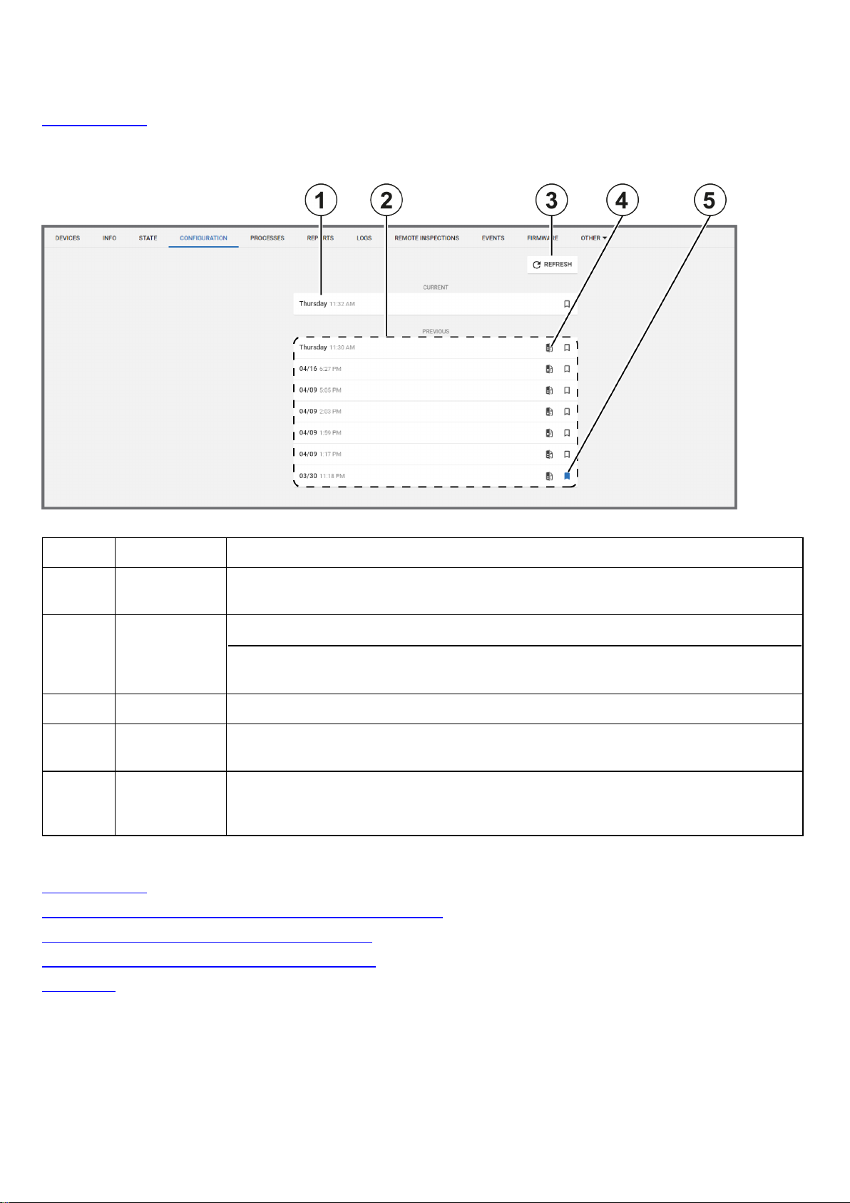
Current and previous panel configurations list
View and edit up to eight panel configurations for an individual panel in the configurations list. The configurations are ordered
by the date of download. Select a configuration to view it in the CONFIGURATION tab. For more information, see
Configuration tab.
If a panel is newly registered on the server, click DOWNLOAD NOW to download the panel configuration to the server.
Figure: Navigating the panel configurations list
Table 39. Configuration list interface elements
Callout Name Description
1 Current con-
figuration
2 Previous con-
figurations
3
4 Compare con-
5 Bookmark
Related topics
Configuration tab
Creating a basic configuration from an existing panel configuration
Editing the configuration settings of an individual panel
REFRESH
figuration
You can edit the current configuration only. Click to view or edit.
View seven previous configurations in the
If you download a new configuration, it overwrites the oldest configuration in the
PREVIOUS
Click to refresh the configurations list.
Click to compare the configuration with the current configuration.
To ensure a configuration from the PREVIOUS list is not overwritten by new
configurations, click the bookmark icon. You can only save seven previous configurations
at a time from the PREVIOUS list.
list. To ensure a configuration is not overwritten, click the bookmark icon.
PREVIOUS
list.
Synchronizing a the configuration of an individual panel
Devices tab
Creating a basic configuration from an existing panel configuration
1. To open a panel in the panel hub, on the Panels page, click the panel name in the PANEL column.
2. From the CONFIGURATION tab, click REFRESH to synchronize the panel and the server.
Important: Click REFRESH in the CONFIGURATION tab, not REFRESH above the panel hub tabs.
- 79 -
Page 80

3. From the CURRENT list, select the current panel configuration.
4. Click MAKE BASIC.
5. Select the check boxes of the settings to include in the basic configuration.
6. Click CREATE.
7. Enter a unique name in the Basic configuration name field.
8. Click SAVE.
Related topics
Configuration tab
Creating a basic configuration from an existing panel configuration
Current and previous panel configurations list
Editing the configuration settings of an individual panel
Synchronizing the configuration of an individual panel
Devices tab
Synchronizing the configuration of an individual panel
1. To open a panel in the panel hub, on the Panels page, click the panel name in the PANEL column.
2. From the CONFIGURATION tab, click REFRESH.
Related topics
Configuration tab
Creating a basic configuration from an existing panel configuration
Current and previous panel configurations list
Editing the configuration settings of an individual panel
Devices tab
Editing the configuration settings of an individual panel
1. To open a panel in the panel hub, on the Panels page, click the panel name in the PANEL column.
2. To synchronize the panel and the server, from the CONFIGURATION tab, click REFRESH.
Note: If there is no refresh option, select DOWNLOAD NOW.
3. From the CURRENT list, select the current panel configuration.
4. Make the required changes and select the Show only changed check box to review your changes.
5. Click UPLOAD.
Related topics
Configuration tab
Creating a basic configuration from an existing panel configuration
Current and previous panel configurations list
Synchronizing the configuration of an individual panel
Devices tab
- 80 -
Page 81

Locations tab
Provide custom location names to zones for ease of reference.
Note: The LOCATIONS tab only appears in the panel hub for PowerMaster panels.
Figure: Locations tab
Table 40. LOCATIONS tab interface options
Callout Name Description
1
2
Related topics
Devices tab
Panel hub
Show only
editable locations
SAVE
LOCATIONS
To view only locations that you can rename, select the
check box.
To rename a location, type a new name in at least one field and click
Enter a maximum of 15 characters in any field. Type only the following characters only in
the location fields:A-Z,a-z,0-9,!,@,#,%,^,&,_,+,=,-,',",:,
Show only editable locations
SAVE LOCATIONS
/
.
- 81 -
Page 82

Processes tab
View a list of all processes for the selected panel on the PROCESSES tab. Each row represents a single process. Each
process displays with a start time, description, current status, process initiator name, and duration.
Click X to cancel a process.
To view a list of all recent processes for all of the panels that are enrolled in the server, in the navigation pane, from the
System list, select Processes. For more information about the Processes page, see Processes page.
Related topics
Devices tab
Processes page
Panel hub
- 82 -
Page 83
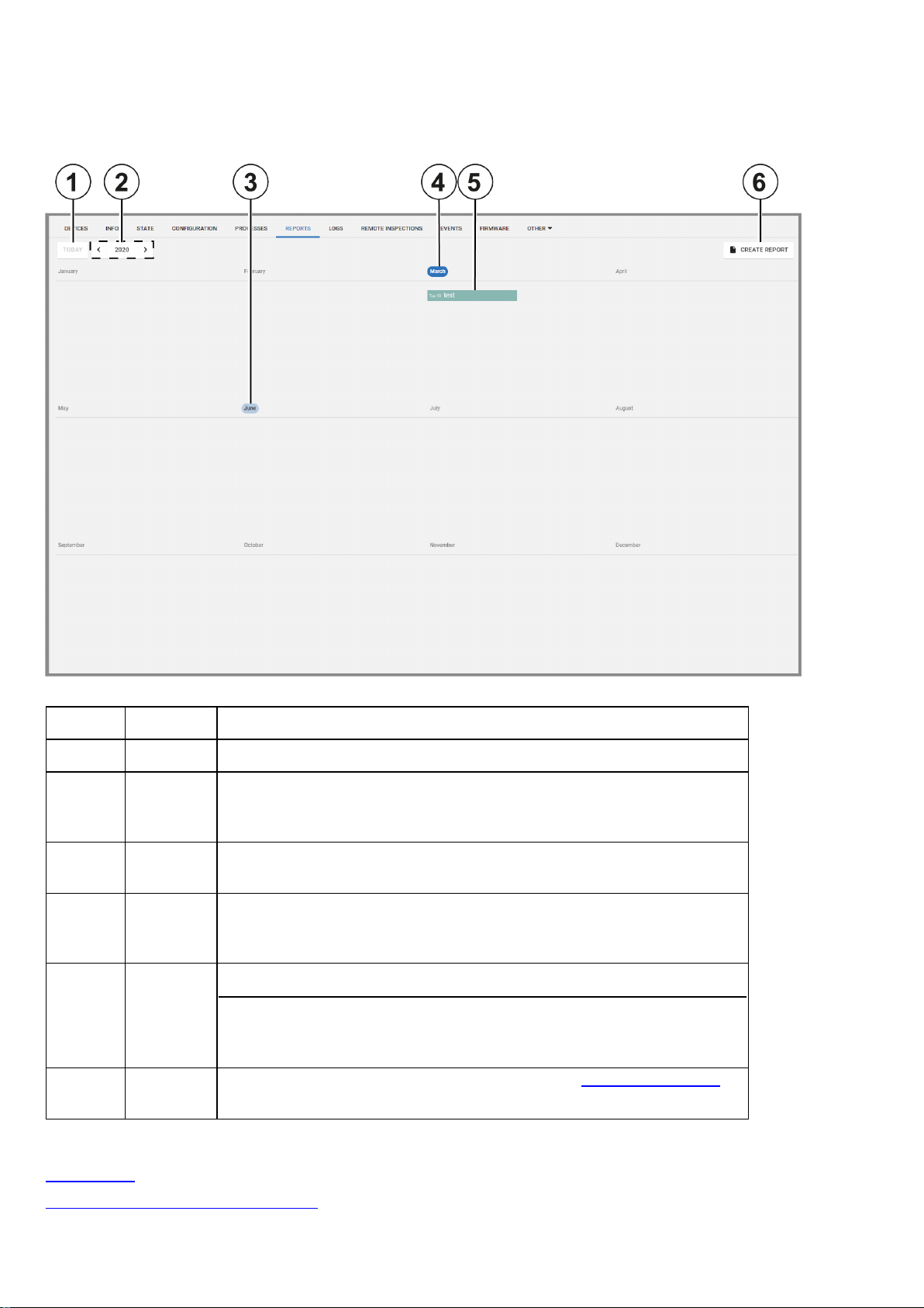
Reports tab
View reports that have occurred or are scheduled to occur for an individual panel on the REPORTS tab. The tab displays this
information on a calendar.
Figure: Navigating the Reports tab
Table 41. REPORTS tab interface elements
Callout Name Description
1 Today Click
2 Month
and year
selector
3 Select
month
4 Current
date or
month
5 Report
6
Related topics
CREATE
REPORT
Click to create a new report. For more information, see
TODAY
The calendar displays one month or one year at a time. To change the month
or year, click the arrows to the left of the month name. To change from the
month view to the year view, click the button between the arrow selectors.
Click a month to open the calendar month in the viewer.
A blue circle indicates the current day or month.
All reports appear in the calendar and each report is a different color.
Select a report to display the file download options. Click
download the report in the chosen format. PDF is a more readable file type
than CSV.
to return to the current month.
CSVorPDF
Creating new reports
to
.
Reports page
Creating a new report on the Panels page
- 83 -
Page 84

Creating a new report on the Reports page
Devices tab
Panel hub
- 84 -
Page 85

Logs tab
Navigating the Logs tab
View log files on the LOGS tab. Log files record all events that occur in the panel.
Figure: Navigating the LOGS tab
Table 42. LOGS tab interface elements
Callout Name Description
1 Event number Each event in the panel has a number that identifies the event type.
2 Event time Displays the time that the server receives the event notification from the panel
3 Event descrip-
A textual description of the event
tion
4 Date Events are grouped by the day they occur.
5 Event source
ID
Displays the ID of the source of the event.
l The source ID for a sensor is its zone number.
l The source ID for an arm or disarm state change is the user number of the user
who changed the arm state.
l The source ID for an action that the panel performs is the panel name.
Note:The source ID is followed by the number of the partition that the event occurs in.
6
7
REFRESH
DOWNLOAD
Click to download the most up-to-date log file on the
Download a CSV file of the events log
LOGS
tab
CSV
8 Standard and
Click STANDARD LOG or LEGACY LOG to display the log list on the LOGS tab.
legacy logs
Users can view and erase the standard log.
Security operators and systems use the legacy log. The legacy log appears for
- 85 -
Page 86

PowerMaster panels only.
Related topics
Downloading a panel log file in the Panels hub
Devices tab
Panel hub
Downloading a panel log file in the panels hub
1. To open a panel in the panels hub, click the panel name in the PANEL column of the Panels page.
2. From the LOGS tab, click DOWNLOAD CSV.
The file downloads in the browser.
Related topics
Logs tab
Devices tab
Panel hub
- 86 -
Page 87
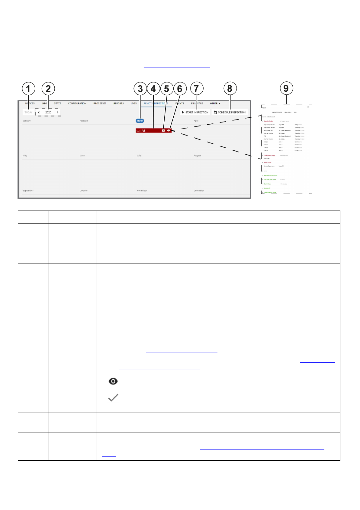
Remote inspections tab
Navigating the Remote inspections tab
Manage the remote inspections for a single panel on the REMOTE INSPECTIONS tab in the panel hub.
For more information on remote inspections, see Remote inspections page.
Figure: Navigating the REMOTE INSPECTIONS tab
Table 43. REMOTE INSPECTIONS tab interface elements
Callout Name Description
1
2 Year and
TODAY
month filter
Click to return to today's date.
Use the arrows to navigate the remote inspections by year or month on the calendar interface. When you are in the monthly view, click the button between the arrows to return to
the annual view.
3 Month Select the month to open it in the viewer. The current month is highlighted.
4 Inspection
All scheduled remote inspections appear in the calendar. The reports colors indicate the
following test statuses:
l Red: the test failed
l Green:the test succeeded
5 Send email
Click the email icon to send the results of the remote inspection to a predefined email address.
Note:
l Define the email address when you add a panel on the Panels page. For more inform-
ation, see Adding a panel to the server.
l Change the email address on the INFO tab. For more information, see Editing basic
panel and customer information.
6 Viewing
status
Click to mark the remote inspection as viewed.
The remote inspection is viewed. Only mark a remote inspection as viewed if
your investigation is complete.
7
START
Click to initiate the selected remote inspection
INSPECTION
8
SCHEDULE
INSPECTION
Click to schedule the selected remote inspection to occur at a specific date and rate of
recurrence. For more information, see
panel
.
Scheduling a remote inspection for an individual
- 87 -
Page 88

9 Examination
pane
Related topics
Remote inspection tests
Remote inspection page
Devices tab
Panel hub
To examine the results of a remote inspection in the examination pane, click the remote
inspections row. Select a section title to expand the test results. For more information on
each test, see
Remote inspection tests
.
Scheduling a remote inspection for an individual panel
Note:To schedule a remote inspection for a batch of panels, see Scheduling one or more remote inspections for a batch of
panels.
1. To open a panel in the panel hub, on the Panels page, click the panel name in the PANEL column.
2. On the REMOTE INSPECTIONS tab, click SCHEDULE INSPECTION.
3. In the dialog box, select Enabled.
4. Enter the required date in the Next Inspection field.
5. In the Choose repetition field, select how often you want the test to occur. You can select Once, 1 Month, 3 Months, 6
Months, or 9 Months.
6. Click SAVE.
Related topics
Remote inspections tab
Scheduling one or more remote inspections for a batch of panels
Remote inspection tests
Remote inspection page
Devices tab
Panel hub
- 88 -
Page 89

Events tab
View events related to a single panel on the EVENTS tab.
Figure: Navigating the EVENTS tab
Table 44. EVENTS tab interface elements
Callout Name Description
1 Event time The time the event occurs
2 Video con-
tent
3 Event
description
4 Selected
event
5
LOAD
OLDER
6 Device
The camera icon indicates that the event has video footage that you can
view on the
EVENT VIDEO
A description of the alarm type. For more information, see Event severity in
Table 48
.
Select an event row to view information about the related device in the
examination pane.
Click to load older events. By default, only 10 events display on the
EVENTS
tab.
Displays the device number and its partition
number
and partition
7 Viewing
status
Click the icon to mark the event as viewed.
The event is viewed. Only mark an event as viewed if your
investigation is complete.
8
EVENT
VIDEO
tab
The EVENT VIDEO tab appears if the selected device has a camera.
Select the EVENT VIDEO tab to view the video footage related to the
event.
tab.
9 Video foot-
age
If an event has video, view the video footage here.
l Click play to view video footage.
l Click the arrows to view the footage frame by frame.
l Click DOWNLOAD to download the video file locally.
l For more information about viewing event video footage, see View-
ing event video footage in the events tab.
- 89 -
Page 90

10
LIVE
VIDEO
tab
Click the LIVE VIDEO tab to view live video footage from the source
device. The live video stream lasts five seconds.
Note:The LIVE VIDEO tab appears for Visonic panels only. You can
enable or disable live video on demand capabilities during specific states
only, such as an armed state. Define the video demand settings in the
Video on demand field on the panel CONFIGURATION tab.
11 Device
General information about the source of the event, such as a device.
information
Related topics
Events page
Viewing event video footage in the events tab
Devices tab
Panel hub
- 90 -
Page 91

Firmware tab
Navigating the Firmware tab
Upgrade an individual panel's software and its connected devices on the FIRMWARE tab.
For Visonic panels, you can only upgrade panels and the power link. For Neo panels, you can upgrade the panel, the
communicator, and any wired devices and modules. For more information about upgrading panels, devices, and modules, see
Firmware page.
Figure: Navigating the FIRMWARE tab
Table 45. FIRMWARE tab interface elements
Callout Name Description
1
2
3
4
5
6
Related topics
Firmware page
Upgrading the firmware related to an individual panel in the Panels hub
Devices tab
Panel hub
APPLIANCE
CURRENT
VERSION
Do not
upgrade
APPLY
PACKAGE
APPLY
PACKAGE
drop-down
UPGRADE
Displays the appliance
Displays the current software version of the appliance
By default, no package is selected from the
Find packages that are available for upgrade in the APPLY PACKAGE column.
Note: T.3 tech support loads upgrade packages to the repository server.
Select an upgrade package from the
Click upgrade to upgrade an appliance to the selected package. For more information, see
Upgrading the firmware related to an individual panel in the Panels hub
APPLY PACKAGE
APPLY PACKAGE
list.
list.
.
Upgrading the firmware of an individual panel in the panel hub
1. To open a panel in the panel hub, on the Panels page, select the panel name in the PANEL column.
2. On the FIRMWARE tab, select the device to upgrade.
3. From the APPLY PACKAGE list, select an upgrade package.
4. Click UPGRADE.
Related topics
Firmware tab
Firmware page
Devices tab
- 91 -
Page 92

Panel hub
- 92 -
Page 93
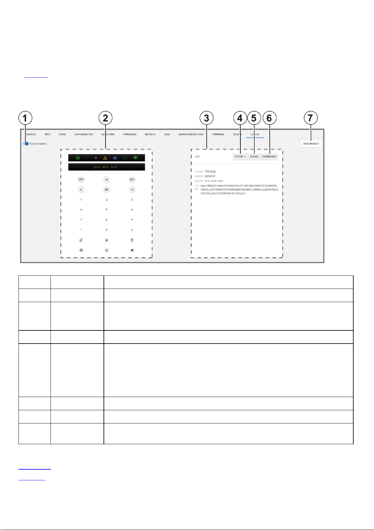
Keypad tab
Use a virtual keypad interface on the KEYPAD tab. To open a virtual keypad on the KEYPAD tab, click CONNECT NOW to
connect to the physical keypad.
Important:Click DISCONNECT after you use the virtual keypad to disconnect from the physical keypad. If you do not
disconnect, a communication backlog occurs and no other virtual keypad can connect. For more information, see Disconnect
in Table 46.
Note: You can use the virtual and physical keypads simultaneously with Visonic panels. If you activate a Neo or PSP virtual
keypad, the physical keypad deactivates.
Figure: Navigating the KEYPAD tab
Table 46. KEYPAD tab interface elements
Callout Name Description
1
Sound
toggle Turn on
Sound enabled
to enable the sound of keypad notifications.
2 Virtual keypad The virtual keypad mirrors the keypad buttons and the live LED and LCD display of the
physical keypad. The LED display features the power status, trouble status, WAN, and
WiFi connectivity icons.
3 Log The log file records all messages between the keypad and the panel.
4
FILTER To show only a specific category of message, from the FILTER list, select any of the
following options:
l Key: Display messages related to key presses only
l Leds: Display messages related to LED status only
l Text: Display messages related to LED text only
5
6
7
CLEAN
DOWNLOAD
DISCONNECT
Click to erase the log
Click to download the log locally
Click when you finish using the virtual keypad. Some physical keypads cannot function
when the virtual keypad is connected.
Related topics
Devices tab
Panel hub
- 93 -
Page 94

Remote Inspection page
Navigating the Remote Inspection page
A remote inspection is a series of nine tests that check a panel remotely for any faults that affect the system and its
functionality. If at least one of the nine tests fail, the inspection fails. For more information about each inspection test, see
Remote inspection tests.
Tests can be performed once or periodically. Finished remote inspections appear at the top of the page and uninitiated tests
appear at the bottom of the page.
Filter your search of the Remote Inspection page by selecting one or more filter values from the Search list. From the
Search list, select a filter value from one or more of the following keys: NAME, ACCOUNT, PANEL ID, GROUP, LAST
RRI, NEXT RRI, EMAIL SENT, and REVIEWED. For more information, see Using the search filter.
Figure: Navigating the Remote Inspection page
Table 47. Remote inspection page interface elements
Callout Name Description
1 Check box
2 Failed test Red text indicates that the test is complete and that there was at least
3 Successful
test
4 Selected
test
5
6
MARK AS
VIEWED
SCHEDULE Click to schedule one or more reports. SCHEDULE appears when you
Select one or more check boxes to perform an action.
Select a check box to enable
RUN
.
one failure.
Green text indicates that the test is complete and that no failure is found.
Click a completed test to view it in the examination pane.
Click to mark one or more remote inspections as viewed. MARK AS
VIEWED appears when you select a check box.
select a check box.
MARK AS VIEWED,SCHEDULE
, and
- 94 -
Page 95

7
RUN Click to run one or more reports immediately. RUN appears when you
select a check box.
8 Email icon
Email the results of the completed remote inspection to a user. This has
the same function as SEND EMAIL.
Note: For PowerMaster panels, the email address is defined in the
private panel report. For Neo and PSP panels, the email address is
defined on the INFO tab. For more information on the INFO tab, see Info
tab.
9 Mark as
viewed icon
Click to mark the completed remote inspection as viewed. This has the
same function as MARK AS VIEWED.
If a remote inspection is viewed, hover over the icon to see who viewed
the report and when.
10 Schedule
icon
Click the schedule icon to schedule a remote inspection or stop a scheduled remote inspection. This has the same function as
SCHEDULE
11 Run icon Click to run a report immediately. This has the same function as
12 Progress
Displays the completion percentage of a report that is in progress
tracker
13 Result color
When you view a report in the examination pane, the report title color
indicates success or failure.
l If the report title is green, the test is successful
l If the report title is red, the test is unsuccessful.
RUN
.
.
14
MARK
REVIEWED
15
SEND
EMAIL
16
17
18
SETTINGS
RUN
UPLOAD
SCHEDULE
19 Examination
pane
20 Next report
l If the report title is gray, the test did not complete due to lack of
information.
Note: To see a description of each test, see Remote inspection tests.
Click to mark a completed remote inspection as reviewed. This has the
same function as MARK AS VIEWED.
Note: If the report is already reviewed, this text is gray.
Click to email the results of a completed remote inspection to a user that
is defined in the private report in the panel. This has the same function as
the email icon.
Click to configure the general remote inspection settings. For more
information, see
Remote inspection values
.
Click to run a report again immediately. This has the same function as
Run icon and
RUN
.
Click to create a new remote inspection schedule. For more information,
Creating a remote inspection for a batch of panels
see
.
Click a report to review the results in the examination pane.
Note: To see a description of each test, see Remote inspection tests.
Click the arrow to review the next report in the test results window.
Note: Click the arrow on the opposite side of the test results window to
review the previous report.
Related topics
Remote inspection tests
Remote inspection values
Creating a remote inspection for a batch of panels
- 95 -
Page 96

Canceling a remote inspection
Running a remote inspection manually
Scheduling one or more remote inspections for a batch of panels
Remote inspection tests
When you view a completed remote inspection in the examination pane, see to the following definitions:
Note: For more information about the examination pane, see Examination pane in Table 47.
Active faults
The Active Faults test is an inspection that checks the panel for faults that currently affect the operation of the panel.
Check clock
The Check Clock test is an inspection that checks if the time difference between the panel clock and the server clock is
greater than the value set in Remote inspection values.
GPRS
The GPRS test is an inspection that checks for a GPRS heartbeat. The GPRS test passes in one of the following cases:
l The GPRS module does not exist. The test title displays in the color gray.
l The GPRS module exists but the keepalive messages are disabled. To disable or enable keepalive messages, see
the GPRS Keep Alive Enabled toggle in Group parameters.
l The GPRS module exists and keepalive messages arrive on time.
Reported faults
The Reported Faults test is an inspection that checks the panel log file for faults. The test fails if a fault is found.
To define the number of recent events that the test inspects for faults, see Check for reported faults in last in Remote
inspection values.
Total system usage
The Total System Usage test is an inspection that checks the panel for any arm or disarm logs.
l If there is at least one arm or disarm log, the test passes.
l Define how many reports from the panel that the test inspects in Remote inspection values.
Bypassed/In-test zones
The Bypassed/In-test Zones test is an inspection that checks the panel for any log of a bypassed zone. If the test finds that
a zone is bypassed, the test fails.
Frequently used zones
The Frequently used zones test is an inspection that checks if zones have been activated in the time defined in the Check
frequently used zones not used over value in Remote inspection values. If the time of inactivity is greater than the defined
time, the test fails.
Note: The test bypasses zones that are defined as rarely triggered. To mark a zone as rarely triggered, see Bypassing, soak
testing, and marking a device as rarely triggered.
Broadband
The Broadband test is an inspection that checks for the presence of a broadband heartbeat.
l If the panel is not connected by broadband or there is no broadband module, the test title displays in the color gray.
l If there is a heartbeat, the test passes. If there is no heartbeat, the test fails.
Failed soak test zones
The Failed Soak test Zones test is an inspection that checks for soak test zones that cause an alarm. If there are no
sensors in soak test mode or no alarms from sensors in soak test mode, the test passes.
Note:To put a device in a soak test state, see Putting a device in a soak test state.
- 96 -
Page 97

Remote inspection values
To change the remote inspection settings, on the Remote Inspections page, click SETTINGS and set your testing
preferences. The definition list below defines each setting:
Check for reported faults in last
Set the number of recent events that the test inspects for faults in the panel log file.
l The test fails if a fault is found.
l Select either 10, 20, or 30 events to inspect.
Total system states in last
Set the number of reports that the test inspects for arm or disarm logs.
l The test fails if a system state change is not found in the panel log file.
l Select either 40, 60, or 120 reports to inspect.
Check frequently used zones not used over
Set the period of time the test inspects frequently used zones for an activation log. By default, all zones are defined as
frequently used.
If a zone is rarely used, mark it as rarely triggered. To mark a device as rarely triggered on the DEVICES tab, see Bypassing,
soak testing, and marking a device as rarely triggered.
Note: A zone is a sensor.
Treat adjusted date/time as failure if adjustment is over
Set the maximum allowed time difference between the panel and server clocks. If the time difference is greater that the value,
the test fails.
Figure: REMOTE INSPECTION VALUES dialog box
Related topics
Navigating the Remote Inspection page
Creating a remote inspection for a batch of panels
Note:To create a remote inspection for a single panel, see Scheduling a remote inspection for an individual panel.
1. Open a new spreadsheet using your chosen application.
2. In the first row, type the panel name in column A, type the inspection date in column B, and type the number of months
between each repetition in column C. For more information, see Figure.
Note:
l Enter the date in the following format: YYYY-MM-DD.
l The recognized inspection repetition values for column C are: 0, 1,3, 6, 9. To perform the test once only, enter a
value of 0.
3. Optional: To add an additional panel, type the relevant information in the row below the first entry and follow the same
column format. You can add multiple panels.
4. To save the file in a comma delimited format, save the spreadsheet as a CSV file.
- 97 -
Page 98

5. From the navigation pane in the PowerManage web application, click Remote Inspection.
6. Click UPLOAD SCHEDULE.
7. Click CHOOSE FILE and select the CSV file.
The remote inspection now appears on the Reports page.
Figure: Spreadsheet example
Related topics
Navigating the Remote Inspection page
Scheduling a remote inspection for an individual panel
Scheduling one or more remote inspections for a batch of panels
Note:To schedule a remote inspection for a single panel, see Scheduling a remote inspection for an individual panel.
1. In the navigation pane, click Remote Inspection.
2. Select the check box of the remote inspection to schedule.
3. Click SCHEDULE to open a dialog box.
4. In the Next Inspection field, enter a date manually or select a date in the calendar.
5. From the Choose repetition list, select how often you want the remote inspection to occur. You can select Once, 1
month, 3 months, 6 months, or 9 months.
6. Click SAVE.
Related topics
Navigating the Remote Inspection page
Scheduling a remote inspection for an individual panel
- 98 -
Page 99

Canceling a remote inspection
1. In the navigation pane, click Remote Inspection.
2. Select the check box of the remote inspection you want to cancel.
Note: You can only cancel a report that is scheduled to run.
3. Click CANCEL.
4. In the dialog box, click CANCEL.
Related topics
Navigating the Remote Inspection page
Running a remote inspection manually
1. In the navigation pane, click Remote Inspection.
2. Select the check box of one or more remote inspections to run manually.
3. Click RUN.
4. Click BEGIN NOW.
Related topics
Navigating the Remote Inspection page
- 99 -
Page 100

Events page
Navigating the Events page
View a list of all panel events on the Events page.
Filter the Users page to return a match of specified criteria that you set in the search bar. Filter your search with one, or a
combination of the following criteria:SEVERITY, PANEL ID, PANEL NAME, ACCOUNT, HAS VIDEO, DATE and TYPE.
For more information about using the search filter, see Using the search filter.
Figure: Navigating the Events page
Table 48. Events page interface elements
Callout Name Description
1 Events
since last
logon
2 Check box
3
4 Panel name Click the panel name to open it in the panel hub on the
5 Event sever-
MARK AS
VIEWED
ity
Displays the number of unresolved events since the user last logged on.
To enable the notification, from the user icon list, select
Enable alarm supervision
on
see User icon in .
Select the check box of one or more events to enable MARK AS
VIEWED.
Click MARK AS VIEWED to mark multiple events as viewed. This
button has the same function as the Viewed icon, but it can be performed
on more than one event.
Important: Only mark an event as viewed if your investigation is
complete.
more information, see
The offline notification icon appears if the PowerManage
server does not receive a keepalive message from the
panel.
Note: Define the delay between the panel's last keepalive
message and the offline notification in the Groups page. For
more information, see Group parameters.
Panel hub
. For more information on the user icon,
.
Settings
DEVICES
and turn
tab. For
- 100 -
 Loading...