

Page 1
Features
•• Internal Square Root
Extractor
•• High Degree of Accuracy
•• Pneumatic Feedback
•• Movement Release Knob
to Maintain Calibration
Setting During Shipping
•• Minimal Field Calibration
Required
Pneumatic Control Manual 717.1
Pressure Section
Product Bulletin P-5219
Issue Date 1088
P-5219
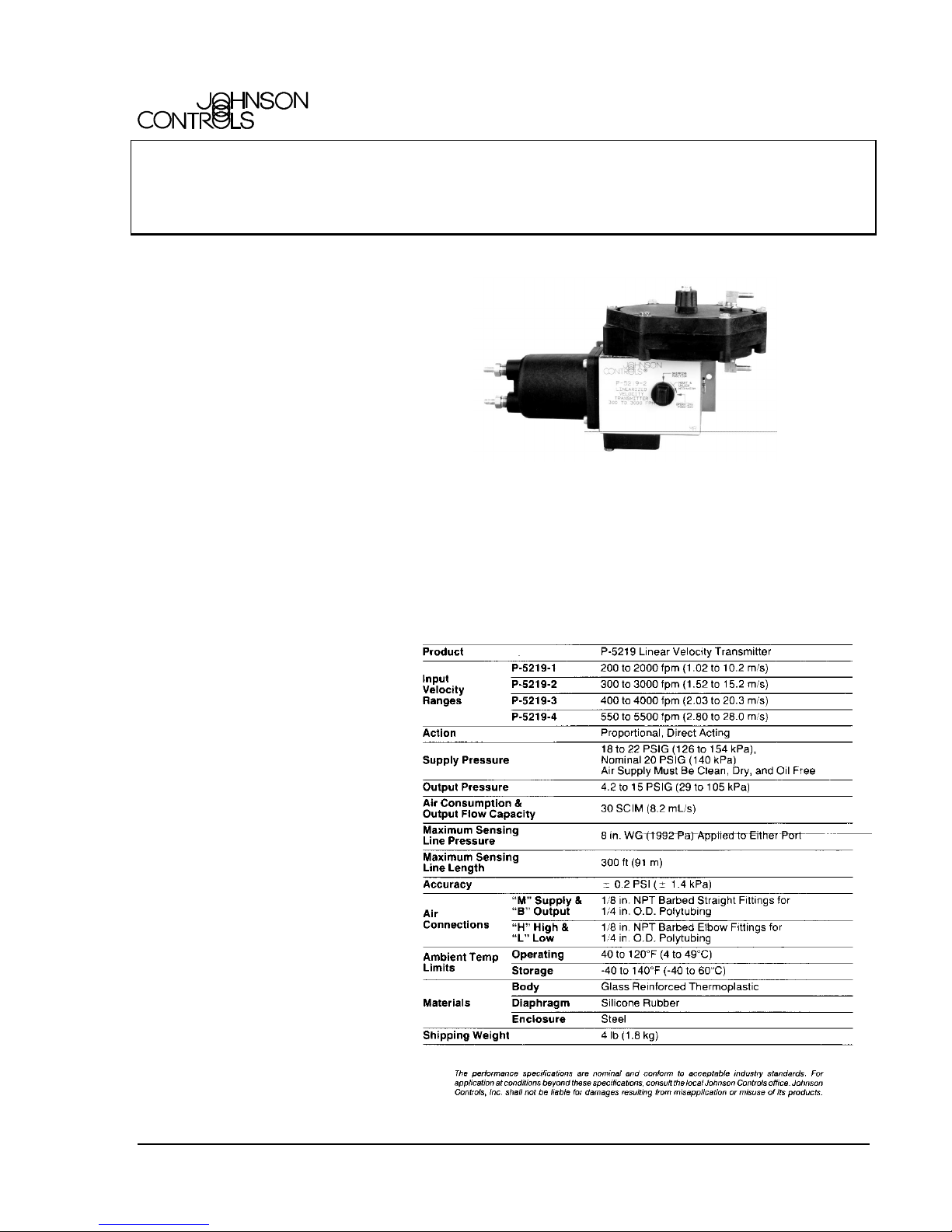
Linear Velocity Transmitter
The P-5219 Linear Velocity
Transmitter is designed to
produce a linear 4.2 to 15 PSIG
(29 to 105 kPa) output signal
with respect to the calibrated
input velocity range of the
instrument. Applications for this
transmitter include constant
volume control and constant
volume differential control for
return fans on VAV systems.
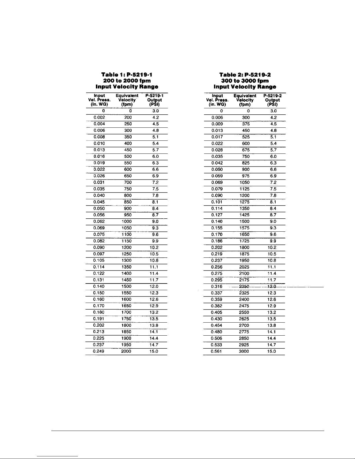
Operation
The P-5219 employs a highly
sensitive differential pressure
diaphragm to compare static
and total pressure from a duct
mounted pitot tube or air flow
measuring station. The
resultant velocity pressure
signal is converted to a linear
velocity signal by an internal
square root extractor, which
eliminates the need for a
separate device.
Installation
Fig. 1: P-5219
Linear Velocity Transmitter
Specifications
The P-5219 should be located on
a vibration-free surface with the
diaphragm oriented within
5 angular degrees of a horizontal
plane. To install and calibrate
the P-5219, refer to Fig. 2 and
proceed as follows:
1. Secure the mounting
bracket to the surface using
© 1988 Johnson Controls, Inc. 1
Code No. LIT-7171230
Page 2
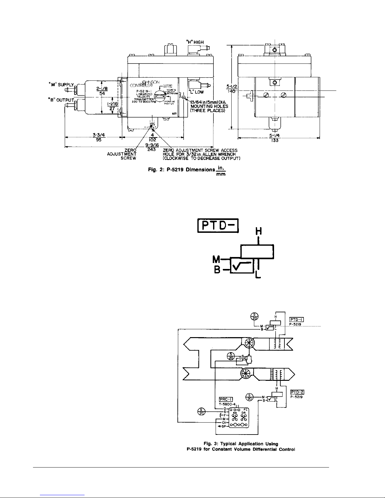
the three #8 sheet metal
screws provided, making
sure that the side of the
bracket marked “TOP” is
upward.
2. Push the mounting release
knob in and turn it to the
“MOUNT AND UNLOCK”
position.
3. Align the pins on the bottom
front of the mounting
bracket with the slots in the
body of the P-5219. While
holding the P-5219 firmly
against the bracket, push
the mounting release knob
in and turn it to the
“OPERATING” position.
4. With the “H” and “L”
sensing lines disconnected,
furnish a 20 PSIG
(140 kPa) supply to the unit
and turn the zero
adjustment screw (using a
3/32 in. Allen head wrench)
to provide a 3 PSIG
(21 kPa) output signal.
No further field calibration
is required.
Application and Drawing
Identification
Repair Information
Field repairs must not be made.
For a replacement P-5219,
contact the nearest Johnson
Controls branch office.
2 P-5219 Product Bulletin
Page 3
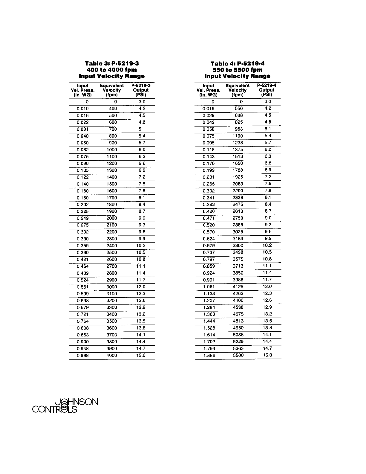
-- Velocity Data Continued on Next Page --
P-5219 Product Bulletin 3
Page 4
Controls Group
507 E. Michigan Street
P.O. Box 423 Printed in U.S.A.
Milwaukee, WI 53202
4 P-5219 Product Bulletin
 Loading...