

Page 1
System 350 Product Guide 930
Basic Controls Section
Product/Technical Bulletin P352P
Issue Date 0300
System 350TM P352PN Electronic Proportional Plus Integral
Pressure Controls for PSI Applications
The P352PN Series controls are electronic
proportional plus integral or proportional-only pressure
controls that generate a 0 to 10 VDC and a 0 to 20 mA
analog output signal based on sensed pressure.
Three models are available with setpoint ranges of
0-100 psi, 90-250 psi, and 240-600 psi.
The P352PN Series controls have a wide adjustable
throttling range (proportional band), as well as three
selectable integration constants.
The P352PN Series controls are housed in a NEMA 1
high-impact thermoplastic enclosure. The modular
design provides easy, plug-together connections for
quick installation and integration with specified power,
stage, and display modules.
Features and Benefits
Modular Design
❑
Plug-together Connectors
❑
and 35 mm DIN Rail
Mounting
❑ Three Models Cover Wide
Setpoint Ranges: 0-100 psi,
90-250 psi, and 240-600 psi
❑ Adjustable Minimum Signal
Output
Wide Adjustable Throttling
❑
Ranges: 5 to 50 psi and
10 to 100 psi
Reverse or Direct Acting
❑
Modes
Figure 1: P352PN Electronic Proportional Plus
Integral Pressure Control for PSI Applications
Provides the flexibility to add a D352 Pressure
Display Module, S352 Stage Modules, and a
Y350R Power Module
Eliminates wiring between modules and
reduces installation costs
Reduces inventory while providing control for
most positive-pressure refrigeration and
HVAC applications, in three overlapping
pressure ranges
Allows the user to adjust the minimum output
between 0 and 60% of the output signal range
Enables user to match the range of pressure
control to specific application requirements
Works in a variety of pressure applications
Three Selectable
❑
Integration Constants
© 2000 Johnson Controls, Inc.
Part No. 24-7664-1911, Rev. — www.johnsoncontrols.com
Code No. LIT-930044
Allows the user to adjust system recovery rate
to setpoint pressure at slow, medium, or fast
to meet application requirements
1
Page 2
pplication
A
A P352PN Series pressure control may be set as a
proportional-only control or as a proportional plus
integral control, to generate two standard analog
output signals (0 to 10 VDC and 4 to 20 mA).
The P352PN controls can be used as stand-alone
devices or in conjunction with plug-together power,
stage, and display modules.
A typical System 350 pressure control application
includes the following:
•
P352PN Pressure Control
•
Y350R Power Module (or 24 VAC transformer)
•
S352AA-2 Stage Module
•
D352AA-2 Digital Pressure Display Module
•
P399 Pressure Transducer
Typical P352PN pressure control applications include:
•
Condenser fan speed control
•
Damper positioning
•
Flow valve positioning
peration Overview
O
IMPORTANT: The P352PN controls are intended to
control equipment under normal
operating conditions. Where failure or
malfunction of the P352PN control
could lead to an abnormal operating
condition that could cause personal
injury or damage to the equipment or
other property, other devices (limit or
safety controls) or systems (alarm or
supervisory systems) intended to warn
of, or protect against, failure or
malfunction of the P352PN control
must be incorporated into and
maintained as part of the control
system.
The P352PN control operates on 24 VAC and provides
two analog output signals: 0 to 10 VDC and 0 to
20 mA. A 10-segment front panel LED bar graph
indicates percentage of output. Adjustable features
include:
•
Setpoint
•
Minimum output
•
Throttling range (proportional band)
•
Integration constant
•
Reverse acting or direct acting mode of operation
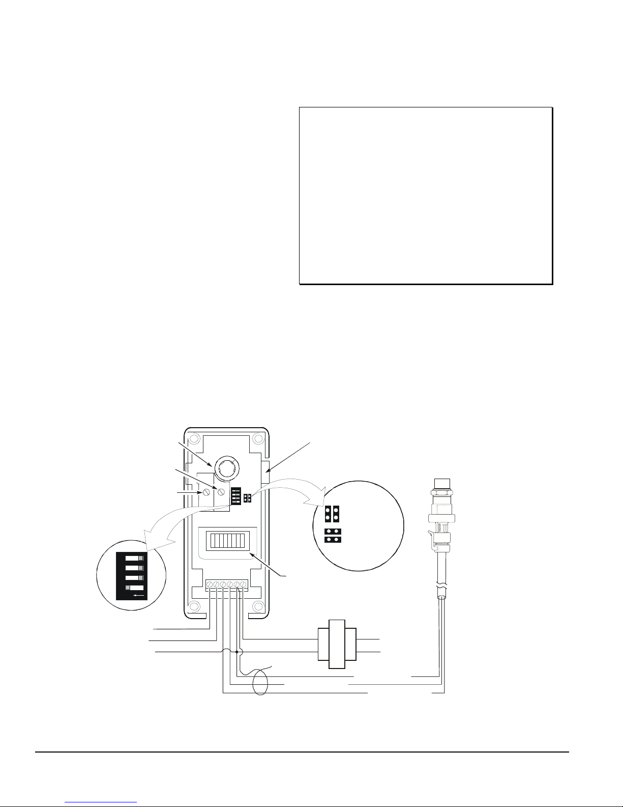
Setpoint Potentiometer
Minimum Output
Potentiometer
Throttling Range
Potentiometer
Integration
DIP Switch
43
21
O
N
0 to 10 VDC Output
0 to 20 mA Output
Common for Analog
Outputs
Module Connector
J1 Jumper
Positions
LED Indicator
24 VAC Transformer
(If a Y350R Power Module
Red wire to VDC
Reverse Acting
Direct Acting
is not used)
120/240 VAC
Black wire to C
White wire to SN
THROT
RANGE
OUTPUT
I
V
MIN
PSI
SN
VDC
24V
C
(Percent of Output)
24 VAC
Connect Cable
Shield to C
Figure 2: Interior View and Typical Wiring of P352PN Control
P399
Transducer
WHA-P 399
Wiring Harness
2
Basic Controls—P352PN Electronic Proportional Plus Integral Pressure Controls for PSI Applications
Page 3

Proportional-Only Controls
Proportional Plus Integral Controls
Proportional-only controls work by continuously
adjusting the magnitude of the control’s output signal in
proportion to the difference (input-error) between the
control’s setpoint value and the actual value sensed in
the controlled system. As load on a system increases,
the input-error to the control increases. The control
reacts by increasing the magnitude of the output
signal, driving the controlled device to respond to the
increased load. (See Figure 3.)
The advantages of proportional-only controls are that
they are easy to set up and adjust, and they provide
good stability and rapid response to changing load
conditions.
A disadvantage of proportional-only controls is they
can not maintain a system process at the exact control
setpoint. A proportional offset (or droop) is always
present when there is a steady load on the controlled
system. (See Figure 3.)
The result is that a proportional-only control maintains
a system process at a control-point instead of the
desired setpoint. Control-point is setpoint plus the
proportional offset. The greater the load on the system,
the greater the proportional offset and the further the
control-point is from the system setpoint. A
proportional-only control can not adjust the output
signal to drive a system process from the control-point
to the desired setpoint. (See Figure 3.)
Systems with proportional-only controls and large
loads or highly variable load conditions may operate at
control-points that vary significantly from the desired
setpoint.
The P352PN proportional plus integral (PI) pressure
control incorporates integral (or reset) control action
along with proportional-only control action. The
advantage to this is that the PI design effectively
eliminates proportional offset, and the PI control can
adjust the output signal to not only match a steady load
on the system, but also drive the system process
towards setpoint. On a properly sized system with
steady load conditions, a PI control can maintain the
system process very close to the system setpoint. (See
Figure 3.)
The speed at which the PI control drives the system
process to setpoint (recovery rate) is determined by
the system’s capacity, the size of the load, and the
integration constant set on the PI control.
The integration constant establishes the rate at which
the control re-adjusts to the load as it drives the
process towards setpoint. The faster the integration
constant, the faster the control re-adjusts the
magnitude of the output signal, and the faster the
recovery rate of a properly sized and setup system.
On traditional PI controls, the rate of re-adjustment can
become too large if the process load exceeds the
capacity of the equipment. When the controlled
equipment is at full capacity and the setpoint still
cannot be reached, traditional PI controls continue to
readjust the magnitude of the output signal. The result
is called
The P352PN Series proportional plus integral controls
avoid
dynamic ceiling on the integrator, which allows the
process to recover from an out-of-range condition
without experiencing a long period of overshoot.
integral windup
integral windup
.
with a patented circuit that puts a
Basic Controls—P352PN Electronic Proportional Plus Integral Pressure Controls for PSI Applications
It should be noted that PI controls might not be suitable
for all applications. Improperly applied PI controls may
be unstable and overshoot setpoint.
Also, PI controls require two separate adjustments that
are dependent on each other. The system must be
properly sized to handle the maximum process load,
and close observation is necessary when the PI
controls are initially set up and checked out. But on the
proper applications PI controls provide superior
accuracy and continuous setpoint control.
3
Page 4
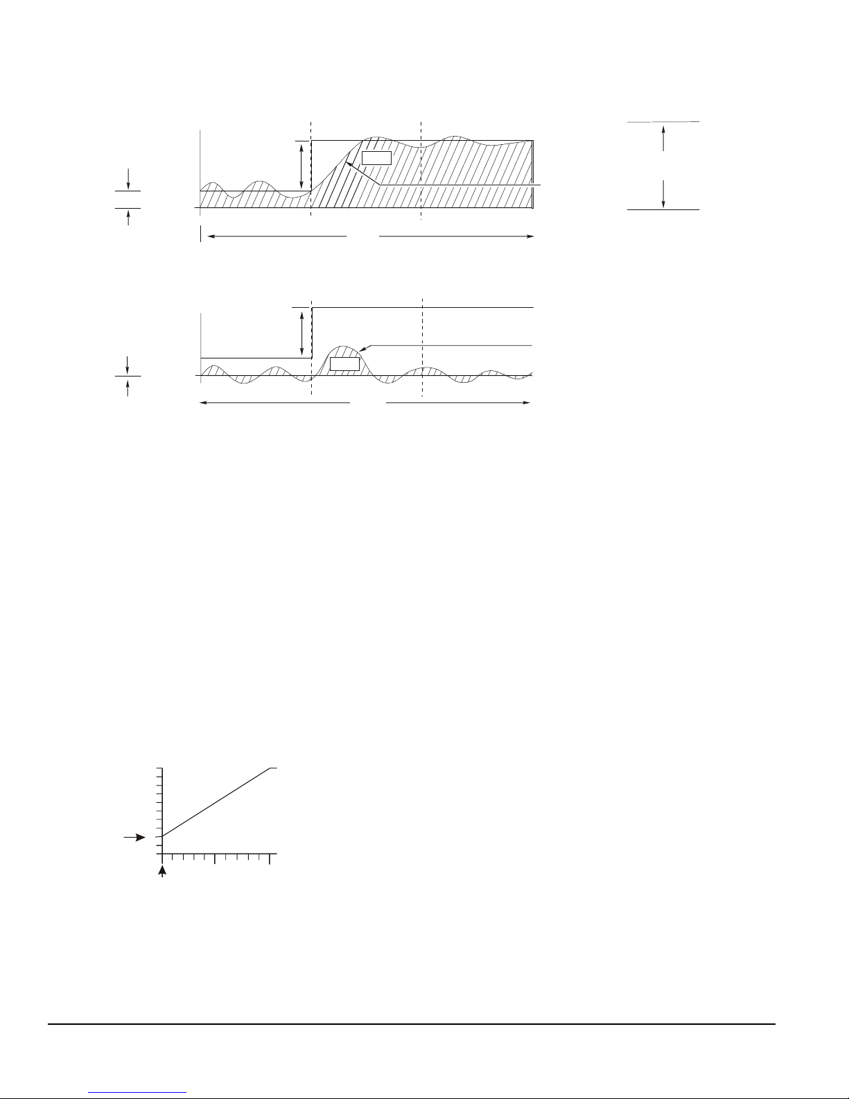
Temperature
Proportional Only Control
Proportional
Offset
Proportional
Offset = 0
Load Change
Setpoi nt
Temperature
Load Change
Setpoi nt
Error
Time
Proportional Plus Integral Control
Error
Time
Figure 3: Operation of Proportional Only vs. Proportional Plus Integral Control
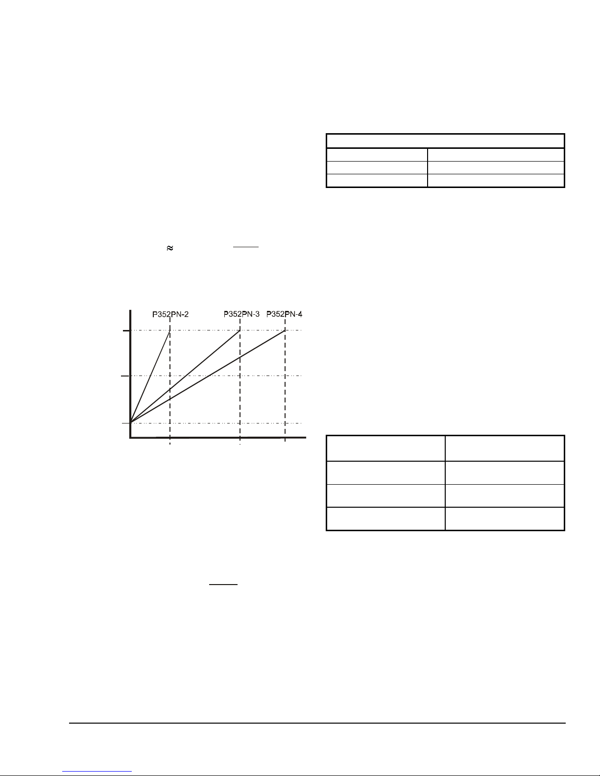
Minimum Output Adjustment and LED Bar
Graph Output Indicator
The minimum output adjustment sets the minimum
signal output (in VDC or mA) that the P352PN control
provides to the controlled device. The minimum output
can be set between 0 and 60% of the output range
(up to 6 VDC or 12 mA).
Example: For a controlled device that responds to a
4 to 20 mA output signal, the minimum output must be
4 mA or 20% of the 0 to 20 mA range. (See Figure 4.)
Adjust the MIN OUTPUT potentiometer located in the
center of the circuit board. The LED bar graph will
advance one LED segment for each 10% increase in
output range. The first segment lights at 10%, the
second segment at 20% and so on, until the tenth
segment lights at 100%.
Output
20
Range
(in mAs)
Minimum
Output
Setting (20%)
Minimum Output Set to 20% (4 mA) and
Throttling Range Set to 50 psi for P352PN-2
or 100 psi for P352PN-3 and P352PN-4.
10
4
0
Setpoi nt
Pressure
25
50
Throttling Range (psi)
50
100
(Range for
P352PN-2)
(Range for
P352PN-3 or
P352PN-4)
System Load
Throttling
Control Point
Follows the Load
System Load
Integration adjusts the
proportional output to
bring the process to
setpoint regardless of load.
Range
Throttling Range (Proportional Band)
On controls set for proportional only, the throttling
range or proportional band setting establishes how far
the system pressure must deviate from the P352PN
control setpoint to generate a 100% output signal from
the control.
Thus, on a proportional only control with a throttling
range setting of 25 psi, the output signal (VDC or mA)
is 0% when the system pressure equals the setpoint
pressure. The output signal increases to 100%
(10 VDC or 20 mA) when the system pressure rises
25 psi above the setpoint in DA mode, or drops 25 psi
below the setpoint in RA mode.
When setting up controls for proportional plus integral
operation, start with the integration constant OFF (in
the proportional only mode), and set the throttling
range (or proportional band) to a wide setting (60% or
more of the total range) to assure a stable control loop.
Then set the integration constant as slow as possible.
(Refer to
Adjust the throttling range by turning the THROT
RANGE potentiometer located under the control cover
on the center of the circuit board.
The throttling range can be adjusted from 5-50 psi on
the P352PN-2 model and 10-100 psi on the P352PN-3
and P352PN-4 models. (See Figures 4 and 5.)
Integration Constant DIP Switch Settings.
)
Figure 4: Minimum Output and Throttling Ranges for
the P352PN Controls
4
Basic Controls—P352PN Electronic Proportional Plus Integral Pressure Controls for PSI Applications
Page 5

Integration Constant DIP Switch Settings
Direct Acting or Reverse Acting Mode
Depending on the application, the P352PN control can
be set to operate as a proportional-only control or as a
proportional plus integral control. Refer to sections
Proportional-Only Controls
Integral Controls
.
Proportional Plus
and
The control has three different integration constants to
choose from, which allow you to setup the control for
the optimum recovery rate for your application. Use the
Integration DIP switch shown in Figures 2 and 5, and
the guidelines below to set the control for
proportional-only or set to the integration constant rate
for proportional plus integral control.
OFF: Switch 1 On and all others Off
•
provide
proportional only operation. In open-loop
applications, (without feedback) select
proportional-only operation. (See Figure 5.)
Slow: Switch 2 On and all others Off
•
is the
slowest integration constant and is suitable for
most proportional plus integral applications.
Slow
is the recommended initial setting.
Medium: Switch 3 On and all others Off
•
provides a faster integration constant. If the rate of
system recovery to setpoint is sluggish when the
control is set to Slow, and the system has enough
capacity to drive the process to setpoint at a faster
rate, the Medium setting may be used.
In Direct Acting (DA) mode, the analog output signal
magnitude increases as the pressure rises. In Reverse
Acting (RA) mode, the analog output signal magnitude
increases as the pressure drops. (See Figure 5.)
Select the desired mode of operation by positioning the
two jumpers on the J1 jumper block. Position the
jumpers vertically for Reverse Acting, or horizontally for
Direct Acting. (See Figure 2.)
The Reverse Acting/Direct Acting jumpers are installed
in the Reverse Acting position at the factory.
Note: Dashed areas show throttling range possibilities
from minimum to maximum.
Reverse Acting Direct Acting
RA
(-)
10100
Setpoi nt
Throttling Range
(psi)
10
VDC
0
0
20
mA
10
0
20
mA
10
0
10
VDC
0
0
Setpoi nt
DA
(+)
10
Throttling Range
100
(psi)
Figure 6: Reverse and Direct Acting Throttling
Ranges (Proportional Bands) Shown in
Proportional Only Mode
(Model Depicted has 10-100 psi Throttling Range)
• Fast: Switch 4 On and all others Off
is the
fastest integration constant. This should be used
only in instances where the rate of change at the
transducer is extremely rapid and system capacity
is sufficient to compensate for rapid load changes.
FAST
MEDIUM
SLOW
OFF
(Proportional
Only)
O
43
21
N
Figure 5: DIP Switch for Setting Integration
Constant or Proportional Only Control
(Switch shown is set for Proportional Only Control)
Basic Controls—P352PN Electronic Proportional Plus Integral Pressure Controls for PSI Applications
5
Page 6

imensions
D
Mounting Slots
for No. 6 Screws
3/16 (4)
1/2 (13)
2-15/16
(75)
5 (127)
P352P
•
The P352PN control can output a variable signal
from 0 to10 VDC or 0 to 20 mA. Connections are
made to the terminal block located in the wiring
compartment at the bottom of the case.
•
Both the voltage and milliampere outputs can be
used at the same time, allowing the P352PN
control to drive two independent devices
simultaneously (off the same RA or DA ramp).
This feature may be used to drive different types of
motor actuators or variable speed drives.
1-9/16
(40)
DIN Rail Mounts
7/16 (11)
2-3/8 (61)
7/8 (22)
2-3/8 (61)
1-3/16
(31)
1/2 in. Tradesize
Conduit Opening
Figure 7: P352PN Control Dimensions, in. (mm)
nstallation and Wiring
I
The P352PN control is housed in a compact NEMA 1
plastic enclosure designed for standard 35 mm DIN rail
mounting. The control is not position sensitive but
should be mounted for convenient wiring and
adjustment. Four key-slot mounting holes on the back
of the control case are provided should surface
mounting be required.
Note: When mounting the P352PN control (or any
System 350 Module) to rigid conduit, attach
the hub to the conduit before securing the hub
to the control enclosure.
Table 1: P352PN Control Wiring Terminal
Designations
Terminal
Designation
V
I
SN
VDC
C
24V
Terminal Description
0 to 10 VDC output signal
0 to 20 mA output signal
0.5 to 4.5 VDC input signal from the
pressure transducer
5 VDC power supply to the
pressure transducer
Common for the pressure transducer
and output signals
24 volts AC
Wiring the Transducer
The P352PN controls use a P399 Pressure
Transducer to generate the 0.5 to 4.5 VDC input
signal. The transducer is wired to the control at the
terminal block at the bottom of the circuit board. Refer
to Table 2 and Figure 2 for proper wiring configuration.
Connect the cable shield to C on the terminal block.
!
WARNING:
Risk of Electrical Shock.
This control, and any modules
connected to it, may have more
than one power supply.
Disconnect all power supplies
before making electrical
connections to avoid possible
electrical shock or equipment
damage.
•
All wiring must be installed to conform to the
National Electrical Code and local regulations. For
maximum electrical rating of control, see label
inside the control cover. Use copper conductors
only.
6
Basic Controls—P352PN Electronic Proportional Plus Integral Pressure Controls for PSI Applications
The maximum recommended length of 22 AWG
shielded transducer cable is 250 ft (76 m). Refer to the
P399 Electronic Pressure Transducer
Product/Technical Bulletin (LIT-125515)
for more
information about the pressure transducer.
Table 2: P399 Transducer Connections
Terminal and Wire Designations
P352PN Control
Terminals
SN
VDC
C
Transducer Cable
White
Red
Black
Page 7

dd-on System 350 Modules
A
The D352 Digital Pressure Display Module, S352AA-2
Stage Module, and Y350R Power Module are designed
to connect together and plug into the P352PN control.
The power module connects to the control via a
connector on the control’s right side. The display
module and stage module connects to the right side of
the power module.
D352 Pressure Display Module
The D352 display module receives its power, pressure,
and setpoint information from the P352PN control. A
3-digit Liquid Crystal Display (LCD) gives continuous
read-out of the sensed pressure. Pushing the PRESS
FOR SETPOINT button on the display module displays
the P352PN control setpoint. Refer to
D350 Display Modules Product/Technical Bulletin,
LIT-930070
for more information.
System 350
Y350R Power Module
The Y350R power module provides a convenient
method of powering System 350 Modules from a
120 or 240 VAC power source. The power module
supplies power to all of the modules. Refer to
System 350 Y350R Power Module Product/Technical
Bulletin, LIT-930090
, for more information.
S352AA-2 ON/OFF Stage Module
The S352AA-2 stage module provides ON/OFF
pressure control based on the P5352PN control
setpoint and the stage module offset. Refer to
System 350 S350A Temperature, S351A Humidity,
and S352A Pressure Stage Modules
Product/Technical Bulletin, LIT-930080
information.
djustments
A
Use the following procedure to set up and adjust the
P352PN pressure control.
1. Remove its cover by loosening the four captive
cover screws.
2. Set the RA/DA jumper blocks to the desired mode.
Position the jumper blocks vertically for RA or
horizontally for DA mode. See
Acting Mode
3. Adjust the throttling range potentiometer to desired
setting. Rotate clockwise to increase the throttling
range. Refer to
Band)
section and Figure 2.
Throttling Range (Proportional
section and Figure 2.
, for more
Reverse or Direct
Note: If the P352PN control is to be used in
proportional plus integral mode, the initial
throttling range adjustment should not be set
below 30 psi for the P352PN-2 model or 60 psi
for the P352PN-3 and P352PN-4 models. A
narrow proportional band used in conjunction
with the integration may result in unstable
control.
4. If minimum output is required, set the minimum
output potentiometer to the desired position. The
10-segment LED bar graph or a voltmeter can be
used to read the minimum output. See
Output Adjustment
Note: Before setting the minimum output, verify
that the minimum output potentiometer is
set to zero (turned fully counterclockwise),
and that no LEDs are lit on the LED bar
graph.
For each 10% increase in output, the LED bar
graph will advance one LED segment
(only one bar is lit at anytime). In a milliampere
application, each bar equals 2 mA. In a voltage
application, each bar equals 1 VDC.
Example: To set the control for a minimum output
of 4 mA, slowly turn the minimum output
potentiometer clockwise until the second LED
segment just lights.
5. Adjust the P352PN control to the desired setpoint,
replace cover, and place the system in operation.
Table 3 gives the tolerances for setpoint readings
at mid scale and scale-end.
Note: The D352 Display Module is unaffected by
these tolerance shifts. Use the display module
to achieve the most accurate setpoint
selection.
section and Figure 2.
Minimum
Table 3: Setpoint Mid-scale and Scale-end
Tolerance Values
Control
Model
P352PN-2
P352PN-3
P352PN-4
6. Make sure the operating system is stable before
setting the integration constant (if necessary).
Refer to the
Integration Constant DIP Switch Settings
setting the integration constant.
Mid-scale
Tolerance
±1.5 psi ±2.5 psi
±1.5 psi ±3.5 psi
±3.5 psi ±8 psi
Checkout Procedure
Scale-end
Tolerance
section and
when
Basic Controls—P352PN Electronic Proportional Plus Integral Pressure Controls for PSI Applications
7
Page 8

heckout Procedure
C
Proportional-only and proportional plus integral
controls should be carefully set up and then check out
during system operation. Use the following guidelines
to check out the P352PN controls:
1. Before applying power, make sure installation and
wiring connections are according to job
specifications.
2. After all electrical connections have been checked,
and any necessary adjustments have been made,
put the system in operation and observe at least
three complete operating cycles to determine that
the system is stable.
3. If integration is required, select slow, medium, or
fast. The slow integration constant is the
recommended initial setting. (Refer to the
Integration Constant DIP Switch Settings
4. Put the system back into operation. Observe system
operation and make any additional adjustments
necessary to obtain stable process control.
roubleshooting
T
If the System 350 control modules do not appear to
function properly, verify that the proper mode
(RA or DA) has been selected on each control module.
Then perform the following procedures (in the listed
order) to determine the problem.
IMPORTANT: The control and the controlled
equipment must be powered, and
operating at a stable pressure to
perform many of the following
procedures.
!
WARNING:
Risk of Electrical Shock.
To perform many of the following
procedures it is necessary to
power the control and the
controlled equipment while the
control cover is removed. Do not
touch any exposed metal control
components with anything other
than properly insulated tools or
insulated probes of the digital
voltage meter. Failure to use
properly insulated tools and
probes can result in severe
electrical shock.
section.)
Equipment Needed:
•
reliable pressure gauge connected near the
transducer
•
reliable and accurate Digital Voltmeter (DVM)
capable of measuring AC voltage and DC voltages
down to + or – 0.1 VDC in the 0 to 10 VDC range
1. Check for proper supply voltage to the P352
Control.
a. Before powering control and equipment, check
to assure that all of the wiring is correct and all
of the connections are tight.
b. With the DVM, check the voltage between the
24V
and the
block on the upper left side of the control.
If an external 24 VAC transformer powers
the P352 control
The voltage should be between 20 and 30 VAC.
If a Y350R Power Module powers the P352
control
voltage should be between 16 and 38 VDC.
c. If the DVM reading is within the indicated
voltage range, proceed to Step 2.
d. If the DVM reading is
voltage ranges, replace the external
transformer or the Y350R Power Module, and
recheck for proper supply voltage.
2. Check the for proper supply voltage to the
pressure transducer.
a. Select DC volts on the DVM and measure the
voltage between
on the terminal block on the upper left side of
the control.
The voltage should be 5.0 VDC
(+ or – 0.1 VDC). If the voltage is in this range
proceed to Step 3.
b. If the voltage is out of this range, power down
the controlled equipment and disconnect it
from the control. Disconnect the transducer
from the control. With the control powered,
measure the voltage between
COM
terminals on the terminal block on the
upper left side of the control.
The voltage should be 5.0 VDC
(+ or – 0.1 VDC). If the voltage is in this range,
replace the transducer.
c. If the voltage is out of range, replace the
control.
COM
terminals on the terminal
, select AC volts on the DVM.
, select DC volts on the DVM. The
not
within the indicated
VDC
and the
COM
VDC
terminals
and the
8
Basic Controls—P352PN Electronic Proportional Plus Integral Pressure Controls for PSI Applications
Page 9
3. Check pressure transducer for proper output
signal voltage.
a. Measure and record the voltage between the
SEN
and the
terminal block.
COM
terminals on the control
V
= _______
o
b. At the same time observe and record the
psi
pressure reading.
c. The transducer output signal voltage (
= _______
T
V
)
o
increases proportionally to an increase in the
pressure at the transducer (
psi
T
). Use the
graph in Figure 8 to compare the measured
signal voltage to the measured pressure. Or
use the formula below to compare the voltage
and pressure values.
P
max
4V
500 psi
750 psi
Signal Output Voltage
4.5 VDC
(90%)
2.5 VDC
(50%)
(% of Supply VDC)
0.5 VDC
(10%)
psi
psi
= Pressure measured at transducer
T
V
= Transducer output signal voltage (VDC)
o
P
= Transducer pressure range maximum
max
(V - 0.5V) x
o
T
Control Model Number
100 psi
Pressure Range
Figure 8: Transducer Pressure vs.
Output Signal Voltage
Example:
The measured pressure at the gauge is
approximately 245 psi, the measured voltage
is 2.5 VDC (
range is 0 to 500 psi (
V
), and the transducer’s rated
o
P
). Use the formula
max
above to calculate the pressure you would
expect from the measured voltage.
psi
(2.5V - 0.5V) x
500
4V
= 250
psi
Since the measured pressure of 245 psi is
close to the pressure calculated from the
measured voltage (250 psi), the transducer
output voltage should be considered within the
desired range.
4. Check the P352PN control for proper operation.
Perform Steps 1-3 first.
a. Record the current setpoint, integration
constant, and throttling range in Table 4 below.
Table 4: Record of Current Settings
Current P352PN Control Settings
Setpoint
Integration Constant
Throttling Range
b. Set integration constant to OFF (proportional
only). See
Integration Constant
section.
c. Disconnect all power to the system and
control.
d. Disconnect the equipment from the control.
e. Reconnect power to the control.
f. Verify that the power supply and transducer
are connected properly.
g. Use an accurate gauge to take an independent
pressure reading at the transducer. (This
procedure requires a minimum of 30 psi static
pressure at the transducer.)
h. Set the P352PN control to Direct Acting mode.
Refer to Figure 2.
i. Adjust the throttling range potentiometer to
approximately 25 psi.
j. Observe the LED display while adjusting the
setpoint for each of the settings listed in
Table 5. If the display varies substantially from
these values, replace the control.
Table 5: Output at Select Setpoint Settings
Setpoint Setting
At or Above Transducer
Reading
12 to 13 psi Below
Transducer Reading
25 psi Below Transducer
Reading
k. Reconnect the equipment to the control. Reset
the control to the original settings (Table 4),
and reconnect power to the system.
l. Observe the system for a minimum of three
operating cycles. If the system still does not
perform properly, check application settings,
and replace the control if it does not operate
as expected for those settings.
Approximate Output
Expected
No LED bars lit
4 or 5 LED bars lit
All LED bars lit
Basic Controls—P352PN Electronic Proportional Plus Integral Pressure Controls for PSI Applications
9
Page 10

5. Check the stage modules for proper operation.
If stage modules are not used, skip this step.
Perform Steps 1-4 first.
a. Determine and record if the control is
in the DA or RA mode of operation.
b. Determine the differential setting.
c. Observe and record the offset setting.
d. Observe and record the system
pressure at the gauge.
If the stage module is in the DA mode
e.
adjust the setpoint setting to a value lower than
the observed gauge pressure. If the stage
module LED is not lit, turn the control setpoint
adjustment knob counterclockwise until the
LED lights.
f. With the stage module LED lit, slowly turn the
control setpoint adjustment knob clockwise
(to increase the setpoint setting) until the LED
goes off. Observe the control setpoint, which
should be the same as the gauge pressure
minus the offset setting when the stage
module LED goes off.
g. Next turn the setpoint adjustment slowly
counterclockwise until the stage module LED
lights again. Observe the control setpoint,
which should be equal to the gauge pressure
minus the differential setting and offset setting
when the LED is lit.
If the control is in the RA mode
h.
setpoint setting to a value higher than the
observed gauge pressure. If the stage module
LED is not lit, turn the setpoint adjustment
knob clockwise until the LED lights.
, adjust the
,
i. With the stage module LED lit, slowly turn the
setpoint adjustment knob counterclockwise
(to decrease the setpoint setting) until the LED
goes off. Observe the control setpoint, which
should be equal to the gauge pressure plus
the offset setting when the LED went off.
j. Next turn the setpoint adjustment slowly
clockwise until the stage module LED lights
again. Observe the control setpoint, which
should be equal to the gauge pressure plus
the offset and differential settings.
6. Check the display module for proper operation.
If a display module is not used, skip this step.
Perform Steps 1-5 first.
a. Check the gauge pressure at the transducer
(psi).
b. If the display module does
(approximate) pressure measured at the
gauge, replace the display module.
c. Pressing the button on the display module
should display the current setpoint setting.
d. If the displayed setpoint is out of the control’s
setpoint pressure range (check scale-plate at
the setpoint knob for control’s pressure range)
replace the control.
e. If pressing the SETPOINT button results in a
reading other than the expected setpoint
value, check the setpoint setting and correct if
necessary. If the display continues to read an
incorrect value, replace the display module.
Note: If the control and add-on modules all appear to
be operating properly, but the field device still
does not turn on and off as expected, check
the wiring from the control or stage module to
the field device.
not
display the
Table 6: S352AA-2 Stage Module Output Relay Troubleshooting
Operating Mode LED N.O. Contact Position Setpoint Setting equals approximately…
Reverse Acting (RA)
Reverse Acting (RA)
Direct Acting (DA)
Direct Acting (DA)
epairs and Replacement
R
Do not make field repairs or perform calibration. The
P352PN Pressure Controls and the P399 Transducer
are available through local Johnson Controls
representatives.
10
Basic Controls—P352PN Electronic Proportional Plus Integral Pressure Controls for PSI Applications
ON Closed (gauge pressure) + offset + differential
OFF Open (gauge pressure) + offset
ON Closed (gauge pressure) - offset - differential
OFF Open (gauge pressure) - offset
Page 11

Table 7: Ordering Information
Item
Electronic
Proportional Plus
Integral Pressure
Controls for PSI
Applications
Display Module
Power Module
Stage Module
Pressure
Transducers
Wiring Harnesses
Conduit Adapter
DIN Rail Section
DIN Rail End
Clamps
Cable for Remote
Mounting of
D352 Display
Module
Product Code
Number
P352PN-2C
P352PN-3C
P352PN-4C
D352AA-2C Digital Pressure Display Module with 0-750 psi Scale
Y350R-1C 120/240 VAC, 50/60 Hz input
S352AA-2C ON/OFF Pressure Controlled Stage module with SPDT Output Relay
P399AAA-1C
P399AAC-1C
P399BAA-1C
P399BAC-1C
P399CAA-1C
P399CAC-1C
WHA-P399-200C
WHA-P399-400C
ADP11A-600R 1/2 in. Snap-fit EMT Conduit Adapter (box of 10)
BKT287-1R
BKT287-2R
PLT344-1R Consists of Two End Clamps
WHA29A-600R
WHA29A-603R
WHA29A-604R
Setpoint Range: 0-100 psi
Throttling Range: 5-50 psi
Setpoint Range: 90-250 psi
Throttling Range: 10-100 psi
Setpoint Range: 240-600 psi
Throttling Range: 10 to 100 psi
Note: Controls do not include pressure transducer or wiring harness.
Used with P352PN-2 control. Fitting: 1/8 in. NPT
Used with P352PN-2 control. Fitting: 1/4 in. SAE Female with valve depressor
Used with P352PN-3 control. Fitting: 1/8 in. NPT
Used with P352PN-3 control. Fitting: 1/4 in. SAE Female with valve depressor
Used with P352PN-4 control. Fitting: 1/8 in. NPT
Used with P352PN-4 control. Fitting: 1/4 in. SAE Female with valve depressor
Note: Wiring harness must be purchased separately.
6 ft 6-1/2 in. (2 m)
13 ft 3 in. (4 m)
35 x 7.5 mm standard DIN rail, 12 in. (0.305 m) long
35 x 7.5 mm standard DIN rail, 36 in. (0.914 m) long
3 ft (0.9 m)
25 ft (7.6 m)
50 ft (15.2 m)
Description
Basic Controls—P352PN Electronic Proportional Plus Integral Pressure Controls for PSI Applications
11
Page 12

pecifications
S
Product
Setpoint and
Throttling Ranges
Supply Power
Requirements
Add-on Modules:
Y350R Power Module
D352 Display Module
S352AA-2 Stage Module
Analog Output
Minimum Output Signal
Magnitude
Output Indication
Control Action
Integration Constant
Ambient Temperature
Ambient Humidity
(all modules)
Material
Agency Listings
P352PN Electronic, Proportional Plus Integral Pressure Controls for PSI Applications
P352PN-2: Setpoint Range 0-100 psi; Throttling Range 5-50 psi
P352PN-3: Setpoint Range 90-250 psi; Throttling Range 10 to 100 psi
P352PN-4: Setpoint Range 240-600 psi; Throttling Range 10 to 100 psi
AC Supply: 24 VAC Class 2, 50/60 Hz, (20 to 30 VAC) 5 VA (for P352PN control only)
Y350R Power Module: See
Input Voltage: 120/240 VAC, 50/60 Hz
Display Range of 0 to 750 psi
SPDT Enclosed Output Relay rated for 10 A Non-inductive, 125 VA Pilot Duty-24/240 VAC,
1/2hp 120/240 VAC
0 to 10 VDC (550 ohm Load Minimum) and 0 to 20 mA (600 ohm Load Maximum)
Adjustable from 0 to 60% of Full Output Signal Range
A 10-segment LED bar graph indicates percentage of output.
Direct or reverse action is jumper selectable.
Three Selectable Integration Constants: Slow, Medium, Fast, and an OFF (or Proportional
Only Control) Position
Operating: -30 to 150°F (-34 to 66°C)
Shipping: -40 to 185°F (-40 to 85°C)
0 to 95% RH Non-condensing; Maximum Dew Point: 85°F (29°C)
Case, Cover: NEMA 1 High-impact Thermoplastic
UL Listed, CCN XAPX, File E27734
UL Listed for Canada, CCN XAPX7, File E27734
Add-on Modules
below.
The performance specifications are nominal and conform to acceptable industry standards. For application at conditions beyond these
specifications, consult Johnson Controls/PENN Application Engineering at (414) 274-5535. Johnson Controls, Inc. shall not be liable for
damages resulting from misapplication or misuse of its products.
Controls Group FAN 930
507 E. Michigan Street System 350 Product Guide
P.O. Box 423 Printed in U.S.A.
Milwaukee, WI 53201 www.johnsoncontrols.com
12
Basic Controls—P352PN Electronic Proportional Plus Integral Pressure Controls for PSI Applications
 Loading...