

Page 1

P2000
Security Management System
DVR Integration
Version 3.10 and higher, June, 2010
24-10515-13 Revision –
Page 2

Page 3

P2000
Security Management System
DVR Integration
Version 3.10 and higher, June, 2010
24-10515-13 Revision –
Security Solutions
(805) 522-5555
www.johnsoncontrols.com
Page 4

Copyright 2010
Johnson Controls, Inc.
All Rights Reserved
No part of this document may be reproduced without the prior permission of Johnson Controls, Inc.
Page 5

Acknowledgment
Declaration of Conformity
This product complies with the requirements of the European Council Electromagnetic
Compatibility Directive 2004/108/EEC and the Low Voltage Directive 2006/95/EEC.
This equipment must not be modified for any reason and it must be installed as stated in the
Manufacturer’s instruction.
If this shipment (or any part thereof) is supplied as second-hand equipment, equipment for sale
outside the European Economic Area or as spare parts for either a single unit or system, it is not
covered by the Directives.
Cardkey P2000, BadgeMaster, and Metasys are t
All other company and product names are trademarks
respective owners.
If this document is translated from the original English version by Johnson Controls, Inc., all
reas
onable endeavors will be used to ensure the accuracy of translation. Johnson Controls, Inc.
shall not be liable for any translation errors contained herein or for incidental or consequential
damages in connection with the furnishing or use of this translated material.
Due to continuous development of our products, the information in this document is subject to
ange without notice. Johnson Controls, Inc. shall not be liable for errors contained herein or
ch
for incidental or consequential damages in connection with furnishing or use of this material.
Contents of this publication may be preliminary and/or may be changed at any time without any
obligation to notify anyone of such revision or change, and shall not be regarded as a warranty.
rademarks of Johnson Controls, Inc.
or registered trademarks of their
Page 6

Page 7

TABLE OF CONTENTS
Chapter 1: Introduction
About This Manual................................................................................................................................... 1-1
Manual Summary............................................................................................................................. 1-1
Note on Other Manufacturer’s Documentation................................................................................. 1-2
Technical Support ............................................................................................................................ 1-2
Manual Conventions ........................................................................................................................ 1-2
DVR Overview ......................................................................................................................................... 1-2
Important Installation Notes ..................................................................................................................... 1-3
Hardware Requirements .......................................................................................................................... 1-3
Supported Protocols ................................................................................................................................ 1-4
DVR Integration Components .................................................................................................................. 1-7
Defining System Hardware for the DVR Integration ................................................................................1-7
Namespace and Database............................................................................................................... 1-8
Relationship Between the Namespace and Database..................................................................... 1-8
DVR Naming Conventions ............................................................................................................... 1-9
Naming Items for the AV Server Namespace .................................................................................. 1-9
Defining the Number of Namespace Items .................................................................................... 1-10
Chapter 2: Configuration
DVR Configuration Overview ................................................................................................................... 2-1
Using the CCTV/AV Configuration Window ..................................................................................... 2-1
Configuring DVR Components................................................................................................................. 2-3
General Configuration Notes............................................................................................................ 2-3
CCTV Server.................................................................................................................................... 2-4
Edit Server Field Definitions..................................................................................................... 2-5
AV Switches..................................................................................................................................... 2-5
Creating and Configuring AV Switches.................................................................................... 2-5
Edit AV Switch Field Definitions............................................................................................... 2-8
Cameras......................................................................................................................................... 2-14
Creating and Configuring Cameras........................................................................................ 2-14
Edit AV Camera Field Definitions........................................................................................... 2-16
Tabs for Alarm Options ..........................................................................................................2-19
Camera Presets ............................................................................................................................. 2-20
Monitors ......................................................................................................................................... 2-20
Creating and Configuring Monitors ........................................................................................ 2-21
Edit AV Monitor Field Definitions............................................................................................ 2-22
Dry Contact .................................................................................................................................... 2-22
Edit AV Dry Contact Field Definitions..................................................................................... 2-25
Alarm Options for DVR Components ............................................................................................. 2-26
Alarm Options Field Definitions.............................................................................................. 2-26
24-10515-13 Rev. – v
This document contains confidential and proprietary information of Johnson Controls, Inc.
© 2010 Johnson Controls, Inc.
Page 8

Table of Contents DVR Integration Option
Chapter 3: Operation
Using P2000 Functions............................................................................................................................ 3-1
DVR Event Actions .................................................................................................................................. 3-2
Displaying Items in the Real Time Map ................................................................................................... 3-5
Associating Cameras to Input Points or Terminals .................................................................................. 3-7
Executing AV Player .............................................................................................................................. 3-10
Executing AV Player from the Real Time List ................................................................................ 3-10
Executing AV Player from the Real Time Map............................................................................... 3-11
Executing AV Player from the Alarm Monitor................................................................................. 3-11
Executing AV Player from the Options Menu................................................................................. 3-12
AV Player Components and Functions.................................................................................................. 3-12
Main Menu ..................................................................................................................................... 3-13
Saving the Recording............................................................................................................. 3-13
Video Display Aspect Ratio.................................................................................................... 3-14
Video Player................................................................................................................................... 3-14
AV Player Functions....................................................................................................................... 3-14
Viewing Modes............................................................................................................................... 3-15
Minimal Features Mode.......................................................................................................... 3-15
Full Features Mode ................................................................................................................ 3-16
Live Video Monitoring..................................................................................................................... 3-16
Monitor Selection ........................................................................................................................... 3-17
Video Search and Retrieval ........................................................................................................... 3-17
PTZ and Presets Control................................................................................................................ 3-18
Troubleshooting P2000 AV Player......................................................................................................... 3-20
Chapter 4: Protocol Integration
DVN 5000 ................................................................................................................................................ 4-1
Compatibility with DVN 5000 Series ................................................................................................ 4-1
Additional Notes............................................................................................................................... 4-2
Genetec ................................................................................................................................................... 4-3
General Notes.................................................................................................................................. 4-3
Defining Dry Contacts ...................................................................................................................... 4-3
Genetec Alarm Messages................................................................................................................ 4-4
P2000 Alarm Messages................................................................................................................... 4-4
Changing Default Alarm Logical IDs ................................................................................................ 4-5
Creating Custom Logical IDs ................................................................................................... 4-6
Verint Loronix and SmartSight ................................................................................................................. 4-7
Troubleshooting Loronix DVR.......................................................................................................... 4-7
Configuration Requirements .................................................................................................... 4-9
Milestone................................................................................................................................................ 4-11
Configuring Camera for Motion Alarm............................................................................................ 4-11
Milestone Viewer............................................................................................................................ 4-11
Troubleshooting the Milestone Integration..................................................................................... 4-14
Nextiva................................................................................................................................................... 4-14
Nice........................................................................................................................................................ 4-16
NiceVision Integration with P2000 ................................................................................................. 4-16
Configuration Guidelines for Nice v10.5 and v10.7........................................................................ 4-16
Configuring AV Switch ...........................................................................................................4-16
Configuring Cameras .............................................................................................................4-17
Configuring Presets................................................................................................................ 4-17
vi 24-10515-13 Rev. –
This document contains confidential and proprietary information of Johnson Controls, Inc.
© 2010 Johnson Controls, Inc.
Page 9

DVR Integration Option Table of Contents
Troubleshooting Nice 9.0 DVR....................................................................................................... 4-17
Known Limitations .................................................................................................................. 4-19
Panasonic ND300 and ND300A ............................................................................................................ 4-20
Pelco X-Portal Endura ........................................................................................................................... 4-21
Appendix A: Namespace Definitions
Flags ........................................................................................................................................................A-1
DVR Namespace Tags ............................................................................................................................A-2
DVR Channel Namespace Tags.............................................................................................................. A-5
Appendix B: Recording Quality
24-10515-13 Rev. – vii
This document contains confidential and proprietary information of Johnson Controls, Inc.
© 2010 Johnson Controls, Inc.
Page 10

Table of Contents DVR Integration Option
viii 24-10515-13 Rev. –
This document contains confidential and proprietary information of Johnson Controls, Inc.
© 2010 Johnson Controls, Inc.
Page 11

Chapter
1
INTRODUCTION
The Digital Video Recording (DVR) integration is an advanced feature that allows
authorized P2000 users to manage camera functions from a P2000 workstation, as well as to
link P2000 events and triggers to live audio-visual recordings.
ABOUT THIS MANUAL
This manual is a supplement to the P2000 documentation and details the information
concerning the Digital Video Recording (DVR) integration.
Manual Summary
The manual is divided into the following chapters:
Chapter 1: Introduction, defines conventions used throughout the manual,
lists the DVR hardware requirements and supported protocols, as well as
describes the DVR components. This chapter also contains information on
how to contact technical support.
Chapter 2: Configuration, describes the steps required to define DVR
components.
Chapter 3: Operation, provides information on using the DVR integration,
including detailed information about the AV Player.
Chapter 4: Protocol Integration, offers protocol-specific configuration and
operation tips.
Chapter A: Namespace Definitions, contains information about the DVR
namespace tags and flags.
Chapter B: Recording Quality, contains a table to help you determine
recording quality settings.
NOTE
Depending on the software version you are using, the screen captures
depicted in this manual may differ slightly.
24-10515-13 Rev. – 1-1
This document contains confidential and proprietary information of Johnson Controls, Inc.
© 2010 Johnson Controls, Inc.
Page 12

Introduction DVR Integration Option
!
CAUTION
Cautions remind you that certain actions, if not performed exactly as
stated, can cause damage to equipment, security problems, or cause
the system to operate incorrectly due to errors in system setup or
programming.
Note on Other Manufacturer’s Documentation
Johnson Controls does not duplicate documentation of other equipment
manufacturers. When necessary, as in this installation procedure, Johnson Controls
provides documentation that supplements that of other manufacturers. When
unpacking your equipment, keep all original manufacturer documentation for
future reference.
Technical Support
Technical assistance is provided to Johnson Controls authorized dealer
representatives from 5 a.m. PT (Pacific Time) to 5 p.m. PT Monday through Friday.
System users can get answers to operator questions by calling the local Johnson
Controls Inc. sales/service office.
The authorized dealer representatives can also provide you with information on the
maintenance contracts
and the on-site field service.
Manual Conventions
The following items are used throughout this manual to indicate special
circumstances, exceptions, important points regarding the equipment or personal
safety, or to emphasize a particular point.
NOTE
Notes indicate important points or exceptions to the information provided in
the main text.
DVR OVERVIEW
P2000 provides seamless integration with approved Digital Video Recording (DVR)
systems. The integration allows authorized users to manage camera functions, including
frame rate and resolution, from a single P2000 workstation, as well as to tie an event
generated on P2000 to live audio-visual (AV) recording. Depending on the DVR equipment
used, it also enables the user to search, retrieve, and download real time or archived AV
recording from any transaction or surveillance camera, from any place, at any time.
1-2 24-10515-13 Rev. –
This document contains confidential and proprietary information of Johnson Controls, Inc.
© 2010 Johnson Controls, Inc.
Page 13

DVR Integration Option Introduction
Audio-visual files can be recalled by a variety of query options, including date and time,
alarm events, camera ID, or DVR ID. Live video and audio playback options are available
from the Alarm Monitor, Real Time List, and Real Time Map.
The DVR system communicates with the P2000 server via a TCP/IP connection. The
communication is provided by the P2000 CCTV Server, a software component that is
selected and installed alongside the P2000 installation. Additionally, the DVR feature can
be configured with a CCTV Switch for added control of the CCTV cameras and monitors.
For more information on CCTV refer to the P2000 Software User Manual.
IMPORTANT INSTALLATION NOTES
Do not install third party vendor's workstation or server software on the P2000 server. In
addition, it is highly recommended that you do not install the third party DVR client software
and the P2000 workstation software on the same machine.
HARDWARE REQUIREMENTS
To operate the DVR feature in P2000, both the P2000 server and P2000 workstation require
®
video cards compliant with Microsoft
and boards:
Intel
Nvidia
ATI Radeon
®
82845 G/GL/GV
®
(all chip sets)
®
If a graphic card is not compliant with DirectX 9.0, then CCTV Service and AV Player will
not function properly.
Detailed hardware requirements must be consulted with the DVR vendor.
NOTE
The Panasonic DVR requires workstation video card to be set to 32 bits
per pixel.
DirectX 9.0. Below are some of the certified chip sets
24-10515-13 Rev. – 1-3
This document contains confidential and proprietary information of Johnson Controls, Inc.
© 2010 Johnson Controls, Inc.
Page 14

Introduction DVR Integration Option
SUPPORTED PROTOCOLS
The DVR integration with P2000 versions 3.10 and higher support the following protocols:
Table 1-1: Supported DVR Protocols
Protocol Version
DVN 5000 v2.7
v2.9
Genetec v4.3.968.21
Verint Loronix v4.3
v4.4
Milestone Xprotect Co
Nextiva v6.0
Nice v9
Panasonic WJ-ND300/WJ-ND300A v4.30
Panasonic WJ-ND400 v1.01
Pelco X-Portal Endura System Mgr v01.04.0027
Verint SmartSight v3 bld 28
rporate 2.0b, 2.0d
v10.5 with Service Pack 1
v10.7
v1.31
v3.5 bld 3
NOTE
The DVN 2000 protocol is not currently compatible with the P2000 SMS.
Only one version of each protocol can be used within a P2000 system.
Feature availability in P2000 depends on the set of features provided by the DVR
nufacturer’s integration software.
ma
For detailed information on configuration
and use of DVN protocols, refer the series of DVN
manuals. For information on features supported for each protocol and version, refer to the
Tables 1-2 to 1-4.
NOTE
Unless a specific protocol version is noted, Tables 1-2 to 1-4 specify
functionality of all supported versions of each protocol.
1-4 24-10515-13 Rev. –
This document contains confidential and proprietary information of Johnson Controls, Inc.
© 2010 Johnson Controls, Inc.
Page 15

DVR Integration Option Introduction
Table 1-2: P2000 Events AV Action
Protocol
P2000 Events
AV Action
Camera Complete
Al
arm
1
Sight
Loronix
No Yes No No No No No No No No
Nice v9.0
Nice v10.5
Smart
and 10.7
DVN 5000
Pelco
X-Portal
Panasonic
Milestone
Genetec
Nextiva
Camera Complete
Alarm Associated Input
Camera Complete
A
larm Associated
Terminal
Camera Preset Yes Yes Yes Yes Yes Ye s Yes Ye s Yes Yes
Camera Recording
Qua
lity
Camera Send Alarm Yes Yes No Yes Yes No Ye s No Yes
Camera Send Alarm
Asso
ciated Input
Camera Send Alarm
Asso
ciated Terminal
Camera Start Recording Yes Yes Yes Yes Ye s No Yes No Yes Yes
Camera Start Recording
and Archivin
Camera Start Recording
Asso
g
ciated Input
No Yes No No No No No No No No
No Yes No No No No No No No No
Yes No No Yes No No No No No No
2
Yes
Yes Yes No Yes Yes No Ye s No Yes2 Yes
Yes Yes No Yes Yes No Ye s No Yes2 Yes
Yes No No No No No No No No No
Yes Yes Yes Yes Yes No Ye s No Yes Yes
Camera Start Recording
Associated Terminal
Camera Stop Recording Yes Yes Yes Yes Yes No Yes No Ye s Yes
Camera Stop Recording
Asso
ciated Input
Camera Stop Recording
Asso
ciated Terminal
Launch AV Player Ye s Yes Ye s Yes Yes
Monitor Camera No Yes Yes Yes No No No Yes Yes No
1. Refer to the P2000 Software User Manual for the description of the event action types.
2. See Chapter 4: Protocol Integration for additional notes.
3. The Milestone integration uses the Milestone Viewer application instead of the AV Player. See
“Milestone Viewer” on page 11 for details.
Yes Yes Yes Yes Yes No Ye s No Yes Yes
Yes Yes Yes Yes Yes No Ye s No Yes Yes
Yes Yes Yes Yes Yes No Ye s No Yes Yes
2
Yes2Yes2Yes
3
Yes Yes
24-10515-13 Rev. – 1-5
This document contains confidential and proprietary information of Johnson Controls, Inc.
© 2010 Johnson Controls, Inc.
Page 16

Introduction DVR Integration Option
Table 1-3: AV Alarm Subscription
Protocol
AV Alarms
Loronix
Motion alarm No Yes Yes Ye s Ye s Yes Ye s Ye s Yes
Behavior alarm No Yes N/A Yes N/A N/A No Yes No
Dry contact alarm No No Yes Yes Ye s Yes No Ye s No
DVR system alarms No No Yes Ye s No No No Ye s No
Video loss alarm No Yes Yes Ye s Ye s Yes No Ye s Yes
Nice
Smart
Sight
DVN 5000
ortal
Pelco
X-P
Panasonic
Milestone
Genetec
Nextiva
Table 1-4: AV Player Action
Protocol
1
Panasonic
Milestone
Genetec
Yes No
Nice v10.5
.7
Smart
and 10
Sight
Pelco
DVN 5000
al
X-Port
Action
Loronix
Call up live video Yes Ye s Yes Ye s Yes Ye s Yes Ye s Yes Ye s
Retrieval of video Yes Ye s Yes Ye s Yes Ye s Ye s Yes Ye s Ye s
PTZ control Yes Ye s Yes Ye s Yes Ye s Yes Ye s Yes Ye s
Capture video Yes Ye s No No Yes Ye s No No No No
Capture image Yes Ye s Yes Ye s Yes Ye s Yes No
1. The Milestone integration uses the Milestone Viewer application instead of the AV Player. See
“Milestone Viewer” on page 11 for details.
Nice v9.0
Nextiva
1-6 24-10515-13 Rev. –
This document contains confidential and proprietary information of Johnson Controls, Inc.
© 2010 Johnson Controls, Inc.
Page 17

DVR Integration Option Introduction
DVR INTEGRATION COMPONENTS
Components that operate within the DVR integration include CCTV Server, AV Server, AV
Switches, Monitors, Cameras, and Dry Contacts.
CCTV Server A P2000 component that provides communication with the
DVR hardware. CCTV Server is responsible for sending
commands from P2000 to the DVR system using the P2000
event action functions.
AV Server A P2000 component that provides communication with the
DVR hardware. AV Server is responsible for receiving alarms
from the DVR system, as well as automatically forwarding
P2000 alarms to the DVR system (provided the Input to Camera
and/or Terminal to Camera mapping are configured.)
AV Switch Defines general system information about the Digital Video
Recorder hardware, and about the Monitors and Cameras that
are connected to it. You must define at least one AV Switch for
each configured CCTV Server.
Monitors Defined for a particular AV Switch.
Cameras Defined for a particular AV Switch. You may also configure the
Presets that will be available for a particular Camera.
Dry Contacts Dry Contacts are two-state (open/closed) input points defined
for a particular AV Switch.
NOTE
Matrix operations, such as Presets and Monitors, require special hardware
(a compatible video matrix switch) that must be connected to the DVR.
When a matrix switch is controlled by the P2000's CCTV advanced feature
(and not the DVR advanced feature), then the DVR feature will not provide
matrix operations.
DEFINING SYSTEM HARDWARE FOR THE DVR
I
NTEGRATION
Once you have configured the CCTV Server and the AV Switch, and the Cameras and
Monitors, and Dry Contacts are connected to the configured addresses, you do not need to
specifically configure any other equipment. The AV Switch configuration will contain the
necessary global configuration information for all the DVR hardware components connected
to it.
24-10515-13 Rev. – 1-7
This document contains confidential and proprietary information of Johnson Controls, Inc.
© 2010 Johnson Controls, Inc.
Page 18
Introduction DVR Integration Option
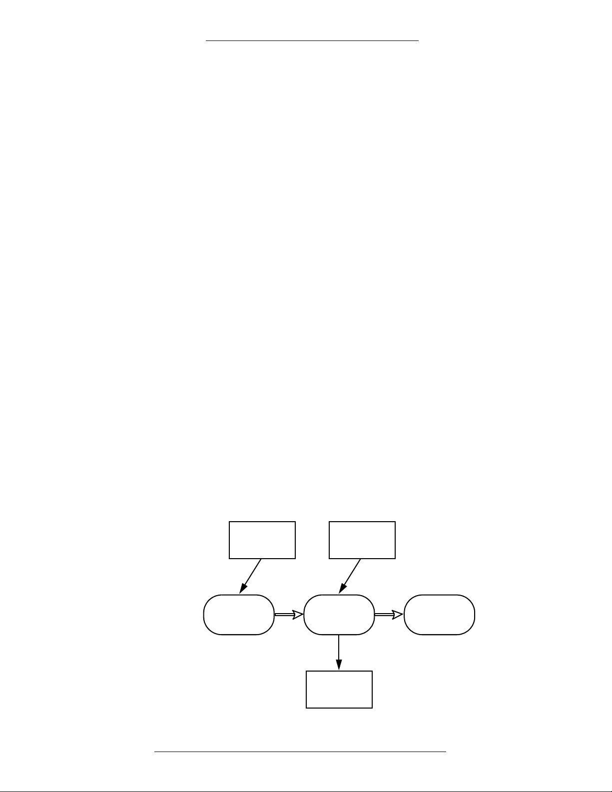
DVR
Configuration
AV Player
Configuration
Event
Actions
DVR
Equipment
NamespaceDatabase
However, you may want to specifically define the operation of a piece of equipment. For
example, you may have one Camera that is fixed, so you do not want to enable the “move”
functions for the operator when running AV Player. In this case you would specifically set up
and configure a named Camera. Any functions expressly defined for the named Camera will
override the global Camera information in the AV Switch configuration.
Similarly, the Camera configuration will define
global information about the Presets for the
Camera, including the number of the Presets that are to be generated in the namespace. For
example, if the Camera definition generates 20 Presets, then the 20 Presets will exist in the
namespace tagged with the namespace name. However, if you want to give a specific name
to the Presets, you would need to specifically set up and define each Preset in the CCTV/AV
Configuration window.
Namespace and Database
When you define the CCTV Server, AV Switch, and other items in the CCTV/AV
Configuration window (except for Dry Contacts), the software creates a database
table for each item, and will also create a valid entry for the AV Switch in the AV
Server namespace. If the system then uses the default settings for the DVR protocol,
as many entries are added to the namespace as there are default items, but no
database tables will be created for these items until one of the items has been
specifically created, configured, and saved. For example, if you specifically create a
Preset, a record will be created and it will contain information about the named
Preset. When you create the Preset, you will allocate the Preset a number that the
software will use to create the namespace name (OPC name) for the Preset. The
namespace entry will be updated from any information in the database when the
CCTV Server is next started.
Relationship Between the Namespace and Database
The following illustration summarizes how the various system activities relate to the
namespace and database.
1-8 24-10515-13 Rev. –
This document contains confidential and proprietary information of Johnson Controls, Inc.
© 2010 Johnson Controls, Inc.
Page 19

DVR Integration Option Introduction
DVR Naming Conventions
Where there is a large number of components a DVR system, it is helpful to name
them with a consistent naming convention. For example, a Camera may be assigned
a name that also includes the AV Switch name (OfficeCam1), or it may be named
with the location of the Camera (Floor 4), or the area of its view (West Car Park).
These names are added to the DVR database. Using meaningful names will help the
system operators.
The AV Server namespace names are assigned automatically, using the number
gned to the item when it is manually or automatically configured.
assi
Naming Items for the AV Server Namespace
Each of the items that you define specifically in the CCTV/AV Configuration
window (except for Dry Contacts) is automatically allocated an identifying name
that is recognized by the CCTV Server. The name comprises the number of the item
and a fixed description. In the case of Cameras and Monitors, the number is the
physical address that the equipment is wired to at the AV Switch; in the case of other
AV Switch elements, the address is a logical address that can be recognized by the
CCTV Server. The fixed description is assigned automatically by the DVR software
when the item number is added to the CCTV/AV Configuration window.
NOTE
The AV Server namespace for the CCTV Server is initialized from the
P2000 database each time the CCTV Server is started. If the CCTV Server
cannot find the P2000 database, then the namespace is initialized from a
local copy. However, the local copy will have been made when the P2000
database was last read, so it may not be up-to-date.
The item name is automatically tagged with an inherent name. For example, a Preset
is recognized by its AV Switch, Camera, and Preset name; Presets created for
different Cameras can have the same number but will have a different namespace
name.
When you create records in the CCTV/AV Configuration
a number for the address of the item that you are adding. Each number is prefixed by
one or two letters. The following table shows the prefix letters and the range of
numbers permitted for each item.
Namespace Item Parent Item Prefix Range
Switch Server AV 1 to 9999
Monitor Switch M 1 to 9999
window, you need to enter
Camera Switch C 1 to 9999
Camera Presets SwitchCamera Pr 1 to 9999
24-10515-13 Rev. – 1-9
This document contains confidential and proprietary information of Johnson Controls, Inc.
© 2010 Johnson Controls, Inc.
Page 20

Introduction DVR Integration Option
The number of items is determined by the DVR hardware and the protocol used. In
addition, if the system is configured with the CCTV advanced feature and a CCTV
Switch, the number of Cameras and Monitors is determined by the capacity of the
CCTV Switch.
The prefix letters for the item are automatically inserted by the CCTV/AV
Configuration window.
The number is selected by the user. The following rules must be followed:
AV Switches must be numbered consecutively starting from AV0001.
For Cameras and Monitors the number must match the hardware address at
the AV Switch. There is no automatic checking whether the number is
correct. Where a large number of Monitors and Cameras is installed it is
recommended that the installing engineer develops a plan for the addressing
process, so that the correct numbers can be entered into the CCTV/AV
Configuration window.
Additional recommendations are as follows:
Connect Cameras and Monitors to the low-numbered addresses at the
AV
Switch in order to keep the number of AV Server namespace entries as
small as possible.
For easier operations, define the most frequently used equipment with
numbers that will appear in the AV Player window, that is: AV0001 to
AV0006 for AV Switches, M0001 to M0020 for Monitors, andC0001 to
C0040 for Cameras.
NOTE
The CCTV Server system uses intrinsic addressing, so it is recommended
that you do not change the address of the items once they have been
configured. If you do, you may find that actions that use intrinsic
addressing (for example, OPCWrite event actions) refer to a different item.
Defining the Number of Namespace Items
When you create and configure items for the CCTV Server, you need to give each
item in the namespace a number. The range of numbers permitted is dependent on
the number of items configured for the namespace.
A feature of the software allows the namespace items to be configured
automatically. You can decide whether the total number of items in the namespace is
based on the default number of names defined by DVR protocol, or whether it is
based on a specific user-defined number.
Automatic configuration of the namespace items is useful for the initial software
setup. It allows you to have a working system after just configuring a CCTV Server
and an AV Switch with the DVR protocol defaults, and connecting the Cameras and
Monitors to a valid address at the AV Switch.
1-10 24-10515-13 Rev. –
This document contains confidential and proprietary information of Johnson Controls, Inc.
© 2010 Johnson Controls, Inc.
Page 21

Chapter
!
CAUTION
DVR configuration should be performed by a system engineer or a system
administrator. Although it is simple to use the DVR integration on a daily basis,
the system engineer will need some specific knowledge of the DVR equipment
in order to configure the hardware.
2
CONFIGURATION
DVR CONFIGURATION OVERVIEW
To operate your Johnson Controls® DVR system, the DVR integration must be set up and
configured to communicate with the system hardware. This setup is performed from the
CCTV/AV Configuration window.
The system hardware consists of the Digital Video Recorder (also called an “AV Switch”),
Dry Contacts, and Cameras. If integrated with the CCTV advanced feature, the system may
also include CCTV Switch and Monitors.
Communication with the system hardware is provided by the CCTV
The CCTV Server is OPC-compliant (OPC stands
further information relating to the OPC Interface Standard, see the OPC Foundation
Interface Specification.
The protocol used by the DVR system must be def
window. The configuration of the Cameras, Monitors, and Dry Contacts may be performed
automatically or customized to your particular requirements.
Configuration should progress
followed by the Cameras, Monitors, and Dry Contacts that are associated with it. After the
system is configured, you may return to a component and make changes if necessary.
in a logical sequence. First, configure the AV Switch,
for “OLE for Process Control”). For
ined in the CCTV/AV Configuration
Server and AV Server.
Using the CCTV/AV Configuration Window
The CCTV/AV Configuration window provides quick access to the component
configurations. All “root” items in the CCTV/AV Configuration “tree” are displayed
on the left side of the window. A “+” sign next to an item indicates that “branches”
exist beneath them. When you select a branch in the tree, the detailed settings and
values relating to that selection are listed on the right side of the windowpane.
You can add as many items to the CCTV/AV Configuration
24-10515-13 Rev. – 2-1
This document contains confidential and proprietary information of Johnson Controls, Inc.
© 2010 Johnson Controls, Inc.
window as you need.
Page 22
Configuration DVR Integration Option
After items have been added, you can edit them as desired.
The CCTV/AV Configuration
o access the CCTV/AV Configuration window:
T
1. From the P2000 Main menu, select Options>CCTV/A
2. If prompted, enter the password
window is accessed from the P2000 Main menu.
V>Configuration.
(Johnson Controls uses master as the
default setting). The CCTV/AV Configuration window opens.
T
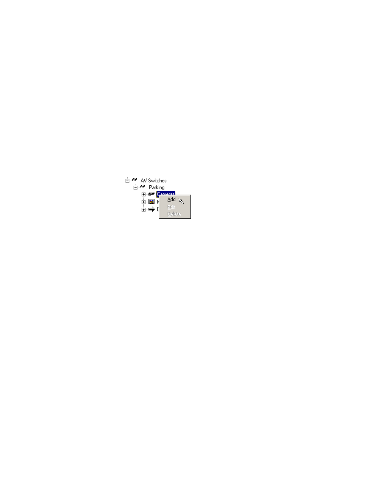
o add an item to the CCTV/AV Configuration window:
1. From the configuration tree, click the root
icon for the item you wish to add.
2. To access configuration windows, either click the Add button at the bottom
e window or right-click to access a shortcut button and select Add. The
of th
appropriate window appears.
3. Add the information according to the field definitions and click OK to return
to the CCTV/AV Configuration window. When windows offer several
configuration tabs, such as in the Edit AV Switch window, configure each tab
in turn, as applicable. You may not be able to access some tabs until a
minimum of information has been entered into the active tab.
4. When all settings have been entered, click OK to sav
e your settings and
return to the CCTV/AV Configuration window. Verify that the settings for the
new item are listed in the right side of the window.
5. Continue to add items in this manner unt
il all items and their related controls
have been configured.
T
o edit CCTV/AV configuration items:
1. From the configuration tree, right-click the item to
be configured and select
Edit (you can also select the item and click Edit from the shortcut button).
The Edit window appears.
2. Complete your changes and click OK
to save the settings.
3. Verify that the changes appear in the right side of the CCTV/AV
Configuration window
.
NOTE
Any changes will take effect only after the CCTV Server has been stopped
and restarted using Service Control. For instructions see “Starting and
Stopping Service Control” in the P2000 Software User Manual.
2-2 24-10515-13 Rev. –
This document contains confidential and proprietary information of Johnson Controls, Inc.
© 2010 Johnson Controls, Inc.
Page 23

DVR Integration Option Configuration
CONFIGURING DVR COMPONENTS
Configuration should progress in a logical sequence. First, configure the AV Switch,
followed by the Cameras, Monitors, and Dry Contacts that are associated with it. After the
system is configured, you may return to a component and make changes if necessary.
It is recommended that you use a naming convention to apply to DVR Components.
NOTE
If you are using NiceVision version 9.0, see “Nice” on page 4-16 before
proceeding.
To access the CCTV/AV Configuration window:
1. From the P2000 Main menu, select Options>CCTV/AV>Configuration.
2. If prompted, enter the password (Johnson Controls uses master as the
default setting) and click OK.
3. In the CCTV/AV Configuration window, proceed with the actions you want
to perform.
NOTE
For any DVR configuration changes to take effect, the CCTV Server must
be stopped and restarted using P2000 Service Control. This should be
done at the completion of your configuration session.
A fully configured system will display the configured items in the left windowpane,
and information about the item in focus in the right windowpane.
General Configuration Notes
The following notes apply to all protocols:
It is recommended that you develop a naming convention to apply to
Switches, Cameras, Monitors, and Dry Contacts before programming the
AV
software.
The first 12 characters of named AV Switches, Monitors, and Cameras will
appear in the AV Player window (the full name for the item is displayed when
the cursor hovers over the button or the button is selected). It is therefore
useful to use names that have the first 12 characters unique and meaningful.
Changes to the configuration settings will not take effect until the CCTV
Server has been restarted using the P2000 Service Control. This means that if
it is currently running, you will need to stop it and then restart it.
Provided the CCTV Server and AV Switch are configured, you can use the
equipment’s default settings.
24-10515-13 Rev. – 2-3
This document contains confidential and proprietary information of Johnson Controls, Inc.
© 2010 Johnson Controls, Inc.
Page 24
Configuration DVR Integration Option
!
CAUTION
In addition to the above notes, some protocols require additional steps or
particular configuration settings. Chapter 4: Protocol Integration contains
some of that information, as available at the time of this publication. It is
recommended that you refer to the DVR’s manufacturer for further
documentation and guidance on protocol-specific settings.
The installation and operation of the DVR equipment must be done in
accordance with the manufacturer's instructions.
The DVR Equipment must be time-synchronized with the P2000 server.
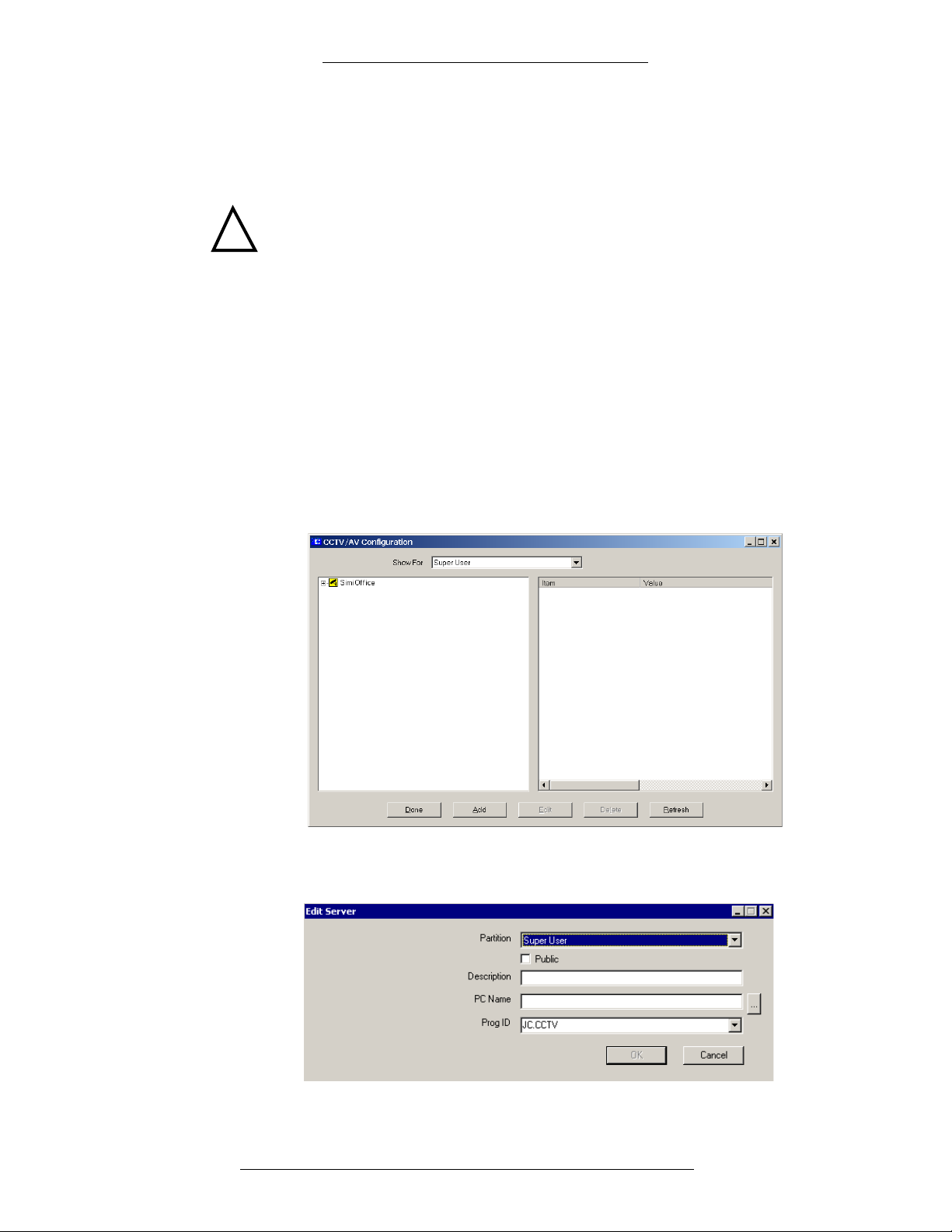
CCTV Server
The CCTV Server must be configured to establish communication and control.
o add and configure a CCTV Server for DVR:
T
1. Open the CCTV/AV Configuration window.
2. In the CCTV/AV Configuration window, right-click the icon for the CCTV
Server and click Ad
d.
3. In the Edit Server window, fill in the information for each field according to
the “Edit Server Field Definitions” below.
4. Click OK to save the new information.
2-4 24-10515-13 Rev. –
This document contains confidential and proprietary information of Johnson Controls, Inc.
© 2010 Johnson Controls, Inc.
Page 25

DVR Integration Option Configuration
Edit Server Field Definitions
Partition – If partitioning is available, select the partition that will have access to this
CCTV Server information.
Public – If partitioning is available, select this check box to allow all partitions to see
this CCTV Server.
NOTE
The CCTV Server must be set to Public if you wish to assign a CCTV
Switch or AV Switch in a different partition.
Description – This is a user-defined description of up to 30 characters to describe the
CCTV Server.
PC Name – Enter the name of the PC on which the CCTV Server resides. This will
usually be the name of the P2000 server on which you are operating. You can also
search for the name using the browse button.
Prog ID – An installed CCTV Server is associated with a Program ID. Select the
Program ID for the CCTV Server. The default Program ID for the CCTV Server is
JC.CCTV. Sub versions may be released from time to time (numbered consecutively
starting with JC.CCTV1), but using JC.CCTV ensures that you use the latest
version.
AV Switches
An AV Switch receives video inputs from Cameras and outputs the data to video
outputs. Each Switch operates using the manufacturer’s protocol; the functionality
of the AV Switch is largely determined by the protocol provided and the capacity of
the equipment connected to the AV Switch. For a list of currently supported
protocols, refer to
Creating and Configuring AV Switches
A DVR (Digital Video Recorder), also called an AV Switch, is connected to a PC
with a CCTV Server running on it. The AV Switch will have a variety of equipment
connected to it, including Monitors, Cameras, and Dry Contacts. Equipment
connected to an AV Switch is presumed to be compatible with that specific
Switch. A CCTV Server system may include a number of separately connected
AV
AV Switches, and each may use a different protocol. However, only one version of
each protocol can be used within a P2000 system.
To establish communication and control, each AV Switch installed in your system
must be set up and configured in the CCTV/AV Configuration window. At the
highest level, this window displays the CCTV Server. To display icons for the AV
Switches, expand the CCTV Server’s entry.
“Supported Protocols” on page 1-4.
24-10515-13 Rev. – 2-5
This document contains confidential and proprietary information of Johnson Controls, Inc.
© 2010 Johnson Controls, Inc.
Page 26
Configuration DVR Integration Option
To add an AV Switch and configure alarm options:
1. Open the CCTV/AV Configuration window.
2. Select the root A
V Switches icon and click Add.
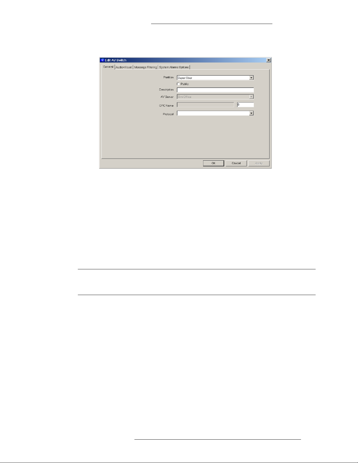
3. The Edit AV Switch window opens with the General tab active.
Fill in the information under the following tabs:
General
Audio-Visual
Message Filtering
For reference use the section “Edit AV Switch Field Definitions” on
page 2-8.
In each tab, click Appl
y to save your changes.
2-6 24-10515-13 Rev. –
This document contains confidential and proprietary information of Johnson Controls, Inc.
© 2010 Johnson Controls, Inc.
Page 27

DVR Integration Option Configuration
Example of user
defined categories
4. Click the System Alarm Options tab. It displays all alarm categories
assigned to this AV switch.
All alarms originating at the AV switch (A
V alarms) must belong to at least
one Alarm Category. The default category for a new AV switch is “P2000.”
5. Click the Add button to assign system alarms to one or more Alarm
Categories. (Click Delete if you want to delete a highlighted category from
the list of Alarm Categories assigned to this alarm.)
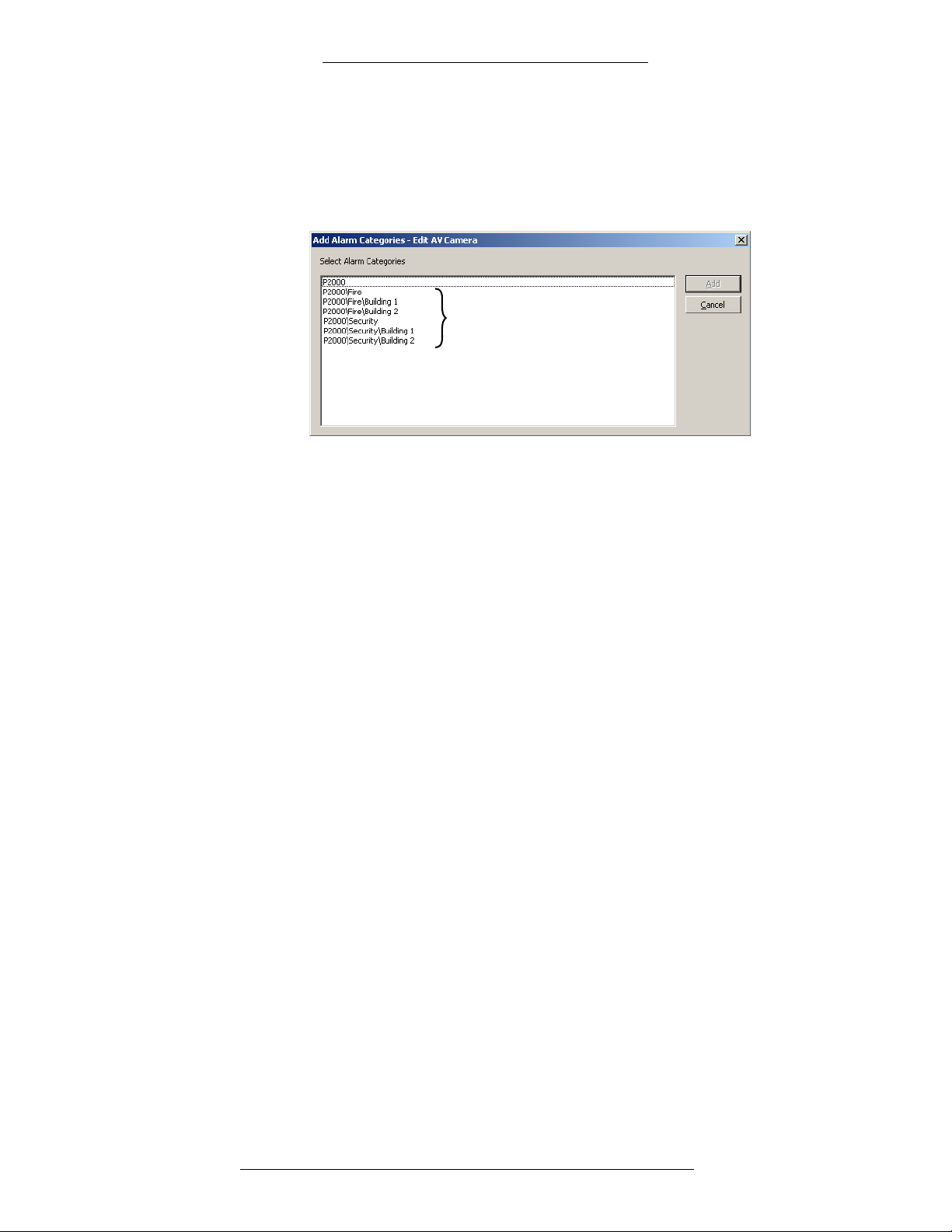
6. The Add Alarm Categories window opens. It lists the default “P2000”
category and all user
-defined categories. (If you are using Enterprise
configuration, the Alarm Categories defined for all P2000 sites within an
Enterprise system will be listed.) Select one or more categories and click
Add.
7. To edit alarm options for an Alarm Category, highlight the alarm option the
Edit AV Switch window and click Edit. You can select and edit more than
one category at a time.
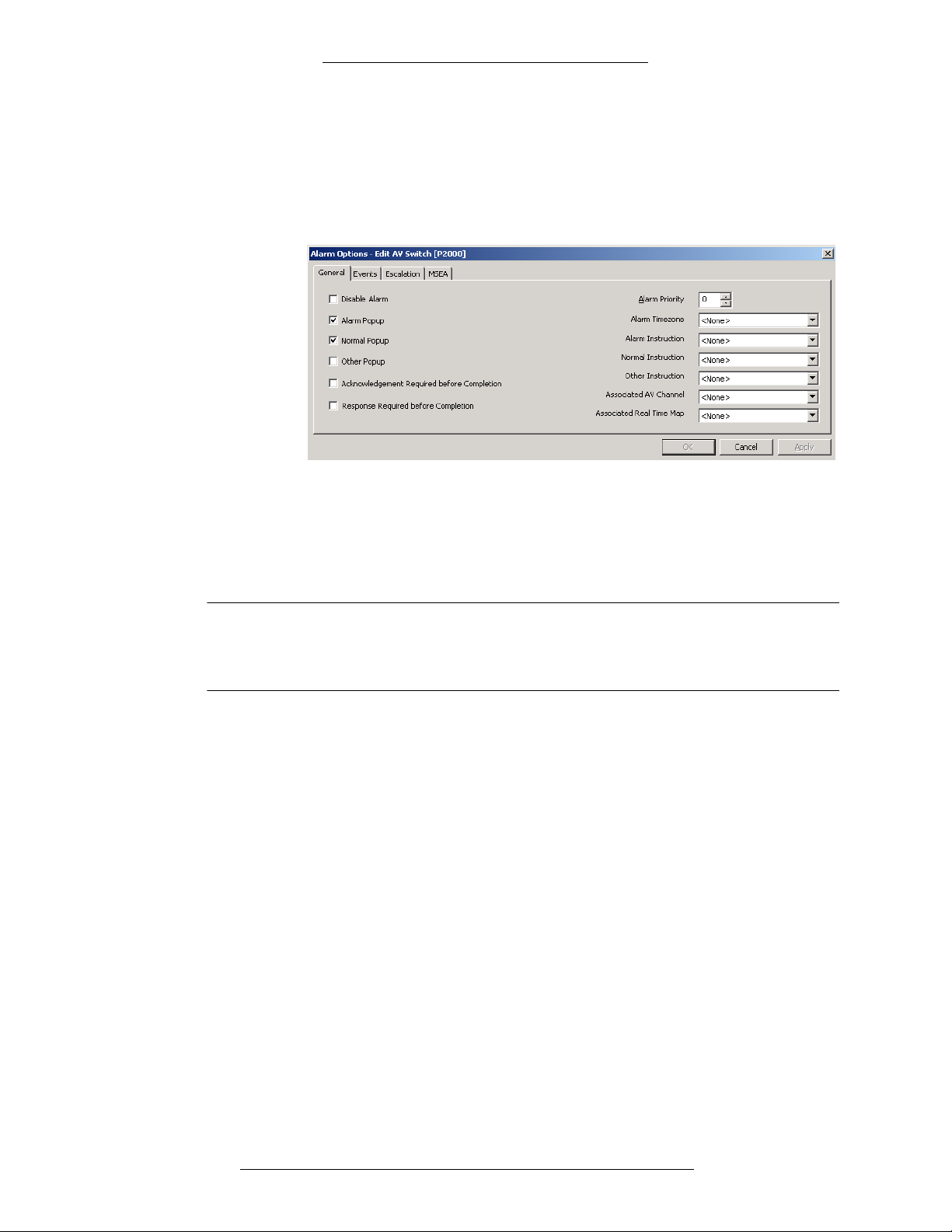
8. The Alarm Options window opens with the General ta
b active.
Edit the options under the following tabs:
24-10515-13 Rev. – 2-7
This document contains confidential and proprietary information of Johnson Controls, Inc.
© 2010 Johnson Controls, Inc.
General
Events
Page 28
Configuration DVR Integration Option
Escalation
MSEA
For reference use the section “Alarm Options Field Definitions” on
page 2-26.
Click OK to save your changes and return to the Alarm Categories window.
9. Repeat steps 6 - 8 to configure all Alarm Categories assigned to this AV
switch.
10. Click OK to save your changes and close the Edit AV Switch window.
11. Click Done to close the CCTV/AV Configuration window.
NOTE
For any DVR configuration changes to take effect, the CCTV Server must
be stopped and restarted using P2000 Service Control. This should be
done at the completion of your configuration session.
When a new AV Switch is created, a corresponding icon is displayed under the root
AV Switches icon in the CCTV/AV Configuration window. The icons for all AV
Switch components are listed under it.
Edit AV Switch Field Definitions
The Edit AV Switch window opens at with the General tab active. You must enter
information in all Edit AV Switch tabs to complete your configuration of the AV
Switch.
If you enable a function that is not available for the particular protocol, then the
operator’s action will have no effect. The system does not check whether the
functions selected at the AV Switch are compatible with the functionality of the
equipment.
2-8 24-10515-13 Rev. –
This document contains confidential and proprietary information of Johnson Controls, Inc.
© 2010 Johnson Controls, Inc.
Page 29
DVR Integration Option Configuration
General Tab
Partition – If partitioning is available, select the partition that will have access to this
AV Switch information.
Public – If
partitioning is available, select this check box to allow all partitions to see
this AV Switch.
Description –
This is the user-defined name of the AV Switch. The name will be
displayed in the AV Player window.
AV Server –
This is the name of the CCTV Server that resides on the PC that the AV
Switch is physically connected to. This name is automatically entered by the
software.
NOTE
When used for the DVR operation, the CCTV Server is also referred to as
the AV Server.
OPC Name – In the text box to the right, enter the number of the AV Switch. The
number is automatically appended to the prefix letter and added to the OPC Name
field. For further information about namespace names and item numbers, see
“Naming Items for the AV Server Namespace” on page 1-9.
Protocol –
Switch.
Audio-Visual Tab
Select the DVR protocol to be used with this make and model of the AV
There are two versions of the AV tab, depending on the protocol used by the AV
Switch. This tab is not available for the Loronix protocol.
24-10515-13 Rev. – 2-9
This document contains confidential and proprietary information of Johnson Controls, Inc.
© 2010 Johnson Controls, Inc.
Page 30
Configuration DVR Integration Option
Audio-Visual Tab for Protocols Other Than SmartSight
Streaming Server IP Address – IP address of the Streaming Server (usually the IP
address of the AV Switch). The Streaming Server allows transmission and viewing
of audio and video.
Data Server IP Address –
IP address of the Data Server (usually the IP address of the
AV Switch). The Data Server is a database server that maintains all necessary
information for operating DVR functions including administration, video clip
logging, etc. In addition, it handles all video retrieval requests.
Storage Server IP Address –
IP address of Storage Server (usually the IP address of
the AV Switch). This is an archive server that typically has a number of tape
libraries.
Username
Password –
Confirm Password –
– Login user name needed to access remote DVR systems.
Login password needed to access remote DVR systems.
Re-enter login password needed to access remote DVR systems.
Server Name – Name of the server computer that is responsible for manipulating a
deo matrix switch. This is the network ID computer name of the AV Switch that
vi
communicates with the CCTV Switch.
IP Address –
IP address of the video matrix switch server. This is the IP address of
the AV Switch that communicates with the CCTV Switch.
The COM port of the AV Switch that is physically connected to the CCTV
Port –
Switch. Note that the software will check with the CCTV Server to establish
whether there is a conflict in port usage, but will not check with any other equipment
that may be running.
2-10 24-10515-13 Rev. –
This document contains confidential and proprietary information of Johnson Controls, Inc.
© 2010 Johnson Controls, Inc.
Page 31

DVR Integration Option Configuration
Audio-Visual Tab for the SmartSight Protocol
Primary Directory Server IP Address – Use this address to configure multiple
Directory Servers for failover. By default, this will be the first address used to
establish connection.
Secondary Directory Server IP Address
– Use this address to configure multiple
Directory Servers for failover. By default, this will be the second address used to
establish connection.
Tetriary Directory Server IP Address
– Use this address to configure multiple
Directory Servers for failover. By default, this will be the third address used to
establish connection.
Use Subnet 2 –
Define the subnet if the P2000 workstations require an IP address
different from the one used by the P2000 server to connect to the same SmartSight
Directory Server.
Username
Password –
Confirm Password –
– Login user name needed to access remote DVR systems.
Login password needed to access remote DVR systems.
Re-enter login password needed to access remote DVR systems.
24-10515-13 Rev. – 2-11
This document contains confidential and proprietary information of Johnson Controls, Inc.
© 2010 Johnson Controls, Inc.
Page 32

Configuration DVR Integration Option
Message Filtering Tab
Process AV Messages
Motion Detection – From the drop-down list select the timezone durin
g which the
Motion Detection AV messages will be processed.
Dry Contact – From the drop-down list select the timezone durin
g which the Dry
Contact AV messages will be processed.
Video Loss –
From the drop-down list select the timezone during which the Video
Loss AV messages will be processed.
Behavior –
From the drop-down list select the timezone during which the Behavior
AV messages will be processed.
AV Messages Debounce Time
Motion Detection – If a time between two consecutive mo
tion detection alarms
coming from the same source (camera) is less than the defined value, the second
alarm will not be added to P2000 alarm queue.
Behavior –
If a time between two consecutive behavior alarms coming from the
same source (camera) is less than the defined value, the second alarm will not be
added to P2000 alarm queue.
Generate AV Alarm
– From the drop-down list select which messages will be transmitted to a
Mode
mapped camera as P2000 alarms. Select <Send none> to disable transmission of all
messages. Select <Send all> to allow transmission of all messages that pass the
Timezone criteria. Select <Send filtered> to allow transmission of messages that
pass the Timezone criteria and the Message Filter Group criteria.
2-12 24-10515-13 Rev. –
This document contains confidential and proprietary information of Johnson Controls, Inc.
© 2010 Johnson Controls, Inc.
Page 33

DVR Integration Option Configuration
NOTE
Mode settings only apply to alarms that are generated for input points
mapped to cameras in the input to Camera application. “Camera Send
Alarm” event actions will ignore the Mode option selected here.
Timezone – From the drop-down list select the time zone during which messages that
pass the Message Filter Group criteria will be transmitted to a mapped camera as
P2000 alarms. Select <Always Enabled> if you wish to send messages at all times.
Message Filter Group – From the
drop-down list select the Message Filter Group that
defines which of the messages that pass the Timezone criteria will be transmitted to
a mapped camera as P2000 alarms. Select <None> if you wish to transmit all
messages.
System Alarm Options Tab
Select Alarm Categories
– Click this button to open the Alarm Options window and edit the alarm
Edit
options for a highlighted Alarm Category. See “Alarm Options Field Definitions” on
page 2-26 for more information.
Add – Click this
button to open the Add Alarm Categories window and assign this
alarm to an additional Alarm Category.
Delete –
Click this button to delete a highlighted Alarm Category from the list of
categories assigned to this alarm.
24-10515-13 Rev. – 2-13
This document contains confidential and proprietary information of Johnson Controls, Inc.
© 2010 Johnson Controls, Inc.
Page 34

Configuration DVR Integration Option
Cameras
Cameras are physically connected to the AV Switch and are recognized by their
physical address.
Creating and Configuring Cameras
The Cameras need to be defined manually. It is recommended that you name them in
a consistent manner for easier use. Refer to “DVR Naming Conventions” on
page 1-9 for more information.
o add a named Camera and configure alarm options:
T
1. In the CCTV/AV Configuration window, expand the A
V Switches entry.
Click the + by the icon for the AV Switch to which the Camera is connected.
This will display all the items associated with that particular Switch.
2. Right-click the Cameras icon and click Add.
3. The Edit AV Camera window opens with the General ta
b active. (If the
window is minimized, click on the Windows taskbar to restore it.)
Edit the options under the following tabs:
General
Controls
For reference see “Edit AV Camera Field Definitions” on pag
In each tab, click Appl
2-14 24-10515-13 Rev. –
y to save your changes.
This document contains confidential and proprietary information of Johnson Controls, Inc.
e 2-16.
© 2010 Johnson Controls, Inc.
Page 35

DVR Integration Option Configuration
4. Configure each alarm type (motion, behavior, or video loss). Start with
clicking the appropriate alarm tab in the Edit AV Camera window:
Motion Alarm Options
Behavior Alarm Options
Video Loss Alarm Options
5. The Select Alarm Categories list
displayed under the selected alarm tab
contains all Alarm Categories to which this type of alarm has been assigned.
The “P2000” Alarm Category is listed by default.
6. To add more categories, click the Add button.
24-10515-13 Rev. – 2-15
This document contains confidential and proprietary information of Johnson Controls, Inc.
© 2010 Johnson Controls, Inc.
Page 36
Configuration DVR Integration Option
Example of user
defined categories
7. The Add Alarm Categories window opens. It lists the default “P2000”
category and all user-defined categories. (If you are using Enterprise
configuration, the Alarm Categories defined for all P2000 sites within an
Enterprise system will be listed.) Select one or more categories and click
Add.
8. To delete a category from the list of Alarm Categories assigned to this alarm,
highlight it in the list and click Delete.
9. To edit alarm options, in the Edit A
V Camera window highlight a category
and click Edit.You can select and edit more than one category at a time.
10. The Alarm Options window opens with the General ta
b active.
Edit the options under the following tabs:
General
Events
Escalation
MSEA
For reference use the section “Alarm Options Field Definitions” on
page 2-26.
Click OK to save your changes
11. Repeat steps 9-10 to configure all Alarm Categories assigned
type. Click App
ly to save your changes.
and return to the Alarm Categories window.
to this alarm
12. Repeat steps 4-11 until you have configured all three alarm types (motion,
behavior, and video loss alarms).
13. To verify the camera’s functionalit
14. Click OK to close the Edit A
y, click the AV Camera Test tab.
V Camera window.
2-16 24-10515-13 Rev. –
Edit AV Camera Field Definitions
The Edit AV Camera window opens at the General tab. (If the window is
minimized, click on the Windows taskbar to restore it.) You must enter information
in all Edit AV Camera tabs to complete your configuration of the Camera.
This document contains confidential and proprietary information of Johnson Controls, Inc.
© 2010 Johnson Controls, Inc.
Page 37

DVR Integration Option Configuration
General Tab
Partition – If partitioning is available, select the partition that will have access to this
Camera’s information.
Public – If
partitioning is available, select this check box to allow all partitions to see
this Camera.
Description –
This is the user-defined name of the Camera. The name will be
displayed in the AV Player window.
NOTE
For some protocols, the user-defined name must match the name of the
camera as defined in the DVR. See Chapter 4: Protocol Integration for
details.
AV Switch – This is the name of the AV Switch that the Camera is physically
connected to. The AV Switch name is automatically entered into this field.
OPC Name –
number is automatically appended to the prefix letter and added to the OPC Name
field. For further information about namespace names and item numbers, see
“Naming Items for the AV Server Namespace” on page 1-9.
In the text box to the right, enter the number of the Camera. The
24-10515-13 Rev. – 2-17
This document contains confidential and proprietary information of Johnson Controls, Inc.
© 2010 Johnson Controls, Inc.
Page 38

Configuration DVR Integration Option
Controls Tab
If the majority of your Cameras are of one type (for example, fixed), it is
recommended that you select the Camera functions that apply to the majority of the
equipment. You would then be able to specifically configure those Cameras that
have different capabilities.
General String – This string consists of up to 50 characters that may be displayed at
the Monitor when the Camera is operating from the AV Player window (provided
the protocol allows it). It could be the name of the Camera or a description of the
location of the Camera. This is an optional field.
If available, select the check box to enable Tilt for this Camera.
Tilt –
If available, select the check box to enable Pan for this Camera.
Pan –
Zoom –
Focus
Iris –
Iris Automatic – If
If available, select the check box to enable Zoom for this Camera.
– If available, select the check box to enable Focus for this Camera.
If available, select the check box to enable Iris for this Camera.
available, select the check box to enable the Automatic Iris for
this Camera.
Wiper –
If available, select the check box to enable Wiper for this Camera.
Washer – If available, select the check box to enable Washer for this Camera.
Light – If available, select th
Status –
Lens Speed –
If available, select the check box to enable Status for this Camera.
This is the speed of the lens. Refer to the manufacturer’s instructions.
e check box to enable the Light for this Camera.
Lens Speed Max – T
his is the maximum speed of the lens. Refer to the
manufacturer’s instructions.
2-18 24-10515-13 Rev. –
This document contains confidential and proprietary information of Johnson Controls, Inc.
© 2010 Johnson Controls, Inc.
Page 39

DVR Integration Option Configuration
Tabs for Alarm Options
These three tabs (Motion Alarm Options, Behavior Alarm Options, Video Loss
Alarm Options) look the same. They list the Alarm Categories to which alarms of a
particular type have been assigned, and provide access to the Add Alarm Categories
and Alarm Options windows.
Alarm debounce time - Enter a minimum delay time in milliseconds. When two
consecutive alarms of the same type and coming from the same camera occur within
the specified delay time, the second alarm will not be added to the alarm queue. This
feature is available for motion and behavior alarms.
Edit – Click this button to open
the Alarm Options window for one or more
highlighted Alarm Categories. See “Alarm Options Field Definitions” on page 2-26
for more information.
Click this button to open the Add Alarm Categories window.
Add –
Delete – Click this button to delete a high
lighted Alarm Category.
AV Ca mer a Te st Ta b
This tab provides the Launch AVPlayer button. Click this button to display live
image and, depending on the hardware you are using, to test supported functions.
24-10515-13 Rev. – 2-19
This document contains confidential and proprietary information of Johnson Controls, Inc.
© 2010 Johnson Controls, Inc.
Page 40

Configuration DVR Integration Option
Camera Presets
A Preset Camera position is a user-defined position which may include pan, tilt,
zoom, and focus adjustments. Numbered Presets will be defined as part of the AV
Switch or Camera definition; specifically named Camera Presets can be defined in
the CCTV/AV Configuration window. If the Preset is a named item, the name will
be displayed in the AV Player window. Named and numbered Camera Presets can
be used from the PTZ tab of the AV Player window, provided the equipment is
available and is able to perform the required functions.
T
o add a named Camera Preset:
1. In the CCTV/AV Configuration window, click the AV
S w i t c h icon that the
Camera is associated with. Click the + to open the items for the AV Switch.
2. Click the + to open the items for the Ca
3. Click the Pr
esets icon and click Add. The Edit AV Preset window opens.
mera.
4. If partitioning is available, select the Partition that will have access to this
Preset information.
5. If partitioning is available, select the Publ
ic check box to allow all partitions
to see this Preset.
6. In the De
scription field, enter the user-defined name of the Preset. The name
will be displayed in the AV Player window.
7. The A
8. In the OPC Nam
V Camera field displays the name of the Camera that the Preset is phys-
ically connected to. The Camera name is automatically entered into
e field, enter the number of the Preset. The number is
this field.
automatically appended to the prefix letter and added to the OPC Name field.
For further information about namespace names and item numbers, see
“Naming Items for the AV Server Namespace” on page 1-9.
9. Click OK t
o save the settings.
Monitors
Monitors are physically connected to a CCTV Switch which is controlled by the AV
Switch. They are recognized by their physical address.
2-20 24-10515-13 Rev. –
This document contains confidential and proprietary information of Johnson Controls, Inc.
© 2010 Johnson Controls, Inc.
Page 41

DVR Integration Option Configuration
Creating and Configuring Monitors
The Monitors connected to the AV Switch can be defined automatically. However,
defining individual Monitors simplifies the day to day operation of the system. It is
recommended that when the system is proven to perform correctly, the Monitors to
be used are named for easier use. Refer to “DVR Naming Conventions” on page 1-9
for more information.
o add a named Monitor:
T
1. In the CCTV/AV Configuration window, expand the A
V Switches entry.
Click the + by the icon for the AV Switch to which the Monitor is connected.
This will display all the items associated with that particular Switch.
2. Right-click the Monitors icon and click Add. The Edit AV Monitor window
opens. (For Genetec protocol Monitor ID and Pane Number fields are also
present).
3. Fill in the information for each field according to the “Edit AV Monitor Field
Definitions” below.
4. Click OK to close the window
24-10515-13 Rev. – 2-21
This document contains confidential and proprietary information of Johnson Controls, Inc.
© 2010 Johnson Controls, Inc.
.
Page 42

Configuration DVR Integration Option
Edit AV Monitor Field Definitions
Partition – If partitioning is available, select the partition that will have access to this
Monitor’s information.
Public – If partitioning is available, select this check box to allow all partitions to see
this Monitor.
Description – The name of the monitor as defined by the user. This name will be
displayed in the AV Player window.
AV Switch – The name of the AV Switch that the Monitor is physically connected to.
The AV Switch name entered into this field automatically.
OPC Name – In the text box to the right, enter the number of the Monitor. The
number is automatically appended to the prefix letter and added to the OPC Name
field. For further information about namespace names and item numbers, see
“Naming Items for the AV Server Namespace” on page 1-9.
General String – Specify a user string that will be displayed when AV Player is
running.
Decoder IP Address – Currently used with Nice 10.5 only. Specify the IP address of
the video decoder used to drive the monitor.
Monitor ID – Currently used with Genetec only. Enter the Genetec monitor ID value.
Pane Number – Currently used with Genetec only. Specify the pane location number.
This number identifies the location on a monitor where the camera video will be
displayed. If the pane value is 0, the system will display the video in the first empty
pane on the monitor.
Dry Contact
Dry Contacts are two-state (open/closed) input points physically connected to a
CCTV Switch and recognized by their physical address.
The Dry Contacts need to be defined manually. It is recommended that you name
them in a consistent manner for easier use. Refer to
page 1-9 for more information.
To add a named Dry Contact and configure alarm options:
1. In the CCTV/AV Configuration window, expand the AV Switches entry.
Click the + by the icon for the AV Switch to which the Dry Contact is
connected. This will display all the items associated with that particular
Switch.
“DVR Naming Conventions” on
2-22 24-10515-13 Rev. –
This document contains confidential and proprietary information of Johnson Controls, Inc.
© 2010 Johnson Controls, Inc.
Page 43

DVR Integration Option Configuration
2. Right-click the Dry Contact icon and click Add.
3. The Edit AV Dry Contact window opens with the General tab acti
ve.
Fill in the information under this tab according to the “Edit AV Dry Contact
Field Definitions” on page 2-25.
Click App
ly to save your changes.
4. Click the Alarm Options tab. It displays all alarm categories assigned to this
dry contact.
24-10515-13 Rev. – 2-23
This document contains confidential and proprietary information of Johnson Controls, Inc.
© 2010 Johnson Controls, Inc.
Page 44

Configuration DVR Integration Option
Example of user
defined categories
The Select Alarm Categories list contains all Alarm Categories to which this
type of alarm has been assigned. The “P2000” Alarm Category is listed by
default.
5. Click the Add button to assign system alarms to one or more Alarm
Categories. (Click Delete if you want to delete a highlighted category from
the list of Alarm Categories assigned to this alarm.)
6. The Add Alarm Categories window opens. It lists the default “P2000”
category and all user
-defined categories. (If you are using Enterprise
configuration, the Alarm Categories defined for all P2000 sites within an
Enterprise system will be listed.) Select one or more categories and click
Add.
2-24 24-10515-13 Rev. –
7. To edit alarm options for an Alarm Category, highlight it the Edit AV Dry
Contact window and click Edit. You can select and edit more than one
category at a time.
8. The Alarm Options window opens with the General ta
b active.
9. Edit the options under the following tabs:
General
Events
Escalation
MSEA
This document contains confidential and proprietary information of Johnson Controls, Inc.
© 2010 Johnson Controls, Inc.
Page 45

DVR Integration Option Configuration
For reference use the section “Alarm Options Field Definitions” on
page 2-26.
Click OK to save your changes
and return to the Alarm Categories window.
10. Repeat steps 7-9 to configure all Alarm Categories assigned to this dry
contact.
11. Click OK to save your changes
12. Click Done to close the CCTV/A
and close the Edit AV Dry Contact window.
V Configuration window.
Edit AV Dry Contact Field Definitions
The Edit AV Dry Contact window opens at the General tab. You must enter
information in both Edit AV Dry Contact tabs to complete your configuration of the
Dry Contact.
General Tab
24-10515-13 Rev. – 2-25
This document contains confidential and proprietary information of Johnson Controls, Inc.
© 2010 Johnson Controls, Inc.
Page 46

Configuration DVR Integration Option
Partition – If partitioning is available, select the partition that will have access to this
Dry Contact’s information.
Public – If partitioning is available, select this check box to allow all partitions to see
this Dry Contact.
Description – This is the user-defined name of the Dry Contact. The name will be
displayed in the AV Player window.
AV Switch – This is the name of the AV Switch that the Dry Contact is physically
connected to. The AV Switch name is automatically entered into this field.
Number – In the text box to the right, enter the number of the Dry Contact.
Alarm Options for DVR Components
To configure alarm options for an alarm generated by an AV switch, AV camera, or
AV Dry Contact, use the Alarm Options window.
Each AV alarm belongs to one or more Alarm Categories. You can configure
different alarm options for each Alarm Category to which the alarm belongs. These
different configurations can then be used with the Alarm Filter and Escalation
features of P2000 to design a system in which dynamic alarm routing allows for
effective use of the operator’s time.
For more information on Alarm Categories, Alarm Filter, and Escalation, refer to the
P2000 Software User Manual.
Alarm Options Field Definitions
The Alarm Options window will display the following in the title bar: “Alarm
Option,” the name of the window from which it was accessed, and the Alarm
Category.
For example:
If you are editing the alarm options for more than one category at a time, the Alarm
Category will be displayed as [*], for example:
2-26 24-10515-13 Rev. –
This document contains confidential and proprietary information of Johnson Controls, Inc.
© 2010 Johnson Controls, Inc.
Page 47

DVR Integration Option Configuration
General Tab
Disable Alarm – Leave this check box un-selected for the alarm to be added to the
alarm queue and displayed in the alarm monitoring window to notify the operator of
its activation. Selecting this check box will disable this alarm. Enabling/disabling of
the alarm is specific to a particular Alarm Category. For example, you can enable the
alarm for a user-defined “Warehouse” category and disable the same alarm for a
user-defined “Security” category.
NOTE
Before you assign instruction text to the various popups, you must first
create instruction text. For more information, refer to the P2000 Software
User Manual.
Alarm Popup – When you enable Alarm Popup for an alarm, the Alarm Monitor will
pop up at the front of the screen when the sending item is in the alarm state.
Normal Popup – When you enable Alarm Popup for an alarm, the Alarm Monitor
will pop up at the front of the screen when the sending item is in the normal state.
Other Popup – When you enable Alarm Popup for an alarm, the Alarm Monitor will
pop up at the front of the screen when the sending item is in the state other than
“alarm” or “normal.”
Acknowledgement Required before Completion – Select this check box to require
acknowledgement of this alarm before its completion.
Response Required before Completion – Select this check box to require response to
this alarm before its completion.
Alarm Priority – Enter a value from 0 to 255. Zero equals the highest priority. This is
the order in which the alarm message will be placed in the alarm queue. If alarm
messages have the same alarm priority, the date and time determine which alarm is
positioned higher in the queue.
24-10515-13 Rev. – 2-27
This document contains confidential and proprietary information of Johnson Controls, Inc.
© 2010 Johnson Controls, Inc.
Page 48

Configuration DVR Integration Option
Alarm Timezone – If you want the item to generate alarms only at certain time of the
day, select from the drop-down list the time zone during which the item activation
will be reported as an alarm in the Alarm Monitor window. If you select <none>,
item activation at any time will always result in generating an alarm.
Alarm Instruction – Alarm Instruction selected in the drop-down list will be
displayed in the Alarm Response window when the sending item is in the alarm
state.
Normal Instruction – Alarm Instruction selected in the drop-down list will be
displayed in the Alarm Response window when the sending item is in the normal
state.
Other Instruction – Alarm Instruction selected in the drop-down list will be displayed
in the Alarm Response window when the sending item is in the state other than
“alarm” or “normal.”
Associated AV Channel – Select the camera to be associated with this alarm. If
applicable, this selection will override the selection made in the Input to camera
mapping window.
Associated Real Time Map – Select the Real Time Map to be associated with this
alarm. If applicable, this selection will override the default behavior of the Real Time
Map containing the item for the alarm. That is, when you click the Map button in the
Alarm Monitor, the associated Real Time Map will be displayed, even if it is
different from the Real Time Map containing the alarm item.
Events Tab
Event 1-4 – You can define up to four events that can be triggered from the Alarm
Monitor window whenever the alarm occurs and is entered into the alarm queue. To
define an event, enter a descriptive name and select a previously configured Event
from the associated drop-down list.
2-28 24-10515-13 Rev. –
This document contains confidential and proprietary information of Johnson Controls, Inc.
© 2010 Johnson Controls, Inc.
Page 49
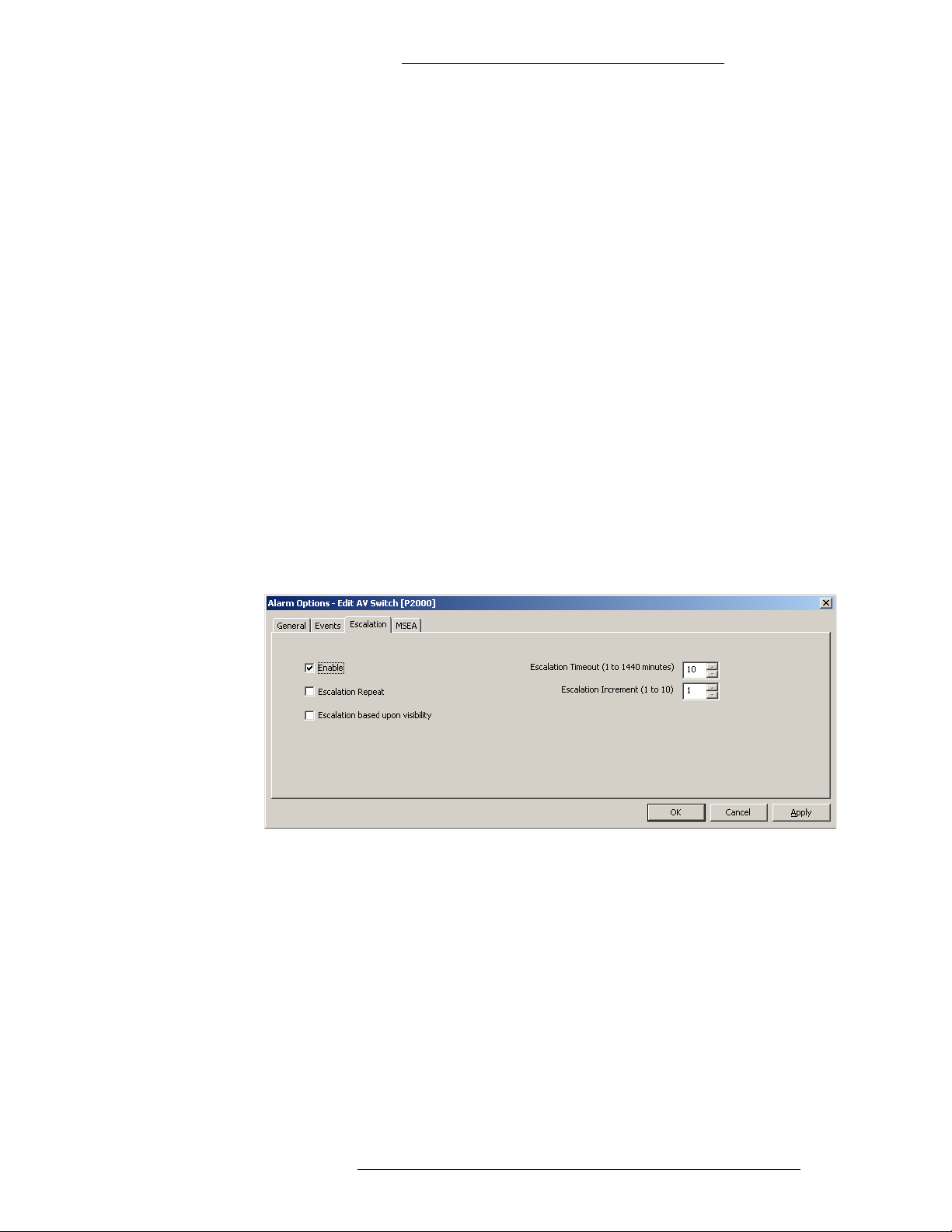
DVR Integration Option Configuration
Escalation Tab
The alarm escalation function constantly monitors all generated alarms that have
their escalation options enabled. Escalation level value range is from 0 to 10,
0 indicates a non-escalated alarm.
where
The alarm escalation feature provides for two different conditions when an alarm
may be escalated:
If an alarm is generated for a specific alarm category and there are currently
no operators logged into the P2000 that have privileges to receive alarms for
that category.
If an alarm is generated and remains pending for the configured escalation
timeout period.
If either of these conditions occurs, that alarm will be regenerated with an elevated
escalation level. The escalation level will be incremented by the configured
escalation increment value. This process may be repeated multiple times until a high
enough escalation level is reached that matches the privileges of a currently logged
in operator. If no operators are logged into the P2000, the alarm will be regenerated
until the maximum escalation level is reached, and then no further action will be
taken.
After an escalated alarm has been completed, the next occurrence of that alarm is
created with no escalation level.
Enable – Select this check box to enable alarm escalation.
Escalation Repeat – Select this check box to allow for escalation to occur more than
once for the alarm. For example, if the Escalation Timeout is set to 30 minutes, and
the Escalation Increment is set to 2, every half an hour the escalation value for
alarms remaining in pending state will go up by 2 until it reaches the maximum
value. If this check box is not selected, escalation can occur only once for this alarm.
Escalation based upon visibility – When this check box is selected, the alarm will be
immediately escalated by a defined increment if, at the time of occurrence, no
operator able to receive alarms from this Alarm Category is logged in.
24-10515-13 Rev. – 2-29
This document contains confidential and proprietary information of Johnson Controls, Inc.
© 2010 Johnson Controls, Inc.
Page 50

Configuration DVR Integration Option
Escalation Timeout (1 to 1440 minutes) – Enter the time period (in minutes) after
which an alarm remaining in pending state will be escalated by the Escalation
Increment.
Escalation Increment (1 to 10) – Enter the value by which to escalate an alarm each
time the escalation takes place.
MSEA Tab
In facilities that use the Metasys System Extended Architecture (MSEA) advanced
feature, an alarm that is forwarded to MSEA can contain an embedded reference to a
MSEA Graphic.
MSEA Graphic – Select from the drop-down list a pre-defined MSEA Graphic to
reference in this alarm. When an alarm is received and displayed by Metasys, the
Metasys operator can simply click the alarm to display the graphic item associated
with the alarm and the item that caused the alarm.
2-30 24-10515-13 Rev. –
This document contains confidential and proprietary information of Johnson Controls, Inc.
© 2010 Johnson Controls, Inc.
Page 51

Chapter
3
OPERATION
The DVR operation is controlled through the AV Player user interface. Associated Cameras
can be mapped to Input Points and Terminals. The AV Player software is part of the P2000
DVR application and, depending on equipment, provides controls to search and retrieve
stored video clips, play live or stored video streams; take and store screenshot images and
control AV Switches, CCTV Switches, Cameras, and Presets that are all part of the DVR
system.
NOTE
The number of simultaneous connections allowed per DVR depends on
the protocol and license. For proper functioning, do not exceed maximum
allowed number of connections. While running, the P2000 AV Service,
CCTV Server, and every instance of AV Player each consume one
connection.
NOTE
Some graphic cards and drivers used with Windows 2003 Server are not
compatible with the AV Player. Therefore, using the AV Player from a
P2000 server with Windows 2003 Server operating system is not
recommended.
USING P2000 FUNCTIONS
The DVR integration benefits from the following standard P2000 features:
Event Actions
The equipment connected to the system is capable of responding to event actions
launched from the P2000 software. For full details, refer to the appropriate sections
later in this chapter and also to “Creating Actions” section in the P2000 Software
User Manual.
Menu Permissions
AV Configuration items, Input to Camera, and AV Player are added to the menu
items that can be granted menu permissions.
Audit Trail
Changes to the database are listed in the audit trail. You can use the standard P2000
audit trail report for details.
24-10515-13 Rev. – 3-1
This document contains confidential and proprietary information of Johnson Controls, Inc.
© 2010 Johnson Controls, Inc.
Page 52

Operation DVR Integration Option
Partitioning
If you are using Partitioning, all DVR-associated items should be in the same
partition. However, there is no check in the software to prevent a user from setting
up partitions that are not practicable. For example, if an AV Switch and Camera
Preset are assigned to Partition A, and the Camera itself is assigned to Partition B,
the operator logged on to Partition A would neither see the Camera nor be able to
run the Preset unless they were made public.
DVR EVENT ACTIONS
A key advantage to DVR Integration is that you can program P2000 to react to events,
activated either by the system or card activation, which will start or stop the recording of any
detected moving image. The DVR equipment connected to the system can respond to event
actions using the P2000 Event application. You can define event actions that start or stop a
selected recording Camera, or define event actions that activate the Camera’s Preset, display
the image from a particular Camera on a selected Monitor, adjust the recording quality
(resolution/frame rate) of a selected Camera when a specific event occurs, and/or launch an
AV Player on a selected workstation. You can also define events that start recording and
archiving at the same time.
NOTE
When defining DVR event actions to adjust the camera recording quality,
refer to the manufacturer’s documentation for the ideal resolution/frame
rate combination quality factor.
There are two standard action categories in the P2000 events that can be used to create a
DVR event action:
Audio-Visual action category
In this method you will select the camera by the name that you gave it when
the Audio-Visual item was configured. The namespace tag is selected from a
drop-down list of action types.
OPC Server action category
Choose this method if the action that you wish to define is not available from the
Audio-Visual category, or you have not fully configured the DVR equipment from
the CCTV/AV Configuration window.
In this method you will select or browse for an OPC Server tag. Action type for OPC
Server is “OPCWrite.” For details of the namespace tags and their values, refer to
Appendix A: Namespace Definitions.
Both categories are accessible from the Action window.
3-2 24-10515-13 Rev. –
This document contains confidential and proprietary information of Johnson Controls, Inc.
© 2010 Johnson Controls, Inc.
Page 53

DVR Integration Option Operation
To open the Action window:
1. From the P2000 menu select Eve
nts>Configure Events.
2. In the Configure Events window click Add.
3. In the Event Actions - Add window, click the Add
button for Actions. The
Action window opens.
Since the DVR event actions are created in the same way as any
other event action, for
detailed instructions refer to “Creating Actions” and “OPC Server Event Actions” in the
P2000 Software User Manual. The sections below provide a quick reference on how to
create both type of event actions.
T
o configure an OPC Server event action using the Audio-Visual
category:
1. In the Action dialog box, make the following selections:
From the action Category drop-down list select Audio-Visual
Specify the Delay
From the action Typ e drop-down list select the action to be performed
Depending on the action type selected, one or more additional drop-down
lists may appear allowing you to define the details of the action. For
example, “Camera Start Recording” action type requires that you select a
camera to perform the defined action.
Click OK to save your selections.
2. The new event action will appear in the Actions list of the Configure Events Add window.
24-10515-13 Rev. – 3-3
This document contains confidential and proprietary information of Johnson Controls, Inc.
© 2010 Johnson Controls, Inc.
Page 54

Operation DVR Integration Option
To configure an OPC Server event action using the OPC Server
category:
1. In the Action dialog box, select the OP
C Server from the Category
drop-down list. The the OPCWrite type will be selected by default.
2. To select an OPC Tag click the browse button.
3. In the Items dialog box:
Select or browse for the OPC Server.
Select the Data Type (Use native type, which is the default selection,
displays all tags)
In the Browse items box, select the item and the tag for the event action.
The selected item will appear in the Item Name field.
Click OK.
3-4 24-10515-13 Rev. –
This document contains confidential and proprietary information of Johnson Controls, Inc.
© 2010 Johnson Controls, Inc.
Page 55

DVR Integration Option Operation
4. The OPC Tag appears in the Action window. The PC name and Prog ID are
prefixed to the item name.
Select the appropriate Data T
ype from the drop-down list and enter the Va lu e
that is to apply to the OPC Tag. Click OK.
5. The new event action will appear in the Actions list of the Configure Events Add window.
DISPLAYING ITEMS IN THE REAL TIME MAP
After the DVR hardware is configured and events are created, set up the P2000 Map Maker
application to define the items you intend to use to display live or recorded video from a Real
Time Map.
o place device icons on a Real Time Map:
T
1. From the P2000 Main menu, select Confi
window appears.
g>Map Maker. The Map Maker
24-10515-13 Rev. – 3-5
This document contains confidential and proprietary information of Johnson Controls, Inc.
© 2010 Johnson Controls, Inc.
Page 56

Operation DVR Integration Option
2. Select the map where you wish to place the icons, and click Edit. The Map
Editor window appears. Detailed instructions for creating maps are presented
in “Creating a Real Time Map” in the P2000 Software User Manual.
When you open Map Maker, map icons representing Panels, T
erminals, Input
Points, Events, Cameras, and other elements are listed on the right
windowpane. You can also define new camera icons, which will be available
in addition to the default camera icons.
3. To place a camera icon on the map, click the “+” next to this icon. A camera
icon will appear under it.
4. You can drag and drop new icon to the desired position on the map. For
example, the Camera icon could be dragged near the door representing
where an Input Point or reader Terminal is actually installed. When you
release the mouse button, the Properties window will appear.
5. Detailed instructions for creating icons
maps are presented in “To Place
Device Icons on a Real Time Map” in the P2000 Software User Manual.
Once you define icon properties, click OK
3-6 24-10515-13 Rev. –
This document contains confidential and proprietary information of Johnson Controls, Inc.
to close the Properties window.
© 2010 Johnson Controls, Inc.
Page 57

DVR Integration Option Operation
The icon will be inserted in the map.
6. To add Audio-Visual-related events to the map, follow the same procedures
using the Event icons. Events can be manually activated by an operator from
the Real Time Map, rather than by the trigger conditions set up in the
Configure Events window. Icons on the Real Time Map, such as Terminals or
Input Points, can also be configured to initiate events that will start or stop
recording when the Input or Terminal is activated.
7. When all elements have been added, click OK to close
window.
8. Click Done to close the Map Maker
window.
the Map Editor
NOTE
Map Maker provides a default camera image icon to display the location of
the camera, however, you can use your own icons to create custom image
sets. For details, refer to “Adding Image Sets” in the P2000 Software User
Manual.
ASSOCIATING CAMERAS TO INPUT POINTS OR
ERMINALS
T
Input to Camera is a tool that defines mappings between an Input Point or a Terminal and a
Camera (or a Camera’s Preset).
24-10515-13 Rev. – 3-7
This document contains confidential and proprietary information of Johnson Controls, Inc.
© 2010 Johnson Controls, Inc.
Page 58

Operation DVR Integration Option
Input to camera mapping allows you to bring up camera image via Alarm Monitor and/or
Real Time list. It does not automatically result in recording. In order to record you need to
create a P2000 event.
For example, the operator may want to issue
a command to start recording image from a
particular camera when an invalid card is swiped at a reader monitored by that camera. Such
action is made possible by the mapping information that describes which camera is
monitoring which alarm/event source.
All system configuration items such as T
erminals, Input Points, AV Switches, Cameras, and
Presets must be registered in the P2000 database before using the Input to Camera
application.
o associate cameras to Input Points or Terminals:
T
1. From the P2000 Main menu, select Options>CCTV/A
V>Input to Camera.
The Input to camera mapping window appears.
2. Click the Add button. The Add input/terminal to camera mapping window
appears.
3-8 24-10515-13 Rev. –
This document contains confidential and proprietary information of Johnson Controls, Inc.
© 2010 Johnson Controls, Inc.
Page 59

DVR Integration Option Operation
3. In the Available Input Points/Terminals box enter the name of the Input
Point or Terminal that will be associated with a Camera, and click the Search
button. As an alternative, you can also enter a filter string, the list box will
display all Input Points and Terminals that meet the search criteria. If you do
not enter any names or filter strings, and click the Search button, the list will
display all Input Points and Terminals defined in the system.
4. Select the Input Point or Terminal in the list.
5. In the A
vailable Channels box enter the name or filter string of the Camera
that will be associated with the Input Point or Terminal, and click the Search
button. The list box will display all Cameras that meet the search criteria. If
you do not enter any names or filter strings, and click the Search button, the
list will display all Cameras defined in the system.
6. Select the camera name
from the list. The Presets for the selected channel
box will display all Presets defined on the Camera.
7. Select the Preset that you want to use for the Camera.
8. In the Name
box, enter a descriptive name for the mapping so that it can be
easily recognized by the operator monitoring the system.
9. The Cu
rrent Selection box displays the current selection of Input
Point/Terminal, Camera, and Preset. Click OK to add this mapping to the
Existing Mapping list.
10. To edit the content of an existing mapping, select the mapping from the list
and click the Edit button. Repeat the same steps.
11. If you wish to delete a mapping, select the mapping from th
e list and click the
Delete button.
12. Click Done to close the Input to
camera mapping window.
NOTE
The mapping will fail if changes are made to the Input Point or Terminal
name and you do not redefine the mapping using the new values.
24-10515-13 Rev. – 3-9
This document contains confidential and proprietary information of Johnson Controls, Inc.
© 2010 Johnson Controls, Inc.
Page 60

Operation DVR Integration Option
EXECUTING AV PLAYER
AV Player can be executed from the following P2000 applications:
Real Time List
Real Time Map
Alarm Monitor
Options Menu
NOTE
For information regarding specific protocols and AV Player see Chapter 4:
Protocol Integration.
Executing AV Player from the Real Time List
The AV Player allows you to review video associated with selected system
transactions.
o execute the AV Player from the Real Time List:
T
1. Prior to launching the AV Player you need to:
Associate a Terminal or an Input Point with a Camera (see “Associating
Cameras to Input Points or Terminals” on page 3-7).
Select a message line or alarm from the Real Time List.
2. Click the Details button located
at the bottom of the window to launch the AV
Player in live mode. As an alternative, you can click the associated
drop-down list and select AV Player (Live) to launch AV Player in live mode
or select AV Player (Stored) to launch AV Player in video retrieval mode.
3-10 24-10515-13 Rev. –
This document contains confidential and proprietary information of Johnson Controls, Inc.
© 2010 Johnson Controls, Inc.
Page 61

DVR Integration Option Operation
Executing AV Player from the Real Time Map
The AV Player can be launched from the Real Time Map.
If you have a Camera associated with an Inpu
t Point and have this Input Point on the
Real Time Map, you will be able to bring up the AV Player to display live or stored
video.
You can also connect a PTZ (Pan, Tilt & Zoom) Camera to a particular P
reset or
Monitor from the Real Time Map by adding an event to the Real Time Map with an
associated AV action and allowing this event to be triggered from the pop-up menu.
See “DVR Event Actions” on page 3-2 for details.
o execute the AV Player from the Real Time Map:
T
1. Prior to launching the AV Player you need to:
Associate an Input Point with a Camera through Input/Terminal to
Camera Mapping.
Define the items you intend to use to display live or recorded video. Refer
to “Displaying Items in the Real Time Map” on page 3-5.
2. Right-click a map icon that is associated with a Camera from the Real T
ime
Map.
3. From the pop-up menu select A
Stored videos are available if the Input Point is in an alarm state.
V Player (Live) or AV Player (Stored).
The default
time stamp to obtain data is a 90-second retrieval time and a 3-minute
duration.
Executing AV Player from the Alarm Monitor
To execute the AV Player from the Alarm Monitor:
1. Prior to launching the AV Player you need to
displayed for an Input Point with a Camera through Input/Terminal to
Camera Mapping.
24-10515-13 Rev. – 3-11
This document contains confidential and proprietary information of Johnson Controls, Inc.
© 2010 Johnson Controls, Inc.
associate the alarm message
Page 62

Operation DVR Integration Option
2. In the Alarm Monitor window select the specific alarm. The AV button at the
bottom of the window becomes active.
3. Click the AV button and from the pop-up men
u select AV Player (Live) or
AV Player (Stored).
Stored videos are available if the Input Point is in an alarm state.
The default
time stamp to obtain data is a 90 sec retrieval time and a 3 min duration.
Executing AV Player from the Options Menu
This is the primary means of accessing the AV Player.
T
o open the AV Player:
1. From the P2000 Main menu select Options>CC
TV/AV>AV Player.
2. The Select Camera window appears, displaying the configured Cameras.
3. Make the selection and click OK. The AV Player window will open.
AV PLAYER COMPONENTS AND FUNCTIONS
The AV Player consists of the following user interface components:
Main menu
3-12 24-10515-13 Rev. –
This document contains confidential and proprietary information of Johnson Controls, Inc.
© 2010 Johnson Controls, Inc.
Page 63

DVR Integration Option Operation
Video player
Ta bs
Function and
indicator
Minimal Features (Less>>) and Full
Features (<<More) toggle button Main menu
Video player viewing area
Tabs to access the camera and switch control panel (the Camera tab), a monitor
selection screen (the Monitor tab), a search and retrieval interface (the Search tab),
and a pan, tilt, and zoom controller with a presets controller (the PTZ tab)
Buttons to control AV Player functions and indicate the camera’s recording and PTZ
status
The AV Player window title displays a description of
the current video stream, consisting of
the OPC Server namespace tags of the AV Player and the respective Camera.
Main Menu
The Main menu allows you to save the recording and select display aspect ratio for
the video player.
Saving the Recording
The recording can be saved in .bmp or .avi format.
o save the recording in .bmp format:
T
1. Go to Fil
2. Specify the file name and location and click Save.
T
o save the recording in .avi format:
1. Go to Fil
2. Specify the file name and location and click Save.
24-10515-13 Rev. – 3-13
This document contains confidential and proprietary information of Johnson Controls, Inc.
© 2010 Johnson Controls, Inc.
e>Save Picture.
e>Save Video.
Page 64

Operation DVR Integration Option
Viewing area with Keep Aspect Ratio
selected.
Viewing area with Keep Aspect Ratio
un-selected. Notice the image distortion.
Video Display Aspect Ratio
You can choose the video player to retain or not retain aspect ratio in the recording
displayed. Keeping the aspect ratio prevents distortion of the image.
To adjust the aspect ratio:
1. Go to Vi
ew>Keep Aspect Ratio.
2. To keep the aspect ratio, select this option (a check mark will be
To display recording without keeping the aspect ratio, un-select this option
(no check mark will be displayed).
Video Player
The video viewing area is an ActiveX based video player that can render
heterogeneous video streams (H.263+ or MPEG-4 etc.) or various video files.
AV Player Functions
Play – Click to play the recording.
Play speed – Click to play the recording with altered speed. From the drop-down
list select 1/2 to play the recording at half speed, or 2 to play the recording at
double speed (available for some vendors only).
Stop – Click to stop playing the recording.
displayed).
3-14 24-10515-13 Rev. –
Pause – Click to pause playing the recording.
This document contains confidential and proprietary information of Johnson Controls, Inc.
© 2010 Johnson Controls, Inc.
Page 65

DVR Integration Option Operation
Record
– Click to start recording of the currently viewed live video. The video
clip is created on the DVR (not on the P2000 workstation) and can later be found
from the AV Player Search tab.
Rewind – Click to rewind the recording.
Go to first frame – Click to go to the beginning of the recording.
Go to last frame – Click to go to the end of the recording.
Fast forward – Click to fast forward the recording.
Export file – Click to export a 60-second video clip of currently viewed live or
retrieved video (available for DVN 5000 series only). The video clip will be
saved as an .avi file and placed in the following folder:
C:\Program Files\Johnson Controls\Cardkey P2000\AVData
Snap shot – Click to take a screenshot bitmap image of a particular frame of the
video image. This feature is particularly useful for instant incident reporting. The
file will be automatically saved in the following folder:
C:\Program Files\Johnson Controls\Cardkey P2000\AVData
Audio – This button is activated when an audio channel is configured. Click the
button to display the volume control sliding bar. Currently, vendors provide
volume control through the system volume.
PTZ – When enabled, this button indicates that the camera you are currently
monitoring is a PTZ camera.
Recording – When enabled, this button indicates that the camera you are currently
monitoring is recording (available for some vendors only).
Viewing Modes
AV Player has two viewing modes: minimal features and full features. Both display
the video viewing area, function and indicator buttons, and the toggle button for
switching viewing modes.
o toggle between the viewing modes:
T
1. If you are in the minimal full features mode, click the Mor
2. If you are in the full features mode, click the <<
Less button.
Minimal Features Mode
The minimal features mode is the default setting when the AV Player is launched for
the real-time rendering of live video.
e>> button.
24-10515-13 Rev. – 3-15
This document contains confidential and proprietary information of Johnson Controls, Inc.
© 2010 Johnson Controls, Inc.
Page 66

Operation DVR Integration Option
Full Features Mode
In addition to the features in minimal features mode, the full features mode provides
camera/switch control, video retrieval, monitor selection, and a more ergonomic
PTZ control through live mode. Access to the features depends on the user roles
configuration.
Live Video Monitoring
For live video monitoring, click the Camera in full features mode of the AV Player.
o play a live video stream:
T
1. Under the Camer
2. Select a Camera associated with that AV Switch (see “Creating and
Configuring Cameras” on page 2-14).
3. The video player will show a live stream corresponding to the currently
s
elected Camera.
3-16 24-10515-13 Rev. –
a tab, select the AV Switch.
This document contains confidential and proprietary information of Johnson Controls, Inc.
© 2010 Johnson Controls, Inc.
Page 67

DVR Integration Option Operation
Monitor Selection
For monitor selection, click the Monitor in full features mode of the AV Player.
o select a monitor:
T
1. Under the Camer
2. Under the Mon
a tab, select the AV Switch.
itors tab, select the monitor from the list of monitors
previously created during the CCTV/AV Configuration (see “Creating and
Configuring Cameras” on page 2-14).
Video Search and Retrieval
For video search and retrieval, click the Search tab in full features mode of the AV
Player. Captured video clips can be searched based on AV Switch, Camera ID, and
time stamps.
o search for and retrieve a video file:
T
1. Under the Se
arch tab, select the AV Switch that supports the storing and
retrieval of video files.
2. Select a Camera associated with that AV Switch.
24-10515-13 Rev. – 3-17
This document contains confidential and proprietary information of Johnson Controls, Inc.
© 2010 Johnson Controls, Inc.
Page 68

Operation DVR Integration Option
3. Specify the start and end time (estimated by duration).
4. Based on the given criteria, a set of video clips is retrieved and
played
through the VCR control. In addition, any video clips manually created using
the VCR record button will be displayed in the file selection screen.
5. Highlight the video file
and click the Play Selected button.
When you request video review from the Alarm Monitor, Real Time Map, or
Real
Time List, the search criteria will be defined automatically.
The VCR controls (play, stop, pause, rewind, go to first
frame, go to last frame, and
fast forward) are active only during the playing of a stored video. You can also use
the slider windowpane to quickly display any image within the video clip for the
time frame specified.
PTZ and Presets Control
For PTZ and presets control, click the PTZ tab in full features mode of the AV Player.
o use the PTZ interface:
T
1. Under the Camer
2. Click the PTZ tab.
a tab, select a supported Camera.
3-18 24-10515-13 Rev. –
This document contains confidential and proprietary information of Johnson Controls, Inc.
© 2010 Johnson Controls, Inc.
Page 69

DVR Integration Option Operation
Pan/Tilt – Click and hold down the mouse on the movement control square in the
Pan/Tilt area to move the selected Camera. The movement control returns to the
center of the Pan/Tilt area when at rest. The position of the Camera is as is and not
centered. To Pan the Camera you move the movement control along the horizontal;
to tilt the Camera you move the Camera along the vertical. Movements between the
horizontal and vertical are proportional. The further from the center, the faster the
movement.
The selected Camera can also be moved using the nudge arrows on each side of the
Pan/Tilt area. The Camera will be moved at a speed defined by the nudge factor. The
nudge factor is a value in the range of 1 to 255, which determines the speed of the
Camera movements. The larger the number, the faster the Camera movements.
Wiper – There are two wiper buttons. The left button switches off the
Camera wiper; the right button switches
on the Camera wiper.
Washer – There are two washer buttons. The left button switches off the
Camera washer; the right button switches on the Camera washer.
Light – There are two light buttons. The left button switches off the
Camera light; the right button switches on the Camera light or other
relay
device.
Zoom – There are two Zoom buttons. The left button zooms out from
the object; the right button zooms in on the object.
Focus – There are two Focus buttons. The left button focuses on near
objects; the right button focuses on far objects.
Iris – There are two Iris buttons. The left button closes the iris; the right
button opens the iris.
If there are configured Presets (via AV configuration), the Pr
drop-down list will be filled with Presets that are configured for the currently
selected Camera.
o activate Preset:
T
Preset would operate only if the equipment suppo
1. Under the Camer
a tab, select an AV Switch.
rts the relevant functions.
2. Select the PTZ Camera associated with this switch.
eset
3. Click on the PTZ tab.
4. Select a Preset from the drop-down list.
24-10515-13 Rev. – 3-19
This document contains confidential and proprietary information of Johnson Controls, Inc.
© 2010 Johnson Controls, Inc.
Page 70

Operation DVR Integration Option
5. Click the Activate button.
TROUBLESHOOTING P2000 AV PLAYER
AV Player cannot connect to the DVR.
Check you network connections and login credentials.
I have created new objects (Cameras, Presets) in
the AV Player, but when I run the AV
Player application those objects do not appear.
AV Player creates a database table for each item a
nd will also create a valid namespace entry
for each object. Changes to the configuration settings will not take effect until the CCTV
Server has been restarted using P2000 Service Control. This means that if it is currently
running, you will need to stop it then restart it.
I am using multiple DVRs: some are able to connect to
the AV Player, and others are
unable to connect.
A DVR is actually a type of modified PC. There
fore, make sure that all of the DVRs belong
to the same workgroup and domain.
The AV Player is working, but the live video
Time synchronization is critical in any DVR installation. Make
feed shows the wrong date and time.
sure that all of the DVRs
have the correct time, date, and regional settings. Also, verify that they all belong to the same
domain.
I have an acknowledged alarm in the Alarm Monitor. When I select a stored video for this
alarm, the A
V Player plays a video clip recorded at a later time.
Videos for the acknowledged alarms play
at the time of the acknowledgement, not at the time
the alarm occurred.
3-20 24-10515-13 Rev. –
This document contains confidential and proprietary information of Johnson Controls, Inc.
© 2010 Johnson Controls, Inc.
Page 71

PROTOCOL INTEGRATION
!
CAUTION
This chapter contains only some of the protocol-specific information, as
available at the time of this publication. It is recommended that you refer
to the DVR’s manufacturer for further documentation and guidance on
protocol-specific settings.
This chapter provides information specific to integration with particular protocols.
“DVN 5000” on page 4-1
“Genetec” on page 4-3
“Verint Loronix and SmartSight” on page 4-7
“Milestone” on page 4-11
“Nextiva” on page 4-14
“Nice” on page 4-16
“Pelco X-Portal Endura” on page 4-21
“Panasonic ND300 and ND300A” on page 4-20
Chapter
4
NOTE
After making any changes to the configuration of the DVR, stop and restart
the AV Service and the CCTV Server using P2000 Service Control.
DVN 5000
Compatibility with DVN 5000 Series
When integrating a DVN 5000 with a P2000 SMS, refer to Table 4-1 to identify
which software versions are compatible between the two products.
24-10515-13 Rev. – 4-1
This document contains confidential and proprietary information of Johnson Controls, Inc.
© 2010 Johnson Controls, Inc.
Page 72

Protocol Integration DVR Integration Option
Table 4-1: DVN 5000 Series and P2000 Software Integration Compatibility Chart
DVN 5000 Software Version
P2000 Software
1
rsion
Ve
2.0 2.3 2.5 2.7
3.10 --- --- --- Yes Yes
3.8 --- --- --- Ye s Yes
3.4 --- --- Yes Yes ---
3.1 Yes Yes Yes --- ---
1. May require the installation of the latest P2000 service packs.
2. DVN 5000 Series servers and clients running software version 2.9 are not backwards
compatible with DVN products running software version 2.7 or earlier. In addition,
upgrading any single DVN 5000 server or client to software version 2.9 requires all DVN
products in the system to be upgraded to software version 2.9.
Additional Notes
Each DVN supports up to 16 (version 2.7) or 32 (version 2.9) simultaneous
connections. These connections are used by the DVN user interface and by
the P2000 (see the note on simultaneous connections, page 3-1)
To limit the number of connections used it is recommended that rather than
use the P2000 AV Player, you configure the DVN software to display popup
videos. A DVN application called SiteManager can respond to incoming
DVN alarms by popping up a video window for the associated camera.
SiteManager uses only a single DVN connection to handle all video from a
given DVN, no matter how many windows are displayed. For the instructions
on how to configure the SiteManager application refer to the DVN user
documentation provided with your DVN system.
2.9
2
AV Player playback speed options are not available for DVN 5000.
AV Player recording option is not available for retrieved video. Therefore, the
video cannot be saved locally during playback.
AV Player search and playback options are available only for recording in the
Prime sector.
4-2 24-10515-13 Rev. –
This document contains confidential and proprietary information of Johnson Controls, Inc.
© 2010 Johnson Controls, Inc.
Page 73

DVR Integration Option Protocol Integration
The Genetec Logical ID of the
digital input must match the Dry
Contact’s Number as defined in
the P2000 system.
Physical View is selected
GENETEC
General Notes
Before installing or re-installing P2000, any existing Genetec Omnicast SDK must
be manually un-installed.
For configuration, Genetec uses the Omnicast Server and the Omnicast Config Tool.
Defining Dry Contacts
In the Omnicast Server, Dry Contacts are called digital inputs.
The Logical ID of the digital
input in the Genetec “Physical View” must match the
Number of the Dry Contact in the P2000 system. See the following example:
24-10515-13 Rev. – 4-3
This document contains confidential and proprietary information of Johnson Controls, Inc.
© 2010 Johnson Controls, Inc.
Page 74

Protocol Integration DVR Integration Option
Genetec Alarm Messages
The P2000 can receive the following alarm types from Genetec:
Motion
Behavior
Video Loss
Dry Contact
These alarms must be defined in the Omnicast Config Tool.
Each alarm type had a Logical ID assigned
to it. The Logical IDs in the P2000
system must match the Logical IDs defined under Genetec “Alarm Management.”
The default values for Logical IDs used in P2000 are listed in Table 4-2. In the rare
cases when the value must be modified (e.g. if
a default value is already used by
Genetec for a different type of alarm) refer to the procedure described in “Changing
Default Alarm Logical IDs” on page 4-5.
Additionally, each camera defined on the Omnicast Server needs to have an action
created to trigger an a
larm. See the following table for some of the event types
corresponding to P2000 alarms. For additional Omnicast event types contact a
Genetec representative.
P2000 Alarm Type Genetec Event Types
Motion Motion on
Behavior Intrusion
Loitering
Tailgating
Video Loss Camera not archiving
RTP packets lost
Signal lost
Transmission lost
Dry Contact Digital input contact closing
Digital input contact opening
P2000 Alarm Messages
The P2000 can send “P2000 Alarm” messages to the Omnicast Server in the
following format: “P2000 Alarm for camera ID <camera id>.”
The alarm must be defined in the Omnicast Config Tool.
As for other alarm types in Genetec integration with P2000, the Logical IDs in th
P2000 system must match the Logical IDs defined under Genetec “Alarm
Management.” The default value for Logical ID used in P2000 is listed in Table 4-2.
4-4 24-10515-13 Rev. –
This document contains confidential and proprietary information of Johnson Controls, Inc.
© 2010 Johnson Controls, Inc.
e
Page 75

DVR Integration Option Protocol Integration
In the rare cases when the value must be modified (e.g. if a default value is already
used by Genetec for a different type of alarm) refer to the procedure described in
“Changing Default Alarm Logical IDs” on page 4-5.
NOTE
The default display on the Omnicast Live Viewer shows the alarm, but
does not show the text of the message as generated by the P2000. For
information on how to change the Live Viewer settings in order to display
messages created using the Genetec SDK contact a Genetec
representative. The methods used are “GenerateAlarmWithContext” and
“GenerateAlarmWithContext2.”
Changing Default Alarm Logical IDs
In some instances, a Logical ID used by Genetec for a particular alarm type is
different from the default Logical ID defined in P2000. By editing the computer
registry on the P2000 server you can change the default P2000 settings.
In order to create a custom Logical ID you need to create a
The Val ue na me of the DWORD must match the alarm type as listed in Table
new registry DWORD:
4-2.
The Val u e d at a of the DWORD becomes the custom Logical ID and must
match the Genetec Logical ID.
Table 4-2: Alarm Type Logical IDs
DWORD
Value Name
P2000CameraAlarm
Alarm Type
Motion 201 MotionAlarm
Behavior 202 BehaviorAlarm
Video Loss 203 VideoLossAlarm
Dry Contact 204 TamperingAlarm
P2000 Alarm 1000 + camera
1. Defined by user in the computer registry on the P2000 server.
2. The Logical ID for P2000CameraAlarm depends on the offset value and the camera ID
number. The Logical ID for the alarm is created by adding these two values. For
example, if the default offset value of 1000 is used, camera 1 will send alarm with
Logical ID 1001, camera 2 will send alarm with Logical ID 1002, and so on. The offset
value can be changed through the registry.
Lo
ID
number
Default
gical ID
2
DWORD Value Data
Custom Logical ID)
(
1
NOTE
It is highly recommended that you contact Johnson Controls for assistance
before modifying default registry settings on the P2000 server.
24-10515-13 Rev. – 4-5
This document contains confidential and proprietary information of Johnson Controls, Inc.
© 2010 Johnson Controls, Inc.
Page 76

Protocol Integration DVR Integration Option
Alarm Management is selected
Notice the following:
The required DWORD Valu e name to define
custom Logical ID for Dry Contact alarm type is
“TamperingAlarm.”
The Genetec Logical ID matches the Value
data for this alarm type as defined in the
computer registry on the P2000 server.
!
CAUTION
Procedures described in this section change the default settings
through modifications to the registry and should only be performed by
qualified professionals. In most cases the default settings are sufficient
and the procedures listed below do not need to be performed.
The following illustration shows an example of correctly defined custom
Logical ID.
Creating Custom Logical IDs
To create custom Logical ID:
1. Launch r
2. Expand the tree and go to: HKEY
3. To create a registry new entry
4-6 24-10515-13 Rev. –
egedt32.exe to access and edit the registry.
_LOCAL_MACHINE>Software>
Johnson Controls>A
V Vendor>Genetec.
, from the main menu go to
Edit>New>DWORD Value. The new registry entry appears in the right
window pane. Type in the entry name and press the Enter key (see Table 4-2
for reference).
This document contains confidential and proprietary information of Johnson Controls, Inc.
© 2010 Johnson Controls, Inc.
Page 77

DVR Integration Option Protocol Integration
In the following example, TamperingAlarm DWORD has been created.
4. Right-click on the icon for the DWORD and select Modify.
In the Edit DWORD Value window, select the D
the Logical ID for the alarm type in the Valu e d at a field.
5. Click OK.
6. Close the Registry Editor window.
VERINT LORONIX AND SMARTSIGHT
Troubleshooting Loronix DVR
This section describes common problems when using the Loronix protocol.
ecimal radio button and enter
For the AV Player to function properly, the matrix switch must
be connected to a
vendor’s matrix server, and this server needs to be properly configured. See
page 4-10 for an illustration of proper Loronix hardware setup.
The AV Player cannot connect to the Loronix DVR. How can I determine if there
problem with the AV Player or with the Loronix DVR?
is a
24-10515-13 Rev. – 4-7
This document contains confidential and proprietary information of Johnson Controls, Inc.
© 2010 Johnson Controls, Inc.
Page 78

Protocol Integration DVR Integration Option
Loronix test tool performs some of the basic video communication functions as AV
Player. Go to the following directory to access this tool:
Program Files\Johnson Controls\Tools\Loronix\Loronixtestapp.exe
You can launch the program from the CD, or copy it to the desktop or a
local hard
drive of a workstation computer. The tool can be used only on a machine where the
P2000 software has been installed with the Loronix Codecs, so that the ActiveX
controls can be registered.
T
o use the Loronix test tool:
1. Double-click on the Lor
onixtestapp.exe icon. The Video Control Sample
program starts.
2. In the Serve
r field enter the IP address of the Loronix DVR that is running
the MSRecorder.
3. In the Us
er field enter the CCTVWare administrator user name on the
Loronix DVR (default: Administrator). In the Password field type in
the CCTVWare administrator password (default: cctvware).
4. Click the Go
button. A connection to DVR will be established and a list of
available recorders will appear in the Camera window. If an available
recorder does not appear, check your network connections and login
credentials.
5. Highlight one of the recorders that have a Camera connected to it and click
the Connect button. The image from the camera should appear in the display.
You can also do a query of stored videos, check camera aspect and save .avi
fil
es to the local hard drive.
When using the Loronix test tool, when I select recorder number 2, the following
message appears
in the command history: “Change camera to 1.” However, the
image displayed comes from Camera number 2.
Loronix Camera ID number is equivalent to AV Player camera ID number minus 1.
4-8 24-10515-13 Rev. –
This document contains confidential and proprietary information of Johnson Controls, Inc.
© 2010 Johnson Controls, Inc.
Page 79

DVR Integration Option Protocol Integration
When I click on a Camera in AV Player, the image screen is blank and a message
appears stating that the AV Player cannot connect to the server.
Check the CCTVWare service control on the Loronix
DVR and make sure
MSRecorder is running.
When I click on a Camera, a message appears at the bottom of the AV Player
Connecting window stating that there is disconnected network failure.
Make sure that the CCTVware Com Server Service and Data Server service are
running on the Loronix
DVR.
The Send Alarm function does not work.
The Send Alarm function requires an Alarm to Camera Mapping and alarm
processing instructions
to be configured. The Alarm Type (Pre_Post_Alarm_X,
where X is a number of camera in Loronix system), Alarm ID (199), and Alarm
Message must be registered in CCTVWare database for proper alarm processing.
Configuration Requirements
See Figure 4-1 for hardware setup. The following conditions also apply:
Loronix CCTVWare version 4.3 or higher must be installed on the master
machine and on the recorders.
There should be a single master machine on the network.
All machines (including master and recorders) must be in the same
workgroup and domain to allow identification by name rather than IP
address.
24-10515-13 Rev. – 4-9
This document contains confidential and proprietary information of Johnson Controls, Inc.
© 2010 Johnson Controls, Inc.
Page 80

LORONIX RECORDER #1
LORONIX MASTER
ENTERPRISE SERVER
- SQL Server
- Com Server
- Alarm Server
LORONIX RECORDER #2
LORONIX RECORDER n
...
LORONIX TAPE SERVER
- Sony ATI, SCSI-3
- Tape Server
MATRIX SERVER
- Pelco 9760 Controller
- Tape Server
LORONIX WORKSTATION
(PC with p-3 500MHz or higher, compliant
with DirectX 9.0 or higher, 256MB)
- CCTVWare Administrator
- CCTVReview/Control
P2000 Server
P2000 Workstation
TCP/IP
PELCO EQUIPMENT
RS-232
Protocol Integration DVR Integration Option
Figure 4-1: Proper Hardware Setup for the Loronix Protocol
4-10 24-10515-13 Rev. –
This document contains confidential and proprietary information of Johnson Controls, Inc.
© 2010 Johnson Controls, Inc.
Page 81

DVR Integration Option Protocol Integration
MILESTONE
The P2000 Milestone integration allows P2000 to control operation of the Milestone DVR
based on events that occur in the P2000 system. It also allows both live and stored video
from the Milestone system to be displayed on the P2000 workstations.
User-defined name for a camera (see page 2-17) connected to the Milestone DVR must
match the name of the camera in the Milestone system.
Preset names (see page 2-20) as defined in the P2000 system must match the preset names as
defined in the Milestone system.
Instead of the AV Player, Milestone DVR uses the Milestone Viewer application.
Configuring Camera for Motion Alarm
After configuring a camera for motion alarm, in addition to restarting the P2000 AV
Service you must also restart the P2000 Milestone Interface Service.
Milestone Viewer
The Milestone Viewer application allows you to perform the following functions:
View live video
Control PTZ functions of cameras connected to Milestone DVR
Search for and play recorded video
The Milestone Viewer consists of the video player viewing area and tabs to access
live or recorded video.
The Milestone Viewer window title displays the name of the currently selected
camera. This information is repeated in the text above the viewing area, along with
camera status information.
24-10515-13 Rev. – 4-11
This document contains confidential and proprietary information of Johnson Controls, Inc.
© 2010 Johnson Controls, Inc.
Page 82

Protocol Integration DVR Integration Option
Live Tab
Camera information – The text above the video display area indicates camera name
and status (live or recording). Blinking green light indicates that the camera is
connected and working. Red light in addition to blinking green light indicates
recording.
Camera –
From the drop-down list select the camera from which you want to display
live image.
Move – Use these buttons to control Pan/Tilt functions.
Zoom – There are two Zoom buttons. The left button zooms out from the
object; the right button zooms in on the object
Preset – Select a pre-defi
ned preset from the drop-down list to reposition the camera.
NOTE
When integrated with P2000, the Milestone Viewer allows you to select
and execute presets properly, but the preset name will not be displayed as
selected in the drop-down list.
4-12 24-10515-13 Rev. –
This document contains confidential and proprietary information of Johnson Controls, Inc.
© 2010 Johnson Controls, Inc.
Page 83

DVR Integration Option Protocol Integration
Recorded Tab
A message at the bottom of the video display area informs about current activity.
Unless manually paused/stopped, the playback of video continues until the
beginning or the end of av
ailable video is reached.
When the video reaches the beginning or end of th
e available recording, the
messages “Start of Video” or “End of Video Clip” are shown at the bottom of the
video display area.
If the video playback encounters a gap in the available
recording, the message
“Video Gap Skipped” is momentarily showed at the bottom of the video display
area.
Camera information – The text above the video display area indicates camera name
and status. Green light blinking rate corresponds to the playback speed.
Camera –
From the drop-down list select the camera from which the recording was
made.
Date / Time –
Select the date and time of recorded video. The drop-down list for the
date allows you to make a selection in the virtual calendar. When a new date or time
is entered, the video playback will stop. Click the Play button to begin video
playback at the selected date and time.
To adjust the time, select it and use the keyboard, or use th
e up and down scroll
arrows.
24-10515-13 Rev. – 4-13
This document contains confidential and proprietary information of Johnson Controls, Inc.
© 2010 Johnson Controls, Inc.
Page 84

Protocol Integration DVR Integration Option
Playback Controls – Use these buttons to control playback functions:
Play Backward – Click to play the recording backward. If the video has
previously been paused, playback will continue from the point of pause. If the
video has previously been stopped, playback will begin at (or near) the selected
Date /Time.
Stop – Click to stop playing the recording.
Pause – Click to pause playing the recording.
Play Forward – Click to play the recording forward. If the video has previously
been paused, playback will continue from the point of pause. If the video has
previously been stopped, playback will begin at (or near) the selected
Date / Time.
Fast Rewind – Click to fast rewind the recording at four times the normal speed.
Fast Forward – Click to fast forward the recording at four times the normal
speed.
Troubleshooting the Milestone Integration
The error message “Cannot connect to Milestone system” is related to the Milestone
SDK attempts to connect to all hardware defined in the Milestone system upon
connection. Therefore, only hardware that is physically connected should be
configured in the Milestone system.
NEXTIVA
Each camera must have a unique “Video Source ID” defined in the Nextiva Control
Center. This value in Nextiva must match the OPC Name in the P2000 (see
page 2-17).
The following screen shows the Video Source IDs in the Nextiva
Depending on the software version and configuration details, this screen may be
slightly different in your system.
Control Center.
4-14 24-10515-13 Rev. –
This document contains confidential and proprietary information of Johnson Controls, Inc.
© 2010 Johnson Controls, Inc.
Page 85

Video Source ID
DVR Integration Option Protocol Integration
Preset Number
The value of Preset Number in the Nextiva configuration should match the preset
number used in the OPC Name of the P2000 configuration (see page 2-20).
The following screen shows the Add Preset window
in the Nextiva Review
software.
When configuring Nextiva AV Switch in the P2000 server, the Streaming Server IP
Address, Data Server IP Address, and Storage Server IP Address must all be set
to the Nextiva IP address (see “Audio-Visual Tab for Protocols Other Than
SmartSight” on page 2-10).
After making changes to the Nextiva configuration, stop and restart the AV Service
and the CCTV Server using P2000 Service Control in the P2000.
24-10515-13 Rev. – 4-15
This document contains confidential and proprietary information of Johnson Controls, Inc.
© 2010 Johnson Controls, Inc.
Page 86

Protocol Integration DVR Integration Option
NICE
For Nice protocol the authentication user name is Administrator, and the case-sensitive
authentication password is NICE.
Currently, Nice protocol version 9.0 can process 1 alarm per 2 seconds.
NiceVision Integration with P2000
For installation and configuration process follow this outline:
1. Install the P2000 server software with the Nice protocol.
For instructions on P2000 software installation refer to the P2000
Server/Workstation Software Installation Manual.
2. Install the following Nice software:
Nice DVR
AMS Server
Database
ICM Server
For instructions, refer to the manufacturer’s documentation.
3. Configure the Nice DVR and Cameras using the NiceVision SiteBuilder
application. For instructions refer to the manufacturer’s documentation.
NOTE
When using NiceVision 9.0, PTZ cameras must be connected to the first
available channel on the Nice DVR (does not apply to NiceVision
For example, for a site that has five PTZ cameras and three non-PTZ
cameras, you must connect the PTZ cameras to channels 1 to 5, and the
non-PTZ cameras to channels 6 to 8.
10.5).
4. Configure the AV Switch using the P2000 application.
Configuration Guidelines for Nice v10.5 and v10.7
Configuring AV Switch
The Nice DVR system usually consists of the Application Server (AMS), Recorder
Server, and PTZ Controller. For the P2000, only the Application Server and
Recorder Server IP addresses are required.
4-16 24-10515-13 Rev. –
This document contains confidential and proprietary information of Johnson Controls, Inc.
© 2010 Johnson Controls, Inc.
Page 87

DVR Integration Option Protocol Integration
When configuring the AV switch settings under the Audio Visual tab (see
page 2-10) follow these requirements:
Streaming Server IP Address - Enter the IP Address of the Recorder Server
(the IP address of the DVR recorder)
Data Server IP Address - Enter the IP Address of the Application Server
Storage Server IP Address - Enter the IP Address of the Recorder Server
Authentication (Username, Password, Confirm password) - User
authentication information is not required by the Nice DVR, but is required
by P2000, therefore these fields cannot be left blank. Enter any user
authentication information values allowed by the P2000.
Matrix Switch (Server Name, IP Address, Port) - Use the default settings.
The Server Name field should be left blank.
Configuring Cameras
When configuring the camera settings, for the OPC Name (see page 2-17) enter the
index number that Nice uses to store the camera information in its database
definition.
This number is not available through the Nice Site Builder. The camera index
number can be determined as follows: the first camera added to the Nice DVR
becomes “1,” the second camera becomes “2,” and so on. If a camera is deleted and
re-added, its index number will change. It will be assigned the next available
number in the index. The camera’s former number will remain unused.
Configuring Presets
When configuring the preset settings, for the OPC Name (see page 2-20) enter the
index number that Nice uses to store the preset information in its database definition.
This number is not available through the Nice Site Builder. The preset index number
can be determined as follows: the first preset added to the Nice DVR becomes “1,”
the second preset becomes “2,” and so on. If a preset is deleted and re-added, its
index number will change. It will be assigned the next available number in the
index. The preset’s former number will remain unused.
NOTE
To obtain the Nice index numbers for cameras and presets contact
the Nice system administrator.
Troubleshooting Nice 9.0 DVR
This section describes common problems when using the Nice 9.0 protocol. In
addition, see
requirements.
24-10515-13 Rev. – 4-17
This document contains confidential and proprietary information of Johnson Controls, Inc.
© 2010 Johnson Controls, Inc.
page 4-19 for details on Nice protocol-related limitations and setup
Page 88

Protocol Integration DVR Integration Option
The AV Player cannot connect to the Nice DVR. How can I determine if there is a
problem with the AV Player or with the Nice DVR?
A Nice test tool is supplied on the Nice Appl
ication Suite CD. This application
performs some of the basic video communication functions as AV Player. The tool
can be used only on a machine where the P2000 software has been installed with the
Nice Codecs, so that the ActiveX controls can be registered.
The tool is located in the CD directory:
Tools\Nice\Nicetestapp.exe
To use the tool, you need to the check boxes for the NiceVision Player and
NiceVision Control during the Nice soft
T
o use the Nice test tool:
ware installation.
1. Launch the NiceVision Control.
2. Enter the IP address of the Nice DVR. The Cameras connected to it will
ap
pear under the site name.
3. In the Login Name enter the name (default: Administrator). In the
Password field type in the password (default: NICE, all capitals).
4. Drag and drop a Camera to any of the viewing windows on the right. The
selected Camera’
s image should appear in the window.
5. If the NiceVision control displays the proper image, it indicates proper
functioning of the Nice DVR.
The AV Player will not store or retrieve video clips in .avi format on the local hard
drive.
Recording of live video clip to a local
4-18 24-10515-13 Rev. –
This document contains confidential and proprietary information of Johnson Controls, Inc.
disk is not supported by the Nice SDK.
© 2010 Johnson Controls, Inc.
Page 89

DVR Integration Option Protocol Integration
When installing the P2000 software on a workstation with the Nice Codecs, I get
the following error message: “No IPP matching to examined CPU was found
during the waterfall procedure.”
The Nice protocol looks for an Intel PIII or higher CPU with MMX. The error
message indicates you are using a workstation with a non-standard CPU. The AV
Player may not work properly.
When installing P2000 on a workstation with the Nice Codecs, I get the following
error message: “DX9 Compatible Video Card Not Found.”
The Nice DVR requires a DirectX 9.0-compatible Video card to be installed on a
workstation.
The Send Alarm function does not work.
The Send Alarm function requires an Alarm to Camera Mapping and alarm
processing instructions to be configured. User API and Cameras must be configured
in AMS server.
Known Limitations
This section lists some known characteristics, limitations and known problems of
the Nice protocol.
Supported Commands
The following commands are supported by Nice SDK:
Start recording
Stop recording
Set Quality (1-255)
Allocate a monitor to a camera
Set Preset (1-10)
Send Alarm
Limitations
The following features of AV Player are not supported by Nice SDK:
Full VCR operations on stored video playback. Only stop and play are
supported until the AV Player finishes downloading a retrieved video to local
hardware.
Recording a live video clip to a local disk (a single snapshot can be taken).
24-10515-13 Rev. – 4-19
This document contains confidential and proprietary information of Johnson Controls, Inc.
© 2010 Johnson Controls, Inc.
Page 90

Protocol Integration DVR Integration Option
P2000 SERVER
Time source
NICE RECORDER #1
Time sync client of
Nice AMS server
NICE RECORDER #2
Time sync client of
Nice AMS server
NICE RECORDER n
Time sync client of
Nice AMS server
NICE AMS SERVER
Time sync client of P2000 server
and time sync source for all Nice
recorders
...
Known Issues
When a recorder fails to get actual playback time from its index, Nice video
retrieval can take 20-30 seconds.
Changing the video recording quality works correctly on bit rate change, but
not on frame rate change. As a workaround, it is recommended that you
configure the Nice recorder with pre-configured recording parameters, and
then change configuration rather than change recording quality directly.
Time Synchronization
All Nice recorders must synchronize time with the P2000 server. However, they
cannot become P2000 clients directly. Instead, you need to configure the Nice AMS
server as a client of the P2000 server. Then, you must synchronize Nice recorders
with the Nice AMS server. The recommended configuration is illustrated in
Figure 4-2.
PANASONIC ND300 AND ND300A
The P2000 server account must be a level 1 account. The P2000 workstation
4-20 24-10515-13 Rev. –
accounts must be level 2, 3, or 4.
On the Panasonic DVR, the user logged in with the
over the DVR functions. These functions will be disabled for the users with lower
account levels.
Figure 4-2: Time Source Configuration
highest account level has control
This document contains confidential and proprietary information of Johnson Controls, Inc.
© 2010 Johnson Controls, Inc.
Page 91

DVR Integration Option Protocol Integration
For example, when someone is operating a PTZ camera on the Panasonic DVR with
a level 1 account, the AV Player's PTZ camera control functions will be disabled on
all P2000 workstations with level 2, 3, or 4 accounts until the level 1 user logs out.
Alarms are not buffered on NVR, therefore the P2000 must be operational to receive
alarms.
For proper functioning you must add camera 32 as a “dummy” camera. To configure
camera 32, copy all settings from an actual operational camera and change the
camera name to “virtual.”
The DVR’s Panasonic alarm protocol must be enabled and configured to send
notifications to the P2000. Refer to the manufacturer’s documentation for
instructions.
Alarm suspension prevents the P2000 from receiving alarms, therefore the “alarm
suspend” feature should be disabled for all users. Refer to the manufacturer’s
documentation for instructions.
Panasonic ND300 or ND300A allow for maximum of 8 simultaneous users per
DVR. One user account is used by the P2000 server, so there can be up to
7
instances of AV Player running on P2000 workstations. When an 8th instance of AV
Player logs on, the 1st instance will be disconnected.
For each P2000 workstation that will run AV Player, you need to create a separate
user account on the ND300 or ND300A. The account must use the workstation’s
computer name for login and the same password as defined for the AV switch on
page 2-10.
For detailed instructions on creating ND300 or ND300A user accounts, refer to the
manufacturer’s documentation.
Alarms are sent to the P2000 using TCP/IP port 1818, therefore it is recommended
that you use one Panasonic DVR with the P2000. Additional Panasonic DVRs may
cause error messages when trying to use the same TCP/IP port for communications.
The TCP/IP port 1818 at the host must not be blocked by firewalls.
PELCO X-PORTAL ENDURA
User-defined name for a camera (see page 2-17) connected to the Pelco Endura
DVR must match the name of the camera in the Endura system.
24-10515-13 Rev. – 4-21
This document contains confidential and proprietary information of Johnson Controls, Inc.
© 2010 Johnson Controls, Inc.
Page 92

Protocol Integration DVR Integration Option
4-22 24-10515-13 Rev. –
This document contains confidential and proprietary information of Johnson Controls, Inc.
© 2010 Johnson Controls, Inc.
Page 93

Appendix
NAMESPACE DEFINITIONS A
This chapter contains information about the DVR namespace definitions.
FLAGS
The following flags are used in the namespace tag tables.
Flags Meaning
A If set to autorepeat AND flags are WZ, Z is ignored
C Configured Value (persistence required)
D Decrements/Increments towards 0 until value becomes 0
A
R Readable
U The value is periodically scanned from device and value updated to reflect
e in device. If the DVR vendor protocol does not allow the scanning of this
valu
information, then the DVR vendor module updates the value after transmitting
the command to the AV Switch.
If updated by the vendor module the OPC st
should return UNCERTAIN rather than GOOD.
W Writable
Z Server resets this value to 0 as soon as it pr
a client.
When a value in the namespace of the DVR Runtime Server changes, the class representing
the folder object checks its validity. Assuming that the new value is correct, the class
subsequently issues the required command to the appropriate vendor protocol via the vendor
neutral interface defined by DVR Vendor X Implementation class. The vendor protocol then
performs the required action and informs the initiating class when the action has been
completed. The subsequent sections list the valid values, action required and any action to be
taken by the class on command completion for each class together with other associated data.
atus information for the data item
ocesses the value written to it by
24-10515-13 Rev. – A-1
This document contains confidential and proprietary information of Johnson Controls, Inc.
© 2010 Johnson Controls, Inc.
Page 94

Namespace Definitions DVR Integration Option
DVR NAMESPACE TAGS
The “%” sign identifies the DVR device object, which is a four digit number from 0001 to
9999.
Tag Name Type Flags Description
D%.Exists Integer CR Only present if a configuration database
exists. The parameter is set in the database
to establish that the DVR exists.
D%.Description VarChar CR -
Access Rights
D%.Partition Integer CR Database Partition.
D%.Public Integer CR -
Communications
D%.DVRSiteName VarChar CR Site name of DVR installation.
D%.DVRID Integer CR DVR ID: last three digits of IP Address as a
number automatically assigned by a
database.
D%.DVRName Var Char CR DVR Name associated with DVR ID.
D%.Type Enum CR 1 = SERIAL
2 = TCP/IP
D%.StreamingServerIP
Address
VarChar CR IP address of video streaming and playback
server on the network. Need for video
playback.
D%.StorageServerIP
Address
D%.DataServerIP
Address
VarChar CR IP address of video storage server on the
network. Need for access physical storage.
VarChar CR IP address of database server on the
network. Need for search and retrieval of
video clips.
D%.Error Integer R Error indicator, used by the DVR server to
indicate communication problems.
D%.DVRType VarChar CR JC.Loronix
JC.Nice
JC.SmartSight
JC.DVN5000
JC.DVN3000
A-2 24-10515-13 Rev. –
This document contains confidential and proprietary information of Johnson Controls, Inc.
© 2010 Johnson Controls, Inc.
Page 95

DVR Integration Option Namespace Definitions
Tag Name Type Flags Description
Archive
D%.ArchiveDeviceExist Integer CR Only present if a configuration database
exists. The parameter is set in the database
to establish that the jukebox exists.
D%.ArchiveName Va r C h a r CR Human readable name of archive device.
D%.ArchiveSize Integer CR Max. Size of archive device.
D%.NumArchiveDevice Integer CR Number of archive devices.
D%.ArchiveHasMedia VarChar CR -
Cameras
D%.CameraGroup Integer CR Number of camera groups configured.
D%.CameraGroupMax Integer CR Number of camera groups to be created in
the name space for this DVR.
1 to CameraGroupMax = the number of
camera group instances/branches need
to match this definition, i.e. the names
Camera0001 to Camera<CameraMax>
must exist.
-1 = check with vendor during initialization.
D%.CameraCount Integer CR Number of cameras configured.
D%.CameraMax Integer CR Number of cameras to be created in the
name space for this DVR.
1 to CameraMax = the number of camera
instances/branches need to match this
definition, i.e. the names Camera0001
to Camera<CameraMax> must exist.
-1 = check with vendor during initialization.
D%.ActiveCameraExists Integer CR Present only if a configuration database
exists. Not supported in current release.
D%.SetActiveCamera Integer RW Present only if a configuration database
exists. Not supported in current release.
Channels
D%.ChannelGroup Integer CR Number of channel groups configured.
D%.ChannelGroupMax Integer CR Number of camera groups to be created in
the name space for this DVR.
1 to ChannelGroupMax = the number of
camera group instances/branches need
to match this definition, i.e. the names
Channel0001 to Channel<CameraMax>
must exist.
-1 = check with vendor during initialization.
24-10515-13 Rev. – A-3
This document contains confidential and proprietary information of Johnson Controls, Inc.
© 2010 Johnson Controls, Inc.
Page 96

Namespace Definitions DVR Integration Option
Tag Name Type Flags Description
D%.ChannelCount Integer CR Number of channels configured.
D%.ChannelMax Integer CR Number of channels to be created in the
name space for this DVR.
1 to ChannelMax = the number of camera
instances/branches need to match this
definition, i.e. the names Camera0001
to Camera<ChannelMax> must exist.
-1 = check with vendor during initialization.
D%.ActiveChannelExists Integer CR Only present if a configuration database
exists.
D%.SetActiveChannel Integer RW Only present if a configuration database
exists.
Status Info
D%.CameraInfoUpdate Integer WZ These commands receive an information
D%.MonitorInfoUpdate Integer WZ
D%.AlarmInfoUpdate Integer WZ
D%.CameraNumberInfo
Integer WZ
Update
D%.TimeDateInfoUpdate Integer WZ
D%.SpecialMessageInfo
Integer WZ
Update
update for the equipment associated with
the AV Switch.
Unfortunately the protocol specification is
not very specific what information is
returned. This is especially the case for:
Camera number info
Time date info
Special message info
D%.CameraAttribute
Update
D%.MonitorAtrtribute
Update
D%.AlarmAttribute
Update
D%.CameraNumber
AttributeUpdate
D%.TimeDateAttribute
Update
D%.SpecialMessage
AttributeUpdate
Integer WZ These commands request an attribute
update for the equipment associated with
the AV Switch.
Integer WZ
Unfortunately the protocol specification is
not very specific what information is
Integer WZ
Integer WZ
returned. This is especially the case for:
Camera number info
Time date info
Special message info
Integer WZ
Integer WZ
A-4 24-10515-13 Rev. –
This document contains confidential and proprietary information of Johnson Controls, Inc.
© 2010 Johnson Controls, Inc.
Page 97

DVR Integration Option Namespace Definitions
Tag Name Type Flags Description
Feature Check
D%.PresetExists Integer CR 0 = not supported
D%.PresetStopExists Integer CR
D%.PresetRecordExists Integer CR
1 = supported
2 = check with vendor during initialization
D%.PresetPlayExists Integer CR
D%.CameraAuxiliary
Exists
D%,CameraAuxiliary
PlayExists
D%.CameraAuxiliary
StopExists
D%.PresetMax Integer CR 0 = not supported
D%.CameraAuxiliaryMax Integer CR
Integer N./A
Integer CR
Integer CR
Note: “D%.CameraAuxiliaryExists” is not
supported in current release.
-1 = check with vendor during initialization
DVR CHANNEL NAMESPACE TAGS
To the DVR, a channel is a camera and a video input stream, which can be recorded, stored,
and later recalled for playback. Channel has some characteristics of Camera (i.e. PTZ
controls), and other characteristics of a VCR (record, playback, etc.).
The sign # identifies the channel number, which is a four digit number starting from 0001 to
9999.
Tag Name Ty pe Flags Description
Ch#.Exists Integer CR Only present if a configuration database
exists. The parameter is set in the database
by the configurator to show that this Camera
exists.
Ch#.Description Va rChar CR This is a variable length string that describes
the camera. If the server does not contain a
database, or does not persist definitions, this
property is not used.
Ch#.PathDS VarCha r CR This is a variable length string that describes
the access path of camera.
This path information will be used in Video
Player Client.
24-10515-13 Rev. – A-5
This document contains confidential and proprietary information of Johnson Controls, Inc.
© 2010 Johnson Controls, Inc.
Page 98

Namespace Definitions DVR Integration Option
Tag Name Type Flags Description
Access Rights
Ch#.Partition Integer CR Managing partitions. Not supported in current
release.
Ch#.Public Integer CR Define public accessibility. Value: 1 for Yes.
Ch#.ClientLockId 32 char WR Can be used by a client to lock access to this
camera
General Commands/Status
Ch#.GeneralString VarC h a r CWR A string of characters that is written to the
specific camera to annotation of all that is
being recorded or monitored from it.
Ch#.ChannelStatus Integer WRU Bit flagged field to define the equipment
status. The status flags are to be defined at a
later stage.
The status field is only to be used for those
status identifications that are NOT part of the
original item list.
Ch#.StartRecordExists Integer CR Only present if a recording configuration
exits. Default value: 1.
Ch#.StartRecord Integer RW Issue start recording. Only present if a
configuration database exists.
Ch#.StopRecordExists Integer CR Only present if a configuration database
exists.
Ch#.StopRecord Integer RW Stop recording on the channel. Only present
if a configuration database exists.
Ch#.RewindExists Integer CR Only present if a configuration database
exists.
Ch#.Rewind Integer RW Rewind playback video. Only present if a
configuration database exists.
Ch#.PauseExists Integer CR Only present if a configuration database
exists.
Ch#.Pause Integer RW Pause playback video. Only present if a
configuration database exists.
Ch#.FastForwardExists Integer CR Only present if a configuration database
exists.
Ch#.FastForward Integer RW Only present if a configuration database
exists.
Ch#.StartPlaybackExists Integer CR Only present if a configuration database
exists.
A-6 24-10515-13 Rev. –
This document contains confidential and proprietary information of Johnson Controls, Inc.
© 2010 Johnson Controls, Inc.
Page 99

DVR Integration Option Namespace Definitions
Tag Name Type Flags Description
Ch#.StartPlayback Integer RW Can perform manual stop on the channel.
Only present if a configuration database
exists.
Ch#.StopPlaybackExists Integer CR Only present if a configuration database
exists.
Ch#.StopPlayback Integer RW Stop playback. Only present if a
configuration database exists.
Ch#.ArchiveExportExists Integer CR Only present if a configuration database
exists.
Ch#.ArchiveExport Integer RW Only present if a configuration database
exists.
Ch#.SetPreAlarmExists Integer CR Only present if a configuration database
exists.
Ch#.SetPreAlarm Integer RW Issue PreAlarm configured in DVR. Only
present if a configuration database exists.
Ch#.SetPostAlarmExists Integer CR Only present if a configuration database
exists.
Ch#.SetPostAlarm Integer RW Issue post alarm configured DVR. Only
present if a configuration database exists.
Ch#.SetVideoLossAlarm
Exists
Integer CR Only present if a configuration database
exists.
Ch#.SetVideoLossAlarm Integer RW Only present if a configuration database
exists.
Ch#.SetMotionDetect
Exists
Ch#.SetMotionDetect
Alarm
Integer CR Only present if a configuration database
exists.
Integer RW Send motion detection alarm. Only present if
a configuration database exists.
Ch#.SetFrameRateExists Integer CR Only present if a configuration database
exists.
Ch#.SetFrameRate Integer RW Change frame rate. Only present if a
configuration database exists.
Ch#.SetResolutionExists Integer CR Only present if a configuration database
exists.
Ch#.SetResolution Integer RW Change resolution, DVR must support this
function. Only present if a configuration
database exists.
24-10515-13 Rev. – A-7
This document contains confidential and proprietary information of Johnson Controls, Inc.
© 2010 Johnson Controls, Inc.
Page 100

Namespace Definitions DVR Integration Option
Tag Name Type Flags Description
Predefining Camera Positions
Ch#.PresetExists Integer CR If configuration database exists, this defines
if this camera has this ability
0 = not supported
1 = supported
2 = check with AV Switch during initialization
Ch#.PresestCount Integer CR Number of total presets defined.
Ch#.PresetMax Integer CR If the channel supports preset, this value
defines the max number of presets. Presets
are number from 1 to (PresetMax).
Ch#.PresetStopExists Integer CR 0 = not supported
1 = supported
2 = check with AV Switch during initialization
Ch#.PresetStop Integer WZ Clears the preset <integer>
Ch#.PresetRecordExists Integer CR 0 = not supported
1 = supported
2 = check with AV Switch during initialization
Ch#.PresetRecord Integer WZ Defines the current camera position as
preset <integer>
Ch#.PresetPlayExists Integer CR 0 = not supported
1 = supported
2 = check with AV Switch during initialization
Ch#.PresetPlay Integer WR Forces channel to pre-specified position
Camera Movements
Ch#.TiltExists Integer CR If configuration database exists, this defines
if this camera has this ability.
Ch#.Tilt Signed
Integer
AWR Moves channel vertically with given speed.
< 0 down
> 0 up
Ch#.PanExists Integer CR If configuration database exists, this defines
if this camera has this ability
Ch#.Pan Signed
Integer
AWR Moves channel with this speed
< 0 left
> 0 right
Ch#.StopAllPT Integer WZ Writing a one to this property stops all Pan
and Tilt commands, that have not yet been
issued
A-8 24-10515-13 Rev. –
This document contains confidential and proprietary information of Johnson Controls, Inc.
© 2010 Johnson Controls, Inc.
 Loading...