

Page 1
NXT-INT-01 Intelligent Thermostat
INSTALLATION GUIDE
Installing and Operating the NXT-INT-01 Intelligent Thermostat
Introduction
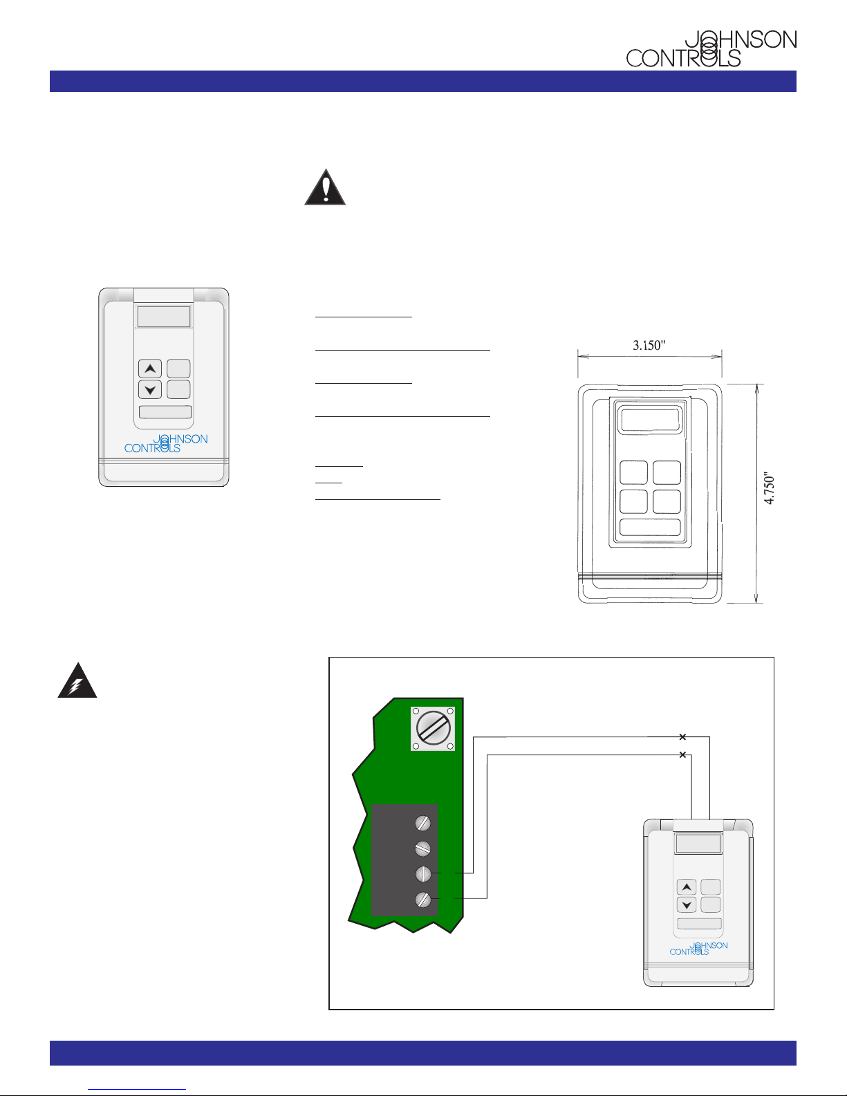
The Intelligent Thermostat has a space
temperature sensor, five user push buttons,
and a 2 line x 8 character dot matrix LCD
to show room temperature, time, outside air
temperature, setpoint, and other optional
parameters (depending upon the operation).
72 ° F
RoomTemp
ROOM/
OUTSIDE
*
OVERRIDE
Figure 1 - NXT-INT-01 Intelligent Thermostat
Installation
The thermostat connects to the controllers
via a 2-wire (#22 AWG, single twisted pair)
cable. The NexSys thermostat communications bus carries power and communications for the Intelligent thermostat.
Wiring
WARNING - TO PREVENT ELECTRI-
CAL SHOCK OR DAMAGE TO THE
EQUIPMENT, YOU MUST DISCON-
NECT THE POWER SUPPLY TO THE
ELECTRONIC CONTROLLER
BEFORE YOU MAKE THE WIRING
CONNECTIONS.
All wiring is low voltage and should be in
accordance with local regulations and the
National Electrical Code.
Use shielded cable only when it is required.
Most applications do not require shielding
and will benefit from unshielded cable.
When using the optional shielded cable,
ground only one end of the shield. Low
voltage control wiring should not be run in
the same conduit as line voltage wiring or
other conductors that supply highlyinductive loads (such as contactors, coils,
motors, generators, etc.).
CAUTION - MAKE ALL CONNEC-
TIONS AND CHECK ALL CONNEC-
TIONS BEFORE APPLYING
POWER. IMPROPER WIRING MAY
CAUSE PERMANENT DAMAGE TO
THIS EQUIPMENT.
Wiring Recommendations
Unshielded
Stranded, 22AWG: Belden #8442(2wire), Belden #8444(4-wire)
Plenum-rated, Stranded, 22AWG: Belden
#82442(2-wire), 82444(4-wire)
Stranded, 18AWG: Belden #8461(2wire), Belden #8489(4-wire)
Plenum-rated, Stranded, 18AWG: Belden
#87740(2-wire), 82489(4-wire)
Shielded
Stranded: Belden #8761
Solid: Belden #8450
Plenum-rated, Stranded: Belden
#88761other equipment.
To Wire the Intelligent Thermotat:
1. Connect the Red wire of the stat’s pigtail
to the STAT + terminal of the controller.
2. Connect the Black wire of the stat’s
pigtail to the controller’s STAT - terminal.
Refer to Figure 2 below.
ST- ST+ NET- NET+
Mounting
Mount the thermostat where it is exposed
to normal air circulation and where it senses
the average temperature of the space being
controlled (normally about 5 feet above the
floor). Do not mount it where it could be
affected by heat or cold from windows,
pipes, doors, lamps, sunlight, outside walls,
or other sources. See Figure 3 for dimensions.
Figure 3 - Intelligent Thermostat dimensions
BLACK
72 ° F
RoomTemp
OVERRIDE
ROOM/
OUTSIDE
*
RED
Electronic Systems USA, Inc.
Figure 2 - Wiring connection for the Intelligent Thermostat
Literature Part # 24-9869-5 Rev. A
www.johnsoncontrols.com
LIT-TD-2006 11/2002
Page 2
Room Sensor Installation - Page 2
Installation and Operation - Page
2
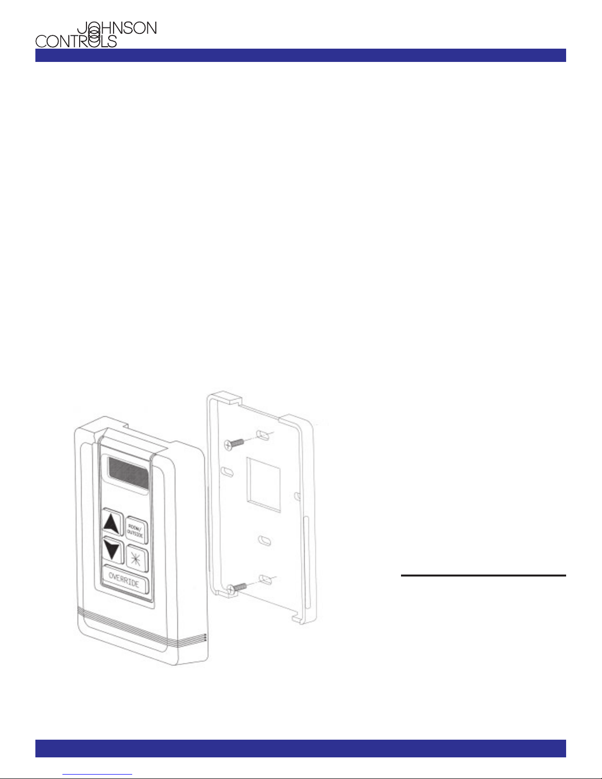
To mount the thermostat:
1. Install a 2” x 3” outlet box and the wiring
from the NexSys controller.
2. Pull the wiring from the outlet box and
insert it through the mounting bracket.
3. Assemble the mounting bracket to the
outlet box.
4. Connect the 2-wire pigtail from the
thermostat to the wires in the wall and
secure them with wire nuts. Obey wiring
polarity (see Figure 2).
5. Push excess wire into the outlet box.
6. Snap the cover onto the mounting
bracket.
Operation
Startup
Once activated, the Intelligent Thermostat
will display “ESUSA” then “Init. . .”
(initializing) on the LCD display window.
After five seconds, the thermostat will
send the current temperature and request
the Home Page parameter to update its
display.
If the thermostat detects a communications failure, “Com Fail” will display in the
display window for five seconds. “Retry”
will display when the thermostat attempts
to communicate again. Should the
thermostat detect a hardware or EEPROM
error, “Error” displays in the window.
Modes
The Intelligent Thermostat has three
operating modes: User, Configuration, and
Balance.
User Mode - In User Mode, the thermostat samples the space temperature and
allows the occupant to adjust the setpoint,
display parameters, and activate the
Override function.
Configuration Mode - A technician
accesses this mode by entering a password
value using the buttons on the thermostat.
In this mode, the thermostat becomes a
basic configuration tool that allows a
technician to view and/or edit the
controller’s configuration and all its
operating parameters.
Balance Mode - A technician accesses
this mode by entering a password value
using the buttons on the thermostat. This
mode allows a technician to adjust the
mechanical attributes of the entire VAV
system in order to bring the system into
proper operation.
This thermostat also provides an access
point to connect a PDA or laptop to the
thermostat communications bus. These
devices can then be used to command the
thermostat to Standby mode for one
minute periods.
Figure 4 - Mounting the Intelligent Thermostat
Repairs and Replacement
Do not make field repairs. Please
contact Johnson Controls at (800) 7657773 for replacement and other services.
Johnson Controls, Inc. reserves the
right to update specifications when
appropriate. Information contained in
this document is based on specifications believed to be correct at the
time of publication.
© 2000 Johnson Controls, Inc.
All rights Reserved.
LIT-TD-2006 11/2002
Literature Part # 24-9869-5 Rev. A
www.johnsoncontrols.com
 Loading...