

Page 1
Handheld VAV Balancing Tool
Installation Instructions
NS-ATV7003-0
Part No. 24-10211-2, Rev. C
Release 4.1
Issued October 6, 2008
Supersedes March 10, 2008
Applications
The Variable Air Volume (VAV) Balancing Tool allows
you to easily adjust and set the required parameters for
VAV applications that reside on the Metasys® system
VAV Modular Assembly (VMA) 1600 Series or Field
Equipment Controller (FEC) Series controllers.
The VAV balancing parameters display on the tool’s
Liquid Crystal Display (LCD). You use the dial and two
buttons on the tool to navigate through simple, intuitive
menus to balance the VAV box. The menus you see
are customized to the type of application residing in the
controller. The balancing operation also features an
adjustable time-out parameter that re tu rn s the to ol an d
controller to normal operation if you leave the controller
in balancing mode.
The handheld VAV Balancing Tool is lightweight and
portable. It can plug into any model of network sensor
to access the VAV controller.
The VAV Balancing Tool is compatible with the
following Metasys system BACnet® protocol devices:
• FEC loaded with a VAV application
• VMA1600 loaded with a VAV application
North American Emissions Compliance
United States
This equipment has been tested and found to comply
with the limits for a Class A digital device pursuant to
Part 15 of the FCC Rules. These limits are designed to
provide reasonable protection against harmful
interference when this equipment is operated in a
commercial environment. This equipment generates,
uses, and can radiate radio frequency energy, and if
not installed and used in accordance with the
instruction manual, may cause harmful interference to
radio communications. Operation of this equipment in a
residential area is likely to cause harmful interference,
in which case the user will be required to correct the
interference at his/her own expense.
Canada
This Class (A) digital apparatus meets all the
requirements of the Canadian Interference-Causing
Equipment Regulations.
Cet appareil numérique de la Classe (A) respecte
toutes les exigences du Règlement sur le matériel
brouilleur du Canada.
• Network Sensors connected to an FEC or
VMA1600 loaded with a VAV application
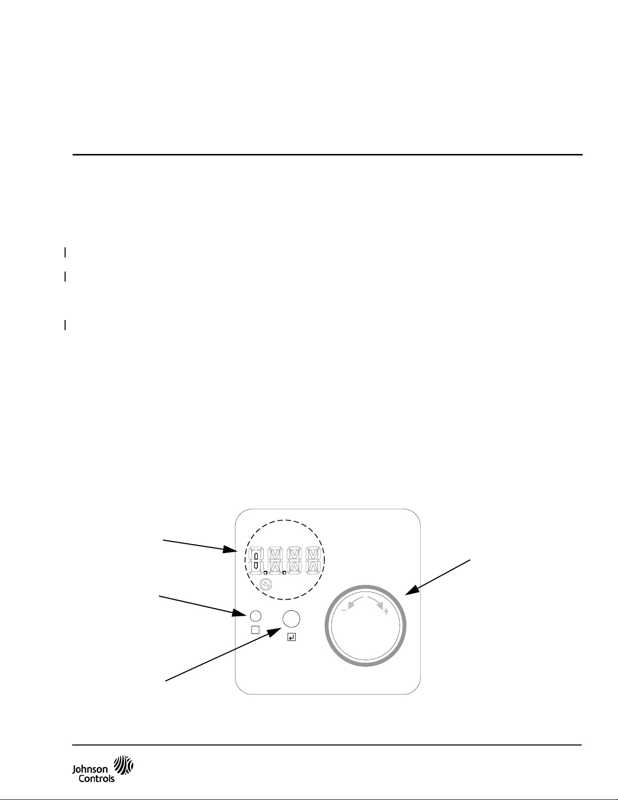
LCD with Backlight
Cancel Button
x
°F/°C
Enter Button
Figure 1: Front of the VAV Balancing Tool, 80 x 80 mm (3.2 x 3.2 in.)
Adjustment Dial
`
Handheld VAV Balancing Tool Installation Instructions 1
Page 2
Installation
Parts Included
• one handheld VAV Balancing Tool
• one 1.5 m (5 ft) retractable cable
• one laminated user guide (Metasys Balancing
Sensor User Guide [Part No. 24-10159-5])
• one padded carrying case
• one set of installation instructions
Special Tools Needed
The VAV Balancing Tool allows you to change the VAV
box parameters. To measure actual airflow and other
parameters, you need standard VAV measuring
equipment.
Do not plug the SA port cable into a standard phone
jack.
Note: Connect through the MS-ZFRCBL-0 when
connecting to a wireless-enabled VMA1600.
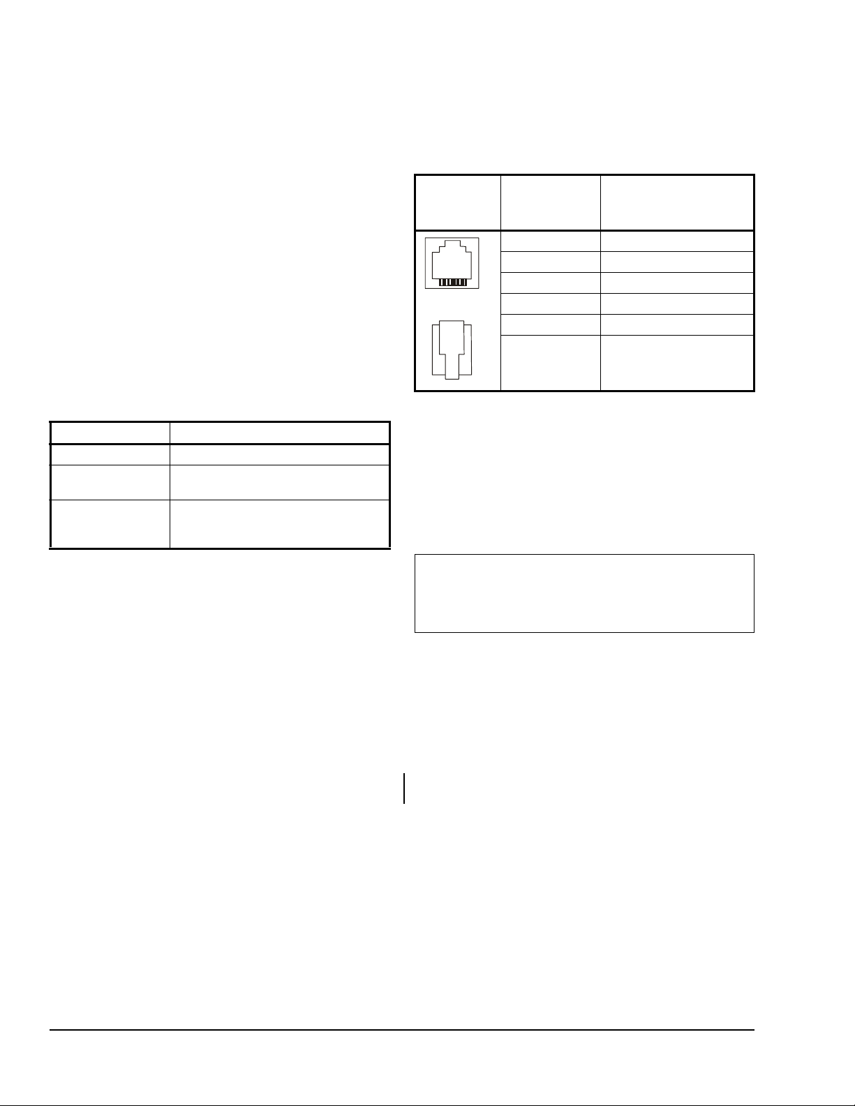
Table 2: SA Bus Port Pin Designations
Diagram Pin Number
Signal Name
(Both Ends
of Cable)
1 SA +
2 SA -
3 15 VDC Common
. . . .
6 16 1
4 +15 VDC
5 No Connection
6 No Connection
Accessories
Table 1: Products and Accessories (Order
Separately)
Code Number Description
NS-A TV7003-0 Handheld VAV Balancing Tool
MS-BTCVT-700 Cable replacement set; includes one
1.5 m (5 ft) retractable cable
MS-ZFRCBL-0 Wire harness with connectors for use
with some wireless enabled field
controllers.
Wiring
Wiring Consideration and Guidelines
Observe the following guidelines when wiring the
VAV Balancing Tool:
• Do not allow the VAV Balancing Tool to hang from
the cable connection.
• Provide some slack in the cable between the VAV
Balancing Tool and the controller or network
sensor.
Power Supply, Network, and Communication Connections
SA Bus Port
The Sensor-Actuator Bus (SA Bus) port on the
V AV Balancing Tool is a 6-pin, RS-485 port designed to
connect the VAV Balancing Tool to an accessible SA
Bus port on a Master-Slave/Token-Passing (MS/TP)
device. The MS/TP device is typically the network
sensor on the VAV controller SA Bus, using the cable
assembly provided. The SA Bus port is a straight
through, one-to-one connection (not a crossover). The
maximum allowable cable length is 100 ft.
6-pin
Connecting the VAV Balancing Tool
Observe the following guidelines and procedures when
connecting the VAV Balancing Tool to your system.
1. Connect one male end of the supplied cable to the
VAV Balancing Tool.
2. Connect the other end of the cable to the controller
or network sensor.
IMPORTANT: The VAV Balancing Tool has a
dedicated MS/TP bus address of 198. Only one VA V
Balancing Tool can be connected to the MS/TP bus
per physical trunk on the system.
Setup and Adjustments
The VAV Balancing Tool device itself requires no
commissioning.
Operation
Using the VAV Balancing Tool
Once the VAV Balancing Tool is physically connected
to the SA bus of the VMA or FEC controller, you can
use the tool to balance the VAV box. Refer to the VAV
Balancing Tool Technical Bulletin (LIT-12011087).
Repair Information
Do not open the VAV Balancing Tool housing. The VAV
Balancing Tool has no user-serviceable parts inside.
The VAV Balancing Tool requires no periodic field
maintenance.
Handheld VAV Balancing Tool Installation Instructions2
Page 3

Technical Specifications
Handheld VAV Balancing Tool
Product Code NS-ATV7003-0
Power Requirements 15 VDC Nominal, provided through the SA Bus Port; Consumption is 1.35 watts maximum
Terminations 6-Position Modular Jack
Transmission Speed Serial Communication (SA Bus)
9600, 19.2k, 38.4k, or 76.8k bps
Sensor Addressing Fixed Address of 198
Cable 1.5 m (5 ft) retractable cable
Ambient
Conditions
Compliance United States UL Listed, File E107241, CCN PAZX7, Under UL 916, Energy Management
Dimensions 80 x 80 x 250 mm (3.2 x 3.2 x1.0 in.)
Shipping Weight 0.165 kg (0.365 lb)
Operating 0 to 50°C (32 to 122°F); 5 to 95% RH, Noncondensing; 30°C (86°F) Maximum Dew Point
Storage -40 to 85°C (-40 to 185°F); 5 to 95% RH, Noncondensing
FCC Compliant to CFR 47, Part 15, Subpart B, Class A
Canada UL Listed, File E107241, CCN PAZX7, Under CSA C22.2 No. 205, Signal Equipment
Industry Canada, ICES-003
Europe CE Mark, EMC Directive 89/336/EEC;
EN61000-6-3 (2001) Generic Emission Standard for Residential and Light Industry;
EN61000-6-2 (2001) Generic Immunity Standard for Heavy Industrial Environment
Australia and
New Zealand
C-Tick Mark, Australia/NZ Emissions Compliant
The performance specifications are nominal and conform to acceptable industry standard. For application at conditions beyond these
specifications, consult the local Johnson Controls® office. Johnson Controls, Inc. shall not be liable for damages resulting from
misapplication or misuse of its products.
Building Efficiency
507 E. Michigan Street, Milwaukee, WI 53202
Metasys® and Johnson Controls® are registered trademarks of Johnson Controls, Inc.
All other marks herein are the marks of their respective owners. © 2008 Johnson Controls, Inc.
Handheld VAV Balancing Tool Installation Instructions 3
Published in U.S.A. www.johnsoncontrols.com
 Loading...