

Page 1

NAE55/NIE55 Installation Guide
Application
The Network Automation Engine (NAE) and Network Integration Engine (NIE) are web-enabled,
Ethernet-based, supervisory devices. NAEs and NIEs monitor and control networks of fieldlevel building automation devices, including HVAC equipment, lighting, security, and fire safety
equipment. Figure 1 shows a typical network engine.
In this installation guide, the term network engine applies to any NAE55 or NIE55 model, unless
otherwise stated. For installation instructions on the secure NAE55, refer to the NAE-S Installation
Instructions (Part No. 24-10051-108). For installation instructions on the NAE55s that are approved
for Metasys® system smoke control applications, refer to the NAE55 Installation Instructions (Part No.
24-10051-00132).
The NAE55 models provide integration to the following network protocols: BACnet/IP, BACnet MS/
TP, and N2 Bus, and integrations to other building management communication technologies,
including Modbus®, M-Bus, and KNX. At Release 9.0, the Modbus, M-Bus, and KNX integrations are
added and licensed during network engine commissioning. At Release 10.0, the Modbus, M-Bus,
and KNX integrations are included with the image of the network engine, already pre-licensed and
ready for selection during commissioning. .
Important: For any other custom integrations, contact your local Systems Integration Services
(SIS) team before an upgrade. Updated drivers are available on request.
Note: The NIE55 is available at Release 9.0, but beginning at Release 10.0, the NIE55 is no
longer offered. Also, for installation instructions on the secure NAE55, refer to the NAE-S
Installation Instructions (Part No. 24-10051-108).
Note: Beginning with Metasys Release 10.0, modems (internal and external) and pagers are
no longer supported on NAE55 engines that run the Linux operating system, but are still
supported on prior releases for engines that use a Windows Embedded operating system. If
you receive from the factory a network engine with Release 9.0 that has an internal modem,
you can field-upgrade the engine to Release 10.0 to acquire new release enhancements, but
its modem and pager functionality is lost. If you need modem and pager functionality, do not
upgrade the NAE55 engine to Release 10.0.
Note: If you receive an NAE55 engine from the factory that is imaged with Release 9.0, you
can field-upgrade the engine to Release 10.0 if the upgrade is supported.
Installation
Follow these guidelines when installing the network engine:
• Transport the network engine in the original container to minimize vibration and shock damage
to the network engine.
• Verify that all the parts shipped with the network engine. The data protection battery and
network engine ship together but are packaged separately.
• Do not drop the network engine or subject it to physical shock.
• Do not open the network engine housing (except the data protection battery compartment). The
network engine has no user-serviceable parts inside.
Part No. 24-10051-43 Rev. T
2019-05-08
Release 9.0, 10.0
*241005143T*
(barcode for factory use only)
MS-NAE55xx-3, MS-NIE55xx-3
Page 2
Parts included
• one MS-NAE55xx-x or MS-NIE55xx-x model
• one data protection battery
• one installation instructions sheet
Materials and special tools needed
• four fasteners appropriate for the mounting surface (M4 screws - Europe, #8 screws - North
America)
• two 36 cm (14 in.) or longer pieces of 35 mm DIN rail (for DIN rail mount applications only)
Physical Features
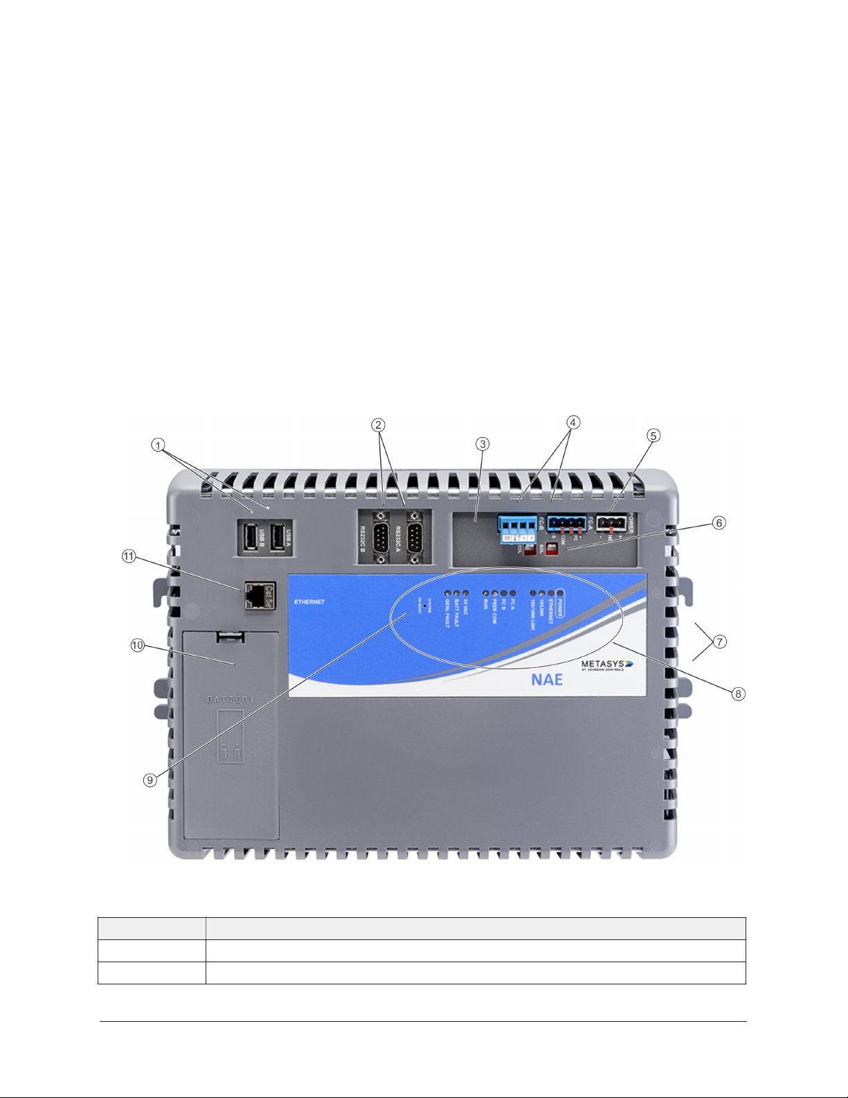
The following figure displays the physical features of the network engine. The accompanying table
provides a description of the physical features. A modem jack appears on NAE55 models with an
internal modem (not shown).
Figure 1: Physical features of Network Engine (MS-NAE5510-3 shown)
Table 1: Network Engine physical features
Callout Description
1 USB ports
2 RS-232 serial ports
NAE55/NIE55 Installation Guide2
Page 3
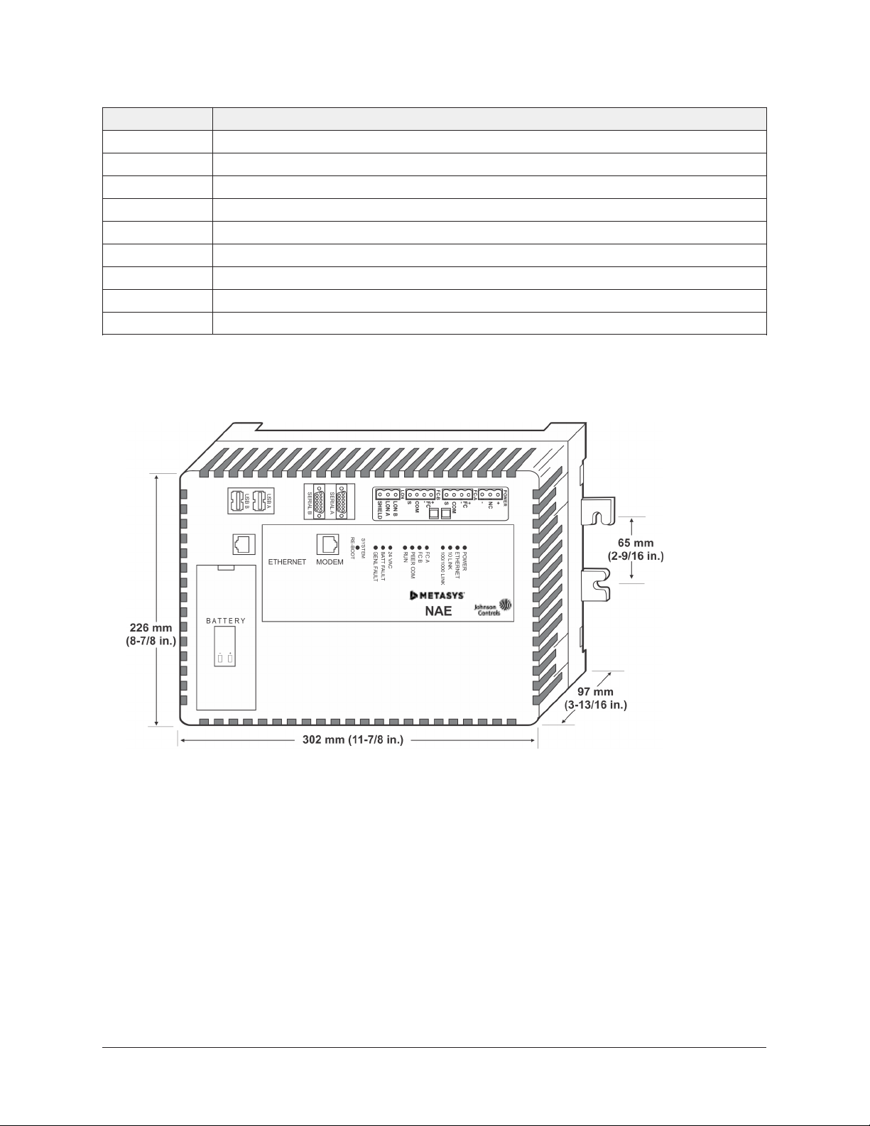
Table 1: Network Engine physical features
Callout Description
3 LonWorks terminal (LonWorks models only)
4 Field controller buses (FC Bus or N2 Bus terminal)
5 24 VAC power terminal
6 End-of-line switches
7 Wall mount feet
8 System status LEDs
9 System reboot switch
10 Data protection battery compartment
11 RJ-45 8-pin Ethernet port
Dimensions
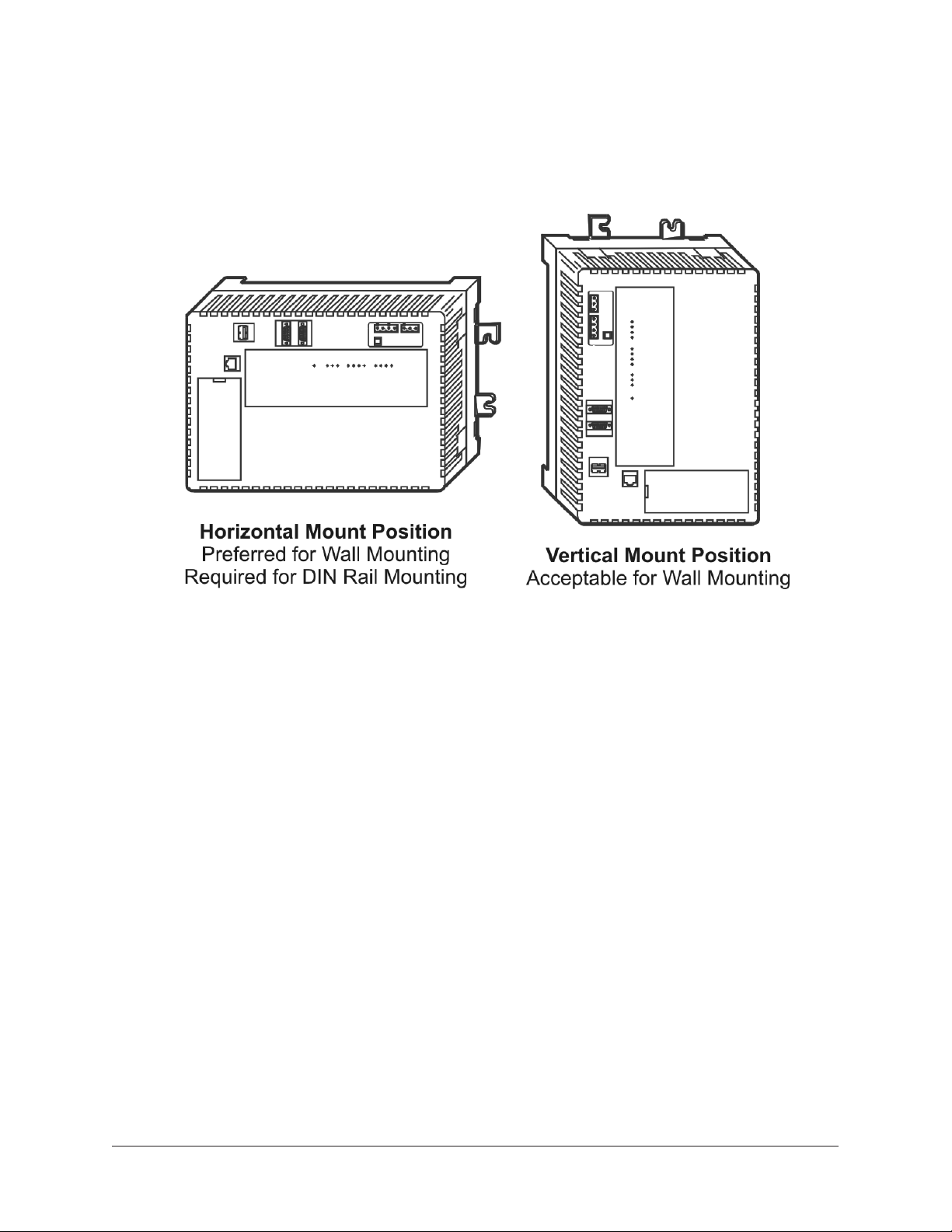
Figure 2: NAE55 showing dimensions and mounting orientation
Mounting
Location considerations
Follow these guidelines when mounting the network engine:
• Ensure that the mounting surface can support the network engine and any user-supplied
enclosure.
• Mount the network engine in the proper orientation (Figure 5).
• Mount the network engine on an even surface in wall mount applications whenever possible.
If you must mount the network engine on an uneven surface, be careful not to crack the wall
mount feet or housing when tightening the screws. Use shims or washers to mount the unit
securely on the mounting surface.
3NAE55/NIE55 Installation Guide
Page 4
• Mount the network engine in areas free of corrosive vapors and observe the environmental
limitations listed in the Technical specifications section.
• Do not mount the network engine on surfaces that are prone to vibration or in areas where
electromagnetic emissions from other devices or wiring can interfere with network engine
communication.
• Allow sufficient space for running cable and wire, making terminal connections, and accessing
battery compartment (Figure 3).
• Mount the power supply above the network engine to ensure adequate heat dissipation and to
position close to the power wiring conduit.
On panel or enclosure mount applications, observe these additional guidelines:
• Do not install the network engine in an airtight enclosure.
• Mount the network engine so that the enclosure wall or the transformer does not obstruct
ventilation of the network engine housing.
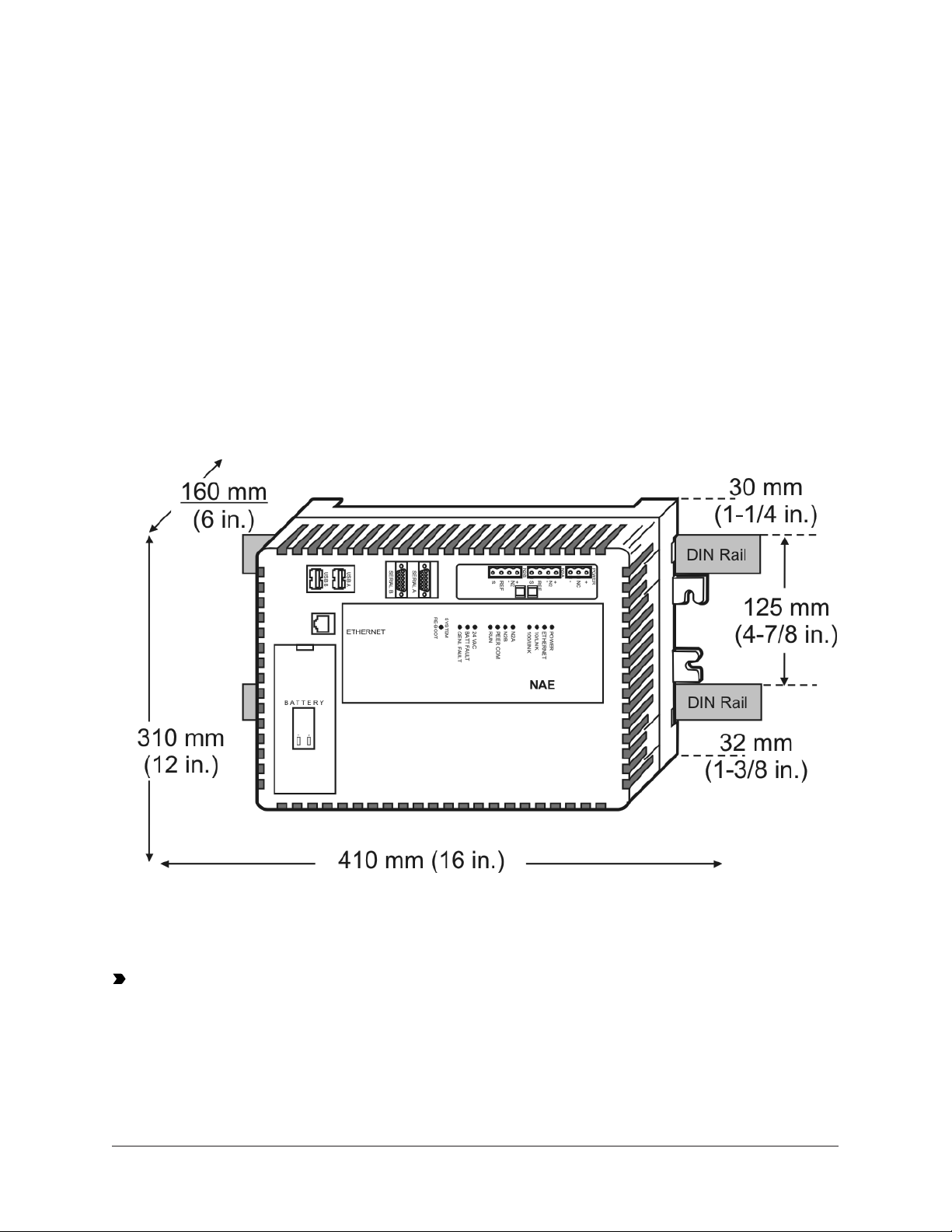
Figure 3: Network Engine DIN rail mount dimensions
and mounting space requirements, mm (in.)
Each network engine application is different, and no general guidelines can be given about the
heat dissipating devices that may be mounted in an enclosure with the network engine. Monitor
the network engine processor temperature for each application to determine the acceptable
combinations of devices and proper mounting location for your specific application.
Important: Do not add any devices to an enclosure with a network engine that could cause
the temperature of the network engine processor to exceed 70˚C (158˚F). View the network
engine's CPU Temperature value on the network engine's Diagnostic tab on the Metasys Site
Management Portal. See Technical specifications for ambient condition requirements, and
refer to the Troubleshooting section of the NAE Commissioning Guide (LIT-1201519) for additional
information.
NAE55/NIE55 Installation Guide4
Page 5
Wall mount applications
To mount the network engine on a vertical surface:
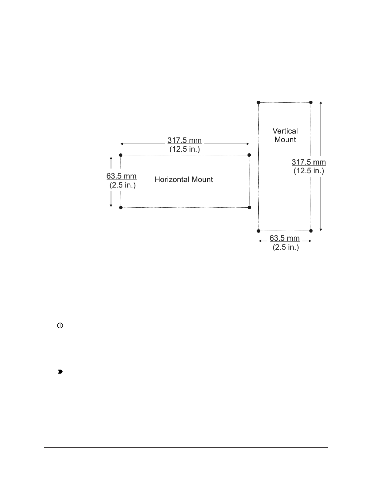
1. Mark the location of the four wall mount feet on the wall using the dimensions in Figure 4 and
an orientation shown in Figure 5, or hold the network engine up to the wall and mark the hole
locations.
Figure 4: Mounting screw hole dimensions, mm (in.)
2. Drill holes in the wall at the marked locations.
3. Insert appropriate wall anchors in all four holes (if necessary) and insert the screws into the
top two holes. Leave enough space between the wall surface and the screw head for the wall
mount feet.
4. Hang the network engine on the screws with the top wall mount feet for horizontal wall mount
applications. Hold the network engine in place for vertical application.
Note: The wall mount feet are designed to make mounting easier. When the network
engine is wall mounted in the horizontal orientation, you can hang the network engine on
the screws with the upper two mount feet (Figure 5).
5. Insert the screws into the lower two wall mount feet and holes and carefully tighten all of the
screws.
Important: Do not overtighten the mounting screws. Overtightening the screws can crack
the network engine wall mount feet or housing.
DIN rail mount applications
To mount the network engine on DIN rails:
1. Mount two DIN rails horizontally, so they are 125 mm (4.9 in.) apart on centers (Figure 3).
2. Snap the DIN clips on the bottom of the network engine to the outward position.
5NAE55/NIE55 Installation Guide
Page 6
3. Hang the network engine on the DIN rail hooks on the back of the network engine.
Press the DIN clips back into position to secure the unit on the DIN rails.
Figure 5: Required orientations for Network Engine wall mount applications
To remove the network engine from the DIN rails:
1. Snap the DIN clips on the bottom of the network engine to the outward position.
2. Lift the network engine off the DIN rails.
Enclosure mount
To mount the network engine in an enclosure:
1. Mount the enclosure in accordance with the manufacturer’s instructions.
2. Mount the network engine in the enclosure following the guidelines in the Location
considerations and Mounting sections of this document.
NAE55/NIE55 Installation Guide6
Page 7

Wiring Overview
Power supply, network, and communication connections
See Figure 1 for the location of the power supply terminal, network communication terminals,
Ethernet jack, and modem jack.
Depending on the model, the network engine can connect to an MS/TP field bus trunk, an N2 Bus
trunk, or a LonWorks network trunk. Also, all network engines support two vendor integrations,
such as two Modbus, two M-Bus, or one of each. Or, if a KNX integration is required, three KNX IP
Gateways are supported for one network engine. See Table 13 for a list of all supported dual trunk
applications. The rules, guidelines, and wiring considerations for each type of network or field bus
application are provided in tables of this document.
Power supply
Important: Install the data protection battery before applying 24 VAC power to the network
engine. See the Installing the data protection battery section.
In North America, use a Class 2, 24 VAC power supply with a 50 VA minimum output. Outside North
America, use a 24 VAC SELV transformer at the appropriate rating. The minimum input voltage for
the network engine to operate properly is 20 VAC. See the Technical specifications section.
Use a dedicated power supply to the network engine only. Do not connect any other loads to the
power supply. Additional loads may cause noise interference.
Ethernet port
The Ethernet port, labeled ETHERNET, is an 8-pin RJ-45 network port for connecting the network
engine to Ethernet IP networks. Network engine can connect to Ethernet networks at 10 Mbps, 100
Mbps, or 1 Gbps. This Ethernet port provides IP communications over the building network and to
any third-party integration that uses Ethernet communication, including Modbus TCP, M-Bus TCP,
or KNX.
FC Bus terminal block
The two Field Controller (FC) Bus connections on a network engine are 4-pin removable, keyed
terminal blocks labeled FC-A and FC-B.
The FC bus connections are optically isolated RS-485 ports with keyed 4-position terminal blocks
that communicate at 9.6k, 19.2k, 38.4k, or 76.8k baud. Use an FC Bus port to integrate an N2
network, BACnet MS/TP FC Bus trunk, or third-party network into the Metasys system.
Note: N2, BACnet MS/TP, Modbus RTU, and M-Bus have different protocols and network
requirements. Do not intermix N2, MS/TP, Modbus, or M-Bus devices on the same FC Bus port.
The SHD connections on the FC terminal blocks are not connected to any earth ground connection.
The FC A and FC B terminal blocks are not interchangeable.
LonWorks network terminal block
The LonWorks TP/FT-10 network connection, available only on the network engine LonWorks
model, is a 3-wire removable, keyed terminal block. The Shield connection on the LonWorks
network terminal block is an isolated terminal and is not connected in the network engine. Use the
LonWorks terminal block to connect LonWorks networks to the network engine.
Computer serial ports
The network engine has two RS-232-C serial ports labeled RS232C A and RS232C B (Figure 1). These
serial ports are for direct connection using a standard 9-pin female data terminal equipment (DTE)
to 9-pin female DTE null modem cable. The NAE55 serial ports do not support external modems.
7NAE55/NIE55 Installation Guide
Page 8
For an NAE55 at Release 9.0, you can use the RS232C A port to connect directly to a computer
serial port to browse to the NAE55. Use this port only for establishing a Point-to-Point Protocol
(PPP) network connection. Refer to the Metasys System Extended Architecture Direct Connection and
Dial-Up Connection Application Note (LIT-1201639). Use the RS232C B port to connect with a VT100
terminal or computer using a VT100 terminal emulator because the RS232C B port outputs the
device IP address. Use this port only to obtain the NAE55 IP address at startup. Refer to the NAE
Commissioning Guide (LIT-1201519).
For an NAE55 at Release 10.0 or later, the RS232C A port is inactive. However, you can use the
RS232C B port to connect a Modbus RTU third-party integration. For more information on how to
use the serial port for third-party vendor integration, refer to the application note for the particular
vendor integration you are installing.
Universal Serial Bus (USB) ports
The two USB ports labeled USB A and USB B are both configured as masters and are independent
of each other. At Release 9.0, you can use USB A port to connect an optional external modem. Refer
to the NAE Commissioning Guide (LIT-1201519) for more information on external modems. At Release
10.0 or later, the use of a USB port to connect an optional external modem is no longer supported.
However, you can use either the USB A or USB B port for debugging purposes when integrating to
a third-party protocol (for example, Modbus, M-Bus, or KNX).
Optional Internal Modem
MS-NAE55x1-x and MS-NIE55x1-x models with Release 9.0 have an internal modem and a 6-pin
RJ-12 modular jack labeled MODEM. Connect a standard phone line plug and cable to the to use the
internal modem.
For information on commissioning an internal modem, refer to the NAE Commissioning Guide
(LIT-1201519).
Wiring the Network Engine
Mount the network engine securely before wiring it. For details, see Mounting.
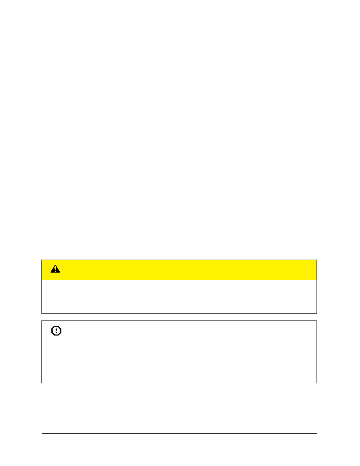
CAUTION
Risk of Property Damage.
Do not apply power to the system before checking all wiring connections. Short circuited or improperly
connected wires may result in permanent damage to the equipment.
Attention
Risque de dégâts matériels.
Ne pas mettre le système sous tension avant d'avoir vérifié tous les raccords de câblage. Des fils
formant un court-circuit ou connectés de façon incorrecte risquent d'endommager irrémédiablement
l'équipement.
NAE55/NIE55 Installation Guide8
Page 9
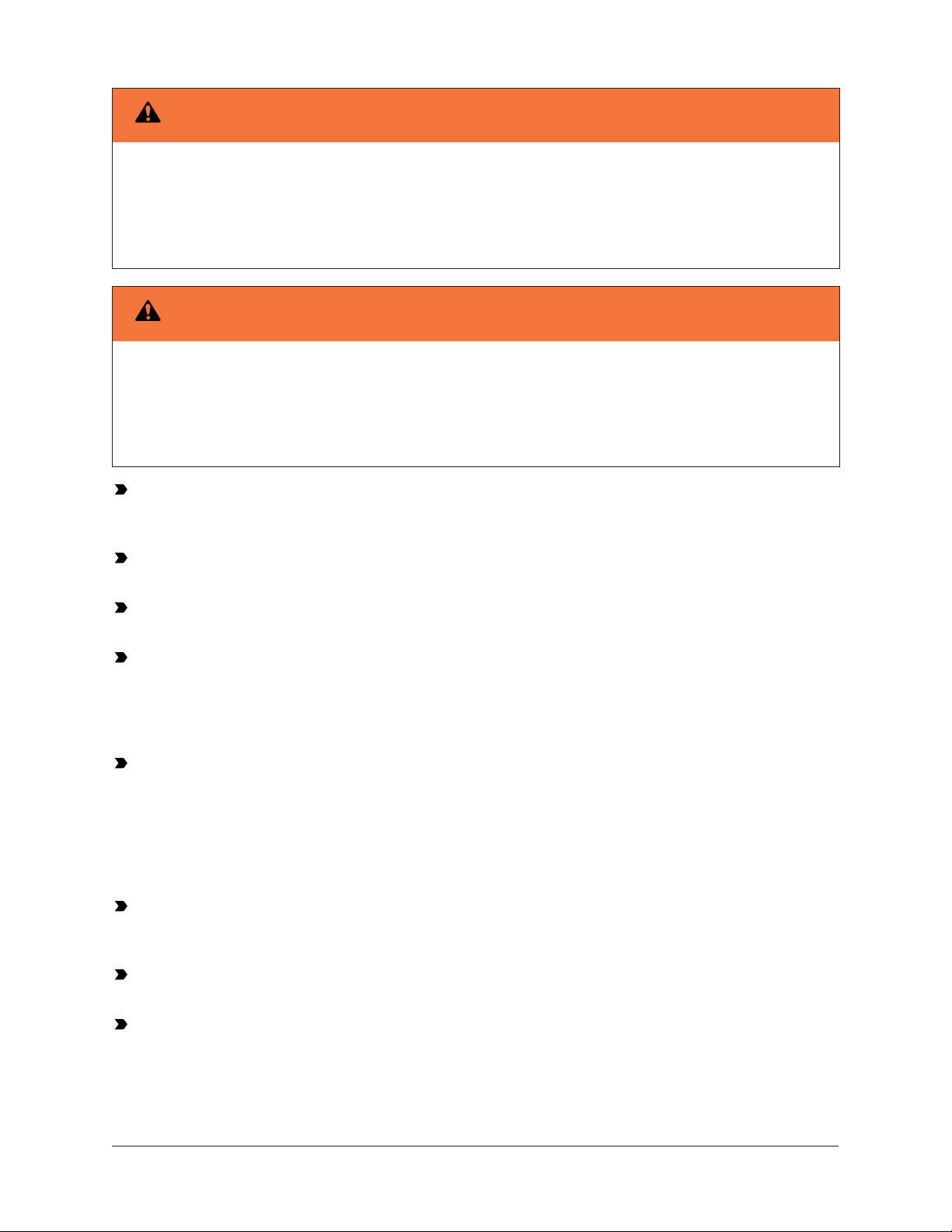
Warning
Risk of Electric Shock.
Disconnect or isolate all power supplies before making electrical connections. More than one
disconnection or isolation may be required to completely de-energize equipment. Contact with
components carrying hazardous voltage can cause electric shock and may result in severe personal
injury or death.
Warning
Risque de décharge électrique.
Débrancher ou isoler toute alimentation avant de réaliser un branchement électrique. Plusieurs
isolations et débranchements sont peut-être nécessaires pour -couper entièrement l'alimentation
de l'équipement. Tout contact avec des composants conducteurs de tensions dangereuses risque
d'entraîner une décharge électrique et de provoquer des blessures graves, voire mortelles.
Important: Do not apply 24 VAC power to the network engine before completing and checking
connections. Short circuits or improperly connected wires may result in permanent damage to
the equipment.
Important: Do not apply 24 VAC power to the network engine before installing the data
protection battery. See the Installing the data protection battery section in this document.
Important: Use copper conductors only. Make all wiring in accordance with local, national,
and regional regulations.
Important: Use this MS-NxE55xx-x only as an operating control. Where failure or malfunction
of the NxE55 could lead to personal injury or property damage to the controlled equipment or
other property, additional precautions must be designed into the control system. Incorporate
and maintain other devices, such as supervisory or alarm systems or safety or limit controls,
intended to warn of or protect against failure or malfunction of the NxE55.
Important: Utiliser ce MS-NxE55xx-x uniquement en tant que dispositif de contrôle de
fonctionnement. Lorsqu'une défaillance ou un dysfonctionnement du NxE55 risque de
provoquer des blessures ou d'endommager l'équipement contrôlé ou un autre équipement, la
conception du système de contrôle doit intégrer des dispositifs de protection supplémentaires.
Veiller dans ce cas à intégrer de façon permanente d'autres dispositifs, tels que des systèmes
de supervision ou d'alarme, ou des dispositifs de sécurité ou de limitation, ayant une fonction
d'avertissement ou de protection en cas de défaillance ou de dysfonctionnement du NxE55.
Important: The network engine is a low-voltage (<30 VAC) device. Do not exceed the network
engine electrical ratings. Applying high voltage to the network engine may result in permanent
damage to the network engine and void any warranties.
Important: Do not remove the terminal block keys. The terminal block plugs and the terminal
sockets are keyed to fit together in the correct configuration only.
Important: Prevent any static electric discharge to the network engine. Static electric
discharge can damage the network engine and void any warranties.
Be sure to follow these wiring guidelines:
9NAE55/NIE55 Installation Guide
Page 10
• Route the supply power wires and communication cables at least 50 mm (2 in.) away from the
vent slots in the sides of the network engine housing.
• Provide slack in the wires and cables. Keep cables routed neatly around the network engine to
promote good ventilation, LED visibility, and ease of service.
• Ensure that the building automation network wiring meets the specifications, rules, and
guidelines as outlined in the Wiring considerations and guidelines for network integrations
section. The network engine does not require an earth ground connection.
• Follow the transformer manufacturer’s instructions and the project installation drawings. Power
supply wire colors may be different on transformers not manufactured by Johnson Controls.
• While connecting network devices to 24 VAC power, make sure that transformer phasing is
uniform across all devices. Powering network devices with uniform 24 VAC supply power phasing
reduces noise, interference, and ground loop problems.
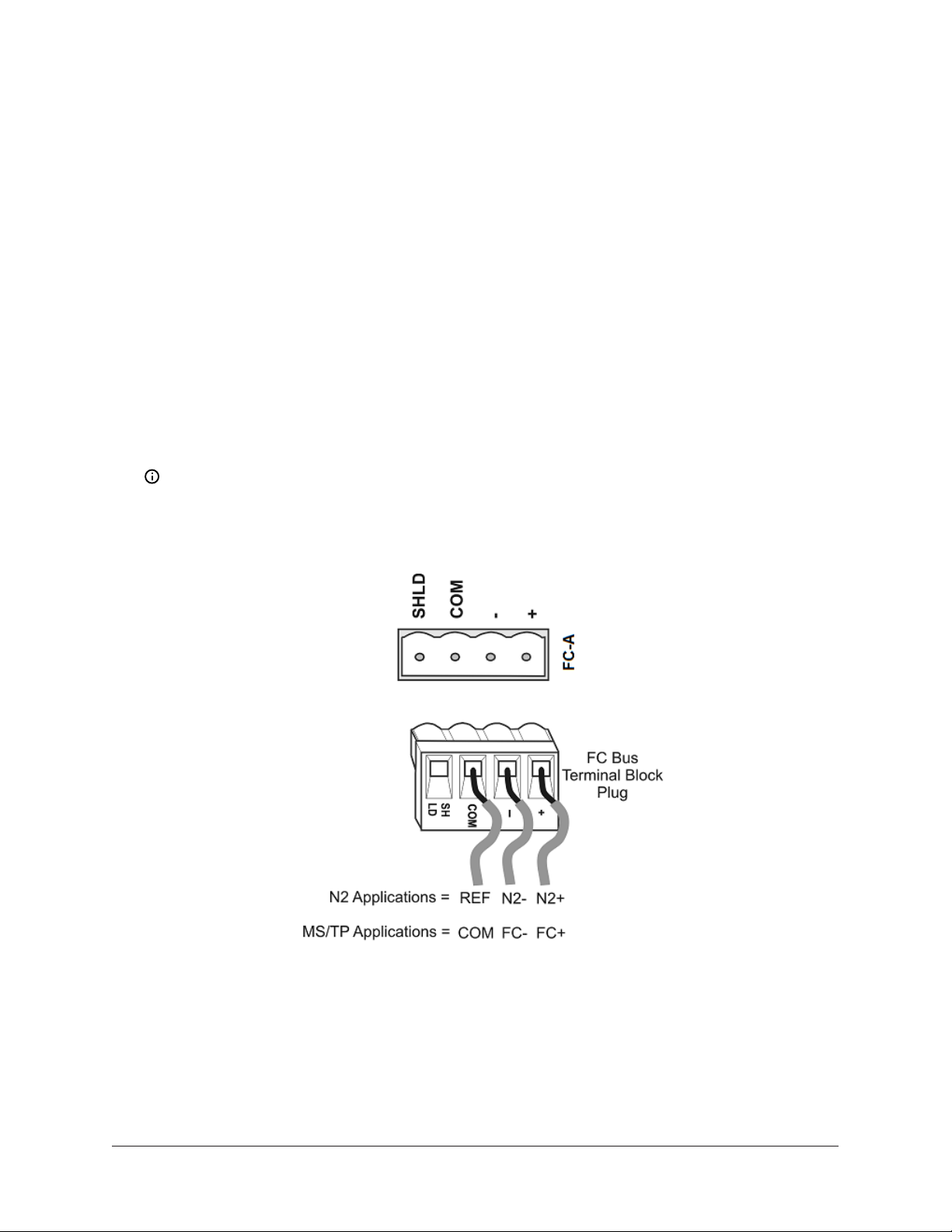
Connecting the FC Bus
To connect devices to the MS/TP Field Controller (FC) Bus, complete the following steps:
1. Connect the 3-wire bus cable to the removable blue 4-pin terminal block labeled FC-A as shown
in Figure 6.
Note: The FC-A and FC-B terminals can accept either the MS/TP FC Bus or the N2 Bus, but
not a mixture of both on the same trunk. If you want to integrate both the MS/TP Bus and
the N2 Bus, select one FC terminal for MS/TP FC Bus use and the other for N2 Bus use.
Figure 6: FC Bus terminal block and wiring connections
2. To add additional field devices, wire from one device to the next as shown in Figure 7. Do not
connect more than two wires to each terminal to ensure that a daisy chain configuration is
used.
NAE55/NIE55 Installation Guide10
Page 11
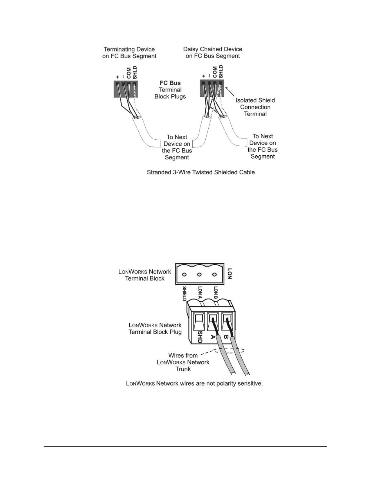
Figure 7: Daisy chained devices
3. Set each FC EOL switch to their proper positions. See the note in Setting the end-of-line
switches.
Connecting the LonWorks Network
1. Connect the 2-wire cable from the LonWorks network trunk to the removable 3-terminal blue
plug labeled LON (Figure 1). The LonWorks network trunk is available on the MS-NAE5520-3
model only.
Figure 8: LonWorks network terminal block and wiring connections
2. To add additional vendor devices, wire from one device to the next in a daisy-chained fashion.
Do not connect more than two wires to each terminal.
11NAE55/NIE55 Installation Guide
Page 12

Connecting Modbus RTU devices
To connect a Modbus RTU device to the network engine, complete the following steps:
1. For a Modbus RTU device that requires an RS-485 connection, terminate the 3-wire bus cable
from the Modbus device to one of the removable 4-terminal blue plugs on the network engine,
labeled FC-A and FC-B (Figure 9).
Figure 9: FC Bus terminal block and wiring connections
2. For a Modbus RTU device that requires an RS232C serial connection, use a cable to connect
the converter to the RS232C B serial port on the network engine. The maximum cable length
between devices connected though an RS-232 line depends on the baud rate used. In general,
the cable should not exceed 15 meters for 9600 baud.
3. Wire from the RS-485 terminal on the converter to the RS-485 port on the vendor device (Figure
10). The RS-485 bus is a two-wire network.
a. Connect the converter's + A terminal to the device's + (or A) terminal.
b. Connect the converter's - B terminal to the device's - (or B) terminal.
c. If the device has a Signal Ground or Reference terminal, connect this to the converter's
CG2 terminal.
Figure 10: Connection between converter and device
NAE55/NIE55 Installation Guide12
Page 13

4. To add additional vendor devices, wire from one device to the next in a daisy chain
configuration. The completed wiring should look similar to Figure 11.
Figure 11: Modbus RTU wiring detail overview
Connecting M-Bus devices
To connect a M-Bus device to the network engine, complete the following steps:
1. Connect from the RS232C B serial port on the network engine to the RS-232 connector of the
level converter. Wire to terminals GND, RxD, and TxD as shown in Figure 12.
2. Wire from the M- and M+ terminals on the level converter (Figure 12) to the meters using a
free (star, tree, or line) topology. Specific cabling can vary depending on the topology and site.
See Wiring considerations and guidelines for network integrations.
Note: If the number of M-Bus unit loads or distances exceeds the specifications of a level
converter, an M-Bus repeater can be wired to the converter to increase the number of unit
loads and distances. The converter shown in Figure 12 is capable of handling up to 6 units
loads, while other models can handle up to 100. See Ordering information for a list of MBus devices.
3. Connect the 24 VAC supply power wires from the transformer to the -/~ and +/~ terminals as
shown in Figure 12.
13NAE55/NIE55 Installation Guide
Page 14

Connecting KNX devices
Figure 12: M-Bus Level Converter
1. Connect an Ethernet cable from the building's network jack to the port on the front of the KNX
gateway (Figure 13).
Note: Depending on the size of your network, you can use either a KNX Interface or
Router as a gateway. The Interface connects the network engine to a single KNX line,
while the Router acts as both an Interface and a Line Coupler over Ethernet to connect the
network engine to the network, not to a single device.
2. Connect an Ethernet cable from the building's network jack to the RJ-45, 8-pin Ethernet port on
the network engine.
NAE55/NIE55 Installation Guide14
Page 15

Figure 13: KNX/IP interface router
3. For a single KNX line, wire from the red and black terminals on the gateway to the devices. For
multiple KNX lines, wire from the red and black terminals on each gateway to the devices on
the same KNX line.
Note: Specific cabling can vary depending on the topology and site. See Wiring
considerations and guidelines for network integrations.
4. Wire each KNX gateway to its own dedicated power supply on the KNX line.
Connecting other third-party devices
The network engine supports several other third-party devices. Refer to the following documents
for information about how to connect the network engine to these devices:
• C•CURE-victor: NAE Commissioning for C•CURE-victor Integration Application Note (LIT-12013151)
• Simplex FACU: NAE Commissioning for Simplex Fire System Integration (LIT-12013060)
• Cree SmartCast Lighting Control: Metasys System Commissioning for CREE Digital Lighting Systems
Integration (LIT-12013152)
• Molex Lighting Control: Metasys System Commissioning for Molex Digital Lighting Systems
Integration (LIT-12013153)
Connecting the power source
Connect the 24 VAC supply power wires from the transformer to the removable power terminal
connector on the network engine (Figure 14). The connections are HOT and COM (common).
15NAE55/NIE55 Installation Guide
Page 16

Do not apply power yet.
Figure 14: Supply power wiring (24 VAC transformer)
Note: Power supply wire colors may be different on transformers not manufactured by
Johnson Controls. Follow the transformer manufacturer’s instructions and the project
installation drawings.
NAE55/NIE55 Installation Guide16
Page 17

Setup and adjustments
Installing the data protection battery
Important: Do not apply 24 VAC power to the network engine before installing the data
protection battery.
To install the data protection battery:
1. Remove the battery from its packaging. Remove the battery cover on the network engine to
expose the battery compartment (Figure 1).
2. Carefully plug the network engine battery connector from the battery compartment into the
connector on the battery cable (Figure 15).
3. Place the battery into the compartment (Figure 15).
4. Slide one end of the battery strap into the hole on the opposite side of the strap (Figure 15),
and loop the strap tightly around the battery to minimize battery movement.
5. Replace the cover of the battery compartment.
Important: The data protection battery must maintain a small residual charge. The battery
ships from the factory with a small residual charge. You should connect 24 VAC power to the
network engine immediately after connecting the battery to ensure that the battery does not
completely loose its charge, which may damage the battery.
Note: The 24 VAC power to the network engine charges the data protection battery. At initial
startup, the battery requires a charging period of at least two hours before it supports data
protection if power fails. Maximum protection (up to three consecutive power failures without
recharging time) requires a 24-hour charging period.
Figure 15: Network Engine data protection battery
17NAE55/NIE55 Installation Guide
Page 18

Setting the end-of-line switches
The network devices at each end of an FC Bus segment must be set as network terminated devices.
The network engine has two EOL switches (one for each FC Bus) that enable you to set the network
engine as a network terminated device on the bus.
To set a network engine as an FC Bus terminated device, position the switch on the EOL switch
block to the ON position (Figure 16).
Figure 16: FC Bus EOL switch in the factory default ON (up) position
Note: The EOL switches on the network engine are factory set to ON (Figure 16). If the network
engine is not a terminated device on the FC Bus, reposition the switch on the EOL switch block
to the Off (down) position.
Set the EOL switches appropriately for the FC A and FC B buses. The network engine follows the
same rules as other switch-terminating devices listed in the Setting Terminations sections of the
N2 Communications Bus Technical Bulletin (LIT-636018) and the MS/TP Communications Bus Technical
Bulletin (LIT-12011034).
Powering on the Network Engine
Apply power to the network engine by plugging in the gray 2-pin terminal connector to the power
terminal port on the network engine (Figure 1). The network engine requires approximately 3
minutes to start up and become operational. See the LED test sequence at startup section.
Startup is complete and the network engine is operational when the (green) RUN LED is On steady
and the (red) GEN FAULT LED is Off. See Figure 17 for LED locations.
Disconnecting power from the Network Engine
Important: The data protection battery must be installed and charged before disconnecting
the 24 VAC supply power.
Disconnect power from the network engine by removing the gray 2-pin terminal block from the
power terminal port on the network engine (Figure 1).
When you remove 24 VAC power from the network engine, or supply power is lost, the network
engine is nonoperational. The POWER LED (Figure 17) remains On, and the data protection battery
continues to power the network engine for approximately 1 to 3 minutes so that volatile data can
be backed up in nonvolatile memory. The POWER LED goes Off when the data backup is completed.
NAE55/NIE55 Installation Guide18
Page 19

Troubleshooting
LED status indicators
The LEDs on the front cover of the network engine indicate power and communication status. See
Figure 17 and Table 2.
LED test sequence at startup
During startup, the network engine automatically initiates an LED test to verify the operational
status of the LEDs. Immediately after connecting supply power, the following LED lighting sequence
occurs:
1. The network engine emits one short beep, indicating that the BIOS startup was successful.
2. The PEER COM, RUN, and GENL FAULT LEDs turn on, indicating that the OS is booting up. For
network engine models, the FC A and FC B LEDs also turn on.
3. The PEER COM, RUN, GENL FAULT LEDs, and the FC A and FC B LEDs shut off. The RUN LED
flashes to indicate that the network engine software is loading.
4. The LEDs display the operational status of the network engine. When the RUN LED goes On
Steady, the operating system and Metasys application are running and the network engine is
ready.
The total time to start up the network engine depends on the size of the database and can take
several minutes.
Figure 17: Network Engine with LED designations
19NAE55/NIE55 Installation Guide
Page 20

System re-boot switch
The System Re-Boot switch (Figure 1) forces a manual restart of the network engine processor. All
data changes made to the system since the last time the network engine saved data are lost on
restart, including alarm, trend, and audit trail data.
Note: Press the System Re-Boot switch only if the network engine fails to respond and cannot
be accessed by any user device. Do not press the System Re-Boot switch unless you have tried
other reasonable means to fix the problem.
Network Engine LEDs designation, normal status, description, and other conditions
Table 2: Network Engine LEDs designation, normal status, description, and other conditions
LED Normal Descriptions/Other Conditions
POWER (Green) On Steady On Steady = Unit is getting power from either the battery or 24
VAC power. Also see the 24 VAC LED. Off Steady = Unit is shut
down.
ETHERNET (Green) Flicker Flicker = Data is transferring on the Ethernet connection.
Ethernet traffic is general traffic (may not be for the network
engine).
Off Steady = No Ethernet traffic, probably indicates a dead
Ethernet network or bad Ethernet connection.
10/LINK (Green) On Steady On Steady = Ethernet connection is established at 10 Mbps.
100/1000 LINK
(Green/Yellow)
On Steady On Steady (Green) = Ethernet connection is established at 100
Mbps.
On Steady (Yellow) = Ethernet connection is established at
1,000 Mbps.
FC A (Green) Flicker On Steady = Controllers are defined to FC A (FC Bus 1 or N2
Trunk 1) in the network engine, but none are communicating
(network engine transmitting only).
Flicker = Normal communications; FC A port is transmitting
and receiving data. Flickers are generally in sync with data
transmission but should not be used to indicate specific
transmission times.
Off Steady = No field controllers are defined to FC A (FC Bus 1
or N2 Trunk 1) in the network engine.
FC B (Green) Flicker On Steady = Controllers are defined to FC B (FC Bus 2 or N2
Trunk 2) in the network engine, but none are communicating.
(network engine transmitting only)
Flicker = Normal communications; FC B port is transmitting
and receiving data. Flickers are generally in sync with data
transmission but should not be used to indicate specific
transmission times.
Off Steady = No field controllers are defined to FC B (FC Bus 2
or N2 Trunk 2) in the network engine.
NAE55/NIE55 Installation Guide20
Page 21

Table 2: Network Engine LEDs designation, normal status, description, and other conditions
LED Normal Descriptions/Other Conditions
PEER COMM
(Green)
Varies (see
next column)
Flicker = Data traffic between network engines. For a network
engine that is not a Site Director, this LED indicates regular
heartbeat communications with the Site Director. For a Site
Director network engine, flashes are more frequent and
indicate heartbeat communications from all other network
engines on the site. For a single network engine on a network
without an ADS, there is no flicker.
Run (Green) On Steady On Steady = network engine software is running.
On 1 second, Off 1 second = network engine software is in
startup mode.
On 0.5 seconds, Off 0.5 seconds = network engine software is
shutting down.
Off Steady = Operating system is shutting down or software is
not running.
24 VAC (Green) On Steady On Steady = 24 VAC power is present.
Off Steady = Loss of 24 VAC power. In the Off Steady condition,
the network engine can be running on battery power. Also see
the POWER LED.
BATT FAULT (Red) Off Steady On Steady = Battery fault. Replace the battery. Battery is not
connected or cannot be charged. The BATT FAULT LED may
remain On for up to 24 hours after initially powering on the
network engine. If the BATT FAULT LED remains on longer than
48 hours after initially powering on the network engine, check
the battery connection or replace the battery.
GENL FAULT (Red) Off Steady On Steady = General Fault. Fault conditions are user
configurable in software. Preconfigured fault conditions
include excessive memory use, excessive flash use, excessive
CPU or PWB temperature, and Battery Fault. In normal
operation, the GENL FAULT LED stays on steady for the first
half of the startup sequence.
21NAE55/NIE55 Installation Guide
Page 22

Wiring considerations and guidelines for network integrations
Table 3: Network Engine Ethernet network rules
Category Rules and Maximums
General Star topology with network switches
Number of Devices Maximum of 1,000 devices permitted at one site in the Metasys network.
2,000 m (6,600 ft) for plastic/glass fiber optic with external adapterLine Length and
Type
Terminations For 10/100/1000 BaseT, no line terminators allowed.
Table 4: Guidelines for BACnet protocol MS/TP network topology
Category Rules and Maximums
General Two MS/TP Bus trunks, daisy chain topology only. No T or star topology
Number of Devices 100 devices per FC Bus with no more than two repeaters between network
10 BaseT: 100 m (330 ft) CAT5 cable
100 BaseT: 100 m (330 ft) CAT5 cable
1000 BaseT: 100 m (330 ft) CAT5E cable
configurations.
engine and any device and a maximum of 50 devices between repeaters
Note: If TEC2000 Series Thermostat Controllers or third-party devices
are used on the FC Bus, the maximum total number of devices is 64 and
the maximum length is 1,219 m (4,000 ft).
Line Length and
Type
Cable Type Stranded 0.6 mm (22 AWG) 3-wire twisted, shielded cable is recommended.
Terminations Two FC devices with EOL switches in the ON position, one at each end of
Note: Refer to the MS/TP Communications Bus Terminal Bulletin (LIT-12011034) for information
on cable types and lengths.
Table 5: Guidelines for N2 network topology
1,500 m (5,000 ft) cable without a repeater
4,500 m (15,000 ft) cable from network engine to the farthest FC Bus device
(three bus segments of 1,500 m [5,000 ft] each, separated by repeaters)
2,000 m (6,600 ft) between two fiber modems
Stranded 0.6 mm (22 AWG) shielded 4-wire (two twisted-pairs) shielded cable
is acceptable.
Note: Use only twisted pair wire. On applications using 4-wire (two
twisted-pairs) cable, isolate and insulate unused conductor. Refer to
the MS/TP Communications Bus Technical Bulletin (LIT-12011034) for more
information.
each FC Bus segment
Category Rules and Maximums
General Two N2 Bus trunks supported.
NAE55/NIE55 Installation Guide22
Page 23

Table 5: Guidelines for N2 network topology
Category Rules and Maximums
Only daisy-chained devices (with maximum stub length of 3 m [10 ft] to any
device).
Number of
Devices
Up to 100 N2 devices supported per bus, with no more than two repeaters
between network engine and any N2 device and a maximum of 50 devices
between repeaters.
Line Length and
Type
1,500 m (5,000 ft) twisted pair cable without a repeater
4,500 m (15,000 ft) twisted pair cable from NAE55 and the farthest N2 device
(three segments of 1,500 m [5,000 ft] each, separated by repeaters)
2,000 m (6,600 ft) between two fiber modems
Cable Solid or stranded 1.0 mm (18 AWG) 3-wire is recommended.
Solid or stranded 0.5 mm (24 AWG) larger 3-wire or 4-wire (two twisted-pairs) is
acceptable.
Note: Use only twisted pair wire. On applications using 4-wire (two twistedpairs) cable, isolate and insulate unused conductor.
Terminations Preferred Termination Configuration: Two N2 devices with EOL switches in the
ON position, one at each end of each N2 Bus segment
Minimally Required Termination Configuration: At least one N2 device with an
EOL switch in the ON position somewhere on each N2 Bus segment
Table 6: Modbus RTU rules
Category Rules and Maximums
General One direct Modbus RTU (RS-232) connection to the RS232C B port is
supported.
Connection of an RS-232/RS-485 converter to the RS232C B port supports up
to 32 Modbus (RS-485) devices.
FC-A and FC-B support one Modbus RS-485 integration.
Number of Devices RS232C B port supports one Modbus RTU (RS-232) device.
RS232C B port with RS-232/RS-485 converter supports 32 Modbus (RS-485)
devices or more, depending on the converter used.
Note: The typical maximum Modbus device count between repeaters
is 32. Supported Modbus RTU serial device count may be limited
by manufacturer, cable, and communication speed. Check with the
manufacturer for more information.
Cable Length RS-232 cable length can be up to 15 m (49.2 ft).
RS-485 cable length can be up to 1,520 m (4,987 ft).
Cable RS-232 stranded cable, 3-9 conductors, serial data grade, 20–24 AWG
RS-485 stranded cable, 0.6 mm (22 AWG) 3-wire twisted, shielded cable is
acceptable. Standard wiring qualified for use with the N2 Bus or FC Bus is
acceptable.
Stranded 0.6 (22 AWG) 4-wire (two twisted pairs) shielded is acceptable.
23NAE55/NIE55 Installation Guide
Page 24

Table 6: Modbus RTU rules
Category Rules and Maximums
Terminations RS-232: No termination
RS-485: End-of-line (EOL) termination must be set to On (or an EOL
terminator installed) on the two devices located at either end of each bus
segment on an RS-485 bus. The EOL switches must be set to Off (or EOL
termination disabled) for all other devices on the bus segment on an RS-485
bus.
Table 7: M-Bus protocol rules (bus topology)
Category Rules
General One direct M-Bus serial (RS-232) connection to the RS232C B port is
supported.
Connection requires an RS232-to-M-Bus Level Converter on the RS232C port.
FC-A and FC-B support one M-Bus RS-485 integration.
No restrictions in topology, but bus topology is strongly recommended
Number of Devices Depends on level converter, logical maximum is 250 devices.
Line Length and
Type
Length depends on cable resistance, capacitance, number of devices,
position of devices, and configured communication speed. Example
scenarios to help with calculation:
Baud
Rate
2400
Maximum Number of
Unit Loads
1,2
Maximum Distance
Between Converter
and Devices
Maximum Distance
for Entire Bus
64 3,000 m (9,842 ft) 5,000 m (16,404 ft)
(2 x 1.0 mm [18
AWG], shield
recommended,
resistance < 90
Ohms)
64 1,000 m (3,281 ft) 4,000 m (13,123 ft)
(2 x 1.0 mm [18
AWG], shielded,
resistance <
90Ohms)
250 350 m (1,148 ft) 4,000 m (13,123 ft)
(2 x 0.8 mm [20
AWG], shielded,
resistance <
30Ohms)
NAE55/NIE55 Installation Guide24
Page 25

Table 7: M-Bus protocol rules (bus topology)
Category Rules
9,600
64 350 m (1,148 ft) 4,000 m (13,123 ft)
250 350 m (1,148 ft) 1,000 m (3,281 ft)
38,400 64 350 m (1,148 ft) 1,000 m (3,281 ft)
Cable Twisted pair cable (shielding optional)
Termination No termination
(2 x 0.8 mm [20
AWG], shielded,
resistance <
30Ohms)
(2 x 0.8 mm [20
AWG], shielded,
resistance <
30Ohms)
(2 x 0.8 mm [20
AWG], shielded,
resistance <
30Ohms)
1 Unit load is a defined standby current. A device is permitted a current drain of one unit load by default but may
consume more if it is shown at the device (as an integer) and in documentation.
2 Use M-Bus Repeaters to increase the length and the number of unit loads permissible.
Table 8: KNX protocol rules
Category Rules and Maximums
General No restrictions in topology
Number of Devices Depends on chosen topology and cable type.
Line Length and
Type
Twisted pair cable recommended; length depends on cable resistance,
capacitance, number devices, position of devices, and communication speed.
Cable Copper, solid and stranded wires with outer sheath, one- or two-twisted pair;
0.8 to 1.0 mm (20 to 18 AWG)
Screen is required and must cover the entire diameter.
Drain wire: Diameter minimum 0.5 mm (26 AWG)
Termination No termination
Manufacturer's
At least ISO 9002
Quality
Management
System
25NAE55/NIE55 Installation Guide
Page 26

Table 9: Network Engine to Level Converter connection rules (M-Bus only)
Category Rules and Maximums
General Use either an RS-232 or RS-485 connected level converter or a network
connected level converter.
Number Devices Use either one serial level converter or five network level converters per
trunk.
Line Length and
Type
RS-232: Level converter maximum length on 15 m (50 ft)
RS-485: Level converter maximum length on 1,500 m (5,000 ft)
Network level converter: maximum length of 2,000 m (6,600 ft) for plastic/
glass fiber optic with external adapter
10/100 BaseT: 100 m (330 ft) CAT5 cable
1000 BaseT: 100 m (330 ft) CAT5E cable
Termination No termination
Table 10: Guidelines for LonWorks network bus topology
Cable Type Maximum Segment Length
with FTT10 Devices Only
Maximum Segment Length
with FTT10 and/or LPT10/11
Devices
Belden 85102 Cable 2,700 m (8,850 ft) 2,200 m (7,200 ft)
Belden 8471 Cable 2,700 m (8,850 ft) 2,200 m (7,200 ft)
Level IV 22 AWG 1,400 m (4,600 ft) 1,150 m (3,770 ft)
JY (St.) Y 2 x 2 x 0.8 900 m (2,950 ft) 750 m (2,460 ft)
Note: For the bus topology, the maximum length stub cable is 3 m (10 ft), and the stub lengths
must be calculated into the overall segment length.
Table 11: Guidelines for LonWorks network free topology
Cable Type Maximum Node-to-Node
Distance
Maximum Segment Length
with FTT10 and/or LPT10/11
Devices
Belden 85102 Cable 500 m (1,640 ft) 500 m (1,640 ft)
Belden 8471 Cable 500 m (1,640 ft) 500 m (1,640 ft)
Level IV 22 AWG 400 m (1,300 ft) 500 m (1,640 ft)
JY (St.) Y 2 x 2 x 0.8 320 m (1,050 ft) 500 m (1,640 ft)
Table 12: Maximum number of devices per LonWorks network segment
Device Type Maximum Allowed
FTT10 Nodes Only 64 nodes if repeaters are not used; 255 nodes if
repeaters are used
Mixed FTT10 and LPT-10/11 Nodes ([FTT10 x 2] + LPT10/11) < 128
Physical Layer Repeaters Maximum of 1 per segment
Terminators
NAE55/NIE55 Installation Guide26
Page 27

Table 12: Maximum number of devices per LonWorks network segment
Device Type Maximum Allowed
Bus Topology Two bus type EOL terminators required (NU-
EOL202-0)
Free Topology One free topology terminator required (NU-
EOL203-0)
Notes:
• Each NPT10/11 channel segment (between repeaters) requires its own power supply. Other
factors, such as power consumption of individual LPT10/11 devices, may limit a segment to fewer
devices.
• The MS-NAE552x-x models that support LonWorks Network trunks do not have an internal
network terminator.
Table 13: NAE55 with integrations dual trunk options
Trunk Type Supported Dual Trunk Application
Modbus • 2 RS485 or
• 2 TCP or
• 1 RS232 + 1 RS485 or
• 1 RS232 + 1 TCP or
• 1 RS485 + 1 TCP
M-Bus • 2 RS485 or
• 2 TCP or
• 1 RS232 + 1 RS485 or
• 1 RS232 + 1 TCP or
• 1 RS485 + 1 TCP
Modbus and M-Bus • 1 RS485 Modbus + 1 RS485 M-Bus or
• 1 TCP Modbus + 1 TCP M-Bus or
• 1 RS232 Modbus + 1 RS485 M-Bus or
• 1 RS485 Modbus + 1 RS232 M-Bus or
• 1 TCP Modbus + 1 RS232 M-Bus or
• 1 TCP Modbus + 1 RS485 M-Bus or
• 1 RS232 Modbus + 1 TCP M-Bus or
• 1 RS485 Modbus + 1 TCP M-Bus
KNX • 1 KNX (routing mode) or
• 3 KNX (tunneling mode)
27NAE55/NIE55 Installation Guide
Page 28

Repair information
If you replace a network engine for any reason or add a new network engine to a site, you must
update the site registration to ensure that the new network engine is recognized and able to
communicate. Refer to the Replacing an NAE section in the NAE Commissioning Guide (LIT-1201519)
for information on replacing an network engine and configuring the new network engine to
communicate in a Metasys system site.
Except for replacing the data protection battery, the network engine cannot be repaired in the field.
If the network engine fails to operate, it must be replaced.
Batteries removed from this device must be recycled or disposed of in accordance with local,
national, and regional regulations. Only trained technicians or qualified building maintenance
personnel should service Johnson Controls products.
NAE55/NIE55 Installation Guide28
Page 29

Ordering information
The following table lists the product code numbers for all available NAE55 network engines based
on model. If you receive an NAE55 engine from the factory that is imaged with Release 9.0, you
can field-upgrade the engine to Release 10.0 if the upgrade is supported, but modem and pager
functionality is lost. For details, refer to the following table.
Note: Some network engines are also available in a Buy American version (add a G after the
product code number). For the European version, add an E after the product code number. For
repair parts, add -703 after the product code number.
Table 14: MS-NAE55xx-3 ordering information
Product Code
Number
MS-NAE55xx-x
(Base Features
of Each NAE55)
Release
Description
Supported
N/A NAE55 Network Automation Engines: Require a 24 VAC power
supply. Each model includes two RS-232-C serial ports, two USB
serial ports, two RS-485 ports, one Ethernet port, and one MSBAT1010-0 Data Protection Battery. Supports up to 100 devices on
each N2 or BACnet MS/TP trunk.
MS-NAE5510-3 10.0 Supports two N2 or two BACnet MS/TP (RS-485) trunks (or one N2
trunk and one BACnet MS/TP trunk).
MS-NAE5511-3
10.0
1
Supports two N2 or two BACnet MS/TP (RS-485) trunks (or one N2
trunk and one BACnet MS/TP trunk); includes an internal modem.
Note: Modem and pager functions are no longer available if
this engine is updated with Metasys Release 10.0 or later.
MS-NAE5520-3 10.0 Supports a LonWorks trunk and two N2 trunks or two BACnet MS/
TP (RS-485) trunks (or one N2 trunk and one BACnet MS/TP trunk).
Supports up to 255 devices on the LonWorks trunk.
MS-NAE5521-3
10.0
1
Supports a LONWORKS trunk, and two N2 trunks or two BACnet
MS/TP (RS-485) trunks (or one N2 trunk and one BACnet MS/TP
trunk); includes an internal modem. Supports up to 255 devices on
the LONWORKS trunk.
Note: Modem and pager functions are no longer available if
this engine is updated with Metasys Release 10.0 or later.
1 This model is imaged with Release 9.0 at the factory but can be field-upgraded to Release 10.0.
Table 15: MS-NIE551x-3 ordering information
Product Code
Number
MS-NIE55xx-x
(Base Features
of Each NIE55)
Release
Description
Supported
N/A NIE55 Network Integration Engines: Require a 24 VAC power
supply. Each model includes two RS-232-C serial ports, two USB
serial ports, one Ethernet port, and one MS-BAT1010-0 Data
Protection Battery.
MS-NIE5510-3 9.0 Supports N1 network migrations.
MS-NIE5511-3 9.0 Supports N1 network migrations; includes an internal modem.
29NAE55/NIE55 Installation Guide
Page 30

Table 16: Accessories ordering information
Product Code
Description
Number
MS-BAT1010-0 Replacement data protection battery for NAE55 models. Rechargeable gel cell
battery with a typical life of 3 to 5 years at 21°C (70°F).
AS-XFR100-1 Power transformer (Class 2, 24 VAC, 92 VA maximum output), with enclosure
AS-XFR010-1 Power transformer (Class 2, 24 VAC, 92 VA maximum output), no enclosure
Table 17: Modbus accessories ordering information
Product Code Number Description
IU-9100-8401 (Europe) RS232-to-RS485 converter, 230 VAC
Order this accessory in AOMS from the Essen Distribution Center.
IU-9100-8404 (Europe)
or BM485-CIP (North
America)
RS232-to-RS485 converter, 24 VAC
For the European market, order this accessory in AOMS from the
Essen Distribution Center. For the North American market, order
this accessory from duTec (http://www.interfaceconverter.com or
1-800-248-1632), specify vendor #290904
Table 18: M-Bus accessories ordering information
Product Code Number Description
SIS-MBUSSCSL-0E RS232-to-M-Bus level converter for up to 6 unit loads; 24 VAC/VDC
SIS-MBUSSCLL-0E RS232-to-M-Bus level converter for up to 100 unit loads; 24 VAC/VDC
SIS-MBUSRPLL-0E RS232-to-M-Bus level repeater for up to 100 unit loads; 24 VAC/VDC
SIS-MBUSRPLH-0E RS232-to-M-Bus level repeater for up to 100 unit loads; 230 VAC
SIS-MBUSNCLL-0E IP-to-M-Bus level converter for up to 100 unit loads; 24 VAC/VDC
SIS-MBUSNCLH-0E IP-to-M-Bus level converter for up to 100 unit loads; 230 VAC
INT-DX-KAB01 Optional connection cable SUB-D to RJ-12 for use with SIS-MBUSSCLL-0E
Note: Order this accessory in AOMS from the Essen Distribution Center.
Table 19: KNX accessories ordering information
Product Code Number Description
SIS-KNXNIXL-0E KNX IP interface module to connect KNX line through Ethernet to a
network engine
SIS-KNXNRXL-0E KNX IP router to connect KNX line through Ethernet to a network
engine, including line or area coupler functionality
Note: Order this accessory in AOMS from the Essen Distribution Center.
Modbus Integrations require one or more vendor Modbus definition (VMD) tables for specific thirdparty equipment. You can purchase tables from your regional System Integration Services (SIS)
office, or you can create the tables with the VMD Generator Express (VGE) tool. To obtain a license,
attend the training listed in the following table.
NAE55/NIE55 Installation Guide30
Page 31

Table 20: VGE Tool training
Product Code Number Description
C-10077 VGE Tool Software Training (North America)
The VGE tool is required to generate custom Modbus mapping tables
for the NAE.
PTK-CONT-26 VGE Tool Software Software Training (Europe and Asia)
The VGE tool is required to generate custom Modbus mapping tables
for the NAE.
31NAE55/NIE55 Installation Guide
Page 32

Technical specifications
Table 21: MS-NAE55xx-3 (Release 9.0 and 10.0)
Power Requirement Dedicated nominal 24 VAC, Class 2 power supply (North America),
SELV power supply (Europe), at 50/60 Hz (20 VAC minimum to 30 VAC
maximum)
Power Consumption 50 VA maximum
Ambient Operating
Conditions
Ambient Storage
Conditions
Data Protection Battery Supports data protection on power failure. Rechargeable gel cell
Clock Battery Maintains real-time clock through a power failure. Onboard cell: typical
Processor 1.46 GHz Intel Atom® Bay Trail E3815 processor
Memory 16 GB flash nonvolatile memory for operating system, configuration
0 to 50°C (32 to 122°F); 10 to 90% RH, 30°C (86°F) maximum dew point
-40 to 70°C (-40 to 158°F); 5 to 95% RH, 30°C (86°F) maximum dew point
battery: 12 V, 1.2 Ah, with a typical life of 3 to 5 years at 21°C (70°F);
Product Code Number: MS-BAT1010-0
life of 10 years at 21°C (70°F)
data, and operations data storage and backup.
2 GB DDR3 SDRAM for operations data dynamic memory for all models
Operating System Release 9.0: Johnson Controls OEM Version of Microsoft® Windows®
Embedded Standard 7 with SP1 (WES7)
Release 10.0 or later: Wind River Linux 9
Note: The Windows Embedded OS sticker on the bottom of the
network engine permits downgrading the engine to an older
Metasys release that uses a Windows Embedded OS.
Network and Serial
Interfaces
Housing Plastic housing with internal metal shield
Mounting On flat surface with screws on four mounting feet or on dual 35 mm
Dimensions(Height x
Width x Depth)
One Ethernet port; 10/100/1,000 Mbps; 8-pin RJ-45 connector
Two optically isolated RS-485 ports; 9,600, 19.2k, 38.4k, or 76.8k baud;
pluggable and keyed 4-position terminal blocks
Two RS-232-C serial ports, with standard 9-pin sub-D connectors, that
support all standard baud rates
Two USB 2.0 serial ports; standard USB connectors (no external modem
support)
LonWorks model only: one LonWorks port; FTT10 78 Kbps; pluggable,
keyed 3-position terminal block
Plastic material: ABS + polycarbonate; Protection: IP20 (IEC 60529)
DIN rail
226 x 332 x 96.5 mm (8.9 x 13.1 x 3.8 in.) including mounting feet
Minimum space for mounting: 303 x 408 x 148 mm (12.0 x 16.1 x 5.8 in.)
NAE55/NIE55 Installation Guide32
Page 33

Table 21: MS-NAE55xx-3 (Release 9.0 and 10.0)
Shipping Weight 2.9 kg (6.4 lb)
Compliance
United States: UL Listed, File E107041, CCN PAZX, UL 916, Energy
Management Equipment, FCC Compliant to CFR47, Part 15, Subpart B,
Class A
Canada: UL Listed, File E107041, CCN PAZX7, CAN/CSA C22.2 No. 205,
Signal Equipment, Industry Canada Compliant, ICES-003
Europe: CE Mark - Johnson Controls, Inc. declares that this product
is in compliance with the essential requirements and other relevant
provisions of the EMC Directive.
Australia and New Zealand: RCM Mark, Australia/NZ Emissions
Compliant
BACnet International: BTL 35-2004 Listed B-BC
Table 22: MS-NIE551x-3 (Release 9.0 only)
Power Requirement Dedicated nominal 24 VAC, Class 2 power supply (North America),
SELV power supply (Europe), at 50/60 Hz (20 VAC minimum to 30 VAC
maximum)
Power Consumption 50 VA maximum
Ambient Operating
0 to 50°C (32 to 122°F); 10 to 90% RH, 30°C (86°F) maximum dew point
Conditions
Ambient Storage
-40 to 70°C (-40 to 158°F); 5 to 95% RH, 30°C (86°F) maximum dew point
Conditions
Data Protection Battery Supports data protection on power failure. Rechargeable gel cell
battery: 12 V, 1.2 Ah, with a typical life of 3 to 5 years at 21°C (70°F);
Product Code Number: MS-BAT1010-0
Clock Battery Maintains real-time clock through a power failure. Onboard cell: typical
life of 10 years at 21°C (70°F)
Processor 1.46 GHz Intel Atom® Bay Trail E3815 processor
Memory 16 GB flash nonvolatile memory for operating system, configuration
data, and operations data storage and backup.
2 GB DDR3 SDRAM for operations data dynamic memory for all models
Operating System Johnson Controls OEM Version of Microsoft® Windows® Embedded
Standard 7 with SP1 (WES7)
Network and Serial
Interfaces
One Ethernet port; 10/100/1,000 Mbps; 8-pin RJ-45 connector
Two optically isolated RS-485 ports; 9,600, 19.2k, 38.4k, or 76.8k baud;
pluggable and keyed 4-position terminal blocks (covered by removable
insert)
Two RS-232-C serial ports, with standard 9-pin sub-D connectors, that
support all standard baud rates
Two USB 2.0 serial ports; standard USB connectors (no external modem
support)
Housing Plastic housing with internal metal shield
Plastic material: ABS + polycarbonate; Protection: IP20 (IEC 60529)
33NAE55/NIE55 Installation Guide
Page 34

Table 22: MS-NIE551x-3 (Release 9.0 only)
Mounting On flat surface with screws on four mounting feet or on dual 35 mm
DIN rail
Dimensions(Height x
Width x Depth)
226 x 332 x 96.5 mm (8.9 x 13.1 x 3.8 in.) including mounting feet
Minimum space for mounting: 303 x 408 x 148 mm (12.0 x 16.1 x 5.8 in.)
Shipping Weight 2.9 kg (6.4 lb)
Compliance
United States: UL Listed, File E107041, CCN PAZX, UL 916, Energy
Management Equipment, FCC Compliant to CFR47, Part 15, Subpart B,
Class A
Canada: UL Listed, File E107041, CCN PAZX7, CAN/CSA C22.2 No. 205,
Signal Equipment, Industry Canada Compliant, ICES-003
Europe: CE Mark - Johnson Controls, Inc. declares that this product
is in compliance with the essential requirements and other relevant
provisions of the EMC Directive.
Australia and New Zealand: RCM Mark, Australia/NZ Emissions
Compliant
BACnet International: BTL 35-2004 Listed B-BC
The performance specifications are nominal and conform to acceptable industry standard. For
application at conditions beyond these specifications, consult the local Johnson Controls office. Johnson
Controls, Inc. shall not be liable for damages resulting from misapplication or misuse of its products.
NAE55/NIE55 Installation Guide34
Page 35

Points of single contact
APAC Europe NA/SA
JOHNSON CONTROLS
JOHNSON CONTROLS
JOHNSON CONTROLS
C/O CONTROLS PRODUCT MANAGEMENT
NO. 32 CHANGJIJANG RD NEW DISTRICT
WUXI JIANGSU PROVINCE 214028
CHINA
WESTENDHOF 3
45143 ESSEN
GERMANY
507 E MICHIGAN ST
MILWAUKEE WI 53202
USA
North American Emissions Compliance
United States
This equipment has been tested and found to comply with the limits for a Class A digital device
pursuant to Part 15 of the FCC Rules. These limits are designed to provide reasonable protection
against harmful interference when this equipment is operated in a commercial environment.
This equipment generates, uses, and can radiate radio frequency energy and, if not installed
and used in accordance with the instruction manual, may cause harmful interference to
radio communications. Operation of this equipment in a residential area may cause harmful
interference, in which case the users will be required to correct the interference at their own
expense.
Canada
This Class (A) digital apparatus meets all the requirements of the Canadian Interference-Causing
Equipment Regulations.
Cet appareil numérique de la Classe (A) respecte toutes les exigences du Règlement sur le
matériel brouilleur du Canada.
Software terms
Use of the software that is in (or constitutes) this product, or access to the cloud, or
hosted services applicable to this product, if any, is subject to applicable terms set forth at
www.johnsoncontrols.com/techterms. Your use of this product constitutes an agreement to such
terms.
35NAE55/NIE55 Installation Guide
Page 36

© 2019 Johnson Controls. All rights reserved. All specifications and other information shown were
current as of document revision and are subject to change without notice.
www.johnsoncontrols.com
 Loading...