

Page 1

NAE55/NIE55 Installation Instructions
Refer to the QuickLIT website for the most up-to-date version of this document.
Application
The Network Automation Engine (NAE) and Network
Integration Engine (NIE) are Web-enabled,
Ethernet-based, supervisory devices. Network Automation
Engines (NAEs) and Network Integration Engines (NIEs)
monitor and control networks of field-level building
automation devices, including HVAC equipment, lighting,
security, and fire safety equipment. Figure 1 shows a
typical NAE55 model.
This document describes how to install an NAE55 or
NIE55, which are referred to collectively as NAE55 or
NAE unless specified otherwise.
North American Emissions Compliance
United States
This equipment has been tested and found to comply with the
limits for a Class A digital device pursuant to Part 15 of the
FCC Rules. These limits are designed to provide reasonable
protection against harmful interference when this equipment
is operated in a commercial environment. This equipment
generates, uses, and can radiate radio frequency energy and,
if not installed and used in accordance with the instruction
manual, may cause harmful interference to radio
communications. Operation of this equipment in a residential
area may cause harmful interference, in which case the users
will be required to correct the interference at their own
expense.
Canada
This Class (A) digital apparatus meets all the requirements of
the Canadian Interference-Causing Equipment Regulations.
Cet appareil numérique de la Classe (A) respecte toutes les
exigences du Règlement sur le matériel brouilleur du Canada.
Installation
Follow these guidelines when installing an NAE55:
• Transport the NAE55 in the original container to
minimize vibration and shock damage to the NAE55.
• Verify that all the parts shipped with the NAE55. The
data protection battery and NAE55 ship together but
are packaged separately.
• Do not drop the NAE55 or subject it to physical shock.
• Do not open the NAE55 housing (except the data
protection battery compartment). The NAE55 has no
user-serviceable parts inside.
Parts Included
• one NAE55
• one data protection battery
• one installation instructions sheet
• one quick start guide
Materials and Special Tools Needed
• four fasteners appropriate for the mounting surface
(M4 screws - Europe, #8 screws - North America)
• two 36 cm (14 in.) or longer pieces of 35 mm DIN rail
(for DIN rail mount applications only)
Part No. 24-10051-43, Rev. EMS-NAE55xx-2, MS-NIE55xx-2
Release 6.0
Issued January 30, 2013
Supersedes January 10, 2012
1NAE55/NIE55 Installation Instructions
Page 2
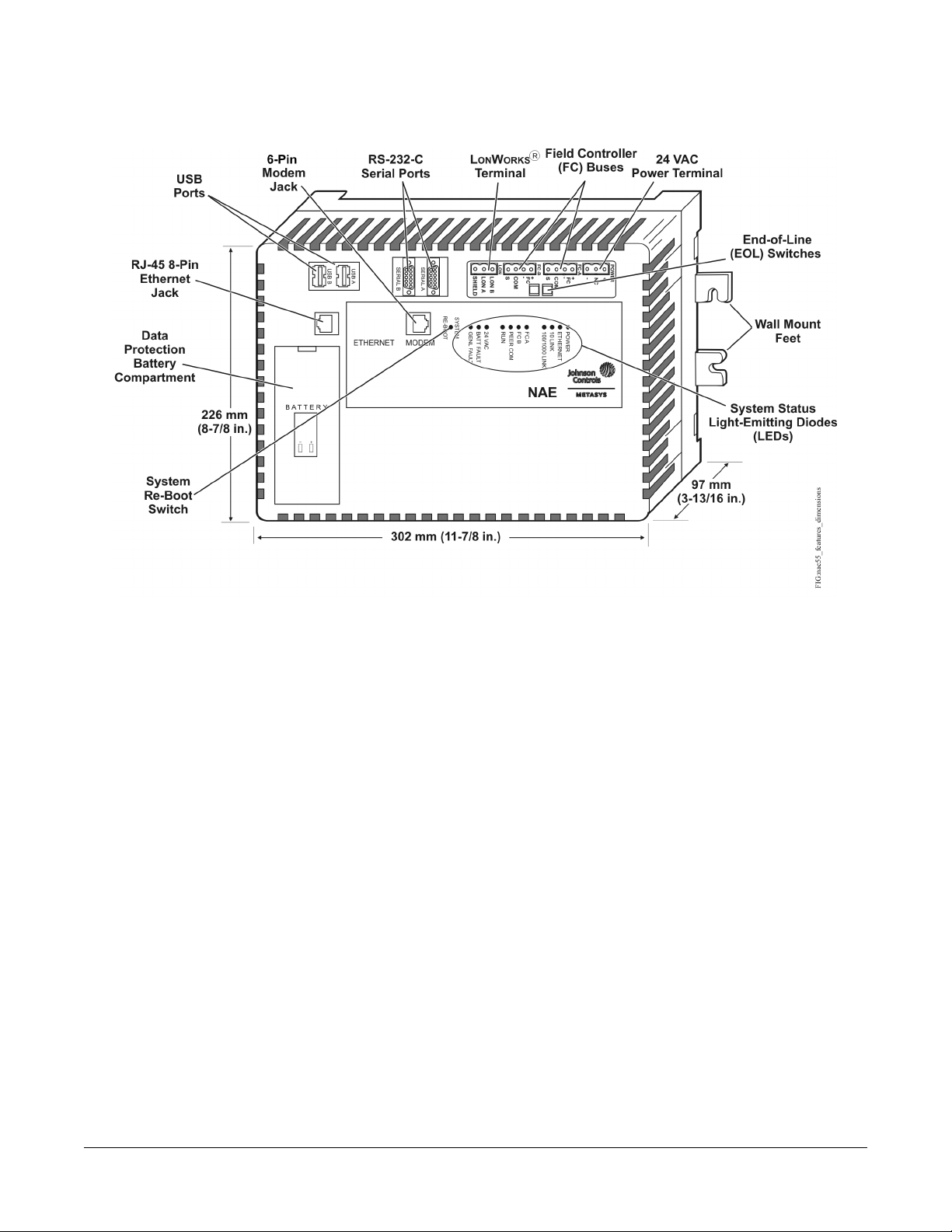
Dimensions
Figure 1: NAE55 Showing Dimensions, mm (in.), Physical Features, and Mounting Orientation
Note: The features shown in Figure 1 may or may not be present, depending on the NAE55/NIE55 model. See
Ordering Information for a list of features available on the NAE55/NIE55 models.
2NAE55/NIE55 Installation Instructions
Page 3
Mounting
Location Considerations
Follow these guidelines when mounting an NAE55:
• Ensure that the mounting surface can support the
NAE55 and any user-supplied enclosure.
•
Mount the NAE55 in the proper orientation (Figure
4).
• Mount the NAE55 on an even surface in wall mount
applications whenever possible. If you must mount
the NAE55 on an uneven surface, be careful not to
crack the wall mount feet or housing when tightening
the screws. Use shims or washers to mount the unit
securely on the mounting surface.
• Mount the NAE55 in areas free of corrosive vapors
and observe the environmental limitations listed in
the Technical Specifications section.
• Do not mount the NAE55 on surfaces that are prone
to vibration, such as duct work, or in areas where
electromagnetic emissions from other devices or
wiring can interfere with NAE55 communication.
• Allow sufficient space for running cable and wire,
making terminal connections, and accessing battery
compartment (Figure 2).
• Do not mount the power supply below the NAE55.
On panel or enclosure mount applications, observe these
additional guidelines:
• Do not install the NAE55 in an airtight enclosure.
• Mount the NAE55 so that the enclosure wall or the
transformer does not obstruct ventilation of the NAE55
housing.
Each NAE55 application is different, and no general
guidelines can be given about the heat dissipating devices
that may be mounted in an enclosure with the NAE55.
Monitor the NAE55 processor temperature for each
application to determine the acceptable combinations of
devices and proper mounting location for your specific
application.
Important: Do not add any devices to an enclosure with
an NAE55 that could cause the temperature
of the NAE55 processor to exceed 70˚C
(158˚F). View the NAE55’s CPU
Temperature value on the NAE55’s
Diagnostic tab on the Metasys® Site
Management Portal. See Technical
Specifications for ambient condition
requirements, and refer to the
Troubleshooting section of the NAE
Commissioning Guide (LIT-1201519) for
additional information.
Mounting the NAE55
Wall Mount Applications
To Mount the NAE55 on a vertical surface:
1. Mark the location of the four wall mount feet on the
wall using the dimensions in Figure 3 and an
orientation shown in Figure 4, or hold the NAE55 up
to the wall and mark the hole locations.
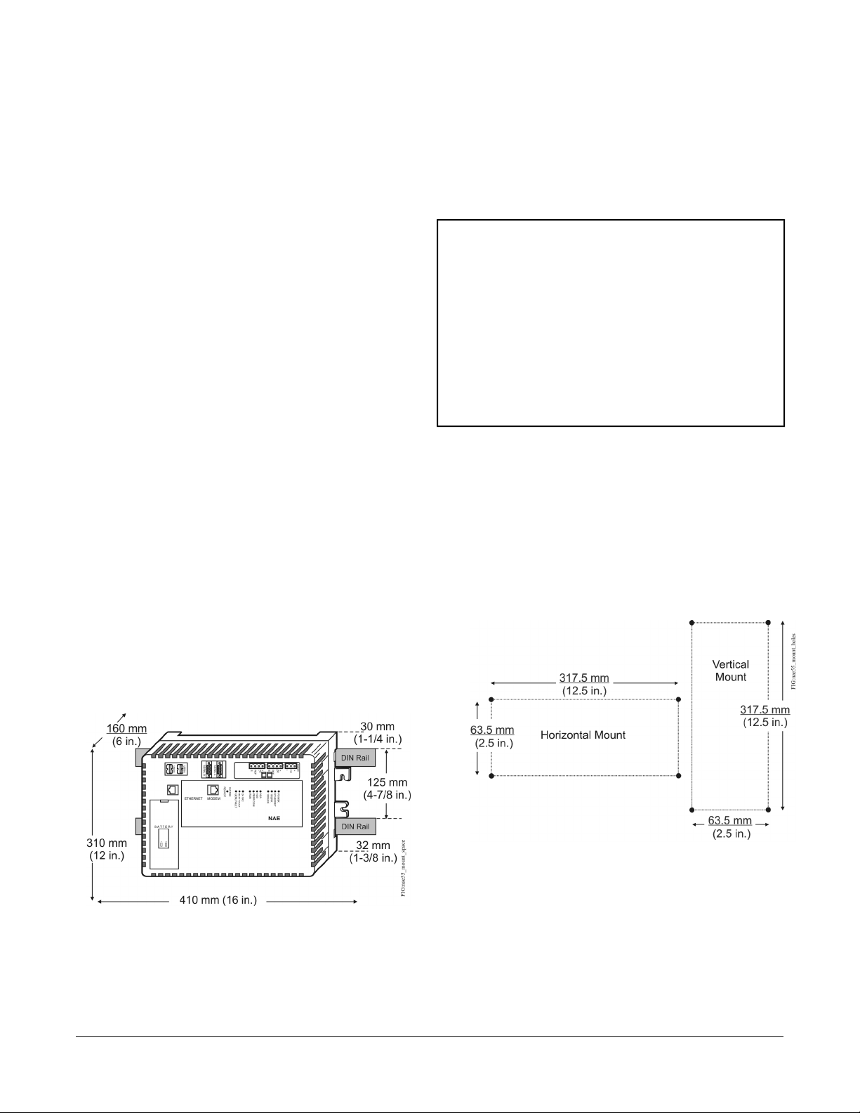
Figure 3: Mounting Screw Hole Dimensions,
mm (in.)
Figure 2: NAE55 DIN Rail Mount Dimensions and
Mounting Space Requirements, mm (in.)
2. Drill holes in the wall at the marked locations.
3. Insert appropriate wall anchors in all four holes (if
necessary) and insert the screws into the top two
holes. Leave enough space between the wall surface
and the screw head for the wall mount feet.
4. Hang the NAE55 on the screws with the top wall
mount feet for horizontal wall mount applications. Hold
the NAE55 in place for vertical application.
3NAE55/NIE55 Installation Instructions
Page 4
Note: The wall mount feet are designed to make
mounting easier. When the NAE55 is wall
mounted in the BEST (horizontal) orientation,
you can hang the NAE55 on the screws with
the upper two mount feet.
5. Insert the screws into the lower two wall mount feet
and holes and carefully tighten all of the screws.
Important: Do not overtighten the mounting screws.
Overtightening the screws can crack the
NAE55 wall mount feet or housing.
DIN Rail Mount Applications
To mount the NAE55 on DIN rails:
1. Mount two DIN rails horizontally, so they are 125 mm
(4.9 in.) apart on centers (Figure 2).
2. Snap the DIN clips on the bottom of the NAE55 to the
outward position.
3. Hang the NAE55 on the DIN rail hooks on the back
of the NAE55.
Press the DIN clips back into position to secure the unit
on the DIN rails.
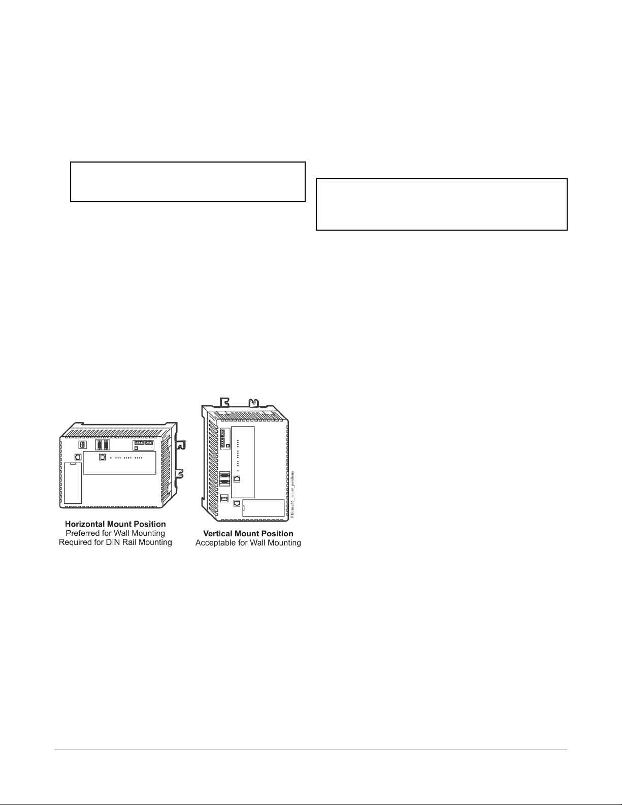
Figure 4: Required Orientations for NAE55 Wall Mount
Applications
Wiring
Power Supply, Network, and Communication Connections
See Figure 1 for the location of the power supply terminal,
network communication terminals, Ethernet jack, and
modem jack.
Power Supply
Important: Install the data protection battery before
applying 24 VAC power to the NAE55. See
the Installing the Data Protection Battery
section.
In North America, use a Class 2, 24 VAC power supply
with a 50 VA minimum output. Outside North America,
use a 24 VAC Safety Extra-Low Voltage (SELV)
transformer at the appropriate rating. The minimum input
voltage for the NAE55 to operate properly is 20 VAC.
See the Technical Specifications section.
Use a dedicated power supply to the NAE55 only. Do not
connect any other loads to the power supply. Additional
loads may cause noise interference.
FC Bus Terminal Block
The two Field Controllers (FCs) Bus connections on the
MS-NAE55xx-x models are 4-pin removable, keyed
terminal blocks labeled FC A and FC B.
To remove the NAE55 from the DIN rails:
1. Snap the DIN clips on the bottom of the NAE55 to the
outward position.
2. Lift the NAE55 off the DIN rails.
Enclosure Mount
To mount the NAE55 in an enclosure:
1. Mount the enclosure per the manufacturer’s
instructions.
2. Mount the NAE55 in the enclosure following the
guidelines in the Location Considerations and
Mounting the NAE55 sections of this document.
Note: MS-NIE55xx-x models (NIE55s) do not have FC
Bus terminal blocks or LONWORKS® network
terminal blocks.
The FC bus connections are optically isolated RS-485
ports with keyed 4-position terminal blocks that
communicate at 9.6k, 19.2k, 38.4k, or 76.8k baud. Use
an FC Bus port to integrate an N2 network or a BACnet®
Master-Slave/Token-Passing (MS/TP) FC Bus trunk into
the Metasys system.
Note: N2 and BACnet MS/TP Buses have different
protocols and network requirements. Do not
connect N2 and MS/TP devices to the same FC
Bus port.
The Shield (SHD) connections on the FC terminal blocks
are not connected to any earth ground connection. The
FC A and FC B terminal blocks are not interchangeable.
LONWORKS Network Terminal Block
The LONWORKS TP/FT-10 network connection on the
MS-NAE552x-2 models (only) is a 3-wire removable,
keyed terminal block. The SHD connection on the
LONWORKS network terminal block is an isolated terminal
and is not connected in the NAE552x. Use the LONWORKS
terminal block to connect LONWORKS networks to the
NAE552x.
4NAE55/NIE55 Installation Instructions
Page 5
Computer Serial Ports
The RS-232-C serial ports on the NAE55 are for direct
connection using a standard 9-pin female Data Terminal
Equipment (DTE) to 9-pin female DTE null modem cable.
The NAE55 serial ports do not support external modems.
The RS-232-C serial ports are labeled RS232C A and
RS232C B (Figure 1).
Use the RS232C A port to connect directly to a computer
serial port to browse to the NAE55. Use this port only for
establishing a Point-to-Point Protocol (PPP) network
connection. Refer to the Metasys System Extended
Architecture Direct Connection and Dial-Up Connection
Application Note (LIT-1201639).
Important: Do not apply 24 VAC power to the NAE55
before installing the data protection battery.
See the Installing the Data Protection
Battery section in this document.
Important: Use copper conductors only. Make all wiring
in accordance with local, national, and
regional regulations.
Important: The NAE55 is a low-voltage (<30 VAC)
device. Do not exceed the NAE electrical
ratings. Applying high voltage to the NAE
may result in permanent damage to the NAE
and void any warranties.
Use the RS232C B port to connect with a VT100 terminal
or computer using a VT100 terminal emulator because
the RS232C B port outputs the device IP address. Use
this port only to obtain the NAE55 IP address at startup.
Refer to the NAE Commissioning Guide (LIT-1201519).
Universal Serial Bus (USB) Ports
The two USB ports labeled USB A and USB B are both
configured as masters and are independent of each other.
Use the USB A port to connect an optional external
modem. Refer to the NAE Commissioning Guide
(LIT-1201519) for more information on external modems.
Ethernet Port
The Ethernet port, labeled ETHERNET, is an 8-pin RJ-45
network port for connecting the NAE55 to Ethernet
networks. NAE55 engines can connect to Ethernet
networks at 10 Mbps, 100 Mbps, or 1 Gbps.
On MS-NIE55xx-x models, use the Ethernet port for
migration of N1 communications. Refer to the N1
Migration with the NIE Technical Bulletin (LIT-1201535).
Optional Internal Modem
MS-NAE55x1-x and MS-NIE55x1-x models have an
internal modem and a 6-pin RJ-12 modular jack labeled
MODEM. Connect a standard phone line plug and cable
to the to use the internal modem.
For information on commissioning an internal modem,
refer to the NAE Commissioning Guide (LIT-1201519).
Wiring the NAE55/NIE55
Mount the NAE55 securely before wiring it. Follow these
guidelines when wiring the NAE55:
Important: Do not apply 24 VAC power to the NAE
before completing and checking
connections. Short circuits or improperly
connected wires may result in permanent
damage to the equipment.
Important: Do not remove the terminal block keys. The
terminal block plugs and the terminal
sockets are keyed to fit together in the
correct configuration only.
Important: Prevent any static electric discharge to the
NAE. Static electric discharge can damage
the NAE and void any warranties.
• Route the supply power wires and communication
cables at least 50 mm (2 in.) away from the vent slots
in the sides of the NAE55 housing.
• Provide slack in the wires and cables. Keep cables
routed neatly around the NAE55 to promote good
ventilation, LED visibility, and ease of service.
Note: Ensure that the building automation network wiring
meets the specifications, rules, and guidelines in
the Wiring Considerations and Guidelines for
Network Integrations section.
To wire the NAE55:
1. Connect the Ethernet cable to the RJ-45, 8-pin
Ethernet port shown in Figure 1.
2. Connect the Building Automation System (BAS)
network cables to the appropriate ports.
• For N2 or MS/TP networks, connect the 3-wire
bus cable to one of the removable 4-terminal plugs
labeled FA A or FC B (Figure 5).
• For LONWORKS compatible networks, connect the
2-wire cable from the LONWORKS network trunk to
th removable 3-terminal plug labeled LON (Figure
6).
Note: If an N2 Bus or MS/TP Bus is connected
to the NAE55, you must set the NAE55
EOL switches to the proper positions. See
the Setting the End-of-the-Line Switches
section.
5NAE55/NIE55 Installation Instructions
Page 6

3. If using a modem, connect a telephone line to the
modem port or connect an external modem to the
USB A as necessary.
Figure 5: FC Bus Terminal Block and Wiring
Connections
Figure 6: LONWORKS Network Terminal Block
and Wiring Connections
Figure 7: 24 VAC Supply Power Wiring
4. Make connections to the RS-232 serial ports (if
necessary).
5. Connect the 24 VAC supply power wires from the
transformer to the removable power terminal block
plug (Figure 7).
Power supply wire colors may be different on transformers
not manufactured by Johnson Controls. Follow the
transformer manufacturer’s instructions and the project
installation drawings.
The 24 VAC power should be connected to all network
devices so transformer phasing is uniform across the
devices. Powering network devices with uniform 24 VAC
supply power phasing reduces noise, interference, and
ground loop problems.
The NAE55 does not require an earth ground connection.
6NAE55/NIE55 Installation Instructions
Page 7

Wiring Considerations and Guidelines for Network Integrations
Table 1: NAE Ethernet Network Rules
Category
1
Refer to the N1 Ethernet/IP Network Technical Bulletin (LIT-6360175) for recommended parts and part numbers.
Rules/Maximums Allowed
Star topology with network hubs/switchesGeneral
Maximum of 100 devices can be connected to one site in the Metasys network.Number of Devices
2,000 m (6,600 ft) for plastic/glass fiber optic with external adapterLine Length and Type
10/100 BaseT: 100 m (330 ft) CAT5 cable
1000 BaseT: 100 m (330 ft) CAT5E cable
For 10/100/1000 BaseT, no line terminators allowed.Terminations
Table 2: Guidelines for BACnet Protocol MS/TP Network Topology
Rules/Maximums AllowedCategory
MS-NAE55xx-x models (only) support up to two MS/TP Bus trunks, daisy chain topology only.General
Number of Devices
Line Length and Type
Cable Type
Terminations
1
1001devices per Field Controller (FC) Bus with no more than two repeaters between NAE55 and
any device and a maximum of 50 devices between repeaters
1,500 m (5,000 ft)1cable without a repeater
4,500 m (15,000 ft) cable from NAE55 to the farthest FC Bus device (three bus segments of 1,500
m [5,000 ft] each, separated by repeaters)
2,000 m (6,600 ft) between two fiber modems
Stranded 0.6 mm (22 AWG) 3-wire twisted, shielded cable is recommended.
Stranded 0.6 mm (22 AWG) shielded 4-wire (two twisted-pairs) shielded cable is acceptable.
Note: The + and - bus leads should be a twisted pair. On applications using 4-wire (two
twisted-pairs) cable, isolate and insulate unused conductor. Refer to the MS/TP
Communications Bus Technical Bulletin (LIT-12011034) for more information.
Two FC devices with End-of-Line (EOL) switches in the ON position, one at each end of each FC
Bus segment
1
1 If TEC Thermostat Controllers or third-party devices are used on the FC Bus, the maximum total number of devices is 64 and
the maximum length is 1,219 m (4,000 ft).
2
Refer to the MS/TP Communications Bus Terminal Bulletin (LIT-12011034) for information on cable types and lengths.
Table 3: Guidelines for N2 Network Topology
Rules/Maximums AllowedCategory
MS-NAE55xx-x models (only) support up to two N2 Bus trunks.General
Only daisy-chained N2 devices (with maximum stub length of 3 m [10 ft] to any device)
Number of Devices
MS-NAE551x-x models (only) support up to 100 N2 devices per N2 Bus, with no more than two repeaters
between NAE55 and any N2 device and a maximum of 50 devices between repeaters.
1,500 m (5,000 ft) twisted pair cable without a repeaterLine Length and Type
4,500 m (15,000 ft) twisted pair cable from NAE55 and the farthest N2 device (three segments of 1,500
m [5,000 ft] each, separated by repeaters)
2,000 m (6,600 ft) between two fiber modems
7NAE55/NIE55 Installation Instructions
Page 8

Table 3: Guidelines for N2 Network Topology
Rules/Maximums AllowedCategory
Cable
Terminations
Solid or stranded 1.5 mm (18 AWG) 3-wire is recommended.
Solid or stranded 0.6 mm (24 AWG) larger 3-wire or 4-wire (two twisted-pairs) is acceptable.
Note: The + and - bus leads should be a twisted pair. On applications using 4-wire (two twisted-pairs)
cable, isolate and insulate unused conductor.
Preferred Termination Configuration: Two N2 devices with EOL switches in the ON position, one at
each end of each N2 Bus segment
Minimally Required Termination Configuration: At least one N2 device with an EOL switch in the ON
position somewhere on each N2 Bus segment
Table 4: Guidelines for LONWORKS Network Bus Topology
Cable Type
Maximum Segment Length with
FTT10 Devices Only
1 For the bus topology, the maximum length stub cable is 3 m (10 ft), and the stub lengths must be calculated into the overall
segment length.
Maximum Segment Length with
FTT10 and/or LPT10/11 Devices
2,200 m (7,200 ft)2,700 m (8,850 ft)Belden® 85102 Cable
2,200 m (7,200 ft)2,700 m (8,850 ft)Belden 8471 Cable
1,150 m (3,770 ft)1,400 m (4,600 ft)Level IV 22 AWG
750 m (2,460 ft)900 m (2,950 ft)JY (St.) Y 2 x 2 x 0.8
Table 5: Guidelines for LONWorks Network Free Topology
Maximum Node-to-Node DistanceCable Type
Maximum Segment Length with
FTT10 and/or LPT10/11 Devices
500 m (1,640 ft)500 m (1,640 ft)Belden 85102 Cable
500 m (1,640 ft)500 m (1,640 ft)Belden 8471 Cable
500 m (1,640 ft)400 m (1,300 ft)Level IV 22 AWG
500 m (1,640 ft)320 m (1,050 ft)JY (St.) Y 2 x 2 x 0.8
Table 6: Maximum Number of Devices per LONWORKS Network Segment
Maximum AllowedDevice Type
FTT10 Nodes Only
Mixed FTT10 and LPT-10/11 Nodes
Terminators
1 Each NPT10/11 channel segment (between repeaters) requires its own power supply. Other factors, such as power consumption
of individual LPT10/11 devices, may limit a segment to fewer devices.
2 The MS-NAE552x-x models that support LONWORKS Network trunks do not have an internal network terminator.
2
1
64 nodes if repeaters are not used; 255 nodes if repeaters are
used
([FTT10 x 2] + LPT10/11) < 128
Maximum of 1 per segmentPhysical Layer Repeaters
2 bus type EOL terminators required (NU-EOL202-0)Bus Topology
1 free topology terminator required (NU-EOL203-0)Free Topology
8NAE55/NIE55 Installation Instructions
Page 9

Setup and Adjustments
Installing the Data Protection Battery
Important: Do not apply 24 VAC power to the NAE55
before installing the data protection battery.
To install the data protection battery:
1. Remove the battery from its packaging. Remove the
battery cover on the NAE55 to expose the battery
compartment (Figure 1).
2. Carefully plug the NAE55 battery connector from the
battery compartment into the connector on the battery
cable (Figure 9).
3. Place the battery into the compartment (Figure 9).
4. Slide one end of the battery strap into the hole on the
opposite side of the strap (Figure 9), and loop the
strap tightly around the battery to minimize battery
movement.
5. Replace the cover of the battery compartment.
6. Apply 24 VAC power to the NAE55 immediately.
Important: The data protection battery must
maintain a small residual charge. The
battery ships from the factory with a
small residual charge. You should
connect 24 VAC power to the NAE55
immediately after connecting the battery
to ensure that the battery does not
completely lose its charge, which may
damage the battery.
Note: The 24 VAC power to the NAE55 charges the
data protection battery. At initial startup, the
battery requires a charging period of at least
2 hours before it supports data protection if
power fails. Maximum protection (up to three
consecutive power failures without recharging
time) requires a 24-hour charging period.
Setting the End-of-the-Line Switches
The network devices at each end of an FC Bus segment
must be set as network terminated devices. The NAE55
has two EOL switches (one for each FC Bus) that enable
you to set the NAE55 as a network terminated device on
the bus.
To set an NAE55 as an FC Bus terminated device,
position the switch on the EOL switch block to the ON
position (Figure 8).
Figure 8: FC Bus EOL Switch in the Factory Default
ON (Up) Position
Note: The NAE55 is shipped with the EOL switches for
both FC Buses in the initial factory position, ON
(Figure 8). If the NAE55 is not a terminated device
on the FC Bus, reposition the switch on the EOL
switch block to the Off (down) position.
Set the EOL switches appropriately for the FC A and FC
B buses. The NAE55 follows the same rules as other
switch-terminating devices listed in the Setting
Terminations sections of the N2 Communications Bus
Technical Bulletin (LIT-636018) and the MS/TP
Communications Bus Technical Bulletin (LIT-12011034).
Powering on the NAE55
After applying 24 VAC power, the NAE55 requires
approximately 3 minutes to start up and become
operational. See the LED Test Sequence at Startup
section.
Startup is complete and the NAE55 is operational when
the (green) RUN LED is On steady and the (red) GEN
FAULT LED is Off. See Figure 10 for LED locations.
Disconnecting Power from the NAE55
Important: The data protection battery must be installed
and charged before disconnecting the 24
VAC supply power.
The 24 VAC supply power is disconnected from the
NAE55 by removing the terminal block plug from the
power terminal port on the NAE55 (Figure 7).
When the 24 VAC supply power to the NAE55 is
disconnected or lost, the NAE55 is nonoperational. The
POWER LED (Figure 10) remains On, and the data
protection battery continues to power the NAE55 for
approximately 1 to 3 minutes so that volatile data can be
backed up in nonvolatile memory. The POWER LED goes
Off when the data backup is completed.
9NAE55/NIE55 Installation Instructions
Page 10

Figure 9: NAE55 and NAE55 Data Protection Battery
Troubleshooting
LED Status Indicators
The NAE55 has LEDs to indicate power and
communication status. See Figure 10 and Table 7.
LED Test Sequence at Startup
During startup, the NAE55 automatically initiates an LED
test to verify the operational status of the LEDs.
Immediately after connecting supply power, the following
LED lighting sequence occurs:
1. The NAE55 emits one short beep, indicating that the
BIOS startup was successful.
2. The PEER COM, RUN, and GENL FAULT LEDs turn
on, indicating that the Operating System (OS) is
booting up. For NAE55 models, the FC A and FC B
LEDs also turn on.
3. The PEER COM, RUN, GENL FAULT LEDs, and the
FC A and FC B LEDs (on NAE55 models) shut off.
The RUN LED flashes to indicate that the NAE55
software is loading.
4. The LEDs display the operational status of the
NAE55. When the RUN LED goes On Steady, the
operating system and Metasys application are running
and the NAE55 is ready.
The total time to start up the NAE55 depends on the size
of the database and can take several minutes.
Figure 10: NAE55 with LED Designations
System Re-Boot Switch
The System Re-Boot switch (Figure 1) forces a manual
restart of the NAE55 processor. All data changes made
to the system since the last time the NAE55 saved data
are lost on restart, including alarm, trend, and audit trail
data.
Note: Press the System Re-Boot switch only if the
NAE55 fails to respond and cannot be accessed
by any user device. Do not press the System
Re-Boot switch unless you have tried other
reasonable means to fix the problem.
Table 7: NAE55 LEDs Designation, Normal Status, Description, and Other Conditions
Descriptions/Other ConditionsNormalLED
On SteadyPOWER (Green)
FlickerETHERNET (Green)
On Steady = Unit is getting power from either the battery or 24 VAC power. Also
see the 24 VAC LED. Off Steady = Unit is shut down.
Flicker = Data is transferring on the Ethernet connection. Ethernet traffic is general
traffic (may not be for the NAE55).
Off Steady = No Ethernet traffic, probably indicates a dead Ethernet network or
bad Ethernet connection.
On Steady = Ethernet connection is established at 10 Mbps.On Steady10/LINK (Green)
10NAE55/NIE55 Installation Instructions
Page 11

Table 7: NAE55 LEDs Designation, Normal Status, Description, and Other Conditions
Descriptions/Other ConditionsNormalLED
On Steady (Green) = Ethernet connection is established at 100 Mbps.
On Steady (Yellow) = Ethernet connection is established at 1,000 Mbps.
On Steady = Controllers are defined to FC A (FC Bus 1 or N2 Trunk 1) in the
NAE55, but none are communicating (NAE55 transmitting only). Flicker = Normal
communications; FC A port is transmitting and receiving data. Flickers are generally
in sync with data transmission but should not be used to indicate specific
transmission times.
Off Steady = No field controllers are defined to FC A (FC Bus 1 or N2 Trunk 1) in
the NAE55.
On Steady = Controllers are defined to FC B (FC Bus 2 or N2 Trunk 2) in the
NAE55, but none are communicating. (NAE55 transmitting only) Flicker = Normal
communications; FC B port is transmitting and receiving data. Flickers are generally
in sync with data transmission but should not be used to indicate specific
transmission times.
Off Steady = No field controllers are defined to FC B (FC Bus 2 or N2 Trunk 2) in
the NAE55.
Flicker = Data traffic between NAEs. For an NAE55 that is not a Site Director, this
LED indicates regular heartbeat communications with the Site Director. For a Site
Director NAE55, flashes are more frequent and indicate heartbeat communications
from all other NAE devices on the site. For a single NAE55 on a network without
an Application and Data Server (ADS), there is no flicker.
On Steady = NAE55 software is running.
On 1 second, Off 1 second = NAE55 software is in startup mode.
On 0.5 seconds, Off 0.5 seconds = NAE55 software is shutting down.
Off Steady = Operating system is shutting down or software is not running.
On Steady = 24 VAC power is present.
Off Steady = Loss of 24 VAC power. In the Off Steady condition, the NAE55 can
be running on battery power. Also see the POWER LED.
On Steady = Battery fault. Replace the battery. Battery is not connected or cannot
be charged. The BATT FAULT LED may remain On for up to 24 hours after initially
powering on the NAE55. If the BATT FAULT LED remains on longer than 48 hours
after initially powering on the NAE55, check the battery connection or replace the
battery.
On Steady = General Fault. Fault conditions are user configurable in software.
Preconfigured fault conditions include excessive Central Processing Unit (CPU),
flash or memory use, excessive CPU or Printed Wire Board (PWB) temperature,
or Battery Fault. In normal operation, the GENL FAULT LED stays on steady for
the first half of the startup sequence.
(Green/Yellow)
(NIE55 models do not
have FC Bus terminals.)
(NIE55 models do not
have FC Bus terminals.)
PEER COMM (Green)
On Steady100/1000 LINK
FlickerFC A (Green)
FlickerFC B (Green)
Varies (see next
column)
On SteadyRun (Green)
On Steady24 VAC (Green)
Off SteadyBATT FAULT (Red)
Off SteadyGENL FAULT (Red)
Repair Information
If you replace an NAE55 for any reason or add a new
NAE55 to a site, you must update the site registration to
ensure that the new NAE55 is recognized and able to
communicate. Refer to the Replacing an NAE section in
the NAE Commissioning Guide (LIT-1201519) for
information on replacing an NAE and configuring the new
NAE to communicate in a Metasys system site.
Except for replacing the data protection battery, the
NAE55 cannot be repaired in the field. If the NAE55 fails
to operate, it must be replaced.
Batteries removed from this device must be recycled or
disposed of in accordance with local, national, and
regional regulations. Only trained technicians or qualified
building maintenance personnel should service Johnson
Controls products.
11NAE55/NIE55 Installation Instructions
Page 12

Ordering Information
Table 8: NAE55 Ordering Information
Number
MS-NAE55xx-x (Base
Features of Each
NAE55)
MS-NAE5510-1U
MS-NAE5511-2
MS-NAE5520-2
MS-NAE5521-2
MS-MULTENGSW-6
1
DescriptionProduct Code
NAE55 Network Automation Engines: Requires a 24 VAC power supply. Each model includes two
RS-232-C serial ports, two USB serial ports, two RS-485 ports, one Ethernet port, and one MS-BAT1010-0
Data Protection Battery. Supports up to 100 devices on each N2 or BACnet MS/TP trunk.
Supports two N2 or two BACnet MS/TP (RS-485) trunks (or one N2 trunk and one BACnet MS/TP trunk).MS-NAE5510-2
Supports two N2 or two BACnet MS/TP (RS-485) trunks (or one N2 trunk and one BACnet MS/TP trunk).
Note: This model is UL Listed, File S4977, UUKL 864 9th Edition Smoke Control Equipment. Refer to
the NAE55/NIE55 Installation Instructions (Part No. 24-10051-0) and the Metasys® System UL
864 9th Edition UUKL/ORD-C100-13 UUKLC Smoke Control System Technical Bulletin
(LIT-12011252)for detailed specifications, requirements and procedures for installing and operating
UUKL 864 Listed Metasys system devices.
Supports two N2 or two BACnet MS/TP (RS-485) trunks (or one N2 trunk and one BACnet MS/TP trunk);
includes an internal modem.
Supports a trunk and two N2 trunks or two BACnet MS/TP (RS-485) trunks (or one N2 trunk and one
BACnet MS/TP trunk). Supports up to 255 devices on the LONWORKS trunk.
Supports a LONWORKS trunk, and two N2 trunks or two BACnet MS/TP (RS-485) trunks (or one N2 trunk
and one BACnet MS/TP trunk); includes an internal modem. Supports up to 255 devices on the LONWORKS
trunk.
Contains ToggleTunnel utility for converting an NAE55/NIE55 to an NAE55 model with the N2 Tunneling
features enabled. Not for use with MS-NAE5510-OU or MS-NIE5510-OU.
1 Some models are also available in a Buy American version (add a G after the code number). For the European version, add
an E after the code number. For repair parts, add -702 after the code number.
Table 9: NIE55 Series Ordering Information
DescriptionProduct Code
Number
MS-NIE55xx-x (Base
Features of Each
NIE55)
1
NIEs : Requires a 24 VAC power supply. Each model includes two RS-232-C serial ports, two USB serial
ports, one Ethernet port, and one MS-BAT1010-0 Data Protection Battery.
Supports N1 network migrations.MS-NIE5510-2
Supports N1 network migrations, includes an internal modem.MS-NIE5511-2
Table 10: Accessories Ordering Information
DescriptionProduct Code
Number
MS-BAT1010-0
1 Some models are also available in a Buy American version (add a G after the code number). For the European version, add
an E after the code number. For repair parts, add -702 after the code number.
1
Replacement data protection battery for NAE55 and NIE models. Rechargeable gel cell battery with a
typical life of 3 to 5 years at 21°C (70°F).
Power transformer (Class 2, 24 VAC, 92 VA maximum output), with enclosureAS-XFR100-1
Power transformer (Class 2, 24 VAC, 92 VA maximum output), no enclosureAS-XFR010-1
12NAE55/NIE55 Installation Instructions
Page 13

Technical Specifications
Table 11: NAE55xx-2 and NIE55xx-2
Power Requirement
Data Protection Battery
Clock Battery
Memory
Network and Serial Interfaces
Housing
Dimensions(Height x Width x
Depth)
Compliance
Dedicated nominal 24 VAC, Class 2 power supply (North America), SELV power supply
(Europe), at 50/60 Hz (20 VAC minimum to 30 VAC maximum)
50 VA maximumPower Consumption
0 to 50°C (32 to 122°F); 10 to 90% RH, 30°C (86°F) maximum dew pointAmbient Operating Conditions
-40 to 70°C (-40 to 158°F); 5 to 95% RH, 30°C (86°F) maximum dew pointAmbient Storage Conditions
Supports data protection on power failure. Rechargeable gel cell battery: 12 V, 1.2 Ah, with
a typical life of 3 to 5 years at 21°C (70°F); Product Code Number: MS-BAT1010-0
Maintains real-time clock through a power failure. Onboard cell; typical life 10 years at 21°C
(70°F)
1.6 GHz Intel® Atom™ processor for MS-NAE55xx-2 modelsProcessor
4 GB Flash nonvolatile memory for operating system, configuration data, and operations data
storage and backup for MS-NAE55xx-2 models.
1 GB Synchronous Dynamic Random Access Memory (SDRAM) for operations datadynamic
memory for all models
Microsoft® Windows® Embedded Standard 2009Operating System
One Ethernet port; 10/100/1,000 Mbps; 8-pin RJ-45 connector
Two optically isolated RS-485 ports; 9,600, 19.2k, 38.4k, or 76.8k baud; pluggable and keyed
4 position terminal blocks (RS-485 terminal blocks available on NAE55 models only)
Two RS-232-C serial ports, with standard 9-pin sub-D connectors, that support all standard
baud rates
Two USB serial ports; standard USB connectors support an optional, user-supplied external
modem
Options: One telephone port for internal modem; up to 56 kbps; 6-pin RJ-12 connector One
LONWORKS port; FTT10 78 Kbps; pluggable, keyed 3-position terminal block (LONWORKS port
available on NAE552x-x models only)
Plastic housing with internal metal shield
Plastic material: ABS + polycarbonate; Protection: IP20 (IEC 60529)
On flat surface with screws on four mounting feet or on dual 35 mm DIN railMounting
226 x 332 x 96.5 mm (8.9 x 13.1 x 3.8 in.) including mounting feet
Minimum space for mounting: 303 x 408 x 148 mm (12.0 x 16.1 x 5.8 in.)
2.9 kg (6.4 lb)Shipping Weight
United States : UL Listed, File E107041, CCN PAZX, UL 916, Energy Management Equipment,
FCC Compliant to CFR47, Part 15, Subpart B, Class A
Canada: UL Listed, File E107041, CCN PAZX7, CAN/CSA C22.2 No. 205, Signal Equipment,
Industry Canada Compliant, ICES-003
Europe: CE Mark - Johnson Controls, Inc., declares that this product is in compliance with
the essential requirements and other relevant provisions of the EMC Directive 2004/108/EC.
Australia and New Zealand: C-Tick Mark, Australia/NZ Emissions Compliant
BACnet International: BACnet Testing Laboratories™(BTL) 35-2004 Listed BACnet Building
Controller (B-BC)
The performance specifications are nominal and conform to acceptable industry standard. For application at conditions
beyond these specifications, consult the local Johnson Controls® office. Johnson Controls, Inc. shall not be liable
for damages resulting from misapplication or misuse of its products.
13NAE55/NIE55 Installation Instructions
Page 14

507 E. Michigan Street, Milwaukee, WI 53202
Metasys® and Johnson Controls® are registered trademarks of Johnson Controls, Inc.
All other marks herein are the marks of their respective owners. © 2013 Johnson Controls, Inc.
Building Efficiency
www.johnsoncontrols.comPublished in U.S.A.
14NAE55/NIE55 Installation Instructions
 Loading...