

Page 1
NIE39/NIE49 Installation Instructions
MS-NIE39xx-2, MS-NIE49xx-2
(barcode for factory use only)
Part No. 24-10050-103, Rev. H
Software Release 9.0
Issued August 2017
Refer to the QuickLIT website for the most up-to-date version of this document.
Application
Important: NIEx9s are compatible with Metasys® system Release 7.0 and later. You may apply the dual trunk
integration feature to NIEx9s purchased prior to the current release by using the NIEx9 Driver Manager
tool. For information on how to apply the latest package and license files that support dual trunks, refer
to the NIEx9 Driver Manager Application Note (LIT-12011919).
The Network Integration Engine (NIE) 39 and 49 are web-enabled, Ethernet-based, supervisory devices that integrate
the Metasys Building Management System to other standard building management communication technologies.
Integrations include the BACnet® protocol, LONWORKS® network, N2 Bus protocol, Modbus®, Meter-Bus (M-Bus,
European Standard EN 1434-3), KNX, and other third party proprietary protocols for monitoring and supervising a
wide variety of HVAC, lighting, security, fire, electrical and thermal measuring and access control equipment.
For the Modbus and M-Bus protocols, one NIE39 or NIE49 can support two integrations: two Modbus, two M-Bus,
or one of each, significantly expanding the engine's flexibility. See Table 10 for a list of all supported dual trunk
applications.
Important: The NIEx9 is shipped with a license and driver for the communication protocol that was ordered. If you
re-image the engine, the license and driver are deleted and the engine is not able to communicate with
the required protocol. If you need to re-image the engine, use the NIEx9 Driver Manager first to preserve
the protocol driver and license file before you re-image. For details, refer to the NIEx9 Driver Manager
Application Note (LIT-12011919).
This document describes how to install an NIE39 or NIE49, which is referred to collectively as NIE, unless specified
otherwise. Figure 1 shows the components of the NIE.
Installation
Follow these guidelines when installing the NIE:
• Transport the NIE in the original container to minimize vibration and shock damage to the NIE.
• Verify that all the parts shipped with the NIE.
• Do not drop the NIE or subject it to physical shock.
• Do not open the NIE housing (except the data protection battery compartment). The NIE has no user-serviceable
parts inside.
Parts Included
• one NIE with removable terminal plugs
• one data protection battery (installed and connected when the NIE is shipped)
• one Installation Instructions sheet
Materials and Special Tools Needed
• three M4 (#8) fasteners appropriate for the mounting surface
• one 20 cm (8 in.) or longer piece of DIN rail and appropriate hardware for mounting the DIN rail
1NIE39/NIE49 Installation Instructions
Page 2
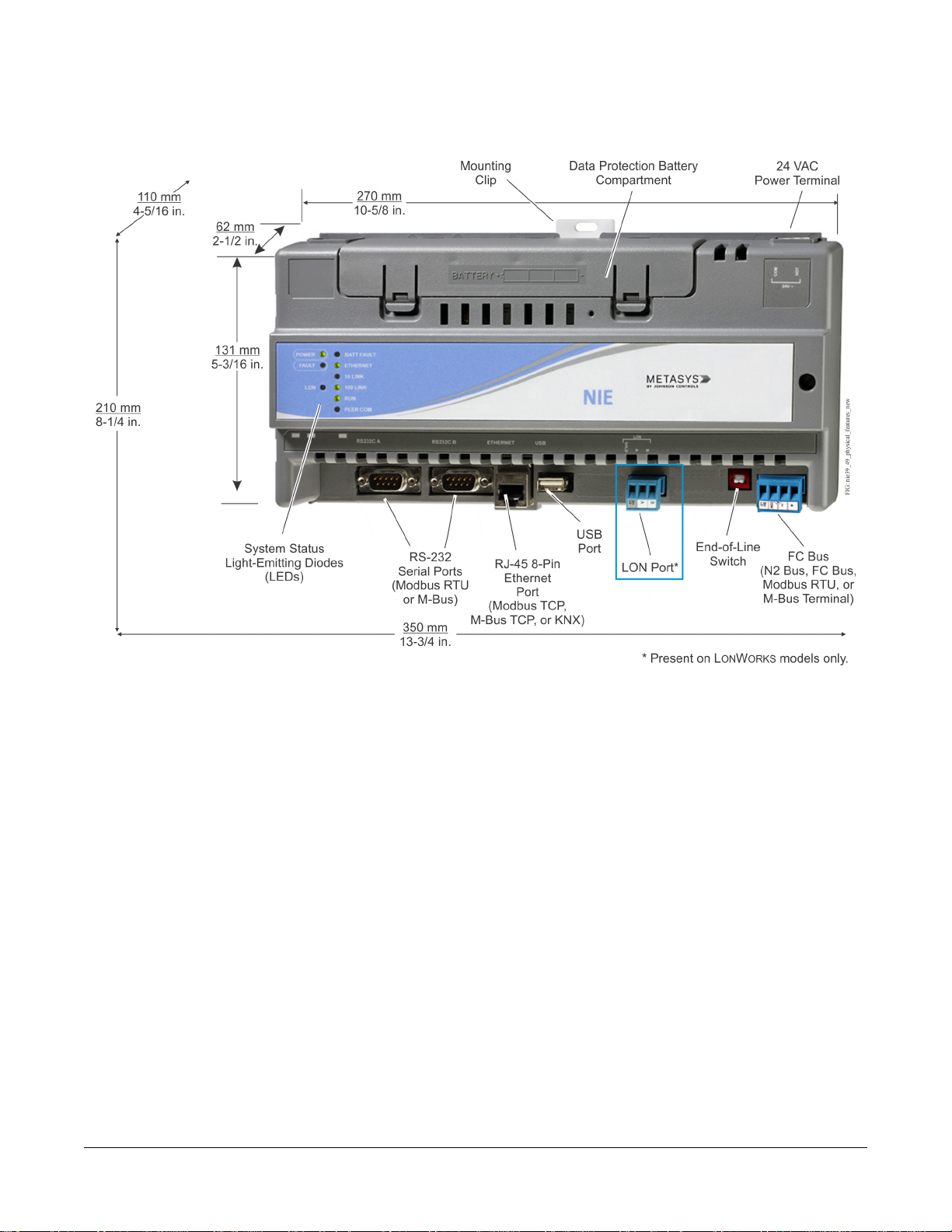
Dimensions and Physical Features
Figure 1: NIE Dimensions and Physical Features
Mounting
Location Considerations
Follow these guidelines when mounting an NIE:
• Ensure that the mounting surface can support the NIE and any user-supplied enclosure.
•
Mount the NIE in proper orientation (Figure 1).
• Mount the NIE on an even surface in wall mount applications whenever possible. If you must mount the NIE on
an uneven surface, be careful not to crack the mounting clips or NIE housing when tightening the screws. Use
shims or washers to mount the NIE evenly on the mounting surface.
•
Mount the NIE in areas free of corrosive vapors, and observe the environmental limitations listed in the Technical
Specifications section.
• Allow sufficient space for cable and wire connections and access to the data protection battery and End-of-Line
(EOL) switch (Figure 1).
• Do not mount the NIE where the ambient temperature may exceed 50°C (122°F).
• Do not mount the NIE on surfaces prone to vibration or in areas where electromagnetic emissions can interfere
with NIE communication.
• Do not obstruct the NIE housing ventilation holes.
• Do not mount power transformers below the NIE.
2NIE39/NIE49 Installation Instructions
Page 3
On applications where the NIE is mounted inside a panel or enclosure, follow these additional guidelines:
• Do not install the NIE in airtight enclosures.
• Do not install heat-generating devices in the enclosure with the NIE that may cause the ambient temperature to
exceed 50°C (122°F).
Mounting the NIE
Wall Mount Applications
Use the holes in the three mounting clips for wall mount applications.
To mount the NIE on a vertical surface:
1. Ensure that all three mounting clips are inserted into the back of the NIE housing, pulled outward, and snapped
firmly into the extended position (Figure 3).
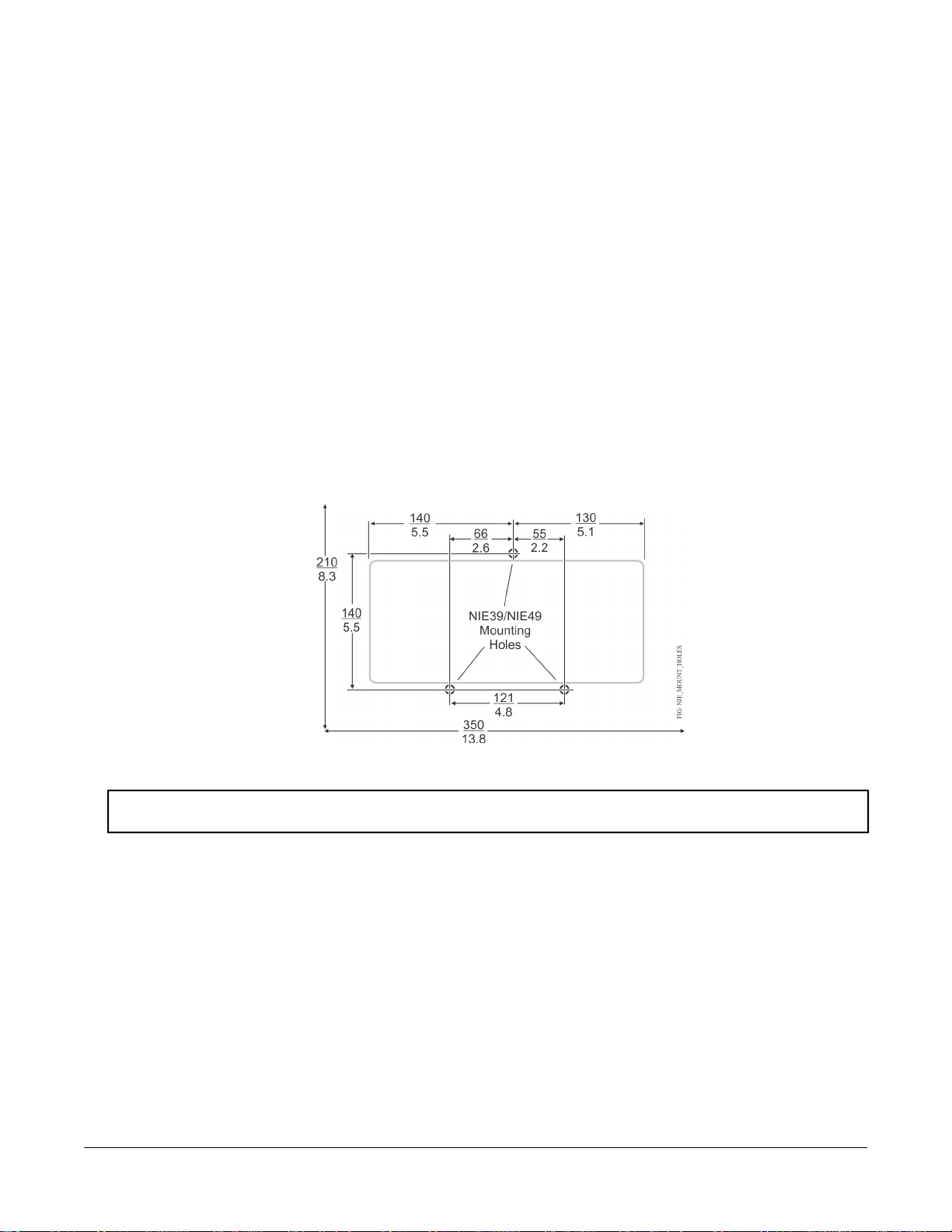
2. Mark the location of the three wall mount holes using the dimensions in Figure 2, or hold the NIE up to the wall
as a template and mark the locations.
3. Drill holes in the wall at the locations marked in Figure 2 and insert wall anchors (if necessary).
Figure 2: NIE Mounting Screw Hole Dimensions (mm/in.) and Mounting Area Requirements
4. Position the NIE, insert the screws through the holes in the mounting clips, and carefully tighten the screws.
Important: Do not overtighten the mounting screws. Overtightening the screws may damage the mounting
clips or the NIE housing.
DIN Rail Mount Applications
To mount the NIE on a DIN rail:
1. Securely mount a 20 cm (8 in.) or longer section of DIN rail horizontally and centered in the space.
2. Ensure that the bottom two mounting clips are pulled outward and snapped firmly into the extended position
(Figure 3).
3NIE39/NIE49 Installation Instructions
Page 4
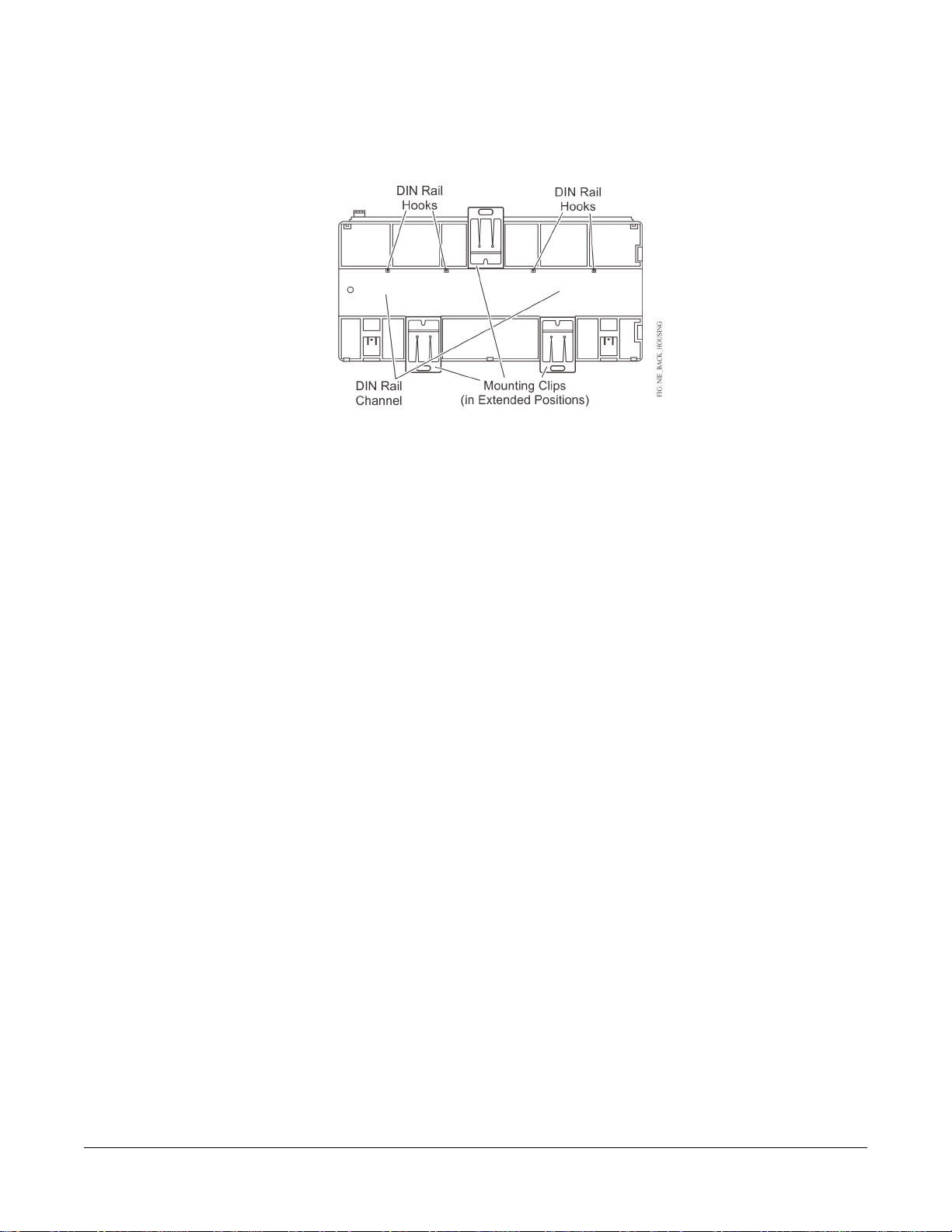
Figure 3: DIN Rail and Mounting Clip Features on the Back of an NIE
3. Hang the NIE by the DIN rail hooks (Figure 3) on the top track of the DIN rail, and position the NIE DIN rail
channel snugly against the tracks of the DIN rail.
4. Push the bottom mounting clips up to secure the NIE on the DIN rail tracks.
To remove the NIE from the DIN rail, snap the bottom DIN clips to the outward extended position, and carefully
lift the NIE off the DIN rail.
Enclosure Mount Applications
Mount the enclosure per the manufacturer’s instructions and mount the NIE in the enclosure following the guidelines
in the Location Considerations and Mounting the NIE sections.
Wiring
Power Supply, Network, and Bus Connections
See Figure 1 for the location of NIE ports, modular jacks, and terminal blocks.
Depending on the model, an NIE39/NIE49 supports either an MS/TP field bus trunk, an N2 Bus trunk, or a LONWORKS
network trunk. All models support two vendor integrations, such as two Modbus, two M-Bus, or one of each. Or if a
KNX integration is required, three KNX IP Gateways are supported for one NIE39/NIE49. See Table 10 for a list of
all supported dual trunk applications. The rules, guidelines, and wiring considerations for each type of network or
field bus application are provided in tables of this document.
Power Supply
In North America, the NIE requires a dedicated Class 2, 24 VAC, 25 VA minimum power supply. Outside North
America, use a 24 VAC safety extra-low voltage (SELV) transformer at the appropriate rating. The minimum input
voltage for the NIE to operate properly is 20 VAC. Maximum power consumption is 25 VA.
FC Bus Port
MS-NIE391x-x and MS-NIE491x-x models support one N2 Bus, one Master-Slave/Token-Passing (MS/TP) Bus,
one Modbus RTU trunk, or one M-Bus on the Field Controller (FC) Bus port. Connect the trunk to the 4-wire terminal
block plug labeled FC BUS. See Table 1 and Table 2 for more information on bus rules and bus device limits.
Note: BACnet® MS/TP, N2, Modbus RTU, and M-Bus are different protocols with different network requirements.
Do not intermix devices from different protocols to the same FC Bus connection.
4NIE39/NIE49 Installation Instructions
Page 5
FC Bus Modular Jack
The 6-pin modular jack labeled FC BUS is an FC Bus service port for MS/TP applications (only).
Note: Do not connect an N2 trunk to the 6-pin modular FC Bus jack.
Refer to the N2 Communications Bus Technical Bulletin (LIT-636018) or the MS/TP Communications Bus Technical
Bulletin (LIT-12011034) for additional information and guidelines on wiring devices on an N2 trunk or an MS/TP
trunk.
LON Port
MS-NIE392x-x and MS-NIE492x-x models support one LONWORKS network trunk. Connect a LONWORKS network
trunk to the 3-wire terminal block terminal labeled LON. The cable Shield (SHD) on the LON port is an open terminal
and is not connected in the NIE.
Serial Ports
The RS232C A and RS232C B serial ports (Figure 1) provide direct connection to a Modbus RTU or M-Bus network
using a standard 9-pin female data terminal equipment (DTE) to 9-pin female DTE null modem cable. Integration of
only one device is permitted.
If the RS232C A serial port is not used to integrate a vendor protocol, you can connect to a computer serial port to
browse to the NIE or to connect to a VT100 or a computer with a VT100 emulator and perform diagnostic procedures.
If the RS232C B serial port is not used to integrate a vendor protocol, you can use the port to connect to an external
modem. Refer to the Metasys®System Extended Architecture Direct Connection and Dial-Up Connection Application
Note (LIT-1201639) for more information.
USB Port
The port connects to an external flash drive that can store diagnostic information when the NIE is placed in diagnostic
mode. You can otherwise configure the USB serial port to use an optional, user-supplied external modem.
Ethernet Port
The Ethernet port, labeled ETHERNET, is an 8-pin RJ-45 network port (Figure 1) for connecting the NIE to Ethernet
networks. NIE39/49 engines can connect to Ethernet networks at 10 or 100 Mbps. Use this port for connecting a
Modbus TCP, M-Bus TCP, or KNX network.
Wiring the NIE
Important: Do not connect 24 VAC supply power to the NIE before finishing wiring and checking all wiring
connections. Short circuits or improperly connected wires may result in permanent damage to the
equipment.
Important: Use copper conductors only. Make all wiring in accordance with local, national, and regional regulations.
The NIE is a low-voltage (<30 VAC) device. Do not exceed the NIE electrical ratings.
Important: Do not remove the terminal block keys. The terminal block plugs and the terminal sockets are keyed
to fit together in the correct configuration only.
Important: Prevent any static electric discharge to the NIE. Static electric discharge can damage the NIE and void
any warranties.
Important: Make sure the building automation network wiring meets the specifications, rules, and guidelines in
the Power Supply, Network, and Bus Connections section in this document.
Mount the NIE securely before wiring the NIE. See the Mounting section.
5NIE39/NIE49 Installation Instructions
Page 6
Follow these guidelines when wiring an NIE:
• Route the supply power wires and communication cables at least 50 mm (2 in.) away from the vent slots on the
sides of the NIE housing.
• Provide slack in the wires and cables. Keep cables routed neatly around the NIE to promote good ventilation,
LED visibility, and ease of service.
Wiring the NIE for N2, MS/TP, Modbus RTU, or LONWORKS Protocol
1. Connect the Ethernet cable to the RJ-45, 8-pin Ethernet port on the NIE shown in Figure 1.
2. If using an external modem, connect the modem to USB A using the proper cable.
3. Connect the Building Automation System (BAS) network cables to the appropriate ports.
For an N2, MS/TP, or Modbus RTU network, connect the 3-wire bus cable to the removable 4-terminal blue
•
plug labeled FC Bus (Figure 4).
Note: If an N2 or MS/TP is connected to the NIE, you must set the NIE EOL switches to the proper positions.
See the Setting the End-of-Line Switch section.
• For LONWORKS compatible networks, connect the 2-wire cable from the LONWORKS network trunk to the
removable 3-terminal blue plug labeled LON (Figure 5).
Note: The LONWORKS network trunk is available on the NIE3920-x and NIE4920-x models only.
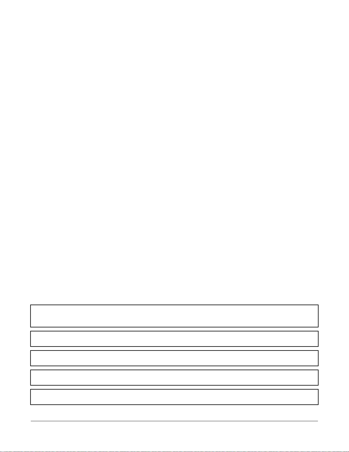
Figure 4: FC Bus Terminal Block and Wiring Connections
Figure 5: LONWORKS Network Terminal Block and Wiring Connections
4. For Modbus RTU Protocol using the RS232C A or RS232C B serial port, use a cable to connect the
RS-232/RS-485 converter to the RS232C A or RS232C B serial port on the NIE.
6NIE39/NIE49 Installation Instructions
Page 7
Note: The maximum cable length between devices connected though an RS-232 line depends on the baud
rate used. In general, it should not exceed 15 meters at 9600 baud.
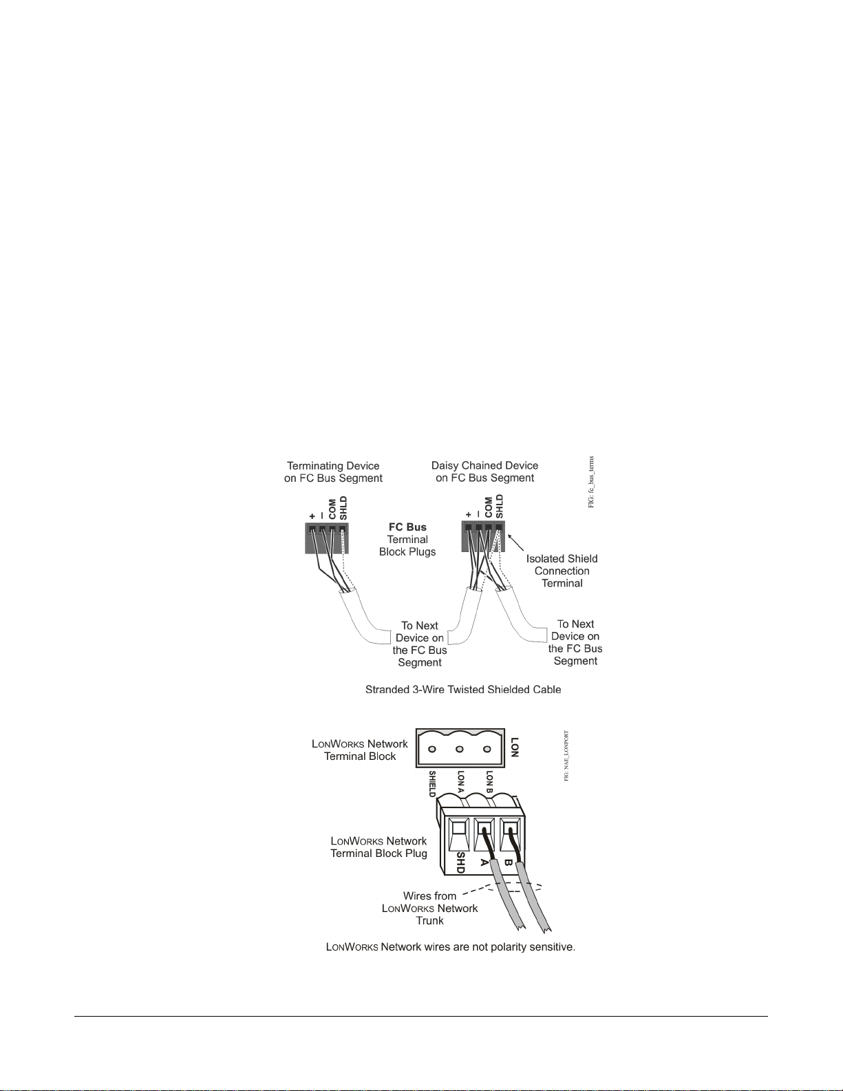
5. Wire from the RS-485 terminal on the converter to the RS-485 port on the vendor device (Figure 6). The RS-485
bus is a two-wire network.
a. Connect the converter's + A terminal to the device's + (or A) terminal.
b. Connect the converter's - B terminal to the device's - (or B) terminal.
c. If the device has a Signal Ground or Reference terminal, connect this to the converter's CG2 terminal.
Figure 6: Connection Between Converter and Device
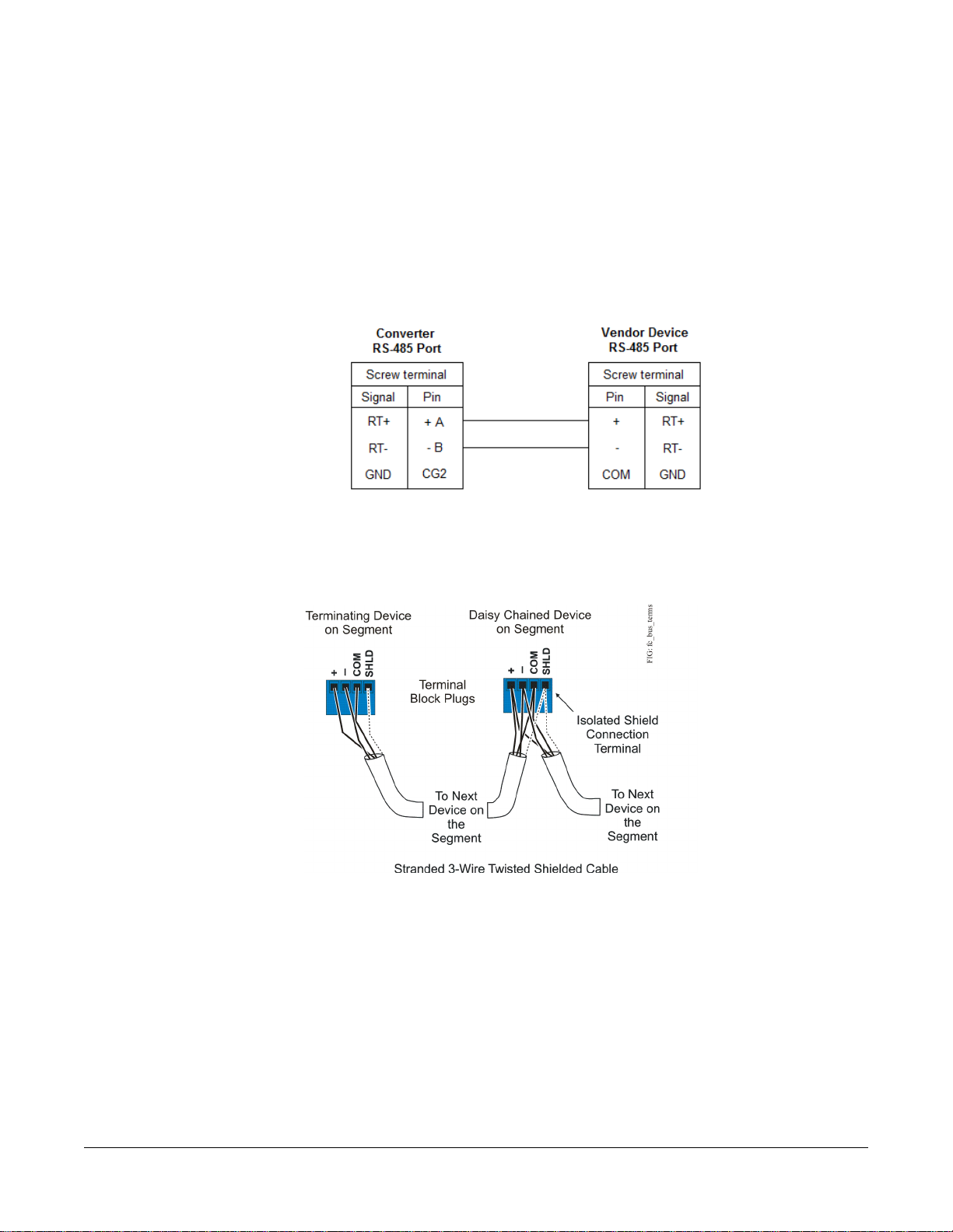
6. To add additional vendor devices, wire from one device to the next as shown in Figure 7. No more than two wires
may be connected to each terminal to ensure the daisy chain configuration. See Wiring Rules and Guidelines
for Network Integrations for the Modbus protocol.
Figure 7: Daisy Chained Devices
The completed wiring should look similar to Figure 8.
7NIE39/NIE49 Installation Instructions
Page 8

Figure 8: Modbus Wiring Detail Overview
7. Connect the 24 VAC supply power wires from the transformer to the removable power terminal block plug on
the NIE (Figure 9).
Figure 9: 24 VAC Supply Power Wiring
Note: Power supply wire colors may be different on transformers not manufactured by Johnson Controls. Follow
the transformer manufacturer’s instructions and the project installation drawings.
8. Connect the 24 VAC supply power wires from the transformer to the converter. No additional external power
adapter is required. Connect the hot and common wires as desired. The NIE does not require an earth ground
connection.
Note: The 24 VAC power should be connected to all network devices so transformer phasing is uniform across
the devices. Powering network devices with uniform 24 VAC supply power phasing reduces noise,
interference, and ground loop problems.
Wiring the NIE for M-Bus Protocol
1. Connect the Ethernet cable to the RJ-45, 8-pin Ethernet port shown in Figure 1.
2. Connect from the RS232C A or RS232C B serial port on the NIE to the RS-232 connecter of the level converter.
Wire to terminals GND, RxD, and TxD as shown in Figure 10.
3. Wire from the M- and M+ terminals on the level converter (Figure 10) to the meters using a free (star, tree, or
line) topology. Specific cabling can vary depending on the topology and site. See Wiring Rules and Guidelines
for Network Integrations.
8NIE39/NIE49 Installation Instructions
Page 9

Note: If the number of M-Bus unit loads or distances exceeds the specifications of a level converter, an M-Bus
repeater can be wired to the converter to increase the number of unit loads and distances. The converter
shown in Figure 10 is capable of handling up to 6 units loads, while other models can handle up to 100.
See NIE Ordering Information for a list of M-Bus devices.
4. Connect the 24 VAC supply power wires from the transformer to the removable power terminal block plug on
the NIE (Figure 9).
Note: Power supply wire colors may be different on transformers not manufactured by Johnson Controls. Follow
the transformer manufacturer’s instructions and the project installation drawings.
5. Connect the 24 VAC supply power wires from the transformer to the -/~ and +/~ terminals as shown in Figure
10.
Figure 10: M-Bus Level Converter
Wiring the NIE for KNX Protocol
1. Connect an Ethernet cable to the RJ-45, 8-pin Ethernet port shown in Figure 1.
2. Connect another Ethernet cable to the port on the front of the KNX gateway (Figure 11).
Note: Depending on the size of your network, you can use either a KNX Interface or Router as a gateway. The
Interface connects the NIE to a single KNX line, while the Router acts as both an Interface and a Line
Coupler over Ethernet to connect the NIE to the network, not to a single device.
9NIE39/NIE49 Installation Instructions
Page 10

Figure 11: KNX/IP Interface Router
3. For a single KNX line, wire from the red and black terminals on the gateway to the devices. For multiple KNX
lines, wire from the red and black terminals on each gateway to the devices on the same KNX line.
Note: Specific cabling can vary depending on the topology and site. See Wiring Rules and Guidelines for
Network Integrations.
4. Wire each KNX gateway to its own dedicated power supply on the KNX line.
Wiring Rules and Guidelines for Network Integrations
Table 1: MS/TP Bus Rules
Rules and Maximums AllowedCategory
One MS/TP Bus trunk supported per NIE (on NIE391x-x and NIE491x-x models only)General
Only daisy-chained MS/TP devices
Number of FC Devices
Supported
MS-NIE491x-x models support up to 1001MS/TP devices total on the FC Bus with no more than
two repeaters between an NIE49 and any device and a maximum of 50 devices between repeaters.
MS-NIE391x-x models support up to 501MS/TP devices total on the FC Bus with no more than
two repeaters between an NIE39 and any device and a maximum of 50 devices between repeaters.
1,500 m (5,000 ft) cable per bus segment without a repeaterBus Length
4,500 m (15,000 ft) cable from NIE to the farthest FC Bus device (three bus segments of 1,500 m
[5,000 ft] each, separated by repeaters)
2,000 m (6,600 ft) between two fiber modems
10NIE39/NIE49 Installation Instructions
Page 11

Table 1: MS/TP Bus Rules
Rules and Maximums AllowedCategory
Cable Type
1 If the TEC Thermostat Controllers or third-party MS/TP devices are connected to the FC Bus, the maximum total number of
MS/TP controllers on an FC Bus is 64 for NIE45 models and 32 for the NIE35 models. The maximum cable length per bus
segment is 1,219 m (4,000 ft) and the maximum total FC Bus length is 3,658 m (12,000 ft).
2
Refer to the MS/TP Communications Bus Technical Bulletin (LIT-12011034) for more information on alternative cable types
and lengths.
2
Stranded 0.6 mm (22 AWG) 3-wire twisted, shielded cable is recommended. Stranded 0.6 mm (22
AWG) 4-wire (two twisted-pairs) shielded cable is acceptable.
Note: The + and - bus leads should be a twisted pair. On FC Bus applications using 4-wire (two
twisted-pairs) cable, isolate and insulate unused conductor. Refer to the MS/TP Communications
Bus Technical Bulletin (LIT-12011034) for more information.
Two FC Bus devices with EOL switches in the ON position, one at each end of each FC Bus segmentTerminations
Table 2: N2 Bus Rules
Rules and Maximums AllowedCategory
MS-NIE391x-x and MS-NIE491x-x models (only) support one N2 Bus trunk.General
Only daisy-chained N2 devices (with maximum stub length of 3 m [10 ft] to any device)
Number of N2 Devices
Supported
Cable
Terminations
MS-NIE491x-x models support up to 100 N2 devices (maximum) on the N2 trunk with no more than
two repeaters between an NIE49 and any device and a maximum of 50 devices between repeaters.
MS-NIE391x-x models support up to 50 N2 devices (maximum) on the N2 trunk with no more than
two repeaters between an NIE39 and any device and a maximum of 50 devices between repeaters.
1,500 m (5,000 ft) twisted pair cable without a repeaterLine Length and Type
4,500 m (15,000 ft) twisted pair cable from NIE and the farthest N2 device (three segments of 1,500
m [5,000 ft] each, separated by repeaters)
2,000 m (6,600 ft) between two fiber modems
Solid or stranded 1.0 mm (18 AWG) 3-wire is recommended. Solid or stranded 0.6 mm (24 AWG) or
larger 3-wire or 4-wire (two twisted-pairs) is acceptable.
Note: The + and - bus leads should be a twisted pair. On applications using 4-wire (two twisted-pairs)
cable, isolate and insulate unused conductor.
Preferred Termination Configuration: Two N2 devices with EOL switches in the ON position, one
at each end of each N2 Bus segment
Minimally Required Termination Configuration: At least one N2 device with an EOL switch in the
ON position somewhere on each N2 Bus segment
Table 3: Modbus RTU (RS-485) Bus Rules
Rules and Maximums AllowedCategory
General
Number of FC Devices
Supported
Two Modbus integrations supported per NIEx9. See Table 10.
For Modbus RTU integration, only daisy-chained devices are supported
MS-NIE491x-x models support up to 1001Modbus RTU devices total on the FC Bus with no more
than two repeaters between an NIE49 and any device and a maximum of 50 devices between repeaters.
MS-NIE391x-x models support up to 501Modbus RTU devices total on the FC Bus with no more
than two repeaters between an NIE39 and any device and a maximum of 50 devices between repeaters.
1,500 m (5,000 ft) cable per bus segment without a repeaterBus Length
4,500 m (15,000 ft) cable from NIE to the farthest FC Bus device (three bus segments of 1,500 m
[5,000 ft] each, separated by repeaters)
2,000 m (6,600 ft) between two fiber modems
11NIE39/NIE49 Installation Instructions
Page 12

Table 3: Modbus RTU (RS-485) Bus Rules
Rules and Maximums AllowedCategory
Cable Type
Terminations
1 Typical Maximum device count between bus segments is 32. Supported Modbus RTU device count may be limited by
manufacturer, cable, and communication speed. Check with the manufacturer for more information.
Stranded 0.6 mm (22 AWG) 3-wire twisted, shielded cable is recommended. Stranded 0.6 mm (22
AWG) 4-wire (two twisted-pairs) shielded cable is acceptable.
RS-232: requires no termination.
RS-485: End-of-line (EOL) termination must be set to On (or an EOL terminator installed) on the two
devices located at either end of each bus segment on an RS-485 bus. The EOL switches must be set
to Off (or EOL termination disabled) for all other devices on the bus segment on an RS-485 bus.
Table 4: Rules for M-Bus Protocol
Rules and Estimated MaximumsCategory
General
Two M-Bus integrations supported per NIEx9. See Table 10.
No restrictions in topology, but bus topology is strongly recommended.
Depends on level converter, supported maximum is 250 devices.Number of Devices
12NIE39/NIE49 Installation Instructions
Page 13

Table 4: Rules for M-Bus Protocol
Rules and Estimated MaximumsCategory
Line Length and Type
Length depends on cable resistance, capacitance, number of devices, position of devices, and
configured communication speed. Example scenarios to help with calculation:
Baud Rate
Twisted pair cable (shielding optional)Cable
No terminationTermination
Maximum Number of
Unit Loads
1 , 2
Maximum Distance
Between Converter and
Devices
3,000 m (9,842 ft)642400
1,000 m (3,281 ft)64
350 m (1,148 ft)250
350 m (1,148 ft)649,600
350 m (1,148 ft)250
350 m (1,148 ft)6438,400
Maximum Distance for
Entire Bus
5,000 m (16,404 ft)
(2 x 1.0 mm [18 AWG],
shield recommended,
resistance < 90 Ohms)
4,000 m (13,123 ft)
(2 x 1.0 mm [18 AWG],
shielded, resistance < 90
Ohms)
4,000 m (13,123 ft)
(2 x 0.8 mm [20 AWG],
shielded, resistance < 30
Ohms)
4,000 m (13,123 ft)
(2 x 0.8 mm [20 AWG],
shielded, resistance < 30
Ohms)
1,000 m (3,281 ft)
(2 x 0.8 mm [20 AWG],
shielded, resistance < 30
Ohms)
1,000 m (3,281 ft)
(2 x 0.8 mm [20 AWG],
shielded, resistance < 30
Ohms)
1 Unit load is a defined standby current. A device is permitted a current drain of one unit load by default but may consume
more if it is shown at the device (as an integer) and in documentation.
2 Use M-Bus Repeaters to increase the length and the number of unit loads permissible.
Table 5: Rules for KNX Protocol
Rules and Maximums AllowedCategory
No restrictions in topologyGeneral
Depends on chosen topology and cable type.Number of Devices
Line Length and Type
Cable
Twisted pair cable recommended; length depends on cable resistance, capacitance, number devices,
position of devices, and communication speed.
Copper, solid and stranded wires with outer sheath, one- or two-twisted pair; 0.8 to 1.0 mm (20 to 18
AWG)
Screen is required and must cover the entire diameter.
Drain wire: Diameter minimum 0.4 mm (26 AWG)
13NIE39/NIE49 Installation Instructions
Page 14

Table 5: Rules for KNX Protocol
Rules and Maximums AllowedCategory
No terminationTermination
At least ISO 9002Manufacturer's Quality
Management System
Table 6: Guidelines for LONWORKS Network Bus Topology
Cable Type
1 For the bus topology, the maximum length stub cable is 3 m (10 ft), and the stub lengths must be calculated into the overall
segment length.
Maximum Segment Length with
FTT10 Devices Only
1
Maximum Segment Length with
FTT10 and/or LPT10 Devices
2,200 m (7,200 ft)2,700 m (8,850 ft)Belden® 85102 Cable
2,200 m (7,200 ft)2,700 m (8,850 ft)Belden 8471 Cable
1,150 m (3,770 ft)1,400 m (4,600 ft)Level IV 0.6 mm (22 AWG)
750 m (2,460 ft)900 m (2,950 ft)JY (St.) Y 2 x 2 x 0.8
1
Table 7: Guidelines for LONWORKS Network Free Topology
Maximum Node-to-Node DistanceCable Type
Maximum Segment Length with
FTT10 and/or LPT10 Devices
500 m (1,640 ft)500 m (1,640 ft)Belden 85102 Cable
500 m (1,640 ft)500 m (1,640 ft)Belden 8471 Cable
500 m (1,640 ft)400 m (1,300 ft)Level IV 0.6 mm (22 AWG)
500 m (1,640 ft)320 m (1,050 ft)JY (St.) Y 2 x 2 x 0.8
Table 8: Maximum Number of Devices per LONWORKS Network Segment
Maximum AllowedDevice Type
Supports one LONWORKS Network trunk with up to 64 LONWORKS devices (maximum)MS-NIE392x-x models
Supports one LONWORKS Network trunk with up to 127 LONWORKS devices (maximum)MS-NIE492x-x models
64 (if repeaters are not used), 127 (if repeaters are used)FTT-10 Nodes Only
LPT-10 Nodes
Terminators:
Repeaters
1 Each LPT10 channel segment (between repeaters) requires its own power supply. Other factors, such as power consumption
of individual LPT10 devices, may limit a segment to fewer devices. The MS-NIE392x-x and MS-NIE492x-x models that
support a LONWORKS Network trunk do not have an internal network terminator.
1
([FTT10 x 2] + LPT10) < 128Mixed FTT-10 and
2 bus type EOL terminators required (NU-EOL202-0)Bus Topology
1 free topology terminator required (NU-EOL203-0)Free Topology
Maximum of 1 per segmentPhysical Layer
Table 9: NIE Ethernet Network Rules
Category
Number of Devices
Rules/Maximums Allowed
Point-to-point star topology with network hubs/switchesGeneral
Maximum of 100 supervisory devices may be connected to one site in the Metasys system.
1
14NIE39/NIE49 Installation Instructions
Page 15

Table 9: NIE Ethernet Network Rules
Category
1
Refer to the N1 Ethernet/IP Network Technical Bulletin (LIT-6360175) for recommended parts and part numbers.
Rules/Maximums Allowed
2,000 m (6,600 ft) for plastic/glass fiber optic with external adapterLine Length and Type
100 m (330 ft) CAT5 cable
For 10/100 BaseT, no line terminators allowedTerminations
1
Table 10: NIE39/NIE49 Dual Trunk Options
Supported Dual Trunk ApplicationsTrunk
Type
Modbus
and
M-Bus
2 RS232Modbus
2 RS232M-Bus
1 RS232 Modbus
1 RS232 M-Bus
1 TCP Modbus
1 RS485 M-Bus
2 RS485
2 RS485
1 TCP Modbus
1 TCP M-Bus
1 RS232 Modbus
2
1 TCP M-Bus
1
1
2 TCP
2 TCP
1 RS232 Modbus
1 RS485 M-Bus
1 RS485 Modbus
1 TCP M-Bus
1 RS232
1 RS485
1 RS232
1 RS485
1 RS485
Modbus
2
1 RS232 M-Bus
2
1 TCP Modbus
1 RS232 M-Bus
2
2
2
1 RS232
1 TCP
1 RS232
1 TCP
1 RS485
1 TCP
1 RS485
1 TCP
2
2
1 To support two RS485 integrations, connect one integration to the FC Bus terminal and the other integration to an RS232C
port and add an RS-232/RS-485 converter.
2 Available to NIE3910 and NIE4910 models only.
Setup and Adjustments
Data Protection Battery
The NIE is shipped with the data protection battery installed and connected. Do not disconnect the battery for any
reason other than to replace a defective battery.
The 24 VAC supply power to the NIE charges the data protection battery. At initial startup, the battery may require
a charging period of at least 4 hours before it supports data protection if power fails. Maximum protection (up to 3
consecutive power failures without recharging time) requires a 15-hour charging period.
The data protection battery slowly loses charge when 24 VAC power is removed from the NIE. If the battery completely
loses charge, the NIE real-time clock stops.
Whenever an NIE is disconnected from 24 VAC power for over 30 days, ensure that the real-time clock is set properly
(from the user interface) and that the NIE is powered long enough to recharge the data protection battery.
Powering on the NIE
After applying 24 VAC power, the NIE requires approximately 2 minutes to start up and become operational. See
the LED Test Sequence at Startup section.
Startup is complete and the NIE is operational when the (green) RUN LED is On steady and the (red) FAULT LED
is Off (Figure 14).
Important: Wait for the NIE to complete the start-up sequence and the RUN LED to go On steady before initiating
any other action on the NIE.
15NIE39/NIE49 Installation Instructions
Page 16

Disconnecting Power from the NIE
When 24 VAC supply power to an NIE is disconnected or lost, the NIE is nonoperational, but the POWER LED
remains On and the data protection battery continues to power the NIE for approximately 1 to 5 minutes while volatile
data is backed up in nonvolatile memory. The RUN LED goes Off when data backup and shutdown are complete.
Important: The data protection battery must be installed and charged before disconnecting the 24 VAC supply
power.
Setting the End-of-Line Switch
RS485 serial protocol bus segments require proper EOL termination to reduce interference from signal bounce back
on the bus segment.
FC Bus (MS/TP and Modbus RTU) applications require a terminated device at each end of each FC Bus segment.
See the Wiring Rules and Guidelines for Network Integrations section for more information on EOL requirements
on an FC Bus.
N2 Bus applications require at least one terminated device on each N2 Bus segment, but two terminated devices,
one at each end of the N2 Bus segment, are recommended. See the Wiring Rules and Guidelines for Network
Integrations section for more information on EOL requirements on an N2 Bus.
The NIE is shipped with the EOL switch in the factory default, ON (up) position (Figure 12). See Figure 13 to determine
the appropriate EOL switch setting for the NIEs on N2 Buses, FC Buses, and Modbus RTU buses.
Figure 12: FC Bus EOL Switch in the Factory Default ON (Up) Position
Figure 13: EOL Switch Setting N2 or MS/TP
Troubleshooting
LED Status Indicators
The NIE models have up to 11 LEDs (depending on the model) to indicate power and network communication status.
Figure 14 shows the LEDs and Table 11 describes the LED indications.
16NIE39/NIE49 Installation Instructions
Page 17

Figure 14: NIE LED Designations
Note: Some of the LEDs shown in Figure 14 are not used or displayed on some NIE models.
LED Test Sequence at Startup
During startup, the NIE automatically initiates an LED test to verify the operational status of the LEDs. Immediately
after connecting supply power, the following LED lighting sequence occurs:
1. The POWER, BAT FAULT, 10 LINK, FAULT, RUN, and PEER COM LEDs turn On, indicating that the operating
system (OS) is booting up. (After 2 seconds, the LEDs may change states depending on site-specific network
activity.)
2. The BAT FAULT, PEER COM, and FAULT LEDs shut Off. The RUN LED flashes to indicate that the NIE software
is loading.
3. The LEDs display the status of the NIE. When the RUN LED goes On Steady, startup is complete, and the NIE
is operational.
The total time to start the NIE depends on the size of the database and can take several minutes.
See Table 11 for more information on the NIE LEDs.
NIE LED Designations
Table 11: NIE LED Designations, Normal Status, and Descriptions
Descriptions/Other ConditionsNormal StatusLED Designation
On SteadyPOWER (Green)
FlickerETHERNET (Green)
FlickerFC BUS (Green)
Varies (see next column)PEER COM (Green)
On Steady = Unit is getting power from either the battery or 24
VAC power. Off Steady = Unit is shut down.
Flicker = Data is transferring on the Ethernet connection.
Ethernet traffic is general traffic (may not be for the NIE). Off
Steady = No Ethernet traffic, probably indicates a dead Ethernet
network or bad Ethernet connection.
On Steady = Ethernet connection is established at 10 Mbps.On Steady10/LINK (Green)
On Steady = Ethernet connection is established at 100 Mbps.On Steady100/LINK (Green)
Flicker = Normal communications; the FC Bus is transmitting
and receiving data. Flickers are generally in sync with data
transmission but should not be used to indicate specific
transmission times. Off Steady = No field controllers are defined
to FC Bus in the NIE.
Flicker = Data traffic between NIEs. For an NIE that is not a
Site Director, this LED indicates regular heartbeat
communications with the Site Director. For a Site Director NIE,
flashes are more frequent and indicate heartbeat
communications from all other NIE devices on the site. For a
single NIE on a network without an Application and Data Server
(ADS), there is no flicker.
17NIE39/NIE49 Installation Instructions
Page 18

Table 11: NIE LED Designations, Normal Status, and Descriptions
Descriptions/Other ConditionsNormal StatusLED Designation
On SteadyRUN (Green)
Off SteadyBAT FAULT (Red)
Off SteadyFAULT (Red)
On Steady = NIE software is running. On 1 second, Off 1
second = NIE software is in startup mode. On 0.5 seconds, Off
0.5 seconds = NIE software is shutting down.Off Steady =
Operating system is shutting down or software is not running.
On Steady = Battery defective. Flicker = Data Protection Battery
is not installed. Connect or install battery.
On Steady = General Fault. Fault conditions are user
configurable in software. Pre-configured fault conditions include
excessive CPU flash or memory use, excessive printed wire
board (PWB) temperature.
Repair Information
If you replace an NIE on a site with a new NIE for any reason or add a new NIE to a site, you must update the site
registration to ensure that the new NIE is recognized and able to communicate in the site.
Note: Batteries removed from this device must be recycled or disposed of in accordance with local, national, and
regional regulations. Only certified technicians or qualified building maintenance personnel should service
Johnson Controls® products.
NIE Ordering Information
Table 12: NIE39 Ordering Information
Product Code Number
MS-NIE39xx-x (Base Features of
Each NIE39)
MS-NIE3910-2
MS-NIE3920-2
1
Description
Each NIE39 Series model requires a 24 VAC power supply. Each model includes two
RS-232-C serial ports, one USB serial port, one RS-485 or LON port, one Ethernet port,
and an MS-BAT1020-0 Data Protection Battery. Up to two ports can be defined for third-party
integration. The other ports have to be defined in order to use standard protocols (N2,
BACnet MS/TP, or LON). Supports BACnet IP network.
Supports two third-party trunks (Modbus RTU2or TCP, M-Bus3, or KNX4) and one N2 Bus
or one BACnet MS/TP (RS-485) trunk. The number of supported devices on the third-party
trunk depends on the protocol. For the N2 Bus or BACnet MS/TP trunk, up to 50 devices
are supported.
Supports two third-party trunks (Modbus RTU2or TCP, M-Bus3, or KNX4) and one LONWORKS
trunk. The number of supported devices on the third-party trunk depends on the protocol.
For the LONWORKS trunk, up to 64 devices are supported.
1 For repair parts, add -702 after the code number.
2 Modbus RTU (RS-485) requires an RS-232/RS-485 converter. See .
3 M-Bus protocol requires the addition of an external level converter. See .
4 KNX protocol requires addition of the KNX IP gateway. See .
18NIE39/NIE49 Installation Instructions
Page 19

Table 13: NIE49 Ordering Information
Product Code Number
1
MS-NIE49xx-x (Base features of
each NIE49)
MS-NIE4910-2
MS-NIE4920-2
1 For repair parts, add -702 after the code number.
2 Modbus RTU (RS-485) requires an RS-232/RS-485 converter. See .
3 M-Bus protocol requires the addition of an external level converter. See .
4 KNX protocol requires addition of the KNX IP gateway. See .
5 This accessory is available from Systems Integration Services - Europe and Africa.
Description
Each NIE49 Series model requires a 24 VAC power supply. Each model includes two
RS-232-C serial ports, one USB serial port, one RS-485 or LON port, one Ethernet port,
and an MS-BAT1020-0 Data Protection Battery. Up to two ports can be defined for third-party
integration. The other ports have to be defined in order to use standard protocols (N2,
BACnet MS/TP, or LON). Supports BACnet IP network.
Supports two third-party trunks (Modbus RTU2or TCP, M-Bus3, or KNX4) and one N2 Bus
or one BACnet MS/TP (RS-485) trunk. The number of supported devices on the third-party
trunk depends on the protocol. For the N2 Bus or BACnet MS/TP trunk, up to 100 devices
are supported.
Supports two third-party trunks (Modbus RTU2or TCP, M-Bus3, or KNX4) and one LONWORKS
trunk. The number of supported devices on the third-party trunk depends on the protocol.
For the LONWORKS trunk, up to 127 devices are supported.
Table 14: NIEx9 Accessories Ordering Information
DescriptionProduct Code Number
MS-BAT1010-0
MS-BAT1020-0
Replacement data protection battery for NAE55 and NIE59. Rechargeable gel cell battery:
12 V, 1.2 Ah, with a typical life of 3 to 5 years at 21°C (70°F)
Replacement data protection battery for NAE35, NIE39, NAE45, NIE45, NIE49, NCE25, or
NIE29. Rechargeable NiMH 3.6 VDC, 500 mAh battery with a typical life of 5 to 7 years at
21°C (70°F). (Higher operating temperatures reduce battery life.)
Table 15: Modbus Accessories Ordering Information
DescriptionProduct Code Number
IU-9100-8401 (Europe)
1
BM485-CIP (North America)
1 European market: order this accessory in AOMS from the Essen Distribution Center. North American market: order this
accessory from duTec (http://www.interfaceconverter.com or 1-800-248-1632), specify vendor #290904.
RS232-to-RS485 converter, 230 VAC
RS232-to-RS485 converter, 24 VACIU-9100-8404 (Europe) or
1
Table 16: M-Bus Accessories Ordering Information
DescriptionProduct Code Number
SIS-MBUSSCSL-0E
SIS-MBUSSCLL-0E
SIS-MBUSRPLL-0E
SIS-MBUSRPLH-0E
SIS-MBUSNCLL-0E
SIS-MBUSNCLH-0E
INT-DX-KAB01
1
1
1
1
1
1
1
1 European market: order this accessory in AOMS from the Essen Distribution Center.
RS232-to-M-Bus level converter for up to 6 unit loads; 24 VAC/VDC
RS232-to-M-Bus level converter for up to 100 unit loads; 24 VAC/VDC
RS232-to-M-Bus level repeater for up to 100 unit loads; 24 VAC/VDC
RS232-to-M-Bus level repeater for up to 100 unit loads; 230 VAC
IP-to-M-Bus level converter for up to 100 unit loads; 24 VAC/VDC
IP-to-M-Bus level converter for up to 100 unit loads; 230 VAC
Optional connection cable SUB-D to RJ-12 for use with SIS-MBUSSCLL-0E
19NIE39/NIE49 Installation Instructions
Page 20

Table 17: KNX Accessories Ordering Information
DescriptionProduct Code Number
SIS-KNXNIXL-0E
SIS-KNXNRXL-0E
1 European market: order this accessory in AOMS from the Essen Distribution Center.
1
1
KNX IP interface module to connect KNX line through Ethernet to an NIEx9
KNX IP router to connect KNX line through Ethernet to an NIEx9, including line or area
coupler functionality
Modbus Integrations require one or more vendor Modbus definition (VMD) tables for specific third-party equipment.
You can purchase tables from your regional System Integration Services (SIS) office, or you can create the tables
with the VMD Generator Express (VGE) tool. To obtain a license, attend the training listed in the following table.
Table 18: VGE Training Tool Ordering Information
DescriptionProduct Code Number
C-10077
PTK-CONT-26
VGE Tool Software Training (North America)
The VGE tool is required to generate custom Modbus mapping tables for the NIE.
VGE Tool Software Software Training (Europe and Asia)
The VGE tool is required to generate custom Modbus mapping tables for the NIE.
Technical Specifications
Table 19: NIE39 and NIE49
Power Requirement
Data Protection Battery
Memory
Network and Serial Interfaces
Housing
Dedicated nominal 24 VAC, Class 2 power supply (North America), SELV power supply
(Europe), at 50/60 Hz (20 VAC minimum to 30 VAC maximum)
25 VA maximumPower Consumption
0 to 50°C (32 to 122°F); 10–90% RH, 30°C (86°F) maximum dew pointAmbient Operating Conditions
-40 to 70°C (-40 to 158°F); 5–95% RH, 30°C (86°F) maximum dew pointAmbient Storage Conditions
Supports data protection on power failure. Rechargeable NiMH battery: 3.6 VDC 500 mAh,
with a typical life of 5 to 7 years at 21°C (70°F); Product Code Number: MS-BAT1020-0
192 MHz Renesas® SH4 7760 RISC processorProcessor
128 MB flash nonvolatile memory for operating system, configuration data, and operations
data storage and backup and 128 MB synchronous dynamic random access memory
(SDRAM) for operations data dynamic memory
Microsoft® Windows® CE embeddedOperating System
One Ethernet port; 10/100 Mbps; 8-pin RJ-45 connector
One optically isolated RS-485 port; 9600, 19.2k, 38.4k, or 76.8k baud (depending on
protocol); with a pluggable and keyed 4-position terminal block (FC Bus available on
NIE391x-1 and NIE491x-1 models only.)
One LONWORKS port; FTT10 78 Kbps; pluggable, keyed 3-position terminal block (LONWORKS
port available on NIE392x-x and NIE492x models only)
Two RS-232-C serial ports with standard 9-pin sub-D connector that support standard baud
rates
One USB serial port with standard USB connector that supports an optional, user-supplied
external modem
Plastic housing material: ABS + polycarbonate
UL94-5VB Protection: IP20 (IEC 60529)
On flat surface with screws on three mounting clips or a single 35 mm DIN railMounting
20NIE39/NIE49 Installation Instructions
Page 21

Table 19: NIE39 and NIE49
Dimensions (Height x Width x
Depth)
Compliance
131 x 270 x 62 mm (5.2 x 10.6 x 2.5 in.)
Minimum space for mounting NIE: 210 x 350 x 110 mm (8.3 x 13.8 x 4.3 in.)
1.2 kg (2.7 lb)Shipping Weight
United States: UL Listed, File E107041, CCN PAZX, UL 916, Energy Management
Equipment; FCC Compliant to CFR47, Part 15, Subpart B, Class A
UL Listed, File S4977, UUKL 864 - 9th Edition, Smoke Control Equipment (MS-NIE39x0-2U
and MS-NIE49x0-2U models only)
Canada: UL Listed, File E107041, CCN PAZX7, CAN/CSA C22.2 No. 205, Signal Equipment;
Industry Canada Compliant, ICES-003
Europe: CE Mark – Johnson Controls declares that this product is in compliance with the
essential requirements and other relevant provisions of the EMC Directive.
Australia and New Zealand: RCM Mark, Australia/NZ Emissions Compliant
BACnet International: BACnet Testing Laboratories™ (BTL) 135-2010 Listed BACnet
Building Controller (B-BC)
The performance specifications are nominal and conform to acceptable industry standard. For application at conditions
beyond these specifications, consult the local Johnson Controls office. Johnson Controls shall not be liable for
damages resulting from misapplication or misuse of its products.
North American Emissions Compliance
United States
This equipment has been tested and found to comply with the limits for a Class A digital device pursuant to Part 15 of the FCC
Rules. These limits are designed to provide reasonable protection against harmful interference when this equipment is operated
in a commercial environment. This equipment generates, uses, and can radiate radio frequency energy and, if not installed and
used in accordance with the instruction manual, may cause harmful interference to radio communications. Operation of this
equipment in a residential area may cause harmful interference, in which case the users will be required to correct the interference
at their own expense.
Canada
This Class (A) digital apparatus meets all the requirements of the Canadian Interference-Causing Equipment Regulations.
Cet appareil numérique de la Classe (A) respecte toutes les exigences du Règlement sur le matériel brouilleur du Canada.
APAC Single Point of Contact:NA/SA Single Point of Contact:European Single Point of Contact:
JOHNSON CONTROLS
WESTENDHOF 3
45143 ESSEN
GERMANY
JOHNSON CONTROLS
507 E MICHIGAN ST
MILWAUKEE WI 53202
USA
JOHNSON CONTROLS
C/O CONTROLS PRODUCT
MANAGEMENT
NO. 22 BLOCK D NEW DISTRICT
WUXI JIANGSU PROVINCE 214142
CHINA
507 E. Michigan Street, Milwaukee, WI 53202
Building Technologies & Solutions
Metasys® and Johnson Controls® are registered trademarks of Johnson Controls.
All other marks herein are the marks of their respective owners.© 2017 Johnson Controls
www.johnsoncontrols.comPublished in U.S.A.
21NIE39/NIE49 Installation Instructions
 Loading...