

Page 1
NIE29 Installation Instructions
MS-NIE29xx-x
(barcode for factory use only)
Part No. 24-10143-594, Rev. H
Software Release 9.0
Issued August 2017
Refer to the QuickLIT website for the most up-to-date version of this document.
Application
Important: NIEx9s are compatible with Metasys® system Release 7.0 and later. You may apply the dual trunk
integration feature to NIEx9s purchased prior to the current release by using the NIEx9 Driver Manager
tool. For information on how to apply the latest package and license files that support dual trunks, refer
to the NIEx9 Driver Manager Application Note (LIT-12011919).
The Metasys Network Integration Engine (NIE) controller is a web-enabled, Ethernet-based, supervisory device that
serves two roles. Its first role is to integrate the Metasys Building Management System to other standard building
management communication technologies. Integrations include the following network protocols: BACnet®, LONWORKS®,
N2 Bus, Modbus®, Meter-Bus (M-Bus, European Standard EN 1434-3), KNX, and other third-party proprietary
protocols. In this capacity, the NIE29 monitors and supervises a wide variety of HVAC, lighting, security, fire, electrical
and thermal measuring and access control equipment.
Its second role is to provide the I/O point connectivity and digital control capabilities of a Metasys Field Equipment
Controller (FEC). In this capacity, the NIE29 Series controller provides a cost-effective solution designed for central
plant applications and large built-up air handlers.
For the Modbus and M-Bus protocols, one NIE29 can support two integrations: two Modbus, two M-Bus, or one of
each, significantly expanding the engine's flexibility. See Table 11 for a list of all supported dual trunk applications.
Important: The NIE29 is shipped with a license and driver for the communication protocol that was ordered. If you
re-image the engine, the license and driver are deleted and the engine is not able to communicate with
the required protocol. If you need to re-image the engine, use the NIEx9 Driver Manager first to preserve
the protocol driver and license file before you re-image. For details, refer to the NIEx9 Driver Manager
Application Note (LIT-12011919).
Figure 1 shows the physical features and dimensions of the MS-NIE2966-0 model. See NIE29 Model Ordering
Information Table for NIE29 Series model information and features.
Installation
Follow these guidelines when installing an NIE:
• Transport the NIE in the original container to minimize vibration and shock damage to the NIE.
• Verify that all the parts shipped with the NIE.
• Do not drop the NIE or subject it to physical shock.
Parts Included
• one NIE with removable terminal plugs
• one data protection battery (installed and connected when the NIE is shipped)
• one installation instructions sheet
Materials and Special Tools Needed
• three fasteners appropriate for the mounting surface (M4 screws [#8] screws)
• one 20 cm (8 in.) or longer piece of 35 mm DIN rail and appropriate hardware for mounting the DIN rail
1NIE29 Installation Instructions
Page 2
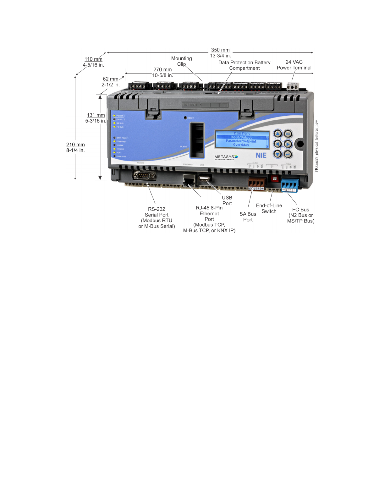
Figure 1: NIE29 Physical Features, Dimensions, and Required Mounting Space Around Engine
Mounting
Location Considerations
Follow these guidelines when mounting an NIE:
• Ensure that the mounting surface can support the NIE and any user-supplied panel or enclosure.
• Mount the NIE in a horizontal, upright orientation.
• Mount the NIE on an even surface in wall mount applications whenever possible. If you must mount the NIE on
an uneven surface, be careful not to crack the mounting clips or NIE housing when tightening the screws. Use
shims or washers to mount the NIE evenly on the mounting surface.
•
Mount the NIE in areas free of corrosive vapors, and observe the environmental limitations listed in the Technical
Specifications section.
•
Allow sufficient space to accommodate cable and wire connections (Figure 2).
• Do not mount the NIE where the ambient temperature may exceed 50°C (122°F).
• Do not mount the NIE on surfaces that are prone to vibration or in areas where electromagnetic or radio frequency
emissions can interfere with NIE communication.
• Do not obstruct the NIE housing ventilation holes.
• Do not mount a power transformer below the NIE.
On applications where the NIE is mounted inside a panel or enclosure, follow these additional guidelines:
• Do not install the NIE in an airtight enclosure.
• Do not install heat-generating devices in the enclosure with the NIE that may cause the ambient temperature to
exceed 50°C (122°F).
2NIE29 Installation Instructions
Page 3
Mounting the NIE
Wall Mount Applications
Use the holes in the three mounting clips for wall mount applications.
To mount the NIE on a wall (or other vertical surface):
1. Ensure that all three mounting clips are inserted into the back of the NIE housing and then pulled outward and
snapped firmly into the extended position (Figure 3).
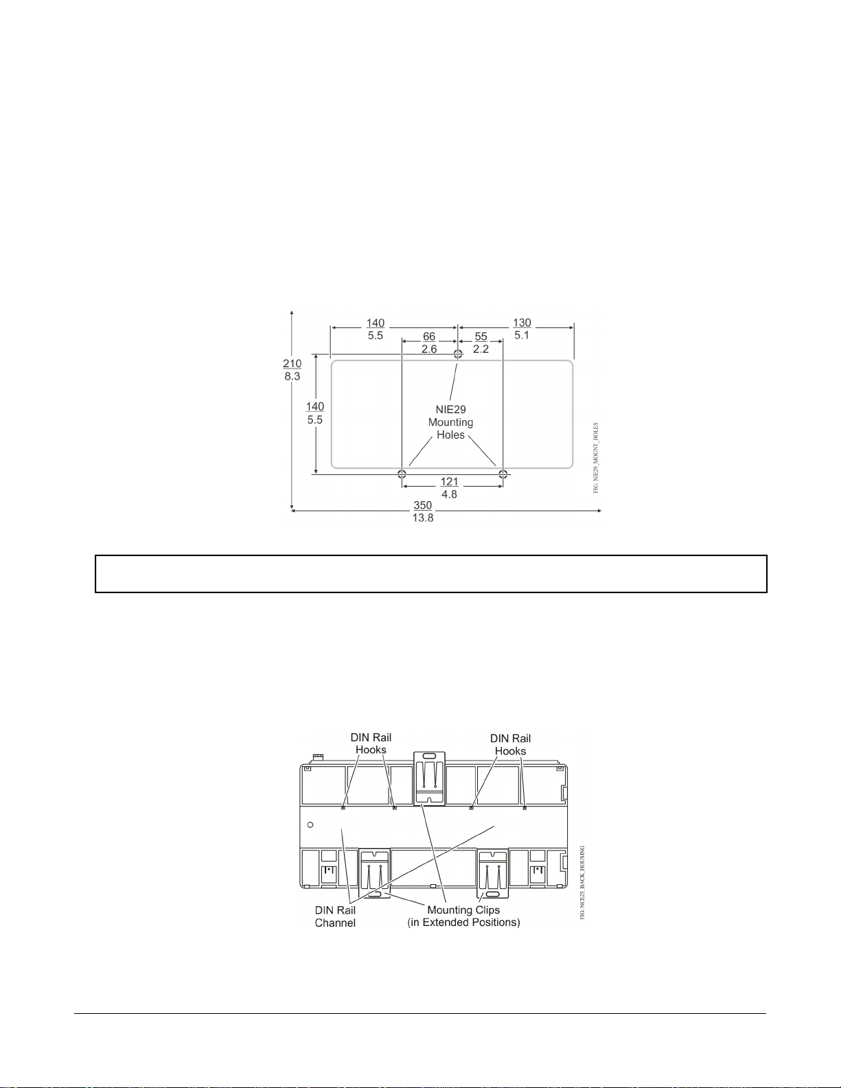
2. Mark the location of the three wall mount holes using the dimensions in Figure 2.
3. Drill holes in the wall at the locations marked in Step 2 and insert wall anchors (if necessary).
Figure 2: NIE Mounting Screw Hole Dimensions and Mounting Area Requirements (mm/in.)
4. Position the NIE and insert the screws through the holes in the mounting clips, and carefully tighten all the screws.
Important: Do not overtighten the mounting screws. Overtightening the screws may damage the mounting
clips or NIE housing.
DIN Rail Mount Applications
To mount the NIE on a DIN rail:
1. Securely mount a 20 cm (8 in.) or longer section of DIN rail horizontally and centered in the required space.
2. Ensure that the bottom two mounting clips are pulled outward and snapped firmly into the extended position
(Figure 3).
Figure 3: DIN Rail and Mounting Clip Features on the Back of an NIE
3. Hang the NIE by the DIN rail hooks (Figure 3) on the top track of the DIN rail, and position the NIE DIN rail
channel snugly against the tracks of the DIN rail.
4. Push the bottom mounting clips up to secure the NIE on the DIN rail tracks.
3NIE29 Installation Instructions
Page 4

To remove the NIE from the DIN rail, snap the bottom DIN clips to the outward extended position and carefully lift
the NIE off the DIN rail.
Enclosure Mount Applications
Mount the enclosure in accordance with the manufacturer’s instructions, and then mount the NIE in the enclosure
following the guidelines in the Location Considerations and Mounting the NIE sections.
Wiring
Power Supply, Network, and Communication Connections
See Figure 1 for the location of the NIE’s power supply terminal, bus terminals and ports, USB port, and Ethernet
port.
Note: Do not remove the red terminal block keys from the board mounted terminal blocks. Removing the keys can
result in a removable terminal plug being plugged into the wrong terminal block, which can cause the NIE to
malfunction.
24~ Supply Power Terminal Block
The 24~ supply power terminal block is a gray, keyed, removable 3-terminal block located on the top side of all NIE
models (Figure 1 and Figure 13).
In North America, the NIE requires a Class 2, 24 VAC, 25 VA minimum power supply. Outside North America, use
a 24 VAC safety extra-low voltage (SELV) transformer at the appropriate rating. A minimum input voltage of 20 VAC
is required for the NIE to operate properly.
Note: The maximum power consumption of an NIE29 is 25 VA, but that does not include power for internally sourced
binary output (BO) points. Applications that provide power to BO points and configurable output (CO) points
configured as BO points can require up to 125 VA of additional power over the 25 VA minimum required for
the NIE29.
SA Bus Terminal Block
The brown, keyed, removable, 4-terminal SA BUS terminal block (Figure 1) is provided on all NIE models. Connect
the 4-wire SA Bus cable to the SA BUS terminal block. See the SA Bus Rules section for more information.
SA Bus Modular Port
The 6-Pin modular Sensor/Actuator (SA) Bus port is available on all NIE models (Figure 1 and Figure 4). The SA
BUS port connects to:
• a Wireless Commissioning Converter (MS-BTCVT-1) to commission the NIE with the Controller Commissioning
Tool
• a DIS1710 Local Controller Display to provide a display screen on NIE29 models without an integral display
screen
• an NS Series Network Sensor to provide room temperature data to the NIE
4NIE29 Installation Instructions
Page 5
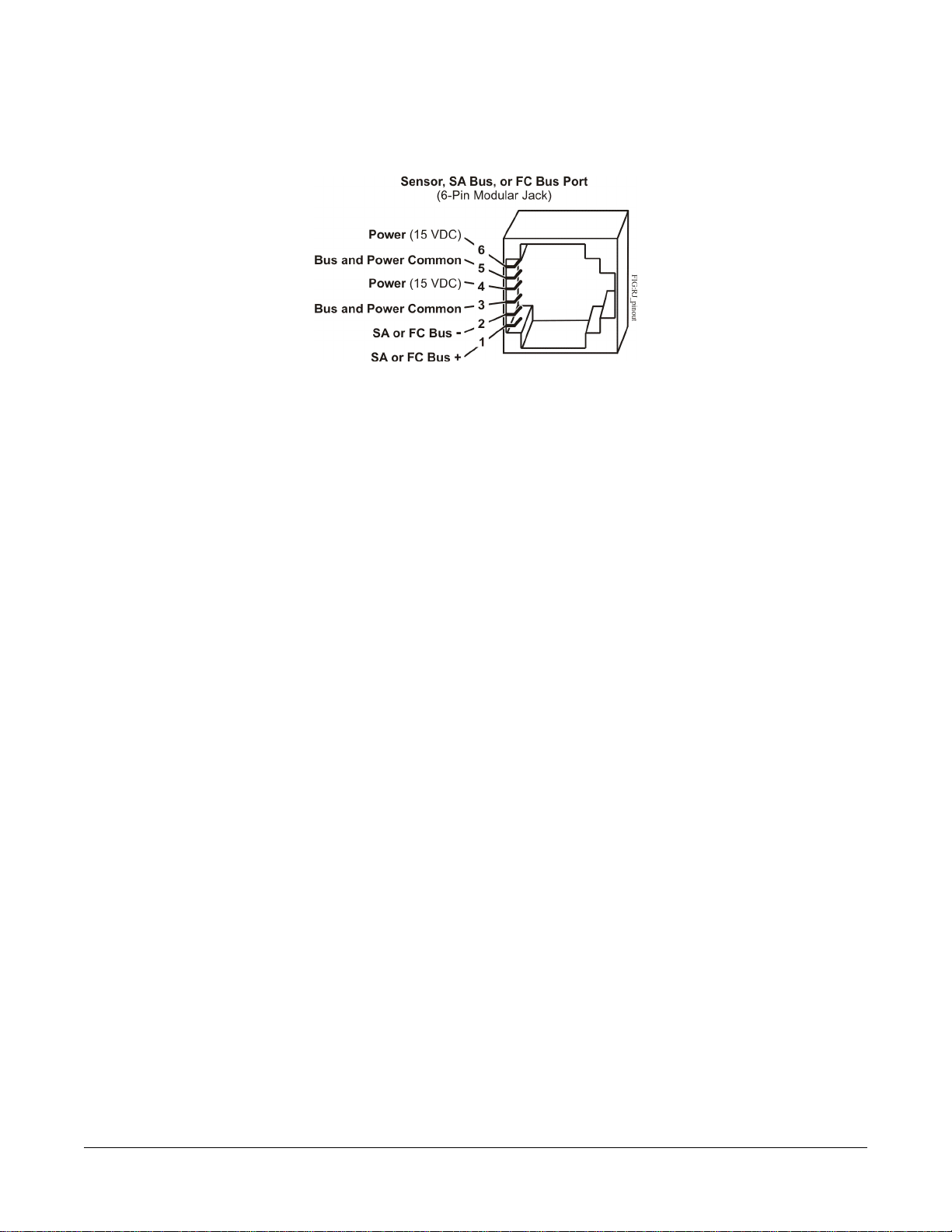
Figure 4: Pin Number Assignments for Sensor, SA Bus, and FC Bus Ports on NIE, FEC, IOM, and VMA16
FC Bus Terminal Block
The blue, keyed, removable 4-terminal block FC BUS terminal block (Figure 1) is designed for RS485 serial protocol
field buses and is available on NIE models that support N2 Bus, Master-Slave/Token-Passing (MS/TP) FC Bus
applications. Depending on the NIE29 model:
• connect the 3-wire N2 Bus to the FC BUS terminal block on NIE models that support N2 Bus applications. See
Figure 5 and the N2 Bus Rules section for more information.
• connect the 3-wire MS/TP FC Bus to the FC BUS terminal block on NIE models that support MS/TP FC Bus
applications. See Figure 5 and the MS/TP Bus Rules section for more information.
The SHLD terminal on the FC BUS terminal block can be used as a convenient terminal to connect cable shield
drains in daisy-chain bus applications that use shielded cable.
FC Bus Modular Port
The 6-pin modular Field Controller (FC) BUS port is available only on NIE models that support MS/TP or N2 Bus
applications (Figure 1 and Figure 4). Connect a Wireless Commissioning Converter (MS-BTCVT-1) to the modular
FC BUS port to commission the NIE with the Controller Configuration Tool (CCT).
LONWORKS® Network Terminal Block
The blue, keyed, removable, 3-position LON terminal block connects a LONWORKS network trunk to NIE29 models
that support a LONWORKS network trunk. The shield (SHD) on the LON terminal block is soft grounded to the NIE
chassis terminal, and you can use it as a convenient terminal to connect cable shield drains in daisy-chain bus
applications that use shielded cable.
RS232C Serial Port
The RS232C serial port provides direct connection to a Modbus RTU or M-Bus network using a standard 9-pin
female data terminal equipment (DTE) to 9-pin female DTE null modem cable. Integration of only one device is
permitted. If the RS232C serial port is not used to integrate a vendor protocol, you can connect to a computer serial
port to browse to the NIE or to connect to a VT100 or a computer with a VT100 emulator and perform diagnostic
procedures. Refer to the Metasys® System Extended Architecture Direct Connection and Dial-Up Connection
Application Note (LIT-1201639) for more information about direct connections to an NIE.
Standard USB Port
The USB port connects to an external flash drive that can store diagnostic information when the NIE is placed in
diagnostic mode. You can otherwise configure the USB serial port to use an optional, user-supplied external modem.
5NIE29 Installation Instructions
Page 6

Ethernet Port
The Ethernet port, labeled ETHERNET, is an 8-pin RJ-45 network port for connecting the NIE to Ethernet networks.
NIE29 engines can connect to Ethernet networks at 10 or 100 Mbps. Use this port for connecting a Modbus TCP,
M-Bus TCP, or KNX network.
Wiring Rules for Networks and Field Buses
All NIE29 Series models are designed to connect to Ethernet IP networks and support a single SA Bus.
Depending on the model, an NIE29 also supports either an MS/TP field bus trunk, an N2 Bus trunk, or a LONWORKS
network trunk. All models support two vendor integrations, such as two Modbus, two M-bus, or one of each. Or, if
a KNX integration is required, three KNX IP Gateways are supported for one NIE29. See Table 11 for a list of all
supported dual trunk applications. The rules, guidelines, and wiring considerations for each type of network or field
bus application are provided in the tables of this document.
IP Ethernet Network Rules
All NIE29 models are designed to connect to properly configured IP Ethernet networks, including Modbus TCP,
M-Bus TCP, or KNX. Refer to the N1 Ethernet/IP Network Technical Bulletin (LIT-6360175) for recommended parts
and part numbers. Observe the IP Ethernet network rules in Table 10.
Note: The Media Access Control (MAC) address is printed on a label on the NIE housing.
MS/TP Bus Rules
The MS/TP Bus connects Field Equipment Controllers (FECs), VMA1600s, Input/Output Modules (IOMs), TEC
Series thermostats, and third-party MS/TP controllers to NIE296-x models.
NIE296x models support an FC Bus trunk with up to 32 MS/TP devices. Observe the rules in Table 3 when designing
and installing the connected FC Bus.
SA Bus Rules
The Sensor/Actuator bus (SAB) connects the Metasys IOMs, NS Series Network Sensors, DIS1710 Local Controller
Display, specified variable frequency drives, and Wireless Commissioning Converter (MS-BTCVT-1) to an NIE.
Observe the rules in Table 4 when designing and installing the SA Bus for your application.
N2 Bus Rules
The N2 Bus connects N2 controllers to specified NIE29 models. NIE291x models support a single N2 Bus trunk with
up to 32 N2 devices.
Observe the rules in Table 1 when designing and installing the connected N2 Bus.
Modbus RTU Rules
The RS-232 port supports connection of one Modbus RTU (RS-232) device. With the addition of an RS-232/RS-485
converter and connection to the RS-232 port, up to 32 Modbus RTU (RS-485) devices are supported. Observe the
rules in Table 2 when designing and installing the connected Modbus RTU Bus.
LONWORKS Network Guidelines
The LON Bus connects up to 32 LONWORKS Network controllers to NIE292x models. Observe the rules in Table 7,
Table 8, and Table 9 when designing and installing the LONWORKS Network trunk.
For more information on LONWORKS networks, refer to the LONWORKS LN-Series Network Communication and Interface
Guide Technical Bulletin (LIT-12011253).
6NIE29 Installation Instructions
Page 7
Wiring the NIE
Important: Do not connect 24 VAC supply power to the NIE before finishing wiring and checking all wiring
connections. Short circuits or improperly connected wires may result in permanent damage to the
equipment.
Important: Use copper conductors only. Make all wiring in accordance with local, national, and regional regulations.
The NIE is a low-voltage device (<30 VAC) in North America and an extra low-voltage device in Europe.
Do not exceed the NIE electrical ratings.
Important: Do not remove the terminal block keys. The terminal block plugs and the terminal sockets are keyed
to fit together in the correct configuration only.
Important: Prevent any static electric discharge to the NIE. Static electric discharge can damage the NIE and void
any warranties.
Important: Ensure the network and field bus wiring meets the specifications, rules, and guidelines in the Power
Supply, Network, and Communication Connections section in this document.
Mount the NIE securely before wiring the NIE.
Follow these guidelines when wiring an NIE:
• Route the supply power wires and communication cables at least 50 mm (2 in.) away from the vent slots on the
sides of the NIE housing.
• Provide slack in the wires and cables. Keep cables routed neatly around the NIE to promote good ventilation,
LED visibility, and ease of service.
Wiring the NIE for N2, MS/TP, LONWORKS, or Modbus RTU Protocol
1. Connect the Ethernet cable to the RJ-45, 8-pin Ethernet port on the NIE shown in Figure 1.
2. If using an external modem, connect the modem to USB A using the proper cable.
3. Connect the Building Automation System (BAS) network cables to the appropriate ports.
For an N2 or MS/TP network, connect the 3-wire bus cable to one of the removable 4-terminal blue plugs
•
labeled FC Bus (Figure 5).
Note: If an N2 or MS/TP bus is connected to the NIE, you must set the NIE EOL switches to the proper
positions. See the Setting the End-of-Line Switch section. The Modbus RTU network does not require
termination.
• For LONWORKS compatible networks, connect the 2-wire cable from the LONWORKS network trunk to the
removable 3-terminal blue plug labeled LON (Figure 6).
Note: The LONWORKS network trunk is available on the NIE292x-0 model only.
7NIE29 Installation Instructions
Page 8
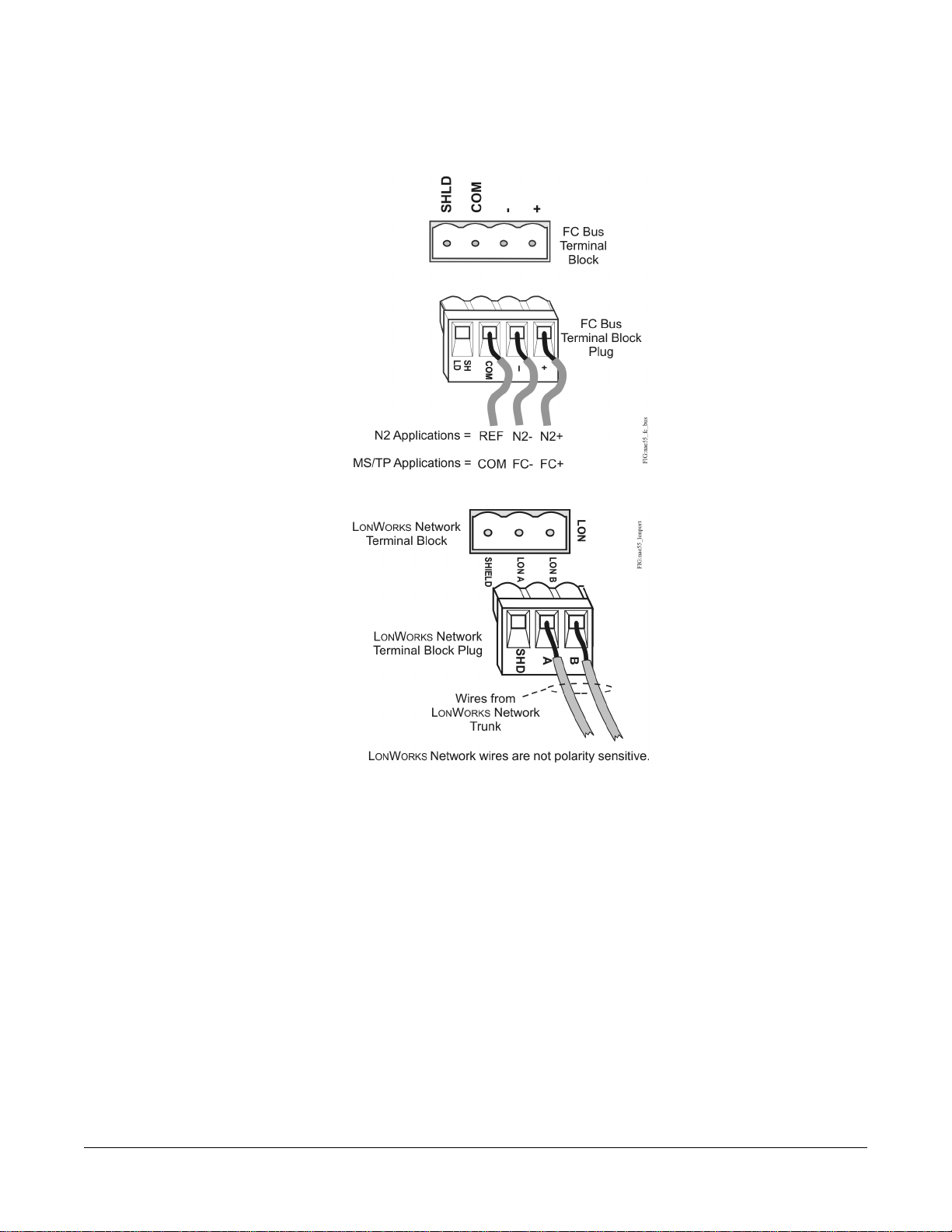
Figure 5: FC Bus Terminal Block and Wiring Connections
Figure 6: LONWORKS Network Terminal Block and Wiring Connections
4. For Modbus RTU (RS-485) protocol, use a cable to connect the RS-232/RS-485 converter to the RS232C serial
port on the NIE.
Note: The maximum cable length between devices connected though an RS-232 line depends on the baud
rate. In general, the length should not exceed 15 meters at 9600 baud.
5. Terminate the wires from the RS-485 terminal on the converter to the RS-485 port on the vendor device (Figure
7). The RS-485 bus is a two-wire network.
a. Connect the converter's + A terminal to the device's + (or A) terminal.
b. Connect the converter's - B terminal to the device's - (or B) terminal.
c. If the device has a Signal Ground or Reference terminal, connect this to the converter's CG2 terminal.
8NIE29 Installation Instructions
Page 9
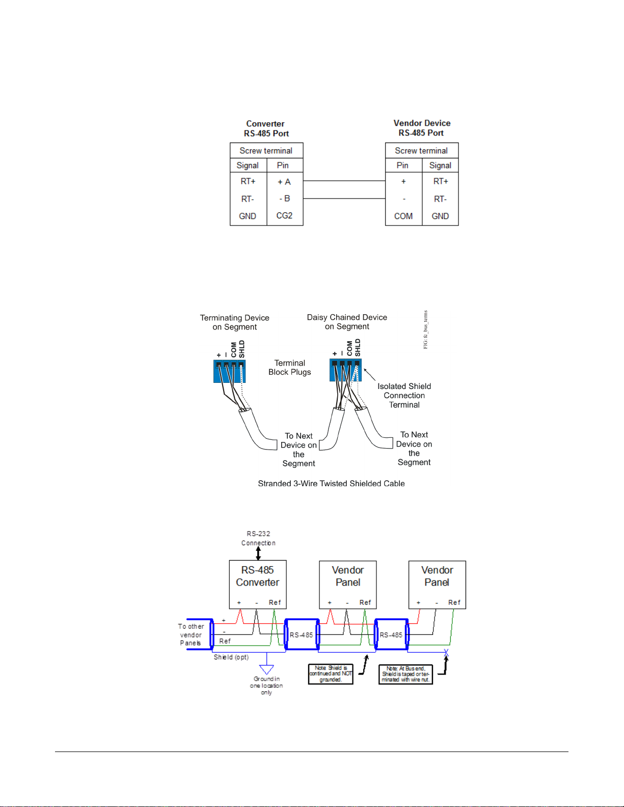
Figure 7: Connection Between Converter and Device
6. Set the NIE EOL switches to the proper position. See Setting the End-of-Line Switch.
7. To add additional vendor devices, terminate the wires from one device to the next as shown in Figure 8. No more
than two wires may be connected to each terminal to ensure the daisy chain configuration. See Wiring Rules for
Networks and Field Buses for the Modbus protocol.
Figure 8: Daisy Chained Devices
The completed wiring should look similar to Figure 9.
Figure 9: Modbus RTU Wiring Detail Overview
8. Terminate the 24 VAC supply power wires from the transformer to the removable power terminal block plug on
the NIE (Figure 10).
9NIE29 Installation Instructions
Page 10
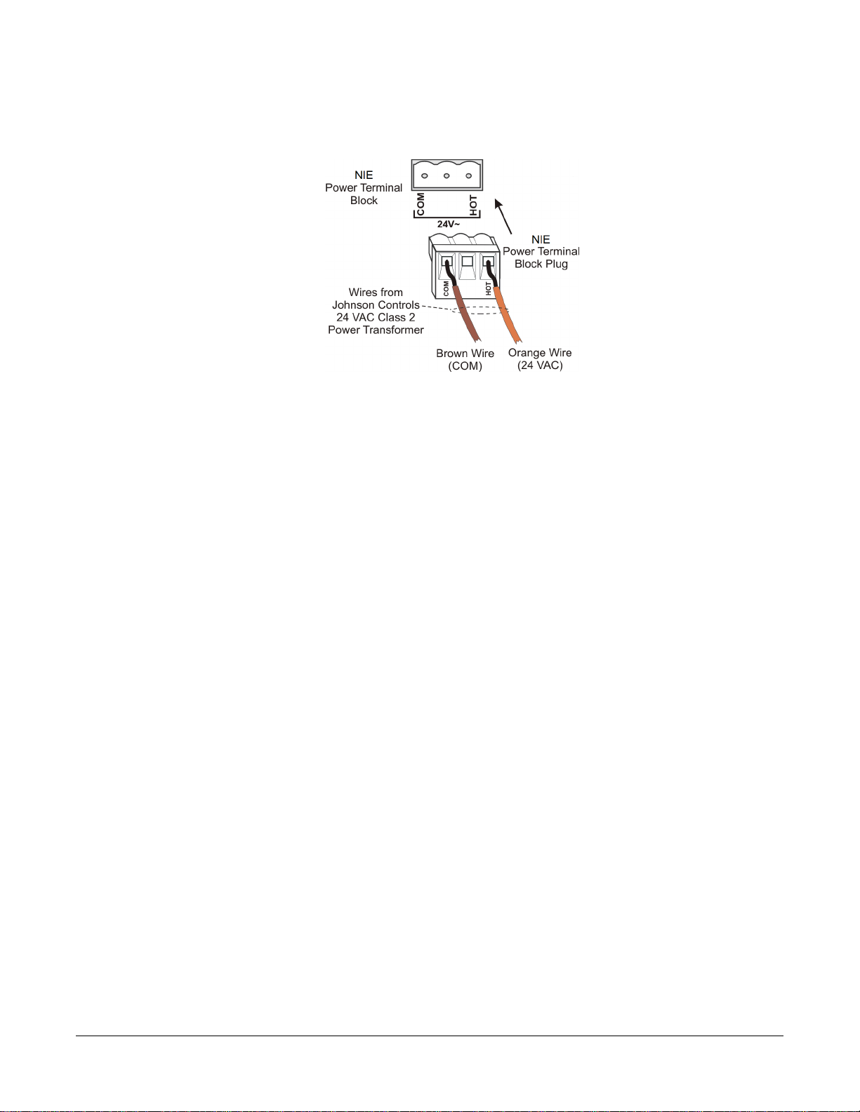
Figure 10: 24 VAC Supply Power Wiring
Note: Power supply wire colors may be different on transformers not manufactured by Johnson Controls. Follow
the transformer manufacturer’s instructions and the project installation drawings.
9. Terminate the 24 VAC supply power wires from the transformer to the converter. No additional external power
adapter is required. Terminate the hot and common wires as desired. The NIE does not require an earth ground
connection.
Note: The 24 VAC power should be terminated to all network devices so transformer phasing is uniform across
the devices. Powering network devices with uniform 24 VAC supply power phasing reduces noise,
interference, and ground loop problems.
Wiring the NIE for M-Bus Protocol
1. Connect the Ethernet cable to the RJ-45, 8-pin Ethernet port shown in Figure 1.
2. Connect from the RS232C serial port on the NIE to the RS-232 connecter of the level converter. Wire to terminals
GND, RxD, and TxD as shown in Figure 11.
3. Terminate the M- and M+ wires on the level converter (Figure 11) to the meters using a free (star, tree, or line)
topology. Specific cabling can vary depending on the topology and site. See Wiring Rules for Networks and Field
Buses.
Note: If the number of M-Bus unit loads or distances exceeds the specifications of a level converter, you can
connect an M-Bus repeater to the converter to increase the number of unit loads and distances. The
converter shown in Figure 11 is capable of handling up to 6 units loads, while other models can handle
up to 100. See NIE29 Model Ordering Information Table for a list of M-Bus devices.
4. Terminate the 24 VAC supply power wires from the transformer to the removable power terminal block plug on
the NIE (Figure 10).
Note: Power supply wire colors may be different on transformers not manufactured by Johnson Controls. Follow
the transformer manufacturer’s instructions and the project installation drawings.
5. Terminate the 24 VAC supply power wires from the transformer to the -/~ and +/~ terminals as shown in Figure
11.
10NIE29 Installation Instructions
Page 11

Figure 11: M-Bus Level Converter
Wiring the NIE for KNX Protocol
1. Connect an Ethernet cable to the RJ-45, 8-pin Ethernet port shown in Figure 1.
2. Connect another Ethernet cable to the port on the front of the KNX gateway (Figure 12).
Note: Depending on the size of your network, you can use either a KNX interface or router as a gateway. The
Interface connects the NIE to a single KNX line, while the router acts as both an interface and a line
coupler over Ethernet to connect the NIE to the network, not to a single device.
11NIE29 Installation Instructions
Page 12

Figure 12: KNX/IP Interface Router
3. For a single KNX line, terminate the wires from the red and black terminals on the gateway to the devices. For
multiple KNX lines, terminate the wires from the red and black terminals on each gateway to the devices on the
same KNX line.
Note: Specific cabling can vary depending on the topology and site. See Wiring Rules for Networks and Field
Buses.
4. Terminate each KNX gateway to its own dedicated power supply on the KNX line.
Wiring Input and Output Terminals
NIE29 Series models support up to 33 hard-wired I/O points including:
• 7 BO points
• 4 CO points
• 4 analog output (AO) points
• 8 binary input (BI) points
• 10 Universal Input (UI) points
See Figure 13, Figure 14, and Terminal Wiring and Cable Length Guidelines Tables for more information.
The I/O points are designed for multiple types of input or output, and most of the points are configured in the CCT
software.
Terminal Functions, Ratings, Requirements, and Wiring Guidelines
Input and Output Wiring Guidelines
Table 12 provides information and guidelines about the functions, ratings, and requirements for the NIE input and
output terminals and references to guidelines for determining proper wire sizes and cable lengths.
12NIE29 Installation Instructions
Page 13

In addition to the wiring guidelines in Table 12, observe these guidelines when wiring NIE inputs and outputs:
• Run all low-voltage wiring and cables separate from high-voltage wiring.
• All input and output cables, regardless of wire size or number of wires, should consist of stranded, insulated,
and twisted copper wires.
• Shielded cable is not required for input or output cables.
• Shielded cable is recommended for input and output cables that are exposed to high electromagnetic or radio
frequency noise.
Inputs/outputs with cable runs under 30 m (100 ft) typically do not require an offset in the software setup. Cable runs
over 30 m (100 ft) may require an offset in the input/output software setup.
Table 13 defines cable length guidelines for the various wire sizes that may be used for input and output wiring.
Maximum Cable Length versus Load Current
Use Figure 15 to estimate the maximum cable length relative to the wire size and the load current (in mA) when
wiring inputs and outputs.
FC and SA Bus and Supply Power Wiring Guidelines
Table 14 provides information about the functions, ratings, and requirements for the NIE communication bus and
supply power terminals, and guidelines for wire sizes, cable types, and cable lengths when wiring the NCE
communication buses and supply power.
In addition to the guidelines in Table 14, observe these guidelines when wiring the SA/FC Buses and supply power:
• Run all low-voltage wiring and cables separate from high-voltage wiring.
• All FC and SA Bus cables, regardless of wire size, should be twisted, insulated, stranded copper wire.
• Shielded cable is strongly recommended for all FC and SA Bus cables.
•
Refer to the MS/TP Communications Bus Technical Bulletin (LIT-12011034) for detailed information regarding
wire size and cable length requirements for the FC and SA buses.
13NIE29 Installation Instructions
Page 14

Input Output Blocks Graphic
Figure 13: NIE29 Series Output Terminal Blocks, Binary Output Jumpers, and Supply Power Terminal Block
Figure 14: Universal Input and Binary Input Terminal Blocks
Wiring Rules and Guidelines for Network Integrations
Table 1: N2 Bus Network Rules
Rules/Maximums AllowedCategory
General
Supported
Cable Length and Type
Cable
One N2 trunk network supported (on NIE291x models only).
Only daisy-chained devices (with maximum stub length of 3 m [10 ft] to any device)
Up to 32 N2 devices supported on the trunk.Number of Devices
1,500 m (4,921 ft) twisted pair cable
2,000 m (6,561 ft) between two fiber modems
Solid or stranded 1.0 mm (18 AWG) 3-wire is recommended. Solid or stranded 0.5 mm (24 AWG)
larger 3-wire or 4-wire (two twisted-pairs) is acceptable.
Note: The + and - bus leads should be a twisted pair. On applications using 4-wire (two
twisted-pairs) cable, isolate and insulate unused conductor.
N2 devices are self terminating and have no end-of-line (EOL) setting.Bus Termination
14NIE29 Installation Instructions
Page 15

Table 2: Modbus RTU Rules Table
Rules/Maximums AllowedCategory
General
Number of Devices
Cable Length
Cable
Termination
One direct Modbus RTU (RS-232) connection to the RS232C port is supported.
Connection of an RS-232/RS-485 converter to the RS232C port supports up to 32 Modbus
(RS-485) devices.
FC port does not support Modbus integration.
RS232C port supports one Modbus RTU (RS-232) device.
RS232C port with RS-232/RS-485 converter supports up to 32 Modbus (RS-485) devices.
RS-232 cable length can be up to 15 m (49.2 ft).
RS-485 cable length can be up to 1,520 m (4,987 ft).
RS-232 stranded cable, 3-9 conductors, serial data grade, 20–24 AWG
RS-485 stranded cable, 0.6 mm (22 AWG) 3-wire twisted, shielded cable is recommended.
Stranded 0.6 (22 AWG) 4-wire (two twisted pairs) shielded is acceptable.
RS-232: requires no termination.
RS-485: End-of-line (EOL) termination must be set to On (or an EOL terminator installed) on the
two devices located at either end of each bus segment on an RS-485 bus. The EOL switches
must be set to Off (or EOL termination disabled) for all other devices on the bus segment on an
RS-485 bus.
Table 3: MSTP FC Bus Rules Table
Rules/Maximums AllowedCategory
General
Cable Length for FC Bus
Cable
EOL Termination on the FC
Bus
One FC Bus with up to 32 MS/TP devices (on NIE296x models only)
Note: An FC port on an NIE296x can connect to only one bus segment on an FC Bus.
Only a daisy-chain topology is allowed (no T or Star topology configurations).
Supports up to 32 MS/TP controllers on a single FC Bus segment.Number of Devices
FC Bus can be up to 1,520 m (4,987 ft) using 0.6 mm (22 AWG) 3-wire twisted, shielded cable1.
When using fiber-optic connections: 2,010 m (6,594 ft) between two fiber-optic modems
Stranded 0.6 mm (22 AWG) 3-wire twisted, shielded cable is recommended.
Stranded 0.6 mm (22 AWG) 4-wire (two twisted-pairs) shielded cable is acceptable.
Note: The + and - bus leads should be a twisted pair. On applications using 4-wire (two
The EOL switch must be set to On (or an EOL terminator installed) on the two devices located
at either end of each bus segment on an FC Bus. The EOL switches must be set to Off (or EOL
termination disabled) for all other devices on the bus segment on an FC Bus. See Setting the
End-of-Line Switch for information on setting the NIE EOL switch.
twisted-pairs) cable, isolate and insulate unused conductor. Refer to the MS/TP
Communications Bus Technical Bulletin (LIT-12011034) for more information.
1 If third-party devices are connected to the bus, the cable lengths should be reduced (if necessary) to match the third-party
vendor recommendations.
15NIE29 Installation Instructions
Page 16

Table 4: SA Bus Rules
Number of Devices
Supported on the Bus
SAB Cable Length
Recommended Bus Cable
1
Type
EOL Termination on the SAB
Rules/LimitsCategory
Each bus supervisor supports one SAB.General
An SAB supports up to 10 devices.
Note: The SAB supervisor provides power for the NS network sensors on the bus. Due to
power limitations, only 4 of the 10 devices on an SAB can be NS sensors.
Note: The SAB on NIE29 models that have an integral Local Controller Display do not support
an optional DIS1710 Local Controller Display.
SABs do not support repeaters.
365 m (1,198 ft) maximum bus length
152 m (500 ft) maximum between an NS network sensor and the bus supervisor FEC or VAV
Modular Assembly (VMA) supplying power to the sensor) using bus cable connected to the SAB
screw terminal blocks
30 m (98 ft) maximum length for network sensors using bus cables connected to the 6-pin
modular jack (6-Pin SAB port)
366 m (1,198 ft) maximum bus length
1.5 m (5 ft) maximum between NIE and DIS1710 Local Controller Display
Screw Terminal Connections: 0.6 mm (22 AWG) Stranded 4-wire, 2-wire twisted pair, Shielded
Cable for screw terminals
Modular Jack Connections: 6-Pin Modular Connectors with 24 or 26 AWG 6-wire, 3-wire twisted
pair
Each SAB supervisor has integral (fixed ON) EOL termination, which typically provides sufficient
EOL termination on an SAB. Long SAB runs or persistent communication problems on an SAB
may require EOL termination at the last device on the SAB (in addition to the integral EOL
termination at the SAB supervisor). All NIE29 models are SAB supervisors.
1 If third-party devices are connected to the bus, the cable lengths should be reduced (if necessary) to match the third-party
vendor recommendations. Also, use only one type of connection, either Screw Terminal or Modular Jack, but not a combination
of both.
Table 5: Rules for M-Bus Protocol
Rules/Maximums AllowedCategory
General
One direct M-Bus serial (RS-232) connection to the RS232C port is supported.
Connection requires an RS232-to-M-Bus Level Converter on the RS232C port.
FC port does not support M-Bus integration.
No restrictions in topology, but bus topology is strongly recommended
Depends on level converter (logical maximum is 250 devices).Number of Devices
16NIE29 Installation Instructions
Page 17

Table 5: Rules for M-Bus Protocol
Rules/Maximums AllowedCategory
Line Length and Type
Length depends on cable resistance, capacitance, number of devices, position of devices, and
configured communication speed. Example scenarios to help with calculation:
Baud
Rate
Twisted pair cable (shielding optional)Cable
No terminationTermination
Maximum Number of Unit
1, 2
Loads
Maximum Distance
Between Converter and
Devices
3,000 m (9,842 ft)642400
1,000 m (3,281 ft)64
350 m (1,148 ft)250
350 m (1,148 ft)649,600
350 m (1,148 ft)250
350 m (1,148 ft)6438,400
Maximum Distance for
Entire Bus
5,000 m (16,404 ft)
(2 x 1.0 mm [18 AWG],
shield recommended,
resistance < 90 Ohms)
4,000 m (13,123 ft)
(2 x 1.0 mm [18 AWG],
shielded, resistance < 90
Ohms)
4,000 m (13,123 ft)
(2 x 0.8 mm [20 AWG],
shielded, resistance < 30
Ohms)
4,000 m (13,123 ft)
(2 x 0.8 mm [20 AWG],
shielded, resistance < 30
Ohms)
1,000 m (3,281 ft)
(2 x 0.8 mm [20 AWG],
shielded, resistance < 30
Ohms)
1,000 m (3,281 ft)
(2 x 0.8 mm [20 AWG],
shielded, resistance < 30
Ohms)
1 Unit load is a defined standby current. A device is permitted a current drain of one unit load by default but may consume
more if it is shown at the device (by an integer) and in documentation.
2 Use M-Bus Repeaters to increase the length and the number of unit loads permissible.
Table 6: Rules for KNX Protocol
Rules/Maximums AllowedCategory
No restrictions in topologyGeneral
Depends on chosen topology and cable typeNumber of Devices
Line Length and Type
Cable
Twisted pair cable recommended; length depends on cable resistance, capacitance, number
devices, position of devices, and communication speed.
Copper, solid and stranded wires with outer sheath, one- or two-twisted pair; 0.8 to 1.0 mm (20
to 18 AWG)
Screen is required and must cover the entire diameter.
Drain wire: Diameter minimum 0.4 mm (26 AWG)
17NIE29 Installation Instructions
Page 18

Table 6: Rules for KNX Protocol
Rules/Maximums AllowedCategory
No terminationTermination
At least ISO 9002Manufacturer's Quality
Management System
Table 7: Guidelines for LONWORKS Network Bus Topology
Cable Type
1 For the bus topology, the maximum length stub cable is 3 m (10 ft), and the stub lengths must be calculated into the overall
segment length.
Maximum Segment Length with FTT10
Devices Only
1
Maximum Segment Length with
FTT10 and/or LPT10 Devices
2,200 m (7,218 ft)2,700 m (8,858 ft)Belden® 85102 Cable
2,200 m (7,218 ft)2,700 m (8,858 ft)Belden 8471 Cable
1,150 m (3,773 ft)1,400 m (4,593 ft)Level IV 0.6 mm (22 AWG)
750 m (2,460 ft)900 m (2,953 ft)JY (St.) Y 2 x 2 x 0.8
1
Table 8: Guidelines for LONWORKS Network Free Topology
Maximum Node-to-Node DistanceCable Type
Maximum Segment Length with
FTT10 and/or LPT10 Devices
500 m (1,640 ft)500 m (1,640 ft)Belden 85102 Cable
500 m (1,640 ft)500 m (1,640 ft)Belden 8471 Cable
500 m (1,640 ft)400 m (1,312 ft)Level IV 0.6 mm (22 AWG)
500 m (1,640 ft)320 m (1,050 ft)JY (St.) Y 2 x 2 x 0.8
Table 9: Maximum Number of Devices per LONWORKS Network Segment
Maximum AllowedDevice Type
32 LONWORKS devices supported (on NIE292x Type models only).FTT-10 Nodes Only
1
Nodes
Terminators
1 Each LPT10 channel segment (between repeaters) requires its own power supply. Other factors, such as power consumption
of individual LPT10 devices, may limit a segment to fewer devices. The NCE does not have an internal network terminator.
([FTT10 x 2] + LPT10) < 32Mixed FTT-10 and LPT-10
2 bus type EOL terminators required (NU-EOL202-0)Bus Topology
1 free topology terminator required (NU-EOL203-0)Free Topology
Maximum of 1 per segmentPhysical Layer Repeaters
Table 10: NIE Ethernet Network Rules
Category
Number of Devices
Rules/Maximums Allowed
Point-to-point star topology with network hubs and switchesGeneral
Maximum of 100 supervisory devices may be connected to one site in the Metasys system.
2,000 m (6,600 ft) for plastic or glass fiber optic with external adapterLine Length and Type
100 m (330 ft) CAT5 cable
For 10/100 BaseT, no line terminators allowedTerminations
1
18NIE29 Installation Instructions
Page 19

Table 11: NIE29 Dual Trunk Options
Supported Dual Trunk ApplicationTrunk Type
Modbus
M-Bus
Modbus and M-Bus
1
Refer to the N1 Ethernet/IP Network Technical Bulletin (LIT-6360175) for recommended parts and part numbers.
1 RS232
1 TCP
2 TCP
1 RS232
1 TCP
2 TCP
1 RS232 Modbus
1 TCP M-Bus
1 RS232 M-Bus
1 TCP ModBus
1 TCP Modbus
1 TCP M-Bus
19NIE29 Installation Instructions
Page 20

Terminal Wiring and Cable Length Guidelines Tables
Table 12: Terminal Wiring
Determine Wire Size and
Maximum Cable Length
Same as (Universal) INn.
Note: Use 3-wire cable for
See Guideline A in Table 13.
See Guideline B in Table 13.
See Guideline A in Table 13.
See Guideline A in Table 13.
Same as (Universal) INn.Universal Input Common for all Universal
See Guideline A in Table 13.
Label
(Inputs)
BINARY
(Inputs)
Terminal LabelsTerminal Block
+15 VUNIVERSAL
INn
ICOMn
INn
ICOMn
Function, Ratings, and
Requirements
15 VDC Power Source for active (3-wire)
input devices connected to the Universal
INn terminals.
Provides 100 mA total current.
Analog Input - Voltage Mode (0–10 VDC)
10 VDC maximum input voltage Internal
75k ohm Pulldown
Analog Input - Current Mode (4–20 mA)
Internal 100 ohm load Impedance
Analog Input - Resistive Mode (0–600k
ohm)
Internal 12 V, 15k ohm pull up
Qualified Sensors: 0–2k potentiometer,
Resistence Temperature Detector (RTD),
1k Nickel sensor, 1k Platinum, and A99B
Silicon temperature sensor
Negative Temperature Coefficient (NTC)
Sensor (10k Type L, 10k JCI Type II,
2.252k Type II)
Binary Input - Dry Contact Maintained
Mode1 second minimum pulse width
Internal 12 V, 15k ohm pull up
IN terminals
Note: All Universal ICOMn terminals
share a common, which is isolated
from all other commons.
Binary Input - Dry Contact Maintained
Mode
0.01 second min. pulse width
Internal 18 V, 3k ohm pull up
Binary Input - Pulse Counter Mode
0.01 second min. pulse width
(50 Hz at 50% duty cycle)
Internal 18 V, 3k ohm pull up
Binary Input Common for all Binary Input
(IN) terminals
Note: All Binary ICOMn terminals share
a common, which is isolated from
all other commons, except the CO
common (OCOMn) when the CO
is defined as an AO.
1
devices that source
power from the +15 V
terminal.
20NIE29 Installation Instructions
Page 21

Table 12: Terminal Wiring
Terminal LabelsTerminal Block
Label
ANALOG
(Outputs)
BINARY
(Outputs)
Power Selection
Jumper positioned to
External (EXT).
OUTn
OCOMn
OUTn
OCOMn
Function, Ratings, and
Requirements
Analog Output - Voltage Mode (0–10
VDC)
10 VDC maximum output voltage
10 mA maximum output current
Requires an external load of 1,000 ohms
or more.
Note: The AO operates in Voltage Mode
when connected to devices with
impedances greater than 1,000
ohms. Devices that drop below
1,000 ohms may not operate as
intended for Voltage Mode
applications.
Analog Output - Current Mode (4–20
mA)
Requires an external load between 0–300
ohms.
Note: The AO operates in Current Mode
when connected to devices with
impedances less than 300 ohms.
Devices that exceed 300 ohms
may not operate as intended for
Current Mode applications.
Analog OUT terminals.
Note: All Analog OCOMn terminals
share a common, which is isolated
from all other commons.
Binary Output - 24 VAC Triac (External
Power)
Connects OUTn to OCOMn when
activated.
External Power Source:
30 VAC maximum output voltage
0.5 A maximum output current
1.3 A at 25% duty cycle
Maximum 6 cycles/hour with M9220-BGx-3
40 mA minimum load current
Binary Output Common (for OUTn
terminal)
Note: Each Binary Output common
terminal (OCOMn) is isolated from
all other commons, including other
Binary Output commons.
Determine Wire Size and
Maximum Cable Length
See Guideline A in Table 13.
See Guideline B in Table 13.
Same as (Analog) OUTn.Analog Output Signal Common for all
See Guideline C in Table 13.
1
21NIE29 Installation Instructions
Page 22

Table 12: Terminal Wiring
Terminal LabelsTerminal Block
Label
BINARY
(Outputs)
Power Selection
Jumper positioned to
Internal (INT).
CONFIGURABLE
(Outputs)
OUTn
OCOMn
OUTn
OCOMn
Function, Ratings, and
Requirements
Binary Output - 24 VAC Triac (Internal
Power)Sources internal 24 VAC power
(24~ HOT)
Binary Output - 24 VAC Triac (Internal
Power) Connects OCOMn to 24~ COM
when activated.
Internal Power Source:
30 VAC maximum voltage to load
0.5 A maximum output current
1.3 A at 25% duty cycle
Maximum 6 cycles/hour with M9220-BGx-3
40 mA minimum load current
Analog Output - Voltage Mode (0–10
VDC)
10 VDC maximum output voltage
10 mA maximum output current
Requires an external load of 1000 ohm or
more
Binary Output 24 VAC Triac
Connects OUT to OCOM when activated.
External Power Source:
30 VAC maximum voltage to load
0.5 A maximum output current
1.3 A at 25% duty cycle
Maximum 6 cycles/hour with M9220-BGx-3
40 mA minimum load current
Configurable Outputs defined as Analog
Outputs share a common, which is isolated
from all other commons except the Binary
Input common
Binary Output Signal Common: All
Configurable Outputs defined as Binary
Outputs are isolated from all other
commons, including other Configurable
Output commons.
Determine Wire Size and
Maximum Cable Length
See Guideline C in Table 13.
See Guideline A in Table 13.
See Guideline C in Table 13.
Same as (Configurable) OUTn.Analog Output Signal Common: All
1
1 See to determine wire size and cable lengths for cables other than the recommended cables.
22NIE29 Installation Instructions
Page 23

Table 13: Cable Length Guidelines for Recommended Wire Sizes
Wire Size/Gauge and TypeGuideline
AssumptionsMaximum Cable Length
and Type
100 mV maximum voltage drop457 m (1,500 ft) twisted wire1.0 mm (18 AWG) stranded copperA
297 m (975 ft) twisted wire0.8 mm (20 AWG) stranded copper
183 m (600 ft) twisted wire0.6 mm (22 AWG) stranded copper
107 m (350 ft) twisted wire0.5 mm (24 AWG) stranded copper
229 m (750 ft) twisted wire1.0 mm (18 AWG) stranded copperB
137 m (450 ft) twisted wire0.8 mm (20 AWG) stranded copper
91 m (300 ft) twisted wire0.6 mm (22 AWG) stranded copper
61 m (200 ft) twisted wire0.5 mm (24 AWG) stranded copper
C
See Figure 15 to select wire size/gauge. Use
stranded copper wire.
See Figure 15 to determine
cable length. Use twisted wire
cable.
Depending on the cable length
and the connected input or
output device, you may have to
define an offset in the setup
software for the input or output
point.
100 mV maximum voltage drop
Depending on the cable length
and the connected input or
output device, you may have to
define an offset in the setup
software for the input or output
point.
N/A
Maximum Cable Length versus Load Current Graphic
Figure 15: Maximum Wire Length by Current and Wire Size
23NIE29 Installation Instructions
Page 24

Communications Bus and Supply Terminal Blocks, Functions, Ratings, Requirements, and Cables Table
Table 14: Communications Bus and Supply Terminal Blocks, Functions, Ratings, Requirements, and Cables
Recommended Cable
1
Type
0.6 mm (22 AWG) stranded,
3-wire twisted, shielded cable
recommended
Wireless Commissioning
Converter retractable cable or
24 AWG 3-pair CAT 3 Cable
<30.5 m (100 ft)
0.6 mm (22 AWG) stranded,
3-wire twisted, shielded cable
recommended
Note: The + and - wires are
one twisted pair and
the COM and SA PWR
are the second twisted
pair of wires.
24 AWG 3-pair CAT 3 Cable
<30.5 m (100 ft)
0.8 mm to 1.5 mm (20 to 16
AWG) 2-wire
Block/Port
Label
FC BUS
FC Bus
(port)
SA BUS
SA BUS
(Port)
2
2
2
_
_
SA PWR
HOT24~
COM
Function, Electrical Ratings/RequirementsTerminal LabelsTerminal
FC Bus Communications+
Signal Reference (Common) for bus communicationsCOM
Isolated terminal (optional shield drain connection)SHLD
6-Position Modular Connector provides:
• FC Bus Communications
• FC Bus Signal References and 15 VDC Common
• 15 VDC Power for Wireless Commissioning
• Converter or ZFR1811 Wireless Router
SA Bus Communications+
SA Bus Signal Reference and 15 VDC CommonCOM
15 VDC Supply Power for Devices on the SA Bus
(Maximum total current draw for SA Bus is 240 mA.)
6-Position Modular Connector provides:
• SA Bus Communications
• SA Bus Signal References and 15 VDC Common
• 15 VDC Power for devices on the SA Bus and
• Wireless Commissioning Converter
24 VAC Power Supply - Hot
Supplies 20-30 VAC (Normal 24 VAC)
24 VAC Power Supply Common (Isolated from all other
Common terminals on controller)
1
See Table 13 to determine wire size and cable lengths for cables other than the recommended cables.
2 The SA Bus and FC Bus wiring recommendations in this table are for MS/TP bus communications at 38.4k baud. For more
information, refer to the MS/TP Communications Bus Technical Bulletin (LIT-12011034)
Setup and Adjustments
Data Protection Battery
The NIE is shipped with the data protection battery installed and connected. Do not disconnect the battery for any
reason other than to replace a defective battery.
The 24 VAC supply power to the NIE charges the data protection battery. At initial startup, the battery may require
a charging period of at least 4 hours before it supports data protection if power fails. Maximum protection (up to 3
consecutive power failures without recharging time) requires a 15-hour charging period.
The data protection battery slowly loses charge when 24 VAC power is removed from the NIE. If the battery completely
loses charge, the NIE real-time clock stops.
24NIE29 Installation Instructions
Page 25

Whenever an NIE is disconnected from 24 VAC power for over 30 days, ensure that the real-time clock is set properly
and that the NIE is powered long enough to recharge the data protection battery.
Powering On the NCE
After applying 24 VAC power, the NIE requires approximately 5 minutes to start up and become operational. See
the LED Test Sequence at Startup.
Startup is complete and the NIE is operational when the green RUN LED is On steady and the red FAULT LED is
Off (LED Status Indicators).
Important: Wait for the NIE to complete the start-up sequence and the RUN LED to go On steady before initiating
any other action on the NIE.
Disconnecting Power from the NCE
When 24 VAC supply power to an NIE is disconnected or lost, the NIE is nonoperational, but the POWER LED
(Figure 18) remains On and the data protection battery continues to power the NIE for several (approximately 1 to
8) minutes while volatile data is backed up in nonvolatile memory. The RUN LED goes Off when data backup and
shutdown is complete.
Important: The data protection battery must be installed and charged before disconnecting the 24 VAC supply
power.
Setting the End-of-Line Switch
RS485 serial protocol bus segments require proper EOL termination to reduce interference from signal bounce back
on the bus segment.
FC Bus MS/TP and Mobus RTU applications require a terminated device at each end of each FC Bus segment. See
the MS/TP Bus Rules section for more information on EOL requirements on an FC Bus.
N2 Bus applications are self terminating and have no EOL setting. See the N2 Bus Rules section for more information
on EOL requirements on an N2 Bus.
The NIE29 models that support MS/TP FC Bus applications or N2 Bus applications have an EOL switch, which must
be set according to the position of the NIE on the FC Bus or N2 Bus segment. The NIE29 is shipped with the EOL
switch in the factory default, ON (up) position (Figure 16).
Figure 16: FC Bus EOL Switch in the Factory Default ON (Up) Position
See to determine the appropriate EOL switch setting for the NIE in your field bus application.
25NIE29 Installation Instructions
Page 26

Figure 17: EOL Switch Setting Relative to NIE Position on the N2 Bus or FC Bus Segment
Setting the Network and Device Addresses
You must assign a new IP network address to the NIE29, so it can communicate on the IP Ethernet network. The
NIE29 MAC address is fixed and is printed on a label on the housing.
The NIE29 is always the SA Bus supervisor and, therefore, always has a fixed device address of 0 on the SA Bus.
The supervisory controller on NIE29 models that support an (MS/TP) FC Bus is always an FC Bus supervisor and
has a fixed device address of 0 on the FC Bus. The field controllers in all the NIE29 models have fixed device
addresses of 4 on the NIE FC Bus.
Refer to the MS/TP Communications Bus Technical Bulletin (LIT-12011034) for more information on device addresses
on (MS/TP) FC Buses and SA Buses.
NIE29 models that support an N2 Bus are always bus supervisors on the N2 Bus, and they do not require a user
assigned device address to communicate on the N2 Bus.
NIE29 models that support a LONWORKS network trunk are assigned a unique, factory-assigned Neuron® ID. A
network management tool, such as LN Builder, uses this Neuron ID to set the domain, subnet, and node address
of the NIE29 for communication with LONWORKS devices.
The NIE29 Modbus integration always serves as a Modbus master and does not require a user-assigned device
address.
Binary Output Source Power Selection Jumpers
The BO source power selection jumpers determine whether a BO provides internal power (sourced from the NIE)
to the output load (INT position) or requires an external power source (EXT position) for the output load. Figure 13
shows an example of the NIE controller BOs and the associated power selection jumpers next to the BO terminal
blocks.
Position the jumpers next to the BO terminals to provide either internal 24 VAC power to the BO load or act as a
switch for an externally powered BO. Each NIE29 BO wired in an application must have the jumpers positioned
properly for the application. See Figure 13.
Important: Do not connect an external power source to a BO when the BO power source jumper is in the internal
power (INT) position. Connecting external power to a BO that sources internal power can damage the
controller and void any warranties.
26NIE29 Installation Instructions
Page 27

Display Screen and Display Navigation Keypad
Specified NIE29 models feature an integral display screen and display navigation keypad that allow you to view and
edit the I/O points settings on the NIE29 (Figure 1). Refer to the DIS1710 Local Controller Display Technical Bulletin
(LIT-12011270) for more information on using the display screen and keypad.
Troubleshooting
LED Status Indicators
The NIE29 models have up to 10 LEDs (depending on model) to indicate power and network communication status.
Figure 18 shows the LEDs and Table 15 describes the LED indications.
Figure 18: NIE29 LED Designations
LED Test Sequence at Startup
During startup, the NIE automatically initiates an LED test to verify the operational status of the LEDs. Immediately
after power is supplied to the NIE, the following LED lighting sequence occurs:
1. The POWER, BATT FAULT, 10 LINK, FAULT, RUN, and PEER COM LEDs turn On, indicating that the operating
system (OS), is starting. (After 2 seconds, the LEDs may change states depending on the site-specific network
activity.)
2. The BATT FAULT, PEER COM, and FAULT LEDs shut Off. The RUN LED flashes to indicate that the NIE
software is loading.
3. The LEDs display the operational status of the NIE. When the RUN LED goes On Steady, startup is complete
and the NIE is operational.
The total time to start up the NIE depends on the size of the database and can take several minutes.
LED Test Sequence at Startup Table
Table 15: NIE LED Designations, Normal Status and Descriptions
Descriptions/Other ConditionsNormal StatusLED Designation
On SteadyPOWER (Green)
Off SteadyFAULT (Red)
On Steady = Unit is getting power from either the battery or 24 VAC
power.
Off Steady = Unit is shut down.
On Steady = General Fault. CCT application may be corrupted or
missing. Some FAULT conditions are user-configurable in the Metasys
software. Pre-configured fault conditions include excessive flash or
memory use, excessive board temperature.
27NIE29 Installation Instructions
Page 28

Table 15: NIE LED Designations, Normal Status and Descriptions
Descriptions/Other ConditionsNormal StatusLED Designation
Blinking - 5 Hz = Data Transmission (normal communication)
Off Steady = No Data Transmission
On Steady = Communication lost, waiting to join communication ring
Flicker = Normal communications; the FC Bus or LONWORKS network
is transmitting and receiving data. Flickers are generally in sync with
data transmission but should not be used to indicate specific
transmission times. Off Steady = No field controllers are defined to
FC Bus or LONWORKS network in the NIE.
On Steady = Battery defective. Flicker = Data Protection Battery is
not installed. Connect or install battery.
Flicker = Data is transferring on the Ethernet connection. Ethernet
traffic is general traffic (may not be traffic to or from the NIE).
Off Steady = No Ethernet traffic, probably indicates a dead Ethernet
network or bad Ethernet connection.
On Steady = Ethernet connection is established at 10 Mbps.On Steady(10 Mbps
On Steady = Ethernet connection is established at 100 Mbps.On Steady(100 Mbps
On Steady = NIE software is running.
On 1 second, Off 1 second = NIE software is in startup mode.
On 0.5 seconds, Off 0.5 seconds = NIE software is shutting down.
Off Steady = Operating system is shutting down or software is not
running.
Flicker = Data traffic between NIEs. For an NIE that is not a Site
Director, this LED indicates regular heartbeat communications with
the Site Director. For a single NIE on a network without an Application
and Data Server (ADS), there is no flicker.
FC BUS or LON1(Green)
10 LINK (Green)
100 LINK (Green)
BlinkingSA BUS (Green)
Flicker
Off SteadyBATT FAULT (Red)
FlickerETHERNET (Green)
network)
network)
On SteadyRUN (Green)
Varies (See next column.)PEER COM (Green)
1 LED labeled FC BUS on models that support MS/TP Bus or N2 Bus and LON on models that support LONWORKS network.
28NIE29 Installation Instructions
Page 29

Accessories
Table 16: NIE29 Accessories Ordering Information
DescriptionProduct Code Number
MS-BAT1020-0
Y65T31-0
IU-9100-8401 (Europe)
IU-9100-8404 (Europe)1or
BM485-CIP (North
America)
2
SIS-MBUSSCSL-0E
SIS-MBUSSCLL-0E
SIS-MBUSRPLL-0E
SIS-MBUSRPLH-0E
SIS-MBUSNCLL-0E
SIS-MBUSNCLH-0E
INT-DX-KAB01
SIS-KNXNIXL-0E
SIS-KNXNRXL-0E
1
1
1
Replacement data protection battery for NIE39/49 and NIE29: Rechargeable NiMH 3.6 VDC, 500
mAh battery with a typical life of 5 to 7 years at 21°C (70°F) (Higher operating temperatures reduce
battery life.)
Transformer, 120/208/240 VAC Primary to 24 VAC Secondary, 40 VA, Foot Mount, 8 in. Primary
Leads and Secondary Screw Terminals, Class 2
Power transformer (Class 2, 24 VAC, 50 VA maximum output), no enclosureAS-XFR050-0
Optional Local Controller Display (Only for NIE29 models without an integral display. See .)MS-DIS1710-0
Wireless Commissioning Converter, with Bluetooth® TechnologyMS-BTCVT-1
1
Modbus RS232-to-RS485 converter, 230 VAC
Modbus RS232-to-RS485 converter, 24 VAC
1
RS232-to-M-Bus level converter for up to 6 unit loads; 24 VAC/VDC
1
RS232-to-M-Bus level converter for up to 100 unit loads; 24 VAC/VDC
1
RS232-to-M-Bus level repeater for up to 100 unit loads; 24 VAC/VDC
1
RS232-to-M-Bus level repeater for up to 100 unit loads; 230 VAC
1
IP-to-M-Bus level converter for up to 100 unit loads; 24 VAC/VDC
1
IP-to-M-Bus level converter for up to 100 unit loads; 230 VAC
Optional connection cable SUB-D to RJ-12 for use with SIS-MBUSSCLL-0E
KNX IP interface module to connect KNX line via Ethernet to an NIEx9
KNX IP router to connect KNX line via Ethernet to an NIEx9, including line or area coupler functionality
1 European market: order this accessory in AOMS from the Essen Distribution Center.
2 North American market: order this accessory from duTec Baudmaster™ (http://www.interfaceconverter.com) or
1-800-248-1632, specify vendor #290904.
Modbus Integrations require one or more vendor model definition (VMD) tables for specific third-party equipment.
You can purchase tables from your regional System Integration Services (SIS) office, or you can create the tables
with the VMD Generator Express (VGE) tool. The VGE tool requires certification and licensing for its use. To obtain
a license, attend the training listed in Table 17.
Table 17: VGE Tool Training Registration
DescriptionProduct Code Number
C-10077
PTK-CONT-25
The VGE Tool Software Training (North America)
The VGE tool is required to generate custom Modbus mapping tables for the NIE.
The VGE Tool Software Training (Europe and Asia)
The VGE tool is required to generate custom Modbus mapping tables for the NIE.
29NIE29 Installation Instructions
Page 30

Repair Information
If you replace an NIE for any reason or add a new NIE to a site, you must update the site registration to ensure that
the new NIE is recognized and able to communicate.
Note: Batteries removed from this device must be recycled or disposed of in accordance with local, national, and
regional regulations. Only certified technicians or qualified building maintenance personnel should service
Johnson Controls® products.
NIE29 Model Ordering Information Table
Table 18: NIE29 Ordering Information
Product Code Number
MS-NIE29xx-x (base features on
each NIE29)
MS-NIE2910-0
MS-NIE2916-0
MS-NIE2920-0
MS-NIE2926-0
MS-NIE2960-0
MS-NIE2966-0
1
Description
Each NIE29 Series model requires a 24 VAC power supply and includes one RS-232-C
serial port, one USB serial port, one RS-485 or LON port, one Ethernet port, and an
MS-BAT1020-0 Data Protection Battery. Each NIE29 Series model supports 33 hard-wired
Input/Output points. Up to two ports can be defined for third-party integration. The other
ports have to be defined in order to use standard protocols (N2, BACnet MS/TP, or LON).
Supports BACnet IP network.
Supports two third-party trunks (Modbus RTU2or TCP, M-Bus3, or KNX4) and one N2 Bus.
The number of supported devices on the third-party trunk depends on the protocol. For the
N2 Bus, up to 32 devices are supported.
Supports two third-party trunks (Modbus RTU2or TCP, M-Bus3, or KNX4) and one N2 Bus.
The number of supported devices on the third-party trunk depends on the protocol. For the
N2 Bus, up to 32 devices are supported. Includes integral display screen.
Supports two third-party trunks (Modbus RTU2or TCP, M-Bus3, or KNX4) and one LONWORKS
trunk. The number of supported devices on the third-party trunk depends on the protocol.
For the LONWORKS trunk, up to 32 devices are supported.
Supports two third-party trunks (Modbus RTU2or TCP, M-Bus3, or KNX4) and one LONWORKS
network trunk. The number of supported devices on the third-party trunk depends on the
protocol. For the LONWORKS trunk, up to 32 devices are supported. Includes integral display
screen.
Supports two third-party trunks (Modbus RTU2or TCP, M-Bus3, or KNX4) and one BACnet
MS/TP (RS-485) trunk. The number of supported devices on the third-party trunk depends
on the protocol. For the BACnet MS/TP trunk, up to 32 devices are supported.
Supports two third-party trunks (Modbus RTU2or TCP, M-Bus3, or KNX4) and one BACnet
MS/TP (RS-485) trunk. The number of supported devices on the third-party trunk depends
on the protocol. For the BACnet MS/TP trunk, up to 32 devices are supported. Includes
integral display screen.
1 For repair parts, add -700 after the code number.
2
Modbus RTU (RS-485) requires the addition of an RS-232-to-RS-485 converter. See Table 16.
3
M-Bus protocol requires the addition of a level converter. See Table 16.
4
KNX protocol requires the addition of a KNX IP gateway. See Table 16.
30NIE29 Installation Instructions
Page 31

Technical Specifications
Table 19: NIE29
Power Requirement
Power Consumption
Data Protection Battery
Processors
Memory
Network and Serial Interfaces
Analog Input/Analog Output
Resolution and Accuracy
Dimensions (Height x Width x
Depth)
Housing
Dedicated nominal 24 VAC, Class 2 power supply (North America), SELV power supply
(Europe), at 50/60 Hz (20 VAC minimum to 30 VAC maximum)
25 VA maximum for NCE25 only
The 25 VA rating does not include any power supplied to devices connected at the NIE binary
outputs (BOs). Binary output devices connected to and powered by an NIE can require an
additional 125 VA (maximum).
0 to 50°C (32 to 122°F); 10 to 90% RH, 30°C (86°F) maximum dew pointAmbient Operating Conditions
-40 to 70°C (-40 to 158°F); 5 to 95% RH, 30°C (86°F) maximum dew pointAmbient Storage Conditions
Supports data protection on power failure. Rechargeable NiMH battery: 3.6 VDC 500 mAh,
with a typical life of 5 to 7 years at 21°C (70°F); Product Code Number: MS-BAT1020-0
Supervisory Controller: 192 MHz Renesas® SH4 7760 RISC processor
Field Controller: 20 MHz Renesas H8S2398 processor
Supervisory Controller: 128 MB flash nonvolatile memory for operating system, configuration
data, and operations data storage and backup and 128 MB synchronous dynamic random
access memory (SDRAM) for operations data dynamic memory
Field Controller: 1 MB flash and 1 MB RAM
Microsoft® Windows® CE embeddedOperating System
One Ethernet port, 10/100 Mbps, 8-pin RJ-45 connector
One optically isolated RS-485 SA Bus port; with a pluggable and keyed 4-position terminal
block (all NIE29xx-x models)
One optically isolated RS-485 FC Bus port; with a pluggable and keyed 4-position terminal
block (only on NIE29 models that support an N2 Bus or MS/TP Bus trunk)
One LONWORKS port; FTT10 78 Kbps; pluggable, keyed 3-position terminal block (only on
NIE29 models that support a LONWORKS network trunk)
One RS-232-C serial port with standard 9-pin sub-D connector that supports standard baud
rates
One USB serial port with standard USB connector
Analog Input Points: 16-bit resolution
Analog Output Points: 16-bit resolution and +200 mV accuracy on 0-10 VDC applications
155 x 270 x 64 mm (6.1 x 10.6 x 2.5 in.)
Minimum mounting space required: 250 x 370 x 110 mm (9.8 x 14.6 x 4.3 in.)
Plastic housing
Plastic material: ABS and polycarbonate
Protection: IP20 (IEC60529)
On flat surface with screws on three mounting clips or a single 35 mm DIN railMounting
1.2 kg (2.7 lb)Shipping Weight
31NIE29 Installation Instructions
Page 32

Table 19: NIE29
Compliance
United States: UL Listed, File E107041, CCN PAZX, UL 916, Energy Management Equipment,
FCC Compliant to CFR47, Part 15, Subpart B, Class A
Canada: UL Listed, File E107041, CCN PAZX7, CAN/CSA C22.2 No. 205, Signal Equipment,
Industry Canada Compliant, ICES-003
Europe CE Mark - Johnson Controls declares that this product is in compliance with the
essential requirements and other relevant provisions of the EMC Directive.
Australia and New Zealand RCM Mark, Australia/NZ Emissions Compliant
BACnet International: BACnet Testing Laboratories™ (BTL) 135-2010 Listed BACnet
Building Controller (B-BC)
The performance specifications are nominal and conform to acceptable industry standard. For application at conditions
beyond these specifications, consult the local Johnson Controls office. Johnson Controls shall not be liable for
damages resulting from misapplication or misuse of its products.
North American Emissions Compliance
United States
This equipment has been tested and found to comply with the limits for a Class A digital device pursuant to Part 15 of the FCC
Rules. These limits are designed to provide reasonable protection against harmful interference when this equipment is operated
in a commercial environment. This equipment generates, uses, and can radiate radio frequency energy and, if not installed and
used in accordance with the instruction manual, may cause harmful interference to radio communications. Operation of this
equipment in a residential area may cause harmful interference, in which case the users will be required to correct the interference
at their own expense.
Canada
This Class (A) digital apparatus meets all the requirements of the Canadian Interference-Causing Equipment Regulations.
Cet appareil numérique de la Classe (A) respecte toutes les exigences du Règlement sur le matériel brouilleur du Canada.
APAC Single Point of Contact:NA/SA Single Point of Contact:European Single Point of Contact:
JOHNSON CONTROLS
WESTENDHOF 3
45143 ESSEN
GERMANY
JOHNSON CONTROLS
507 E MICHIGAN ST
MILWAUKEE WI 53202
USA
Metasys® and Johnson Controls® are registered trademarks of Johnson Controls.
All other marks herein are the marks of their respective owners.© 2017 Johnson Controls
JOHNSON CONTROLS
C/O CONTROLS PRODUCT
MANAGEMENT
NO. 22 BLOCK D NEW DISTRICT
WUXI JIANGSU PROVINCE 214142
CHINA
Building Technologies & Solutions
507 E. Michigan Street, Milwaukee, WI 53202
www.johnsoncontrols.comPublished in U.S.A.
32NIE29 Installation Instructions
 Loading...