

Johnson Controls NH-07 Series, NH-10 Series, NH-15 Series, NH-20 Series, NJ-10 Series Installation Manual
...Page 1
R-410A
MODELS: NH-07 Thru -20, 2-Pipe
NJ-10 Thru -20, 4-Pipe
7.5 - 20 Ton, 60 Hertz
TABLE OF CONTENTS
General . . . . . . . . . . . . . . . . . . . . . . . . . . . . . . . . . . . . . . . . . . 2
Safety Considerations . . . . . . . . . . . . . . . . . . . . . . . . . . . . . . . 2
Reference . . . . . . . . . . . . . . . . . . . . . . . . . . . . . . . . . . . . . . 2
Renewal Parts . . . . . . . . . . . . . . . . . . . . . . . . . . . . . . . . . . . . . 2
Agency Approvals . . . . . . . . . . . . . . . . . . . . . . . . . . . . . . . . . . 2
Inspection . . . . . . . . . . . . . . . . . . . . . . . . . . . . . . . . . . . . . . . . 2
Nomenclature . . . . . . . . . . . . . . . . . . . . . . . . . . . . . . . . . . . . . 3
Unit Application Data. . . . . . . . . . . . . . . . . . . . . . . . . . . . . . 4
Physical Data Indoor Unit . . . . . . . . . . . . . . . . . . . . . . . . . . 5
Air Discharge Conversion . . . . . . . . . . . . . . . . . . . . . . . . . . 5
Unit Installation . . . . . . . . . . . . . . . . . . . . . . . . . . . . . . . . . . . . 7
Location. . . . . . . . . . . . . . . . . . . . . . . . . . . . . . . . . . . . . . . . 7
Rigging . . . . . . . . . . . . . . . . . . . . . . . . . . . . . . . . . . . . . . . . 7
Clearances . . . . . . . . . . . . . . . . . . . . . . . . . . . . . . . . . . . . . 7
LIST OF TABLES
1 Unit Application Data Indoor . . . . . . . . . . . . . . . . . . . . . . . 4
2 Physical Data Indoor Unit . . . . . . . . . . . . . . . . . . . . . . . . . 5
3 Minimum Clearances . . . . . . . . . . . . . . . . . . . . . . . . . . . . 7
4 Corner Weights & Center of Gravity NH/NJ Unit . . . . . . . 9
5 Accessory Operating Weight Distribution (Lbs) . . . . . . . 10
6 Electrical Data - Electric Heat . . . . . . . . . . . . . . . . . . . . . 16
7 Altitude/Temperature Correction Factors . . . . . . . . . . . . 19
8 Example Supply Air Blower Performance . . . . . . . . . . . . 20
9 RPM Selection . . . . . . . . . . . . . . . . . . . . . . . . . . . . . . . . . 20
10 NH-07 Upflow . . . . . . . . . . . . . . . . . . . . . . . . . . . . . . . . . 21
11 NH-07 Horizontal . . . . . . . . . . . . . . . . . . . . . . . . . . . . . . . 21
Mounting . . . . . . . . . . . . . . . . . . . . . . . . . . . . . . . . . . . . . . . 8
Duct Connections . . . . . . . . . . . . . . . . . . . . . . . . . . . . . . . 10
Refrigerant Mains . . . . . . . . . . . . . . . . . . . . . . . . . . . . . . . 11
Expansion Valve Bulb Installation. . . . . . . . . . . . . . . . . . . 13
Air System Adjustment . . . . . . . . . . . . . . . . . . . . . . . . . . . 13
Electrical Connections. . . . . . . . . . . . . . . . . . . . . . . . . . . . 13
Electrical Data . . . . . . . . . . . . . . . . . . . . . . . . . . . . . . . . . . . . 16
Airflow Performance . . . . . . . . . . . . . . . . . . . . . . . . . . . . . 20
Airflow Performance . . . . . . . . . . . . . . . . . . . . . . . . . . . . . . . 21
Twin Belt Drive Adjustment. . . . . . . . . . . . . . . . . . . . . . . . 29
Sequence of Operation. . . . . . . . . . . . . . . . . . . . . . . . . . . 30
Maintenance . . . . . . . . . . . . . . . . . . . . . . . . . . . . . . . . . . . . . 30
Typical Wiring Diagrams . . . . . . . . . . . . . . . . . . . . . . . . . . . . 36
Air Handling Units . . . . . . . . . . . . . . . . . . . . . . . . . . . . . . . . . 36
12 NH/NJ-10 Upflow . . . . . . . . . . . . . . . . . . . . . . . . . . . . . . 22
13 NH/NJ-10 Horizontal . . . . . . . . . . . . . . . . . . . . . . . . . . . . 22
14 NH/NJ-15 Upflow . . . . . . . . . . . . . . . . . . . . . . . . . . . . . . 23
15 NH/NJ-15 Horizontal . . . . . . . . . . . . . . . . . . . . . . . . . . . . 23
16 NH/NJ-20 Upflow . . . . . . . . . . . . . . . . . . . . . . . . . . . . . . 24
17 NH/NJ-20 Horizontal . . . . . . . . . . . . . . . . . . . . . . . . . . . . 24
18 RPM Selection . . . . . . . . . . . . . . . . . . . . . . . . . . . . . . . . 25
19 Additional Static Resistance . . . . . . . . . . . . . . . . . . . . . . 26
20 Blower Motor And Drive Data . . . . . . . . . . . . . . . . . . . . . 27
21 Unit Connections . . . . . . . . . . . . . . . . . . . . . . . . . . . . . . . 35
LIST OF FIGURES
1 Vertical Airflow Arrangements . . . . . . . . . . . . . . . . . . . . . 6
2 Horizontal Airflow Arrangements . . . . . . . . . . . . . . . . . . . 6
3 Typical Cabinet Clamp Assembly . . . . . . . . . . . . . . . . . . 6
4 Typical Suspension of AHU’s From Ceiling . . . . . . . . . . . 8
5 Suggested Method For Connecting Ductwork . . . . . . . . 10
6 Recommended Drain Piping . . . . . . . . . . . . . . . . . . . . . 11
7 Typical Field Wiring Diagram - NH-07 Unit . . . . . . . . . . 14
8 Typical Field Wiring Diagram - NH/NJ-10 Thru -20 Unit 15
9 NH/NJ-10 Thru -20 Liquid Line Solenoid Wiring . . . . . . 15
10 Altitude/Temperature Correction Factors . . . . . . . . . . . . 19
11 Hole Location For Pressure Drop Reading . . . . . . . . . . 27
12 Pressure Drop Across A Dry Indoor Coil vs. Supply
Air CFM . . . . . . . . . . . . . . . . . . . . . . . . . . . . . . . . . . . . . 28
13 Belt Adjustment . . . . . . . . . . . . . . . . . . . . . . . . . . . . . . . 29
14 Double Groove Pulley . . . . . . . . . . . . . . . . . . . . . . . . . . 29
15 Unit Dimensions NH-07 Thru -10 & NJ-10 . . . . . . . . . . 31
16 Unit Dimensions NH/NJ-15 . . . . . . . . . . . . . . . . . . . . . . 32
17 Unit Dimensions NH/NJ-20 . . . . . . . . . . . . . . . . . . . . . . 33
18 Typical Horizontal Configuration . . . . . . . . . . . . . . . . . . 34
520413-BIM-A-0209
Page 2
520413-BIM-A-0209
General
These completely assembled 7-1/2 thru 20 ton evaporator
blower units include a well insulated cabinet, a DX cooling coil
with copper tubes and aluminum fins, expansion valve(s), a distributor(s), throwaway filters, centrifugal blower(s), a blower
motor, and a small holding charge of dry nitrogen. Blower
motors and adjustable drives are factory-installed on all units.
Supplemental resistance heaters, a supply air plenum, a return
air grill, hot water coils, non-freeze steam coils, and a base are
available as accessories for field installation.
The units are shipped in the vertical position ready for field
installation.
Safety Considerations
Installer should pay particular attention to the words: NOTE,
CAUTION, and WARNING. Notes
make the installation easier. Cautions are given to prevent
equipment damage. Warnings are given to alert installer that
personal injury and/or equipment damage may result if installation procedure is not handled properly.
are intended to clarify or
Additional information on the design, installation, operation and
service of this equipment is available in the Technical Guide -
505430.
Renewal Parts
Contact your local UP Parts Distribution Center for authorized
replacement parts.
Agency Approvals
Design certified by CSA as follows:
1. For use as a (cooling coil, heat pump coil/air handler) only
with or without supplemental electric heat.
2. For indoor installation only.
Inspection
As soon as a unit is received, it should be inspected for possible
damage during transit. If damage is evident, the extent of the
damage should be noted on the carrier’s freight bill. A separate
request for inspection by the carrier’s agent should be made in
writing.
Improper installation may create a condition where the
operation of the product could cause personal injury or
property damage.
Improper installation, adjustment, alteration, service or
maintenance can cause injury or property damage.
Refer to this manual for assistance or for additional
information, consult a qualified contractor, installer or
service agency.
This system uses R-410A Refrigerant which operates at
higher pressures than R-22. No other refrigerant may be
used in this system. Gage sets, hoses, refrigerant
containers and recovery systems must be designed to
handle R-410A. If you are unsure, consult the
equipment manufacturer. Failure to use R-410A
compatible servicing equipment may result in property
damage or injury.
Reference
This instruction covers the installation and operation of evaporator blower units. For information on the operation of matching
condensing units, refer to Installation Manual - 430646 for cool
ing units and Installation Manual - 430647 for heat pumps.
This product must be installed in strict compliance with
the enclosed installation instructions and any applicable
local, state and national codes including, but not limited
to, building, electrical, and mechanical codes.
Wear safety glasses and gloves when handling
refrigerants. Failure to follow this warning can cause
serious personal injury.
-
2 Johnson Controls Unitary Products
Page 3
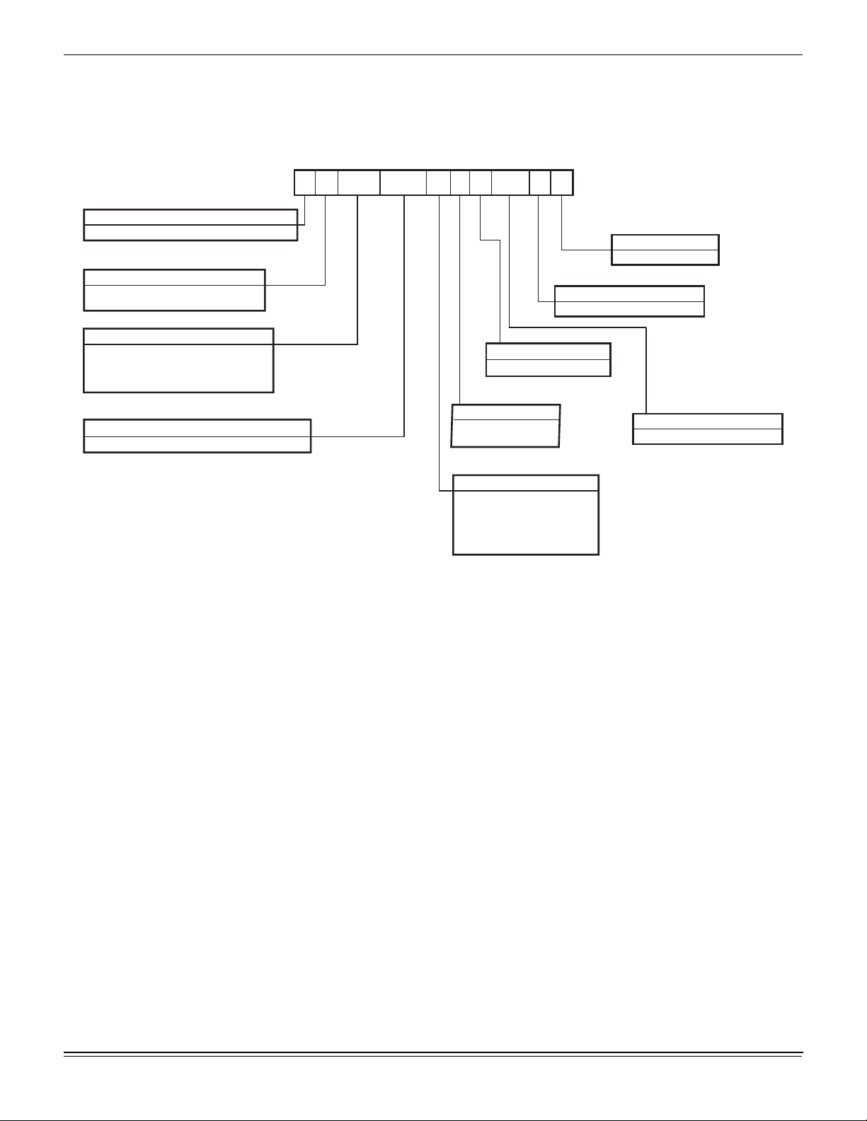
Nomenclature
Configured Split Air Handler Model Number Nomenclature
520413-BIM-A-0209
Product Category
N = Split System, Air Handler, AC & HP, R-410A
Product Identifier
H = Standard Efficiency, 2-Pipe, R-410A
J = Standard Efficiency, 4-Pipe, R-410A
Nominal Cooling Capacity - MBH
-07 = 7.5 Ton
-10 = 10 Ton
-15 = 15 Ton
-20 = 20 Ton
Heat Type & Nominal Heat Capacity
C00 = Cooling Only
N
H
-20
C00 B
S
A
A = None
Voltage
S = 208/230/460-3-60
X = 575-3-60
B = 1.5 HP Motor
C = 2.0 HP Motor
D = 3 HP Motor
E = 5 HP Motor
F = 7.5 HP Motor
2
AA
Installation Options
Airflow
A
Product Style
A = Style A
Product Generation
1 = First Generation
Product Options
AA = None
Johnson Controls Unitary Products 3
Page 4
520413-BIM-A-0209
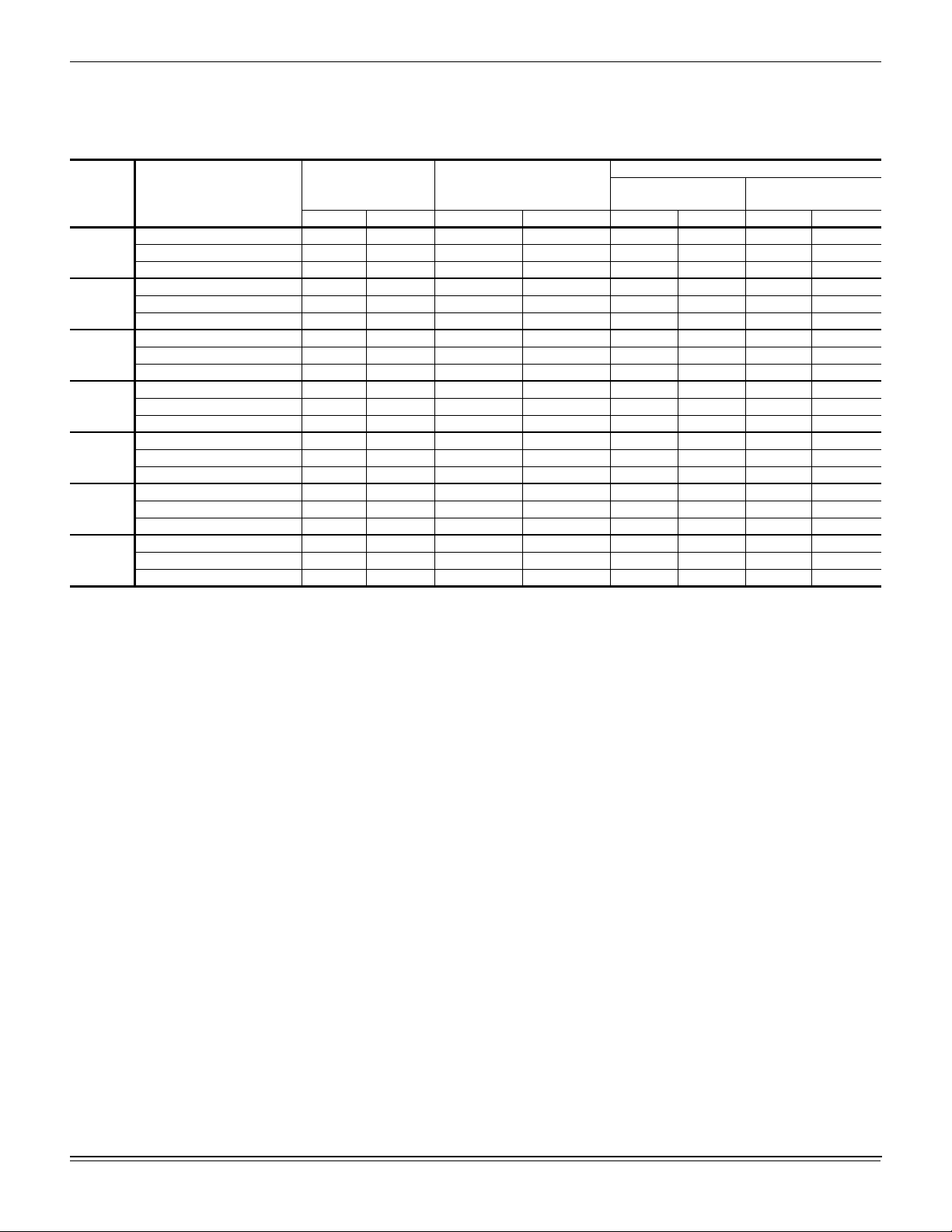
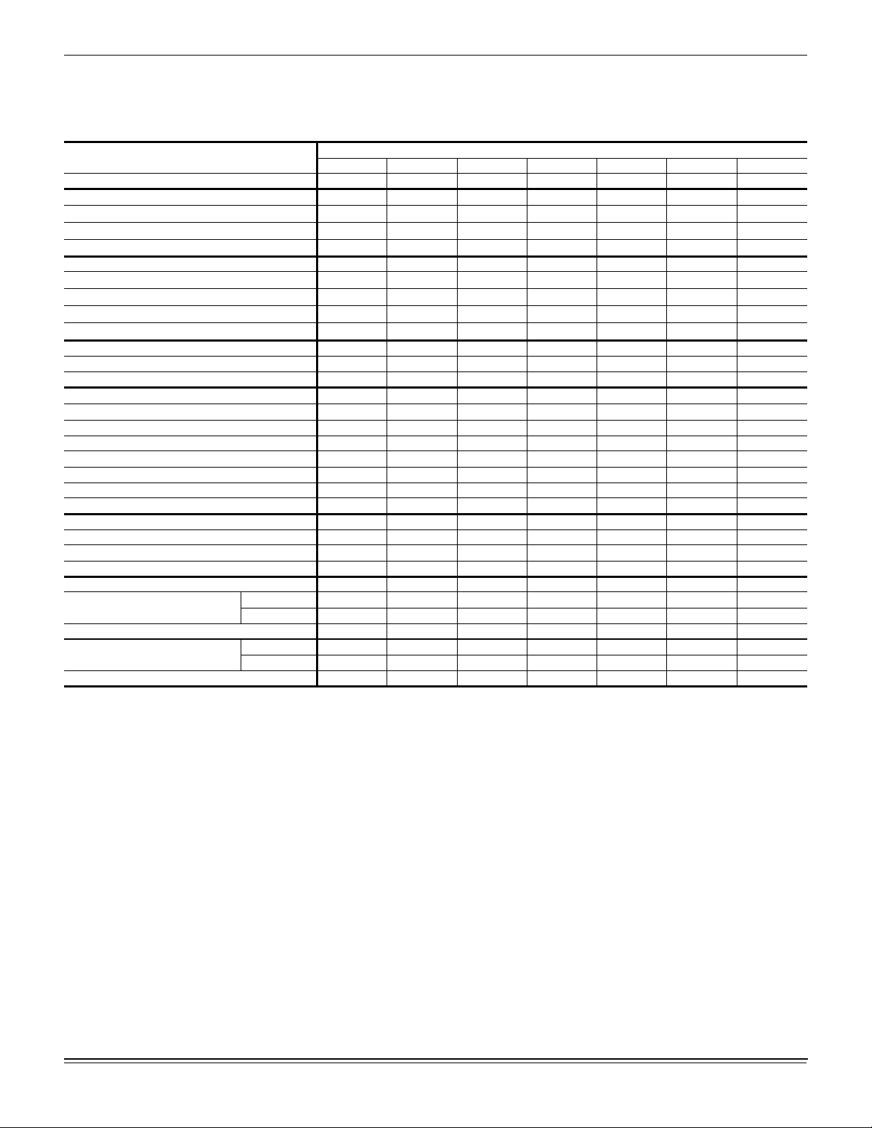
Unit Application Data
Table 1: Unit Application Data Indoor
Entering Air Temperature Degrees °F
Model Power Supply Voltage
208/230-3-60 187 253 2,250 3,750 65/57 90/77 40 80
NH-07
NH-10
NJ-10
NH-15
NJ-15
NH-20
NJ-20
1. Heating Min/Max temperatures apply to steam and hot water coils. NOTE: Do not apply steam to hot water coils.
460-3-60 414 506 2,250 3,750 65/57 90/77 40 80
575-3-60 540 630 2,250 3,750 65/57 90/77 40 80
208/230-3-60 187 253 3,000 5,000 65/57 90/77 40 80
460-3-60 414 506 3,000 5,000 65/57 90/77 40 80
575-3-60 540 630 3,000 5,000 65/57 90/77 40 80
208/230-3-60 187 253 3,000 5,000 65/57 90/77 40 80
460-3-60 414 506 3,000 5,000 65/57 90/77 40 80
575-3-60 540 630 3,000 5,000 65/57 90/77 40 80
208/230-3-60 187 253 4,500 7,500 65/57 90/77 40 80
460-3-60 414 506 4,500 7,500 65/57 90/77 40 80
575-3-60 540 630 4,500 7,500 65/57 90/77 40 80
208/230-3-60 187 253 4,500 7,500 65/57 90/77 40 80
460-3-60 414 506 4,500 7,500 65/57 90/77 40 80
575-3-60 540 630 4,500 7,500 65/57 90/77 40 80
208/230-3-60 187 253 6,000 10,000 65/57 90/77 40 80
460-3-60 414 506 6,000 10,000 65/57 90/77 40 80
575-3-60 540 630 6,000 10,000 65/57 90/77 40 80
208/230-3-60 187 253 6,000 10,000 65/57 90/77 40 80
460-3-60 414 506 6,000 10,000 65/57 90/77 40 80
575-3-60 540 630 6,000 10,000 65/57 90/77 40 80
Voltage Variation Supply Air Range CFM
Min. Max. Min. Max. Min. Max. Min. Max.
Cooling
DB/WB
Heating DB
1
4 Johnson Controls Unitary Products
Page 5
520413-BIM-A-0209
Physical Data Indoor Unit
Table 2: Physical Data Indoor Unit
Component
Nominal Tonnage 7 1/2 10 10 15 15 20 20
DIMENSIONS (inches)
Length
Width
Height
WEIGHTS (lb)
Unit Shipping
Unit Operating With
Standard Motor and Drive
High Static Motor and Drive
INDOOR BLOWER (Forward Curve)
Diameter x Width 12 x 12 15 x 15 15 x 15 18 x 18 18 x 18 15 x 15 15 x 15
Quantity 1111122
NH-07 NH-10 NJ-10 NH-15 NJ-15 NH-20 NJ-20
56.0 56.0 56.0 74.5 74.5 98.5 98.5
30.0 30.0 30.0 33.0 33.0 30.0 30.0
65.0 65.0 65.0 75.0 75.0 65.0 65.0
405 512 512 681 681 874 874
381 468 468 632 632 816 816
385 492 492 661 661 854 854
INDOOR COIL
Face area (Sq. Ft.) 10.6 10.6 10.6 18.3 18.3 20.0 20.0
Rows 3443443
Fins per inch 15 15 15 15 15 15 15
Tube diameter 3/8 3/8 3/8 3/8 3/8 3/8 3/8
Circuitry Type Interfaced Interfaced Interfaced Interfaced Interfaced Interfaced Interfaced
Refrigerant Control TXV TXV TXV TXV TXV TXV TXV
Operating Charge (lb) 4 6 6 10 10 10 10
SYSTEM DATA
No. Refrigeration Circuits 1121212
Suction Line OD (in.) 1 1/8 1 3/8 1 1/8 1 5/8 1 1/8 1 5/8 1 3/8
Liquid Line OD (in.) 5/8 7/8 5/8 7/8 5/8 7/8 7/8
FILTERS
Size and Quantity Per Model (In.) 16 x 25 x 2 4 4 4 --- --- 8 8
20 x 24 x 2 --- --- --- 6 6 --- --Face area (Sq. Ft.) 11.1 11.1 11.1 20.0 20.0 22.2 22.2
Size and Quantity Per Model (In.) 16 x 25 x 4 4 4 4 --- --- 8 8
18 x 24 x 4 --- --- --- 6 6 --- ---
Face area (Sq. Ft.) 11.1 11.1 11.1 18.0 18.0 22.2 22.2
Models
Air Discharge Conversion
6. Rotate the blower section and mate it to the hole left when
the panel was removed in Step 5.
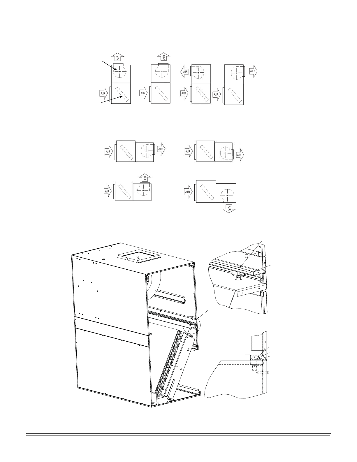
These units are shipped for Vertical Airflow operation as seen in
Figure 1 Positions 1 thru 4, but may be converted for Horizontal
Airflow operation illustrated in Figure 2 Positions 1 thru 4.
Conversion Example:
7. Bolt and clamp the two sections together.
8. Place the panel remove
1. d in Step 5 on top of the evaporator section and screw
together.
Convert Vertical Airflow Position 1 to Horizontal Airflow Position
1 as follows:
NOTE: 1 inch blower duct flange shipped with air handler.
1. Remove the front blower panel from the blower section and
set aside. This allows access to the clamps that hold the
blower section to the evaporator section.
2. Remove the bolts and clamp angles that hold the coil
section and blower section together.
3. Place the panel removed in Step 1 on top of the blower
section and screw together.
4. Set the blower section aside.
5. Remove the evaporator section rear panel and set aside.
Johnson Controls Unitary Products 5
Page 6
520413-BIM-A-0209
BLOWER
EVAPORATOR
COIL
POSITION
1
Figure 1: Vertical Airflow Arrangements
POSITION
2
POSITION
3
POSITION
4
POSITION
POSITION
Figure 2: Horizontal Airflow Arrangements
1
2
3
POSITION
4
3/8” x 1 1/4” Bolt
Clamp
See Detail A
Detail A
POSITION
Bolt
Lock
Flat
Washer
Detail B
Cabinet Clamp Assembly
Typical Cabinet Clamp Assembly
Figure 3: Typical Cabinet Clamp Assembly
6 Johnson Controls Unitary Products
Page 7
Unit Installation
Location
These evaporator blowers are not designed for outdoor
installation. They must be located inside a building structure,
either inside or outside the conditioned space where they are
protected from rain and other moisture.
The unit should be located as close to the condensing unit as
practical and positioned to minimize bends in the refrigerant
piping.
Units being installed vertically or horizontally can be set directly
on a floor or platform, or supported by metal or wooden beams.
Rigging
Care must be taken when moving the unit. Do not remove any
packaging until the unit is near the place of installation.
SPREADER BARS SHOULD BE USED BETWEEN THE
SLINGS TO PREVENT CRUSHING THE UNIT FRAME OR
PANELS. When preparing to move the unit, always determine
the center of gravity of the unit in order to equally distribute the
weight. Rig the unit by attaching chain or cable slings around
the bottom skid. A lift truck may be used to raise a unit to a
suspended location. Refer to Table 4 for unit weights.
520413-BIM-A-0209
Clearances
Table 3: Minimum Clearances
Minimum Clearances
Top with Supply Air Opening
Front with Return Air Opening 24”
Right Side with Access for Piping, Power &
Control Wiring Connections
Left Side 24”
3
Rear
4
Bottom
1. This dimension will vary if an electric heater, a supply air plenum or a
base is used.
2. This dimension is required for normal installation and service.
3. Although no clearance is required for service and operation, some
clearance may be required for routing the power and control wiring.
4. Allow enough clearance to trap the condensate drain line.
NOTE: If the coil has t o be removed, the blowe r section can be unbolted
and set aside and the coil can be lifted out the top of the
evaporator section.
A 24-inch clearance is required on the end with the piping
connections and the supply air blower motor to properly service
and maintain the unit.
Some clearance will also be required for the duct and power
wire connections.
1
2
24”
24”
N/A
N/A
Johnson Controls Unitary Products 7
Page 8
520413-BIM-A-0209
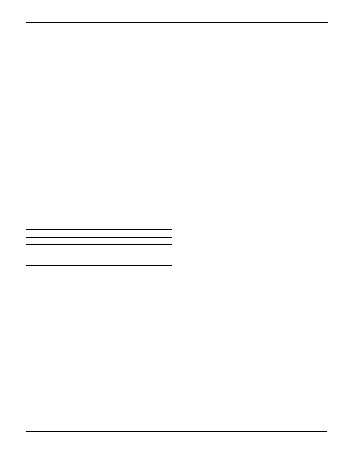
Mounting
The split air handling units can be applied in various horizontal
positions. Figure 4 shows recommended suspension rigging
using properly sized all-thread and metal c-channel. All
END VIEW
components to suspend an AHU must be field supplied. Please
refer to the units total weight, center of gravity and corner
weights (Horizontal position) shown in the appropriate table for
proper support sizing.
MOUNTING DETAIL
All Thread
Steel Rod
Mounting
Bracket
Flat Washer /
Lock Washer
and Nut
Steel Cchannel
SIDE VIEW
Figure 4: Typical Suspension of AHU’s From Ceiling
8 Johnson Controls Unitary Products
Page 9

Table 4: Corner Weights & Center of Gravity NH/NJ Unit
Model Options
Vertical Airflow
NH-07
NH/NJ-10
NH/NJ-15
NH/NJ-20
Std. Mtr. and Drv. 357 381 30 30 102 102 88 88 68 68 68 59 59 59
High Static Mtr. and Drv. 357 385 30 30 103 103 89 89 69 69 69 60 60 60
Std. Mtr. and Drv. 422 468 30 30 125 125 109 109 84 84 84 72 72 72
High Static Mtr. and Drv. 422 492 31 29 123 132 123 115 81 85 89 83 79 76
Std. Mtr. and Drv. 560 632 36 36 139 167 178 148 90 101 115 122 108 96
High Static Mtr. and Drv. 560 661 36 35.5 143 172 189 157 93 104 118 130 114 102
Std. Mtr. and Drv. 715 816 32 48 186 212 223 195 121 132 145 152 139 127
High Static Mtr. and Drv. 715 854 32 47 190 217 238 208 124 135 148 162 148 136
Horizontal Airflow
NH-07
NH/NJ-10
NH/NJ-15
NH/NJ-20
Std. Mtr. and Drv. 357 381 15 30 102 102 88 88 68 68 68 59 59 59
High Static Mtr. and Drv. 357 385 15 30 103 103 89 89 69 69 69 60 60 60
Std. Mtr. and Drv. 422 468 15 30 125 125 109 109 84 84 84 72 72 72
High Static Mtr. and Drv. 422 492 15.5 29 123 132 123 115 81 85 89 83 79 76
Std. Mtr. and Drv. 560 632 18 36 139 167 178 148 90 101 115 122 108 96
High Static Mtr. and Drv. 560 661 18 35.5 143 172 189 157 93 104 118 130 114 102
Std. Mtr. and Drv. 715 816 16 48 186 212 223 195 121 132 145 152 139 127
High Static Mtr. and Drv. 715 854 16 47 190 217 238 208 124 135 148 162 148 136
Weight (lbs.) Center of Gravity (in.) 4 Point Load Location (lbs.) 6 Point Load Location (lbs.)
Shipping Operating X Y A B C D A B C D E F
520413-BIM-A-0209
FRONT
WIDTH
LEFT
A
A
DIM Y
F
D
DIM X
VERTICAL POSITION
B
E
LENGTH
RIGHT
CG
LEFT
B
C
WIDTH
REAR
FRONT
D
C
DIM Y
A
A
F
D
DIM X
HORIZONTAL POSITION
B
E
LENGTH
RIGHT
CG
B
C
REAR
D
C
Johnson Controls Unitary Products 9
Page 10
520413-BIM-A-0209
Table 5: Accessory Operating Weight Distribution (Lbs)
ACCESSORY
2
BASE
HOT WATER COIL
STEAM COIL
1.These weights should be added to each point load in table 4.
2.This accessory can only be applied on units installed in the vertical position.
NH-07 NH/NJ-10 NH/NJ-15 NH/NJ-20
1
25 25 30 45
35 35 45 35
30 30 35 50
Duct Connections
Ductwork should always be suspended with hangers or
supported by legs. It should never be fastened directly to the
building structure.
Allow clearance around ducts for safety in the handling of
heated air and for insulation when required.
Insulation
Ductwork insulation should meet the following criteria:
• Be used when ducts pass through an unconditioned
space in the cooling season or through an unheated
space during the heating season.
• Include a vapor barrier around the outside to prevent the
absorption of moisture.
• Be no less than 2 inches thick with a weatherproof coating
when applied to ducts exposed to outdoor conditions.
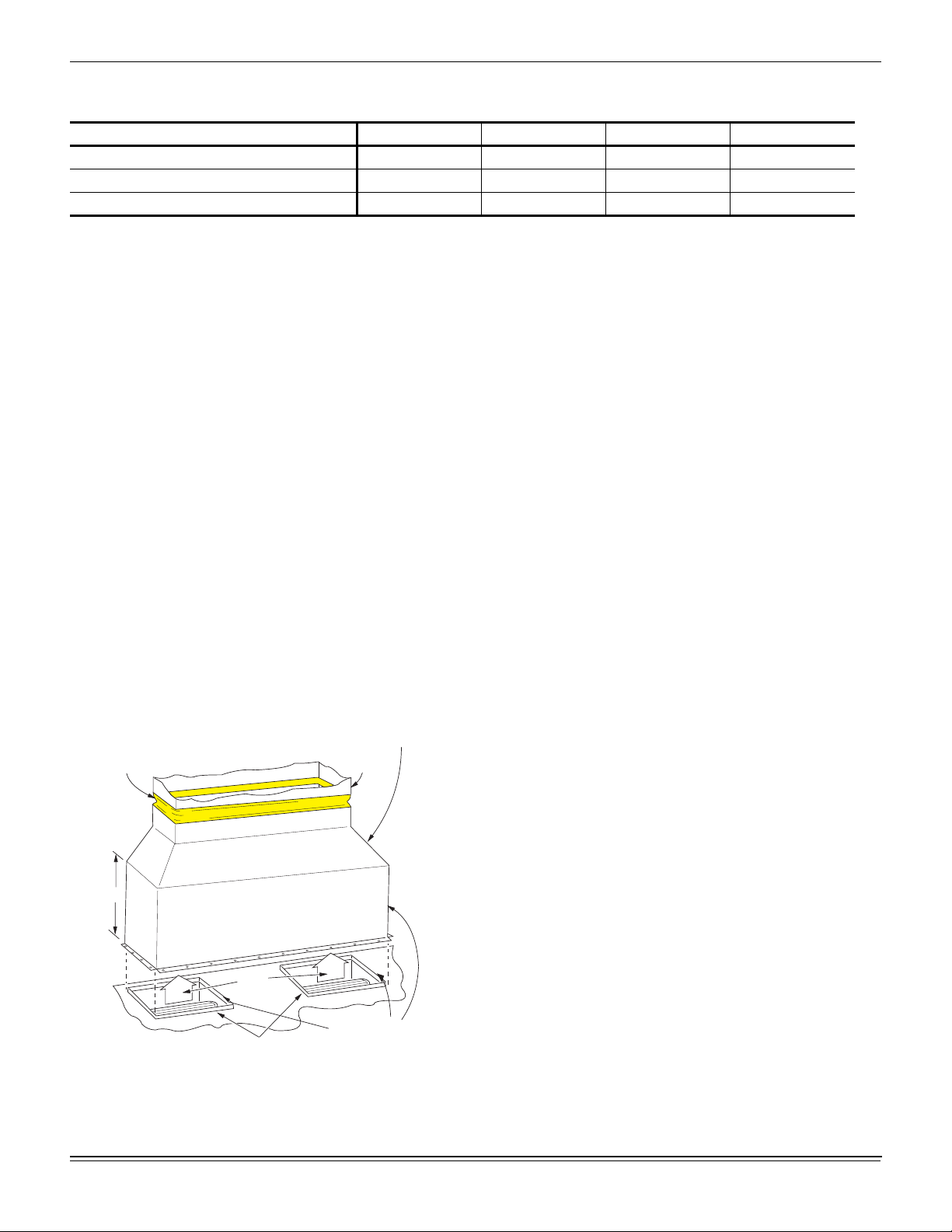
Supply Air Ducts
See Figure 5 for suggested method of connecting supply air
ductwork. Non-flammable material collars should be used to
minimize the transmission of noise and/or vibration.
DUCT
NON-FLAMMABLE
COLLAR
24"
AIR
OUTLET
BLOWER
GASKETS
(BY INSTALLER)
TRANSITION
DUCT
FLANGED DUCT
CONNECTION
(Factory Furnished,
Field Installed )
Figure 5: Suggested Method For Co nn e cti ng Ductw ork
10 Johnson Controls Unitary Products
Page 11
520413-BIM-A-0209
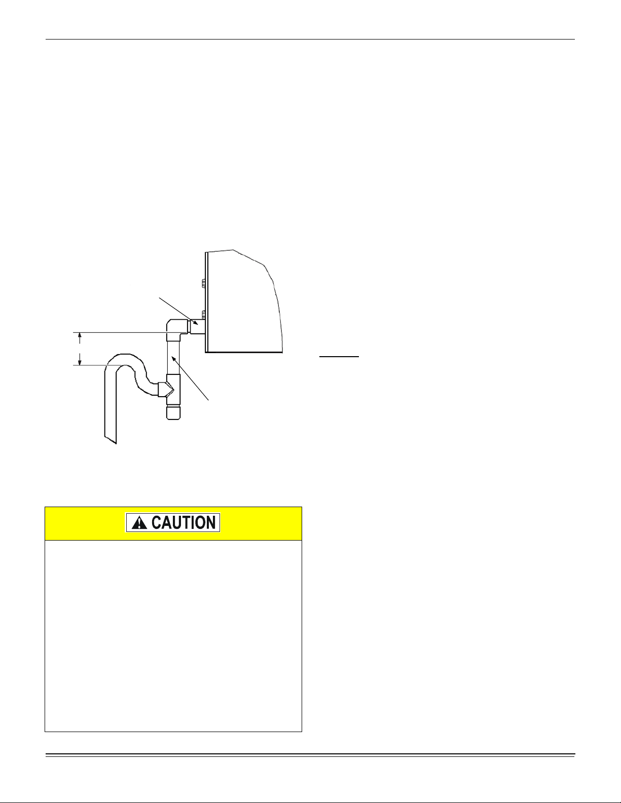
Drain Connections
All drain lines MUST be trapped and located so they will not be
exposed to freezing temperatures.
All evaporator blower units have a 3/4” PVC condensate stub at
the end of a double sloped drain pan. The drain pan is
removable and reversible, It can be unscrewed and slid out
from one side of the evaporator section and installed in the
other end.
Drain piping should be constructed as shown in Figure 6. The
3-inch dimension must equal or exceed the negative static
pressure developed by the supply air blowers. If it does not, the
condensate will not drain properly and may overflow the drain
pan.
¾” PVC
STUB
3" MINIMUM
Line Sizing
When sizing refrigerant pipe for a split-system air conditioner,
check the following:
1. Suction line pressure drop due to friction.
2. Liquid line pressure drop due to friction.
3. Suction line velocity for oil return.
4. Liquid line pressure drop due to vertical rise. For certain
piping arrangements, different sizes of suction line pipe
may have to be used. The velocity of the refrigerant vapor
must always be great enough to carry the oil back to the
compressor.
5. Evaporator Located Below Condenser - On a split
system where the evaporator blower is located below the
condenser, the suction line must be sized for both pressure
drop and for oil return.
6. Condenser Located Below Evaporator - When the
condenser is located below the evaporator blower, the
liquid line must be designed for the pressure drop due to
both friction loss and vertical rise. If the pressure drop due
to vertical rise and friction exceeds 40 psi, some refrigerant
will flash before it reaches the thermal expansion valve.
Flash gas
:
FIELD SUPPLIED
Figure 6: Recommended Drain Piping
Refrigerant Mains
This Split-System (Air Condensing / Heat Pump / Air
Handling) unit is one component of an entire system. As
such it requires specific application considerations with
regard to the rest of the system (air handling unit, duct
design, condensing unit, refrigerant piping and control
scheme).
Failure to properly apply this equipment with the rest of
the system may result in premature failure and/or
reduced performance / increased costs. Warranty
coverage specifically excludes failures due to improper
application and Unitary Products specifically disclaims
any liability resulting from improper application.
Please refer to the equipment Technical Guide,
Installation Manual and the piping applications bulletin
247077 or call the applications department for Unitary
Products @ 1-877-UPG-SERV for guidance.
1. Increases the liquid line pressure loss due to friction that in
turn causes further flashing.
2. Reduces the capacity of the refrigerant control device
which starves the evaporator.
3. Erodes the seat of the refrigerant control device.
4. Causes erratic control of the refrigerant entering the
evaporator.
Take Adequate Precautions
Many service problems can be avoided by taking adequate
precautions to provide an internally clean and dry system and
by using procedures and materials that conform to established
standards.
Use hard drawn copper tubing where no appreciable amount of
bending around pipes or other obstructions is necessary. If soft
copper is used, care should be taken to avoid sharp bends that
may cause a restriction. Pack fiberglass insulation and a
sealing material such as permagum around refrigerant lines
where they penetrate a wall to reduce vibrations and to retain
some flexibility.
Support all tubing at minimum intervals with suitable hangers,
brackets or clamps.
Braze all copper-to-copper joints with Silfos-5 or equivalent
brazing material. Do not use soft solder. Insulate all suction
lines with a minimum of 1/2" ARMAFLEX or equivalent. Liquid
lines exposed to direct sunlight and/or high temperatures must
also be insulated. Never solder suction and liquid lines
together. They can be taped together for convenience and
Johnson Controls Unitary Products 11
Page 12

520413-BIM-A-0209
support purposes, but they must be completely insulated from
each other.
The liquid and suction service ports on the condenser section
permit leak testing, evacuation, and partial charging of the field
piping and the evaporator without disturbing refrigerant stored
in the condenser during initial installation.
Before beginning installation of the main lines, be sure that the
evaporator section has not developed a leak in transit. Check
pressure at the Schrader valve located on the header of each
coil. If pressure still exists in the system, it can be assumed to
be leak free. If pressure DOES NOT exist the section will need
to be repaired before evacuation and charging is performed.
A filter-drier MUST be field-installed in the liquid line of every
system to prevent dirt and moisture from damaging the system.
Properly sized filter-driers are shipped with each condensing
section.
NOTE: Installing a filter-drier does not eliminate the need for
the proper evacuation of a system before it is charged.
A field-installed moisture indicating sight-glass should be
installed in the liquid line(s) between the filter-drier and the
evaporator coil. The moisture indicating sight-glass can be used
to check for excess moisture in the system or used as a visual
means to verify refrigerant charge.
Both condenser and evaporator sections have copper sealing
disks brazed over the end of liquid and suction connections.
The temperature required to make or break a brazed joint is
high enough to cause oxidation of the copper unless an inert
atmosphere is provided.
connections of the main lines. Repeat for the liquid line valve
body.
Never remove a cap from an access port unless the
valve is fully back-seated with its valve stem in the
maximum counter-clockwise position because the
refrigerant charge will be lost. Always use a refrigeration
valve wrench to open and close these service valves.
Connect the main liquid line to the liquid line connection on the
condenser section, while maintaining a flow of Nitrogen. Cool
the valve body and replace the Schraded valve stem on the
service port of the liquid line service valve.
Install the liquid line from the condensing unit to the evaporator
liquid connection, maintaining a flow of nitrogen during all
brazing operations.
The filter-drier and sight glass must be located in this line, close
to the evaporator.
Connect a low-pressure nitrogen source to the Schrader valve
located on the evaporator section coil headers. Drill a small
hole in the sealing disks, the flow of Nitrogen will prevent any
debris from entering the system. Unbraze both liquid and
suction sealing disks and prepare the joints for connections of
the main lines.
Connect the main liquid line to the liquid line connection on the
evaporator section, while maintaining a flow of Nitrogen.
NOTE: Dry Nitrogen should flow through the system at all
times when heat is being applied and until the joint has
cooled. The flow of Nitrogen will prevent oxidation of
the copper lines during installation.
Always drill a small hole in sealing disks before unbrazing to
prevent the pressure in the line from blowing them off.
NOTE: Solenoid and hot gas bypass valves (if used) should be
opened manually or electrically duri ng brazing or
evacuating.
NOTE: Schrader valves located on unit service valves should
have their stem removed during brazing to prevent
damage to the valve.
Start Installation
Start Installation of main lines at the condensing section. Verify
the service valves are fully seated by screwing the stem of both
valves down into the valve body until it stops. Remove the
Schraded valve stem and connect a low-pressure nitrogen
source to the service port on the suction line valve body. Drill a
small hole in the sealing disk; the flow of Nitrogen will prevent
any debris from entering the system. Wrap the valve body with
a wet rag to prevent overheating during the brazing process.
Overheating the valve will damage the valve seals. Unbraze the
sealing disk, cool the valve body and prepare the joint for
Make the suction line connection at the evaporator and run the
line to the condensing unit. Connect the main suction line to the
suction line connection on the condenser section, while
maintaining a flow of Nitrogen. Cool the valve body and replace
the Schraded valve stem on the service port of the liquid line
service valve.
Once the brazing process is complete, leak testing should be
done on all interconnecting piping and the evaporator befo re
proper evacuation to 500 microns is performed. Once the line
set and evaporator section is properly evacuated the service
valves can be opened and the condensing unit is now ready to
charge with the appropriate weight of refrigerant.
The correct refrigerant pressures are indicated as shown in
Figures 10 through 13.
12 Johnson Controls Unitary Products
Page 13

This system uses R-410A Refrigerant which operates at
higher pressures than R-22. No other refrigerant may be
used in this system. Gage sets, hoses, refrigerant
containers and recovery systems must be designed to
handle R-410A. If you are unsure, consult the
equipment manufacturer. Failure to use R-410A
compatible servicing equipment may result in property
damage or injury.
520413-BIM-A-0209
wired to operate in a similar fashion as described on pages 14
and 15.
NOTE: See Liquid Line Solenoid Wiring on page 15.
Air System Adjustment
Refer to Tables 8 thru 18 to adjust the air system.
Electrical Connections
The electric box ships complete with contractor, transformer,
relays, circuit breaker and terminal block for making field
connections.
Refer to Typical Unit Wiring Diagrams.
Wear safety glasses and gloves when handling
refrigerants. Failure to follow this warning can cause
serious personal injury.
NOTE: This instruction covers the installation and operation of
the basic condensing unit. For refrigerant piping
installation instructions refer to document 247077
"Application Data - General Piping Recommendations
for Split System Air Conditioning and Heat Pumps".
Expansion Valve Bulb Installation
Thermal expansion valve bulbs on the blower units are not
factory-installed in its final locati o n s ; Th ey are only temporarily
taped for shipment. The bulb for system one must be fastened
in a 4 o'clock and/or 8 o'clock position to the system one suction
line leaving the evaporator coil after piping connections are
made. Repeat the procedure for system two, locating the bulbs
in a 4 o'clock and/or 8 o'clock position to the system two suction
line. Use the bulb clamps from the bag taped to the suction
connection inside the blower unit.
NOTE: Ensure the TXV bulbs are not crossed between
systems. Undesirable performance and possible
compressor damage may occur.
Liquid Line Solenoids
Install a power supply to meet the requirements listed in
Electric Data Table 6.
Provide a disconnect switch and fusing as required.
Install interconnecting control wiring between condensing
section, evaporator blower and room thermostat.
The unit is shipped with factory installed, normally closed, liquid
line solenoid valves. When the solenoid coil is energized with a
24-volt signal, the valve will open.
During brazing operations, the valves should be placed in the
OPEN position by removing the stem cap with a 9/16” wrench,
then rotating the exposed valve stem inward (CLOCKWISE),
approximately 10-12 full turns (from the fully CLOSED position),
using a 4” adjustable wrench.
The valve stems should be returned to the CLOSED
(COUNTER-CLOCKWISE) position prior to the unit’s operation.
The sequence of operation applies to the PC/PD and YC/YD
condensing units and NH/NJ air handlers when applied as a
matched system. Non-matched systems will have to be field
Johnson Controls Unitary Products 13
Page 14

520413-BIM-A-0209
S1
G1
S1 G1
S2
S2
G2
C
CG2
Figure 7: Typical Field Wiring Diagram - NH-07 Unit
SINGLE STAGE
THERMOSTAT
14 Johnson Controls Unitary Products
Page 15

S1
S1
G1
G1
S2
S2
G2
G2
520413-BIM-A-0209
C
C
Figure 8: Typical Field Wiring Diagram - NH/NJ-10 Thru -20 Unit
Figure 9: NH/NJ-10 Thru -20 Liquid Line Solenoid Wiring
Johnson Controls Unitary Products 15
Page 16

520413-BIM-A-0209
Electrical Data
Table 6: Electrical Data - Electric Heat
Supply
Motor HP Power Supply
208-3-60 5.0
230-3-60 5.0
1.5
460-3-60 2.5
575-3-60 2.0
208-3-60 6.3
230-3-60 6.3
2.0
460-3-60 3.2
575-3-60 2.4
Blower
Motor
FLA Model KW Stages Amps
Electric Heat Option
NH-07C00B
None --- --- --- 11.3 15
10 KW 7.5 1 20.8 32.1 35
16 KW 12 2 33.4 44.6 45
26 KW 19.5 2 54.2 65.5 70
36 KW 27 2 75.1 86.3 90
None --- --- --- 11.3 15
10 KW 10 1 24.1 35.3 40
16 KW 16 2 38.5 49.7 50
26 KW 26 2 62.5 73.8 80
36 KW 36 2 86.6 97.9 100
None --- --- --- 5.6 15
10 KW 10 1 12.0 17.7 20
16 KW 16 2 19.2 24.9 25
26 KW 26 2 31.3 36.9 40
36 KW 36 2 43.3 48.9 50
None --- --- --- 4.5 15
10 KW 10 1 9.6 14.1 15
16 KW 16 2 15.4 19.9 20
26 KW 26 2 25.0 29.5 30
36 KW 36 2 34.6 39.1 40
NH-07C00C, NH/NJ-10C00C
None --- --- --- 14.2 15
10 KW 7.5 1 20.8 35.0 40
16 KW 12 2 33.4 47.5 50
26 KW 19.5 2 54.2 68.4 70
36 KW 27 2 75.1 89.2 90
None --- --- --- 14.2 15
10 KW 10 1 24.1 38.2 40
16 KW 16 2 38.5 52.7 60
26 KW 26 2 62.5 76.7 80
36 KW 36 2 86.6 100.8 110
None --- --- --- 7.2 15
10 KW 10 1 12.0 19.2 20
16 KW 16 2 19.2 26.4 30
26 KW 26 2 31.3 38.5 40
36 KW 36 2 43.3 50.5 60
None --- --- --- 5.4 15
10 KW 10 1 9.6 15.0 20
16 KW 16 2 15.4 20.8 25
26 KW 26 2 25.0 30.4 35
36 KW 36 2 34.6 40.0 45
MCA
(Amps)
1
Max Fuse
Breaker
(Amps)
3
Size
2
/
16 Johnson Controls Unitary Products
Page 17

Table 6: Electrical Data - Electric Heat (Continued)
Supply
Motor HP Power Supply
208-3-60 9.6
230-3-60 9.6
3.0
460-3-60 4.7
575-3-60 3.6
208-3-60 14.0
230-3-60 14.0
5.0
460-3-60 7.0
575-3-60 5.2
208-3-60 14.0
230-3-60 14.0
5.0
460-3-60 7.0
575-3-60 5.2
Blower
Motor
FLA Model KW Stages Amps
10 KW 7.5 1 20.8 42.4 45
16 KW 12 2 33.4 55.0 60
26 KW 19.5 2 54.2 75.8 80
36 KW 27 2 75.1 96.7 100
10 KW 10 1 24.1 45.7 50
16 KW 16 2 38.5 60.1 70
26 KW 26 2 62.5 84.1 90
36 KW 36 2 86.6 108.2 110
10 KW 10 1 12.0 22.6 25
16 KW 16 2 19.2 29.8 30
26 KW 26 2 31.3 41.8 45
36 KW 36 2 43.3 53.9 60
10 KW 10 1 9.6 17.7 20
16 KW 16 2 15.4 23.5 25
26 KW 26 2 25.0 33.1 35
36 KW 36 2 34.6 42.7 45
10 KW 7.5 1 20.8 52.3 60
16 KW 12 2 33.4 64.9 70
26 KW 19.5 2 54.2 85.7 90
36 KW 27 2 75.1 106.6 110
50 KW 37.6 2 104.2 135.7 150
10 KW 10 1 24.1 55.6 60
16 KW 16 2 38.5 70.0 70
26 KW 26 2 62.5 94.0 100
36 KW 36 2 86.6 118.1 125
50 KW 50 2 120.3 151.8 175
10 KW 10 1 12.0 27.8 30
16 KW 16 2 19.2 35.0 35
26 KW 26 2 31.3 47.0 50
36 KW 36 2 43.3 59.1 60
50 KW 50 2 60.1 75.9 80
10 KW 10 1 9.6 21.3 25
16 KW 16 2 15.4 27.1 30
26 KW 26 2 25.0 36.7 40
36 KW 36 2 34.6 46.3 50
50 KW 50 2 48.1 59.8 60
20 KW 15 1 41.7 73.2 80
32 KW 24 2 66.7 98.2 100
52 KW 39.1 2 108.4 139.9 150
20 KW 20 1 48.1 79.6 80
32 KW 32 2 77.0 108.5 110
52 KW 52 2 125.1 156.6 175
20 KW 20 1 24.1 39.8 40
32 KW 32 2 38.5 54.2 60
52 KW 52 2 62.5 78.3 80
20 KW 20 1 19.2 30.9 35
32 KW 32 2 30.8 42.5 45
52 KW 52 2 50.0 61.7 70
NH/NJ-10C00D, NH/NJ-15C00D
None --- --- --- 21.6 25
None --- --- --- 21.6 25
None --- --- --- 10.6 15
None --- --- --- 8.1 15
None --- --- --- 31.5 35
None --- --- --- 31.5 35
None --- --- --- 15.8 20
None --- --- --- 11.7 15
None --- --- --- 31.5 35
None --- --- --- 31.5 35
None --- --- --- 15.8 20
None --- --- --- 11.7 15
Electric Heat Option
NH/NJ-15C00E
NH/NJ-20C00E
MCA
(Amps)
520413-BIM-A-0209
1
Max Fuse
Breaker
(Amps)
3
Size
2
/
Johnson Controls Unitary Products 17
Page 18

520413-BIM-A-0209
Table 6: Electrical Data - Electric Heat (Continued)
Supply
Motor HP Power Supply
208-3-60 19.2
230-3-60 19.2
7.5
460-3-60 9.6
575-3-60 7.8
1. Minimum Circuit Ampacity.
2. Dual Element, Time Delay Type.
3. HACR type per NEC.
Blower
Motor
FLA Model KW Stages Amps
None --- --- --- 43.2 45
20 KW 15 1 41.7 84.9 90
32 KW 24 2 66.7 109.9 110
52 KW 39.1 2 108.4 151.6 175
None --- --- --- 43.2 45
20 KW 20 1 48.1 91.3 100
32 KW 32 2 77.0 120.2 125
52 KW 52 2 125.1 168.3 175
None --- --- --- 21.6 25
20 KW 20 1 24.1 45.7 50
32 KW 32 2 38.5 60.1 70
52 KW 52 2 62.5 84.1 90
None --- --- --- 17.6 20
20 KW 20 1 19.2 36.8 40
32 KW 32 2 30.8 48.3 50
52 KW 52 2 50.0 67.6 70
Electric Heat Option
NH/NJ-20C00F
MCA
(Amps)
2
3
(Amps)
/
Size
1
Max Fuse
Breaker
CFM Static Pressure and Power-Altitude and Temperature
Corrections
The information below should be used to assist in application of
product when being applied at altitudes at or exceeding 1000
feet above sea level.
The air flow rates listed in the standard blower performance
tables are based on standard air at sea level. As the altitude or
temperature increases, the density of air decreases. In order to
use the indoor blower tables for high altitude applications,
certain corrections are necessary.
A centrifugal fan is a "constant volume" device. This means
that, if the rpm remains constant, the CFM delivered is the
same regardless of the density of the air. However, since the air
at high altitude is less dense, less static pressure will be
generated and less power will be required than a similar
application at sea level. Air density correction factors are shown
in Table 7 and Figure 10.
18 Johnson Controls Unitary Products
Page 19

520413-BIM-A-0209
Table 7: Altitude/Temperature Correction Factors
Air
Temp.
40 1.060 1.022 0.986 0.950 0.916 0.882 0.849 0.818 0.788 0.758 0.729
50 1.039 1.002 0.966 0.931 0.898 0.864 0.832 0.802 0.772 0.743 0.715
60 1.019 0.982 0.948 0.913 0.880 0.848 0.816 0.787 0.757 0.729 0.701
70 1.000 0.964 0.930 0.896 0.864 0.832 0.801 0.772 0.743 0.715 0.688
80 0.982 0.947 0.913 0.880 0.848 0.817 0.787 0.758 0.730 0.702 0.676
90 0.964 0.929 0.897 0.864 0.833 0.802 0.772 0.744 0.716 0.689 0.663
100 0.946 0.912 0.880 0.848 0.817 0.787 0.758 0.730 0.703 0.676 0.651
0 1000 2000 3000 4000 5000 6000 7000 8000 9000 10000
1.100
1.050
1.000
0.950
0.900
0.850
0.800
Correction Factor
0.750
0.700
0.650
Altitude (Ft.)
Sea Level
1000 ft
2000 ft
3000 ft
4000 ft
5000 ft
6000 ft
7000 ft
8000 ft
9000 ft
10000 ft
0.600
40 50 60 70 80 90 100
Air Temperature (ºF)
Figure 10: Altitude/Temperature Correction Factors
The examples below will assist in determining the airflow
performance of the product at altitude.
Example 1: What are the corrected CFM, static pressure, and
BHP at an elevation of 5,000 ft. if the blower performance data
is 6,000 CFM, 1.5 IWC and 4.0 BHP?
Solution: At an elevation of 5,000 ft. the indoor blower will still
deliver 6,000 CFM if the rpm is unchanged. However, the
Altitude/Temperature Correction Factors table must be used to
determine the static pressure and BHP. Since no temperature
data is given, we will assume an air temperature of 70°F. The
table shows the correction factor to be 0.832.
Corrected static pressure = 1.5 x 0.832 = 1.248 IWC
Corrected BHP = 4.0 x 0.832 = 3.328
Example 2: A system, located at 5,000 feet of elevation, is to
deliver 6,000 CFM at a static pressure of 1.5". Use the unit
blower tables to select the blower speed and the BHP
requirement.
Solution: As in the example above, no temperature
information is given so 70°F is assumed.
The 1.5" static pressure given is at an elevation of 5,000 ft. The
first step is to convert this static pressure to equivalent sea level
conditions.
Sea level static pressure = 1.5 / .832 = 1.80"
Enter the blower table at 6000 sCFM and static pressure of
1.8". The rpm listed will be the same rpm needed at 5,000 ft.
Suppose that the corresponding BHP listed in the table is 3.2.
This value must be corrected for elevation.
BHP at 5,000 ft. = 3.2 x .832 = 2.66
Johnson Controls Unitary Products 19
Page 20

520413-BIM-A-0209
Drive Selection
1. Determine Upflow or Horizontal supply duct Application.
2. Determine desired airflow.
3. Calculate or measure the amount of external static pressure.
4. Using the operating point, determined from steps 1, 2 & 3, locate this point on the appropriate supply air blower performance
table. (Linear interpolation may be necessary.)
5. Noting the RPM and BHP from step 4, locate the appropriate motor and/or drive on the RPM selection table.
6. Review the BHP compared to the motor options available. Select the appropriate motor and, or drive.
7. Review the RPM range for the motor options available. Select the appropriate drive if multiple drives are available for the
chosen motor.
8. Determine turns open to obtain the desired operation point.
Example
1. 3250 CFM
2. 1.4 iwg
3. Using the supply air blower performance table below, the following data point was located: 1100 RPM & 1.8 BHP.
4. Using the RPM selection table below, Model X is found.
5. 1.8 BHP exceeds the maximum continuous BHP rating of the 1.5 HP motor. The 2 HP motor is required.
6. 1100 RPM is within the range of the 2 HP drives.
7. Using the 2 HP motor and drive, 1 turn open will achieve 1128 RPM.
Airflow Performance
Example Supply Air Blower Performance
Available External Static Pressure - IWG
(CFM)
3000 696 0.9 757 1.1 822 1.2 891 1.3 961 1.3 1019 1.5 1077 1.6 1135 1.8
3250 729 1.1 790 1.3 855 1.4 924 1.5 984 1.6 1042 1.7 1100 1.8 1159 2.0
3500 766 1.3 826 1.5 892 1.6 953 1.6 1010 1.8 1069 1.9 1127 2.0
RPM Selection
Unit Model HP
X
0.20.40.60.81.01.21.41.61.82.0
RPM BHP RPM BHP RPM BHP RPM BHP RPM BHP RPM BHP RPM BHP RPM BHP RPM BHP RPM BHP
Standard 1.5 HP & Drive High Static 2 HP & Drive
Max
BHP
Std. 1.5 1.73 1VL40 AK69 N/A 690 743 796 849 902 955
HS 2 2.30 1VL40 AK56 N/A 863 929 995 1062 1128 1194
Motor
Sheave
Blower
Sheave
6 Turns
Open
5 Turns
Open
4 Turns
Open
3 Turns
Open
2 Turns
Open
1 Turn
Open
Fully
Closed
20 Johnson Controls Unitary Products
Page 21

520413-BIM-A-0209
Airflow Performance
Table 8: NH-07 Upflow
Available External Static Pres sure - IWG
(CFM)
2250 754 0.8 828 0.9 902 1.0 988 1.1 1051 1.3 1116 1.4 1183 1.5
2500 707 0.8 777 0.9 851 1.0 925 1.1 996 1.3 1059 1.4 1124 1.5 1191 1.7
2750 735 0.9 805 1.1 879 1.2 953 1.3 1012 1.4 1076 1.6 1141 1.7
3000 705 1.0 767 1.1 837 1.2 911 1.3 973 1.5 1035 1.6 1099 1.7 1164 1.9
3250 741 1.1 802 1.3 872 1.4 947 1.5 1002 1.7 1064 1.8 1127 2.0
3500 780 1.4 842 1.5 912 1.6 974 1.8 1035 1.9 1097 2.1 1161 2.2
3750 823 1.6 884 1.7 954 1.9 1012 2.0 1072 2.2 1134 2.3 Exceeds BHP Limitations
1. Airflow performance includes dry evaporator coil. See Static Resistance table for additional applications.
2. See RPM Selection table to determine desired motor sheave setting and to determine the maximum continuous BHP.
3. kW = BHP x 0.746 ÷ nameplate rated motor efficiency.
Table 9: NH-07 Horizontal
(CFM)
2250 747 0.8 816 0.9 889 1.0 954 1.2 1013 1.3 1071 1.5 1128 1.6
2500 703 0.8 768 0.9 837 1.0 909 1.1 977 1.2 1036 1.4 1094 1.5 1151 1.7
2750 728 0.9 793 1.0 862 1.1 934 1.2 998 1.4 1056 1.5 1114 1.7
3000 696 0.9 757 1.1 822 1.2 891 1.3 961 1.4 1019 1.6 1077 1.7 1135 1.9
3250 729 1.1 790 1.3 855 1.4 924 1.5 984 1.6 1042 1.8 1100 1.9 1159 2.1
3500 766 1.3 826 1.5 892 1.6 953 1.6 1010 1.9 1069 2.0 1127 2.2
3750 806 1.6 867 1.7 932 1.8 984 1.9 1041 2.1 1099 2.3 Exceeds BHP Limitations
0.2 0.4 0.6 0.8 1.0 1.2 1.4 1.6 1.8 2.0
RPM BHP RPM BHP RPM BHP RPM BHP RPM BHP RPM BHP RPM BHP RPM BHP RPM BHP RPM BHP
Std. 1.5 HP & Field
Supplied Drive
Standard 1.5 HP & Drive High Static 2 HP & Drive
Available External Static Pres sure - IWG
0.2 0.4 0.6 0.8 1.0 1.2 1.4 1.6 1.8 2.0
RPM BHP RPM BHP RPM BHP RPM BHP RPM BHP RPM BHP RPM BHP RPM BHP RPM BHP RPM BHP
Std. 1.5 HP & Field
Supplied Drive
Standard 1.5 HP & Drive High Static 2 HP & Drive
1. Airflow performance includes dry evaporator coil. See Static Resistance table for additional applications.
2. See RPM Selection table to determine desired motor sheave setting and to determine the maximum continuous BHP.
3. kW = BHP x 0.746 ÷ nameplate rated motor efficiency.
Johnson Controls Unitary Products 21
Page 22

520413-BIM-A-0209
Table 10: NH/NJ-10 Upflow
Available External Static Pressure - IWG
(CFM)
0.2 0.4 0.6 0.8 1.0 1.2 1.4 1.6 1.8 2.0
RPM BHP RPM BHP RPM BHP RPM BHP RPM BHP RPM BHP RPM BHP RPM BHP RPM BHP RPM BHP
Std. 2 HP & Field
Supplied Drive
2500 671 0.8 728 0.9 788 1.0 853 1.1 926 1.3 975 1.5 1026 1.6 1077 1.7
2750 684 0.9 741 1.0 801 1.1 866 1.2 933 1.4 982 1.6 1032 1.7 1084 1.8
3000 701 1.0 757 1.1 817 1.3 882 1.4 941 1.5 991 1.7 1041 1.8 1092 2.0
3250 664 1.0 719 1.1 776 1.3 836 1.4 903 1.5 952 1.7 1002 1.8 1052 2.0
3500 685 1.1 741 1.3 797 1.4 858 1.5 917 1.7 966 1.9 1015 2.0 1066 2.2
3750 653 1.1 709 1.3 764 1.4 821 1.6 884 1.7 933 1.9 982 2.0 1031 2.2 1082 2.3
4000 679 1.3 735 1.5 790 1.6 847 1.8 903 1.9 952 2.1 1001 2.3 1050 2.4
4250 707 1.5 762 1.6 818 1.8 875 1.9 924 2.1 973 2.3 1022 2.5 1072 2.7
4500 737 1.7 792 1.9 850 2.0 899 2.2 948 2.4 997 2.6 1046 2.8
4750 768 1.9 824 2.1 877 2.2 926 2.5 975 2.7 1024 2.9 1073 3.0
5000 801 2.1 856 2.3 906 2.5 956 2.8 1005 3.0 1053 3.2 High Static 3 HP & Field Supplied Drive
1. Airflow performance includes dry evaporator coil. See Static Resistance table for additional applications.
2. See RPM Selection table to determine desired motor sheave setting and to determine the maximum continuous BHP.
3. kW = BHP x 0.746 ÷ nameplate rated motor efficiency.
Standard 2 HP & Drive High Static 3 HP & Drive
Table 11: NH/NJ-10 Horizonta l
Available External Static Pressure - IWG
(CFM)
2500 686 0.8 730 0.9 778 0.9 840 1.0 917 1.3 964 1.5 1011 1.6 1060 1.7
2750 698 0.9 742 1.0 790 1.0 852 1.1 924 1.4 971 1.6 1019 1.7 1067 1.9
3000 714 1.0 758 1.1 806 1.1 868 1.2 935 1.6 981 1.7 1029 1.9 1078 2.0
3250 684 1.0 734 1.2 778 1.2 826 1.3 902 1.6 948 1.7 995 1.9 1042 2.0
3500 707 1.2 757 1.3 801 1.4 849 1.4 917 1.7 964 1.9 1010 2.0 1058 2.2
3750 669 1.2 734 1.4 784 1.5 828 1.6 890 1.7 936 1.9 982 2.1 1029 2.2 1076 2.4
4000 699 1.4 764 1.6 814 1.7 858 1.8 910 2.0 956 2.1 1002 2.3 1049 2.4
4250 732 1.6 798 1.8 847 1.9 887 2.0 933 2.2 978 2.4 1025 2.5 1071 2.7
4500 769 1.8 834 2.0 884 2.1 911 2.3 957 2.4 1003 2.6 1049 2.8
4750 808 2.1 874 2.3 891 2.3 937 2.5 983 2.7 1029 2.9 1075 3.1
5000 850 2.3 873 2.4 919 2.6 965 2.8 1011 3.0 1057 3.2 High Static 3 HP & Field Supplied Drive
0.20.40.60.81.01.21.41.61.82.0
RPM BHP RPM BHP RPM BHP RPM BHP RPM BHP RPM BHP RPM BHP RPM BHP RPM BHP RPM BHP
Std. 2 HP & Field
Supplied Drive
Standard 2 HP & Drive High Static 3 HP & Drive
1. Airflow performance includes dry evaporator coil. See Static Resistance table for additional applications.
2. See RPM Selection table to determine desired motor sheave setting and to determine the maximum continuous BHP.
3. kW = BHP x 0.746 ÷ nameplate rated motor efficiency.
22 Johnson Controls Unitary Products
Page 23

520413-BIM-A-0209
Table 12: NH/NJ-15 Upflow
Available External Static Pressure - IWG
(CFM)
0.20.40.60.81.01.21.41.61.8
RPM BHP RPM BHP RPM BHP RPM BHP RPM BHP RPM BHP RPM BHP RPM BHP RPM BHP
Std. 3 HP & Field Supplied Drive Standard 3 HP & Drive High Static 5 HP & Drive
4500 583 1.1 634 1.3 688 1.5 738 1.9 782 2.3 827 2.6
4750 592 1.2 643 1.4 700 1.8 744 2.1 788 2.4 833 2.7
5000 602 1.2 653 1.4 707 1.9 751 2.2 795 2.6 840 2.9
5250 613 1.3 664 1.5 716 2.1 759 2.4 804 2.7 848 3.1
5500 577 1.1 625 1.4 676 1.6 725 2.3 768 2.6 813 2.9 857 3.2
5750 590 1.2 638 1.4 689 1.7 735 2.5 778 2.8 822 3.1
6000 603 1.3 651 1.6 702 2.3 745 2.7 789 3.0 833 3.3
6250 617 1.5 664 1.7 714 2.6 757 2.9 801 3.2 845 3.5
6500 587 1.4 631 1.6 679 1.8 726 2.8 769 3.1 813 3.4 857 3.8
6750 601 1.6 645 1.8 693 2.0 739 3.0 782 3.4 826 3.7
7000 616 1.8 660 2.0 710 2.9 753 3.3 796 3.6 839 3.9
7250 632 2.1 675 2.3 725 3.2 767 3.6 810 3.9 854 4.2
7500 647 2.3 691 2.5 740 3.5 782 3.9 825 4.2 High Static 5 HP & Field Supplied Drive
1. Airflow performance includes dry evaporator coil. See Static Resistance table for additional applications.
2. See RPM Selection table to determine desired motor sheave setting and to determine the maximum continuous BHP.
3. kW = BHP x 0.746 ÷ nameplate rated motor efficiency.
Table 13: NH/NJ-15 Horizonta l
Available External Static Pressure - IWG
(CFM)
4500 585 1.5 634 1.6 687 1.8 735 2.0 780 2.5 827 2.7 875 2.9
4750 595 1.6 644 1.7 697 1.9 741 2.4 787 2.7 834 2.9
5000 605 1.7 655 1.8 708 2.0 749 2.6 795 2.9 842 3.1
5250 617 1.8 666 2.0 719 2.1 757 2.8 804 3.1 851 3.3
5500 582 1.8 629 1.9 678 2.1 731 2.3 767 3.0 813 3.2 860 3.4
5750 594 1.9 642 2.1 691 2.2 737 2.4 778 3.2 824 3.4 871 3.7
6000 608 2.1 655 2.2 705 2.4 744 3.1 789 3.4 835 3.7
6250 622 2.2 670 2.4 719 2.6 756 3.3 801 3.6 847 3.9
6500 589 2.2 637 2.4 684 2.6 733 2.7 769 3.6 814 3.9 860 4.1
6750 604 2.4 652 2.6 699 2.8 738 3.5 782 3.8 827 4.1 873 4.4
7000 620 2.6 667 2.8 715 3.0 752 3.8 796 4.1 841 4.4
7250 636 2.8 683 3.0 731 3.2 766 4.1 811 4.4 856 4.7
7500 652 3.0 700 3.2 738 4.0 781 4.4 825 4.7 High Static 5 HP & Field Supplied Drive
0.2 0.4 0.6 0.8 1.0 1.2 1.4 1.6 1.8
RPM BHP RPM BHP RPM BHP RPM BHP RPM BHP RPM BHP RPM BHP RPM BHP RPM BHP
Std. 3 HP & Field Supplied Drive Standard 3 HP & Drive High Static 5 HP & Drive
1. Airflow performance includes dry evaporator coil. See Static Resistance table for additional applications.
2. See RPM Selection table to determine desired motor sheave setting and to determine the maximum continuous BHP.
3. kW = BHP x 0.746 ÷ nameplate rated motor efficiency.
Johnson Controls Unitary Products 23
Page 24

520413-BIM-A-0209
Table 14: NH/NJ-20 Upflow
Available External Static Pres sure - IWG
(CFM)
6000 732 2.2 789 2.6 846 2.9 900 3.1 959 4.0 1008 4.5 1056 4.9 1102 5.2 1146 5.3
6250 685 1.9 742 2.3 799 2.7 856 3.0 910 3.3 967 4.2 1016 4.7 1064 5.1 1110 5.4 1154 5.5
6500 696 2.1 752 2.5 809 2.8 866 3.2 920 3.4 976 4.4 1025 4.9 1072 5.3 1118 5.6
6750 706 2.2 763 2.6 820 3.0 877 3.3 935 4.0 985 4.6 1034 5.1 1081 5.5 1127 5.8
7000 718 2.4 774 2.8 831 3.2 888 3.5 945 4.2 994 4.8 1043 5.3 1091 5.7 1137 6.0
7250 729 2.6 786 3.0 843 3.3 900 3.6 954 4.5 1004 5.0 1053 5.5 1100 5.9 1146 6.2
7500 741 2.8 798 3.1 855 3.5 912 3.8 965 4.7 1014 5.3 1063 5.8 1111 6.2
7750 700 2.6 754 2.9 810 3.3 868 3.7 925 4.3 975 4.9 1025 5.5 1074 6.0 1121 6.4
8000 712 2.8 767 3.1 823 3.5 881 3.9 936 4.6 986 5.2 1036 5.8 1085 6.3 1132 6.7
8250 726 3.0 780 3.3 837 3.7 894 4.1 948 4.9 998 5.5 1047 6.0 1096 6.5 1144 6.9
8500 740 3.2 794 3.6 850 3.9 908 4.3 959 5.1 1010 5.8 1059 6.3 1108 6.8
8750 754 3.4 808 3.8 865 4.2 922 4.8 972 5.4 1022 6.0 1071 6.6 1120 7.1
9000 768 3.6 823 4.0 879 4.4 934 5.1 984 5.7 1034 6.4 1084 6.9 1133 7.4
9250 783 3.9 838 4.3 894 4.6 947 5.4 997 6.1 1047 6.7 1097 7.2
9500 799 4.1 853 4.5 910 4.9 961 5.8 1011 6.4 1061 7.0 1110 7.6
9750 815 4.4 869 4.8 925 5.5 974 6.1 1024 6.7 1074 7.3 1124 7.9
10000 831 4.7 885 5.0 939 5.9 988 6.5 1038 7.1 1088 7.7 1138 8.3 High Static 7.5 HP & Field Supplied Drive
1. Airflow performance includes dry evaporator coil. See Static Resistance table for additional applications.
2. See RPM Selection table to determine desired motor sheave setting and to determine the maximum continuous BHP.
3. kW = BHP x 0.746 ÷ nameplate rated motor efficiency.
0.2 0.4 0.6 0.8 1.0 1.2 1.4 1.6 1.8 2.0 2.2
RPM BHP RPM BHP RPM BHP RPM BHP RPM BHP RPM BHP RPM BHP RPM BHP RPM BHP RPM BHP RPM BHP
Std. 5 HP &
Field Supplied Drive
High Static 5 HP & Drive High Static 7.5 HP & Drive
Table 15: NH/NJ-20 Horizonta l
Available External Static Pressure - IWG
(CFM)
6000 708 2.0 754 2.3 801 2.6 849 2.8 898 2.9 976 4.0 1021 4.4 1066 4.8 1111 5.1 1155 5.3
6250 715 2.1 761 2.4 808 2.7 856 2.9 906 3.0 984 4.2 1029 4.6 1074 5.0 1118 5.3 1163 5.5
6500 723 2.3 769 2.6 816 2.8 864 3.0 947 3.9 991 4.4 1036 4.8 1081 5.2 1126 5.4
6750 731 2.4 777 2.7 824 3.0 872 3.2 955 4.1 999 4.6 1044 5,0 1089 5.3 1134 5.6
7000 740 2.5 786 2.8 833 3.1 881 3.3 963 4.3 1007 4.7 1052 5.2 1097 5.5 1142 5.8
7250 749 2.7 796 3.0 842 3.3 890 3.5 971 4.5 1015 4.9 1060 5.3 1105 5.7 1150 6.0
7500 712 2.6 759 2.9 806 3.2 852 3.4 900 3.6 979 4.7 1024 5.1 1069 5.5 1114 5.9 1158 6.2
7750 722 2.8 770 3.0 816 3.3 863 3.6 945 4.4 988 4.9 1033 5.3 1078 5.8 1123 6.1
8000 733 2.9 781 3.2 827 3.5 874 3.8 954 4.6 998 5.1 1042 5.5 1087 6.0 1132 6.3
8250 745 3.1 793 3.4 839 3.7 886 4.0 964 4.8 1007 5.3 1052 5.8 1096 6.2 1141 6.5
8500 757 3.3 805 3.6 851 3.9 898 4.2 974 5.1 1017 5.6 1062 6.0 1107 6.4 1152 6.8
8750 770 3.6 818 3.8 864 4.1 942 4.8 984 5.3 1028 5.8 1072 6.3 1117 6.7
9000 784 3.8 831 4.1 878 4.4 953 5.1 995 5.6 1039 6.1 1083 6.5 1128 6.9
9250 798 4.0 845 4.3 923 4.9 964 5.4 1006 5.9 1050 6.3 1094 6.8 1139 7.2
9500 812 4.3 859 4.6 935 5.2 976 5.7 1018 6.2 1062 6.6 1106 7.1 1151 7.5
9750 827 4.5 908 5.1 947 5.5 988 6.0 1030 6.5 1074 6.9 1118 7.4
10000 842 4.8 921 5.4 960 5.8 1001 6.3 1043 6.8 1087 7.3 1131 7.7 High Static 7.5 HP & Field Supplied Drive
1. Airflow performance includes dry evaporator coil. See Static Resistance table for additional applications.
2. See RPM Selection table to determine desired motor sheave setting and to determine the maximum continuous BHP.
3. kW = BHP x 0.746 ÷ nameplate rated motor efficiency.
0.2 0.4 0.6 0.8 1.0 1.2 1.4 1.6 1.8 2.0 2.2
RPM BHP RPM BHP RPM BHP RPM BHP RPM BHP RPM BHP RPM BHP RPM BHP RPM BHP RPM BHP RPM BHP
Std. 5 HP &
Field
Supplied
Drive
Standard 5 HP & Drive High Static 7.5 HP & Drive
24 Johnson Controls Unitary Products
Page 25

Table 16: RPM Selection
Unit Model HP Max BHP Motor Sheave Blower Sheave
NH-07
NH/NJ-10
NH/NJ-15
NH/NJ-20
Std. 1.5 1.73 1VL40 AK69 N/A 690 743 796 849 902 955
HS 2 2.30 1VL40 AK56 N/A 863 929 995 1062 1128 1194
Std. 2 2.30 1VL40 AK74 N/A 641 690 739 789 838 887
HS 3 3.45 1VP56 AK84 N/A 906 949 992 1035 1078 1121
Std. 3 3.45 1VP50 AK114 N/A 565 596 627 659 690 721
HS 5 5.75 2VP50 2B5V94 707 745 782 819 856 894 N/A
Std. 5 5.75 2VP50 2B5V94 686 722 758 794 830 866 N/A
HS 7.5 8.63 2VP65 2B5V94 925 960 996 1031 1067 1103 1138
6 Turns
Open
5 Turns
Open
4 Turns
Open
3 Turns
Open
520413-BIM-A-0209
2 Turns
Open
1 Turn
Open
Fully
Closed
Johnson Controls Unitary Products 25
Page 26

520413-BIM-A-0209
Table 17: Additional Static Resistance
Model CFM
NH-07
NH/NJ-10
NH/NJ-15
2250 0.03 0.10 0.01 0.02 0.03 0.04 ---
2500 0.03 0.11 0.01 0.02 0.03 0.05 ---
2750 0.02 0.11 0.01 0.03 0.04 0.07 ---
3000 0.02 0.12 0.01 0.03 0.05 0.08 ---
3250 0.01 0.13 0.02 0.04 0.06 0.09 ---
3500 0.00 0.14 0.02 0.04 0.07 0.10 ---
3750 0.00 0.15 0.02 0.05 0.08 0.12 ---
3000 0.08 0.12 0.01 0.03 0.05 0.08 ---
3250 0.07 0.13 0.02 0.04 0.06 0.09 ---
3500 0.07 0.14 0.02 0.04 0.07 0.10 ---
3750 0.06 0.15 0.02 0.05 0.08 0.12 ---
4000 0.05 0.16 0.03 0.06 0.09 0.14 ---
4250 0.04 0.18 0.03 0.06 0.10 0.15 ---
4500 0.03 0.19 0.03 0.07 0.11 0.17 ---
4750 0.02 0.21 0.04 0.08 0.13 0.19 ---
5000 0.00 0.23 0.04 0.09 0.14 0.21 ---
4500 0.07 0.11 0.03 0.07 0.11 0.17 0.21
4750 0.06 0.11 0.04 0.08 0.13 0.19 0.22
5000 0.06 0.11 0.04 0.09 0.14 0.21 0.24
5250 0.06 0.12 0.05 0.10 0.15 0.23 0.26
5500 0.05 0.12 0.05 0.11 0.17 0.25 0.29
5750 0.05 0.12 0.06 0.12 0.19 0.28 0.32
6000 0.05 0.13 0.06 0.13 0.20 0.30 0.35
6250 0.04 0.14 0.07 0.14 0.22 0.33 0.38
6500 0.03 0.14 0.07 0.15 0.24 0.35 0.42
6750 0.03 0.15 0.08 0.17 0.26 0.38 0.47
7000 0.02 0.16 0.08 0.18 0.28 0.41 0.50
7250 0.01 0.16 0.09 0.19 0.30 0.44 0.53
7500 0.00 0.17 0.10 0.20 0.32 0.47 0.56
Wet Indoor
Coil
1
2” Filters
10 16 26 36 50
Electric Heat kW
Model CFM
6000 0.08 0.12 0.01 0.03 0.05
6250 0.08 0.13 0.02 0.03 0.05
6500 0.08 0.13 0.02 0.04 0.06
6750 0.07 0.14 0.02 0.04 0.06
7000 0.07 0.14 0.02 0.04 0.07
7250 0.06 0.15 0.02 0.05 0.07
7500 0.06 0.16 0.02 0.05 0.08
7750 0.05 0.16 0.02 0.05 0.08
NH/NJ-20
1. Pressure drop added by condensate over a dry coil.
8000 0.05 0.17 0.03 0.06 0.09
8250 0.04 0.18 0.03 0.06 0.09
8500 0.04 0.19 0.03 0.06 0.10
8750 0.03 0.20 0.03 0.07 0.11
9000 0.02 0.21 0.03 0.07 0.11
9250 0.01 0.22 0.04 0.08 0.12
9500 0.00 0.23 0.04 0.08 0.13
9750 0.00 0.24 0.04 0.09 0.13
10000 0.00 0.25 0.04 0.09 0.14
Wet Indoor
Coil
2” Filters
Electric Heat kW
20 32 52
26 Johnson Controls Unitary Products
Page 27

520413-BIM-A-0209
Table 18: Blower Motor And Drive Data
Blower Motor Data Drive Data
Unit
Model
NH-07
NH/NJ-10
NH/NJ-15
NH/NJ-20
HP RPM SF
Std 1.5
HS 2 56HZ 1VL40 863 - 1194 2.4 - 3.4 0.875 AK56 5.2 1.000 1 40.3 A39
Std. 2
HS 3 56HZ 1VP56 906 - 1121 4.0 - 5.0 0.875 AK84 8.0 1.000 1 48.3 A47
Std. 3
HS 5 184T 2VP50 707 - 894 3.7 - 4.7 1.125 2B5V94 9.7 1.000 2 41.8 B40
Std. 5
HS 7.5 213T 2VP65 925 - 1138 5.2 - 6.2 1.375 2B5V94 9.7 1.188 2 46.8 B45
1725 1.15
1725 1.15
1725 1.15
1725 1.15
Frame
Model
Size
Number
56 1VL40 690 - 955 2.4 - 3.4 0.875 AK69 6.5 1.000 1 42.3 A41
56HZ 1VL40 641 - 887 2.4 - 3.4 0.875 AK74 7.0 1.000 1 45.3 A44
56HZ 1VP50 565 - 721 2.8 - 3.8 0.875 AK114 11.0 1.000 1 45.3 A44
184T 2VP50 686 - 866 3.7 - 4.7 1.125 2B5V94 9.7 1.188 2 41.8 B40
Blower
RPM
Range
Adjustable Motor Sheave
Diameter
To check the supply air CFM after the initial balancing has
been completed:
1. Drill two (2) 5/16-inch holes in the side panel as shown in
Figure 24.
2. Insert at least 8 inches of 1/4 inch tubing into each of these
holes for sufficient penetration into the airflow on both
sides of the evaporator coil.
3. Using an inclined manometer, determine the pressure drop
across a dry evaporator coil. Since the moisture on an
evaporator coil may vary greatly, measuring the pressure
drop across the wet coil under field conditions would be
inaccurate. To assure a dry coil, the refrigerant system
should be de-activated while the test is being run.
4. Knowing the pressure drop across a dry coil, the actual
CFM through the unit can be determined from the curves
shown in Figure 12.
If the CFM is above or below the specified value, the supply air
motor pulley may have to be readjusted. After one hour of
operation, check the belt and pulleys for tightness and
alignment.
Fixed Blower Sheave Belts
Pitch
Diameter
(in.)
Bore (in.) Qty.
Pitch
(in.)
Bore
(in.)
Model
Number
COIL SECTION
EVAPORATOR
COIL
FILTERS
7.00
7.00
DRILL Ø 5/16”
Figure 11: Hole Location For Pressure Drop Reading
Pitch
Length
(in.)
4.50
Designation
4.50
DRILL Ø 5/16”
Failure to properly adjust the total system air quantity
can result in extensive blower damage.
After readings have been obtained, remove the tubes and seal
up the drilled holes in the side panel. 5/16 inch dot plugs (P/N
029-12880) are available through normal York parts orderin g
procedures.
Johnson Controls Unitary Products 27
Page 28

520413-BIM-A-0209
0.60
0.50
0.40
0.30
0.20
PRESSURE DROP (IWG)
PRESSURE DROP ACROSS
A DRY INDOOR COIL VS. SUPPLY AIR CFM
NH/NJ-10
NH/NJ-15
NH-07
NH/NJ-20
0.10
0.00
012345678910
NOMINAL CFM SUPPLY AIR
Figure 12: Pressure Drop Across A Dry Indoor Coil vs. Supply Air CFM
Thousands
28 Johnson Controls Unitary Products
Page 29

Belt Tension
The tension on the belt should be adjusted as shown in Figure
13.
BELT TENSIONING BOLT
(A)
(A)
(B)
LOCK NUT
(C)
(A)
520413-BIM-A-0209
Procedure for adjusting belt tension:
1. Loosen four nuts (top and bottom) of the Belt Adjust/
Motor Mounting Bracket (A).
2. Loosen Lock Nut (C).
3. Adjust by turn Belt Tensioning Bolt (B).
4. Use belt tension checker to apply a perpendicular
force to one belt at the midpoint of the span as
shown. Deflection distance of 4mm (5/32”) is
obtained.
To determine the deflection distance from normal
position, use a straight edge from sheave to sheave
as reference line. The recommended deflection force
is as follows:
Tension new belts at the max. deflection force
recommended for the belt section. Check the belt
tension at least two times during the first 24 hours of
operation. Any retensioning should fall between the
min. and max. deflection force values.
5. After adjusting re-tighten nuts (A) and Lock Nut (C).
DEFL. FORCE
SPAN LENGTH
Figure 13: Belt Adjustment
Twin Belt Drive Adjustment
Check to see if both belts drive at the same speed. Do this by
making a mark across both belts. Turn the drive several
revolutions by hand. If the mark has not separated, the belts are
traveling at the same speed.
Twin groove blower motor pulleys should be installed with the
shaft set screw (A) towards the motor (see Figure 14).
B
A
C
Figure 14: Double Groove Pulley
B
E
D
C
STATIONARY WEB
If necessary to align pulleys, the housing of the twin groove
motor pulley may extend 25% of its length beyond end of motor
shaft.
Always align twin groove pulleys using the stationary web.
The blower motor pulleys are adjustable by half turns. Select
required RPM from table 5 and adjust pulley.
Johnson Controls Unitary Products 29
Page 30

520413-BIM-A-0209
Sequence of Operation
Continuous Blower
By setting the room thermostat to "ON," the low voltage control
circuit from the "R" to "G" is completed and the supply air
blower will operate continuously.
Intermittent Blower
With the room thermostat fan switch set to "AUTO" and the
system switch set to either the "AUTO" or "HEAT" settings, the
blower is energized whenever a cooling or heating operation is
requested. The blower is energized after any specified delay
associated with the operation.
Cooling Sequence of Operation
Single Stage Indoor Unit Matched with a Single Stage
Condensing Unit
When the thermostat calls for cooling, the low voltage control
circuit from "R" to "Y1" and "G" is completed. The Simplicity™
control board activates cooling by energizing the compressor
and condenser fans of the condensing unit. After completing
the specified fan on delay for cooling , th e Si mpl i ci ty™ co ntrol
board will energize the indoor blower motor.
Two Stage Indoor Units Matched with a Two Stage
Condensing Unit
When the thermostat calls for the first stage of cooling, the low
voltage control circuits from "R" to "Y1", "G1" and "S1" is
completed. The Simplicity™ control board activates the first
stage of cooling by energizing the System #1 liquid line
solenoid of the indoor unit and the System #1 compressor and
condenser fans of the condensing unit. After completing the
specified fan on delay for cooling, the Simplicity™ control board
will energize the indoor blower motor (Note: Both Terminals G1
and G2 need to be jumped together).
When the thermostat calls for the second stage of cooling, the
low-voltage control circuit from "R" to "Y2" and "S2" is
completed. The Simplicity™ control board activates the second
stage of cooling by energizing System #2 liquid line solenoid of
the indoor unit and the System #2 compressor and condenser
fans of the condensing unit.
If there is an initial call for both stages of cooling, the
Simplicity™ control board will delay energizing compressor #2
by 30 seconds in order to avoid an excessive power rush.
The jumper between G1 and G2 must be removed on the T2
terminal block. Both G1 and G2 will provide 24V signals to
operate their respective indoor fan motors.
When a thermostat calls for cooling, the Simplicity™ control
board energizes the appropriate compressor and condenser
fans. Fan #1 will start immediately upon the call for cooling.
However, the control circuit for fan #2 is equipped with a fan
cycling switch that operates the fan in the 180-280 psig head
pressure range.
When the second thermostat calls for cooling, the Simplicity™
control board energizes the appropriate compressor and
condenser fans. Fan #3 will start immediately upon the call for
cooling. However, the control circuit for fan #4 is equipped with
a fan cycling switch that operates the fan in the 180-280 psig
head pressure range.
Once a call for cooling has been satisfied, the Simplicity™
control board will de-energize the respective Y1 or Y2 signal. If
the associated compressor has satisfied its minimum run time,
it is de-energized along the system's condenser fans. If both
calls for cooling have been satisfied, the Simplicity™ control
board will de-energize the other signal. If the associated
compressor has satisfied its minimum run time, it and its
associated condenser fans are de-energized. Otherwise, the
unit operates each compressor and condenser fans until the
ASCD has elapsed.
The appropriate blower is stopped following the completion of
the fan off-delay cycle.
Maintenance
Filters must be cleaned or replaced as often as necessary to
assure good airflow and filtering action.
To remove filters through the side of the unit, remove the solid
side panel on the piping end.
To remove the filters from the front of the unit, open access
panel. The filters can be lifted out through the access panel.
The drain pan should be inspected regularly to assure proper
drainage.
Blower bearings and motor bearings are permanently
lubricated.
Two Single Stage Indoor Units Matche d with a Two Stage
Condensing Unit
Two appropriately sized indoor units can operate with a single,
4-pipe condensing unit. Each indoor unit must be controlled by
a single-stage thermostat. One thermostat will connect to Y1 on
the condensing unit Simplicity™ control board and the other
thermostat will connect to Y2.
30 Johnson Controls Unitary Products
Page 31

Top View
520413-BIM-A-0209
Ø 1.38 KNOCKOUT
ELECTRIC HEAT CONNECTION
4.68
18.44
15.63
TOP VIEW - BLOWER OUTLET
NH-07 INDOOR
20.19
5.10
13.44
4.68
Front and Side View
Ø 1.38 KNOCKOUT
ELECTRIC HEAT
CONNECTION
18.44
2.59
5.09
Ø 1.09 KNOCKOUT
POWER ACCESS
Ø 0.88 KNOCKOUT
CONTROLS ACCESS
18.60
TOP VIEW - BLOWER OUTLET
NH/NJ-10 INDOOR
9.06
30.00
17.62
5.08
15.90
56.16
FRONT VIEW - RETURN AIR
NH-07 / -10 & NJ-10 INDOOR
Figure 15: Unit Dimensions NH-07 Thru -10 & NJ-10
66.09
65.00
7.43
35.00
SYSTEM 2
20.34
SYSTEM 1*
2.00
2.0053.44
DRAIN CONNECTION
3/4 PVC PIPE CONNECTIONS
RIGHT SIDE VIEW - DRAIN PIPING/CONTROLS
*SYSTEM 1 USED FOR 2-PIPE DIMENSIONS
6.44
5.54
6.54
4.16
FIELD PIPING
CONNECTIONS
10.14
9.84
1.42
11.87
12.23
Johnson Controls Unitary Products 31
Page 32

520413-BIM-A-0209
Top View
10.23
Ø 1.38 KNOCKOUT
ELECTRIC HEAT CONNECTION
24.71
21.58
TOP VIEW - BLOWER OUTLET
NH/NJ-15 INDOOR
Front and Side View
5.09
2.59
9.06
26.46
3.44
18.91
33.00
71.94
74.66
FRONT VIEW - RETURN AIR
NH/NJ-15 INDOOR
Figure 16: Unit Dimensions NH/NJ-15
27.34
2.00
2.00
76.09
75.00
42.00
Ø 1.09 KNOCKOUT
POWER ACCESS
Ø 0.88 KNOCKOUT
CONTROLS ACCESS
SYSTEM 2
SYSTEM 1*
DRAIN CONNECTION
3/4 PVC PIPE CONNECTIONS
RIGHT SIDE VIEW - DRAIN PIPING/CONTROLS
*SYSTEM 1 USED FOR 2-PIPE DIMENSIONS
7.43
6.54
6.44
5.54
4.16
FIELD PIPING
CONNECTIONS
10.14
9.84
1.42
11.87
12.23
32 Johnson Controls Unitary Products
Page 33

Top View
520413-BIM-A-0209
5.56
Ø 1.38 KNOCKOUT
ELECTRIC HEAT CONNECTION
23.47
18.63
TOP VIEW - BLOWER OUTLET
NH/NJ-20 INDOOR
Front and Side View
18.63
5.09
2.59
54.65
Ø 1.38 KNOCKOUT
ELECTRIC HEAT CONNECTION
9.06
30.00
25.37
23.62
4.94
5.11
15.90
2.00
95.94
98.66
FRONT VIEW - RETURN AIR
NH/NJ-20 INDOOR
Figure 17: Unit Dimensions NH/NJ-20
45.97
65.00
35.00
20.34
2.00
2.00
Ø 1.09 KNOCKOUT
POWER ACCESS
Ø 0.88 KNOCKOUT
CONTROLS ACCESS
66.10
SYSTEM 2
SYSTEM 1*
DRAIN CONNECTION
3/4 PVC PIPE CONNECTIONS
RIGHT SIDE VIEW - DRAIN PIPING/CONTROLS
*SYSTEM 1 USED FOR 2-PIPE DIMENSIONS
7.43
6.44
5.54
6.54
4.16
FIELD PIPING
CONNECTIONS
10.14
9.84
1.42
11.87
12.23
Johnson Controls Unitary Products 33
Page 34

520413-BIM-A-0209
35.00
HORIZONTAL VIEW
30.00
42.00
60.00
61.09
TYPICAL NH-07, -10, -20 and NJ-10, -20 HORIZONTAL CONFIGURATION
33.00
33.00
66.00
[
TYPICAL NH/NJ-15 HORIZONTAL CONFIGURATION
Figure 18: Typical Horizontal Configuration
34 Johnson Controls Unitary Products
Page 35

520413-BIM-A-0209
Table 19: Unit Connections
MODEL NH-07 NH-10 NJ-10 NH-15 NJ-15 NH-20 NJ-20
SYSTEM DATA
No. Refrigeration Circuits 1 1 2 1 2 1 2
Suction Line OD (in.) 1 1/8 1 3/8 1 1/8 1 5/8 1 1/8 1 5/8 1 3/8
Liquid Line OD (in.) 5/8 7/8 5/8 7/8 5/8 7/8 7/8
Power Wiring Knockout 1 1 1 1 1 1 1
Control Wiring Knockout 7/8 7/8 7/8 7/8 7/8 7/8 7/8
Electric Heat Wiring Knockout 1 3/8 1 3/8 1 3/8 1 3/8 1 3/8 1 3/8 1 3/8
Drain Line Fitting PVC Stub 3/4 3/4 3/4 3/4 3/4 3/4 3/4
BLOWER OUTLET
Number 1111122
Width 13.4 15.9 15.9 18.9 18.9 15.9 15.9
Length 15.6 18.6 18.6 21.6 21.6 18.6 18.6
RETURN AIR INLET
Width 20.3 20.3 20.3 27.3 27.3 20.3 20.3
Length 53.4 53.4 53.4 71.9 71.9 95.9 95.9
1
1. 1 in. blower duct flange shipped with air handler.
Johnson Controls Unitary Products 35
Page 36

520413-BIM-A-0209
Typical Wiring Diagrams
Air Handling Units
Typical NH-07 Wiring Diagram
36 Johnson Controls Unitary Products
Page 37

Typical NH/NJ-10 Thru -20 Wiring Diagram
520413-BIM-A-0209
Johnson Controls Unitary Products 37
Page 38

520413-BIM-A-0209
38 Johnson Controls Unitary Products
Page 39

520413-BIM-A-0209
Johnson Controls Unitary Products 39
Page 40

Subject to change without notice. Printed in U.S.A. 520413-BIM-A-0209
Copyright © 2009 by Johnson Controls, Inc. All rights reserved. Supersedes: Nothing
Johnson Controls Unitary Products
5005 York Drive
Norman, OK 73069
 Loading...