

Johnson Controls NexusPremier 25 Ton, NexusPremier 50 Ton, NexusPremier 30 Ton, NexusPremier 40 Ton Technical Manual
Page 1

TECHNICAL GUIDE
NexusPremier™ Rooftop Units
25–50 Tons
5513350-JTG-1018
FOR DISTRIBUTION USE ONLY - NOT TO BE USED AT POINT OF RETAIL SALE
LD26877
Page 2

5513350-JTG-1018
Table of Contents
Product Highlights and Options .............................................................................................................................................. 2
Component Location ..............................................................................................................................................................4
Features and Benets ............................................................................................................................................................5
Nomenclature .........................................................................................................................................................................9
Selection Procedure Examples ............................................................................................................................................12
Physical Data........................................................................................................................................................................15
Capacity Performance .......................................................................................................................................................... 19
Airow Performance .............................................................................................................................................................62
Electrical Data ......................................................................................................................................................................67
Controls ................................................................................................................................................................................72
Weights and Dimensions ......................................................................................................................................................84
Unit Placement ...................................................................................................................................................................109
Guide Specications ........................................................................................................................................................... 111
Product Highlights and Options
• Efciency
• 2023 DOE efficiency as standard
• Integral energy recovery wheel (ERW) option
• Optional variable speed drive compressors
• Standard direct drive plenum (DDP) supply fan
• Flexibility
• 208-230, 460, or 575 VAC, 3 phase, 60 Hz
• Cooling only units with heating options including
gas, electric, steam or hot water with modulation
• Exhaust or return fan options
• Various airflow path configurations for discharge
and return/exhaust air
• Optional humidifier, sound attenuator, or air blender
• Low ambient temperature option
• Variable frequency drive (VFD) options on all
fans (Figure 1)
2
Figure 1: VFD Displays
Johnson Controls
LD27639
Page 3

Product Highlights and Options (Continued)
5513350-JTG-1018
• Reliability and Serviceability
• Multiple refrigeration circuits
• Coil corrosion protection option
• Convenience outlet option
• Optional viewports
• Single point latching door option
• Internal air handler light option
• Replaceable core filter drier option
• Suction, liquid, and discharge line shutoff valve
options
• Pressure transducer options
• Start-up wizard
• Indoor Environmental Quality
• Double wall construction with foam insulation
• Modulating hot gas reheat (HGRH) option
• Final filtration options, including high efficiency
particulate air (HEPA) filters
• Ultraviolet (UV) lights option (Figure 2)
• Controls
• 5.5-inch, 5 row × 35 character (256 × 64 dot matrix) organic light-emitting diode (OLED) display
with full numeric keypad and navigation buttons
as standard
• Optional WiFi hotspot capability via a mobile ac-
cess portal (MAP) device provides additional unit
control when it is not always possible to physi-
cally access the unit
• Smart Equipment technology enabling self-discovery on Verasys™ Building Automation Sys-
tems (BAS)
• The controller supports the BACnet
®
cation protocol and is designed and certified by
BACnet Testing Laboratory (BTL) to meet the requirements of the advanced application control
profile
• Twinning algorithms to allow multiple units to
function as one on common supply and return
duct shafts
• Variable air volume (VAV) and single zone VAV
(SZVAV) control
• Building pressurization controls
communi-
• Stainless steel drain pan
• Condensate overflow switch option
• Airflow measurement options for outside air, sup-
ply fan, and return fan
LD27640
Figure 2: UV Lights
Johnson Controls
3
Page 4
5513350-JTG-1018
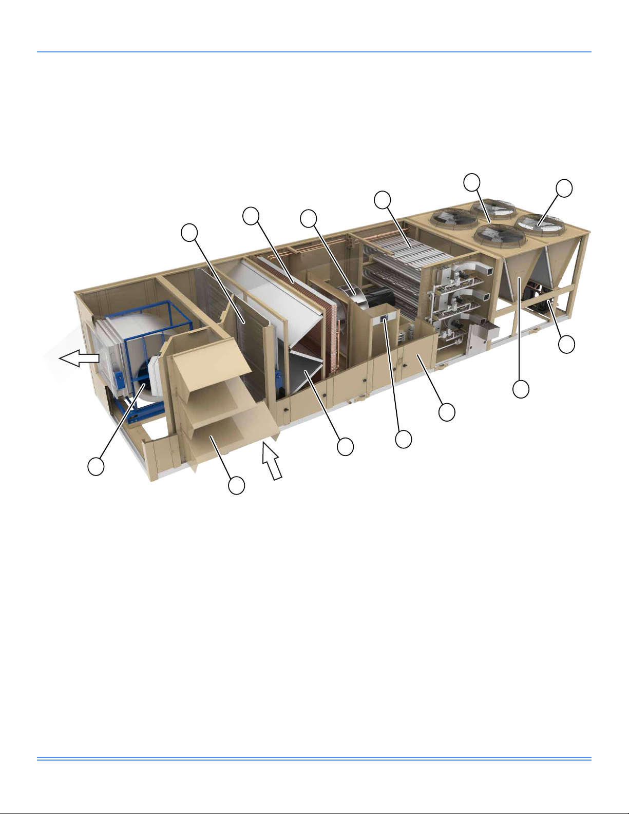
Component Location
Exhaust Air
13
5
4
2
1
3
8
9
11
10
6
7
12
1. Economizer
2. Evaporator coil
3. Direct drive plenum (DDP) supply fan
4. Modulating or staged gas heat
Figure 3: 25–50 Ton Packaged Rooftop Unit Cabinet Assembly
4
Outside Air
5. Condenser maintenance safety tie-off
6. Condenser fans
7. Scroll compressors
8. Condenser coil cleaning hatch
LD26878
9. Double wall construction
10. Unit controller
11. Filter section
12. Collapsible rain hoods
13. Exhaust/return fan
Johnson Controls
Page 5

5513350-JTG-1018
Features and Benefits
General
The 25–50 ton packaged rooftop platform is designed with
all the flexibility needed for today’s applications but with
tomorrow's requirements in mind. Realizing that efficiency
requirements are continuously pushing the envelope of
technology, the NexusPremier™ delivers today the energy
efficiency levels exceeding those mandated by the U.S.
Department of Energy for 2023. All cooling only and electric heat units have an integrated energy efficiency ratio
(IEER) in excess of 13.2. All units with gas or hydronic heat
have an IEER in excess of 13. For these particular rooftop
units, when equipped with a variable speed drive compressor, they deliver efficiency levels in excess of those suggested by the highest tier of the Consortium of Energy Ef-
ficiency (CEE) for 2019.
The NexusPremier is also designed for serviceability. With
small details—such as a maintenance safety tie-off (Item 5 in
Figure 3) on the roof of the condenser section that complies
with OSHA requirements, along with a single handle latching
mechanism for doors—the unit was designed for easy service. Options to make the unit serviceable include a convenience outlet to power lights and tools; internal lights in the air
handler section; viewports in doors of serviceable compartments to enable easier unit inspection; and extended grease
lines to simplify fan bearing lubrication for belt-driven fans.
Standard direct drive supply fan (Item 3 in Figure 3) do not
require lubricating fan bearings or changing belts. Numerous
refrigeration options are also available, including replaceable
core filter driers, liquid and suction isolation valves, as well as
high and low pressure transducers in each circuit that enable
easier sub-cooling and superheat measurements.
Besides options, there are also standard features to ensure
straightforward and safe servicing of the units, including
coil cleaning hatches (Item 8 in Figure 3) in the condenser
section to make cleaning condenser coils effortless, and
door safety latches to keep doors safe when opened in a
pressurized compartment. A discrete high and low voltage
compartment minimizes the amount of safety equipment re-
quired when only the low voltage compartment is accessed.
Selection Navigator is an online program available to assist in providing unit selections, performance reports, and
outputs to assist in design of the unit. Certain options may
require the assistance of the local sales office.
In order to facilitate its application, Selection Navigator
also provides building information modeling (BIM) files of
the specific unit selected. This aids in modeling placement
and integration of the rooftop unit into the overall building
design.
This packaged rooftop product is a sophisticated, highly
configurable rooftop unit. A controller is standard on each
unit with specific sequences of operation correlated to the
options selected. The Selection Navigator provides the
specific sequences of operation for the unit options select-
ed, eliminating confusion of the unit's capability.
Although the many options make customizing unlikely, it is
possible to have custom mechanical and sequences of operations designed into the unit from the factory for ultimate
convenience and reliability.
1. Economizer (Item 1 in Figure 3)
In order to deliver maximum efficiency, rooftop units
need an efficient economizer. The rooftop unit offers
various options for economizer control and fault de-
tection, as well as damper leakage rates and cycle
life to meet different regulatory requirements.
The amount of fresh air can also be optionally measured to ensure and record appropriate fresh air to
the conditioned space. An air blender option is also
available to deliver optimal comfort to the conditioned
space.
2. Refrigeration System (Items 2, 6, and 7 in Figure 3)
The refrigeration system is built to reliably deliver
cooling through a variety of loads. Two independent
refrigeration circuits ensure that in the unlikely event
of a compressor failure, the second circuit can still deliver cooling to the space. An interlaced tube and fin
evaporator provide maximum cooling performance
even at part loads. The microchannel condenser re-
duces the risk of refrigerant leaks and minimizes the
amount of refrigerant in the unit.
Standard fixed speed scroll compressors of different sizes deliver excellent part-load efficiency and
control, which eliminates the need for inefficient hot
gas bypass valves at low load conditions. Optional
variable speed drive scroll compressor configurations are available for stable and efficient discharge
air temperature (DAT) control regardless of the load.
For application flexibility, optional corrosion protection is available for the evaporator and condenser, as
well as intrusion protection options for the condenser.
Realizing that the refrigeration system is the heart
of the rooftop, when optionally equipped with transducers, the unit controller can display sub-cooling or
superheat. Additionally, low ambient operation is an
available option with a variable speed condenser fan.
Johnson Controls
5
Page 6

5513350-JTG-1018
Features and Benefits (Continued)
Maximized serviceability is also available with options such as replaceable core filter driers as well as
discharge, liquid, and suction line isolation valves.
The standard unit is equipped with accessible sight
glasses to verify proper refrigerant flow as well as
conveniently located condenser coil cleaning hatches to facilitate maintenance.
3. Direct Drive Plenum (DDP) Supply Fan (Item 3 in
Figure 3)
A direct drive plenum (DDP) supply fan (Figure 4)
provides outstanding reliability and efficiency, such
as eliminating the possibility of interrupting condi-
tioned air supply due to a broken belt or polluting
conditioned air with belt dust. The supply fan can
be optionally equipped with an airflow measurement
station to precisely measure the amount of air delivered to the conditioned space.
LD27636
Figure 4: DDP Supply Fan
The speed of the supply fan is controlled by a vari-
able frequency drive (VFD). A redundant VFD is
optionally available to ensure uptime in the unlikely
event of a VFD failure.
4. Heating Options (Item 4 in Figure 3)
Gas heat options are available either in staged or
modulating control. The flexibility of heater sizes
meets the specific application heating needs. Electric
heat is also available with size and staging/modulating options (Figure 5). Either hot water or steam heat
options are also available. All modulating heat options can be controlled precisely to temper the sup-
ply air, which is especially important when fresh air is
needed in cold climates.
5. Double Wall Construction (Item 9 in Figure 3)
The air handler section of the rooftop unit provides
foam injected double wall construction for maximum
unit rigidity and cleanability of the interior surfaces
for long term indoor air quality (IAQ). This construction of the walls, roof, and floor provides an insulating
value that minimizes unit sweating and contributes to
the overall unit efficiency.
LD27637
Figure 5: Electric Heat
6. Controls System (Item 10 in Figure 3)
The rooftop unit’s sophisticated options are intelligently controlled by a best-in-class controls platform
built exclusively for this application.
A 5.5-inch, 5 row × 35 character (256 × 64 dot matrix)
organic light-emitting diode (OLED) display (Figure
6) with full numerical and optimized navigational key-
pad, conveniently located in the low voltage compartment, is the nerve center. The control system can be
optionally augmented with a WiFi hotspot capability
for local or line-of-sight smart device control.
The control platform minimizes commissioning time
when connected to the Verasys™ Building Automation Systems (BAS), with self-discovery of the rooftop
unit and its points by the BAS.
6
Johnson Controls
Page 7

5513350-JTG-1018
Features and Benefits (Continued)
The unit controller has sequences of operation for
standalone applications. These sequences cover
simple applications such as single zone variable air
volume (SZVAV) control of the supply fan and compressors in accordance with ASHRAE 90.1-2016,
as well as demand control ventilation (DCV) that
ensures adequate fresh air to the building. Complex
applications are also supported, like the twinning of
multiple rooftops on a common supply and return
duct shaft for the ultimate in redundancy for critical
spaces, such as Medical Office Buildings (MOBs).
7. Blank Section (Figure 7)
Blank sections can be provided for field installed ac-
cessories or to accommodate the installation of specific factory components including an air blender, final filters, humidifier, or sound attenuator.
The rooftop unit can be equipped with a final filter
before the conditioned air is delivered from the rooftop into the supply duct. Various final filter options
are available to meet critical needs including high ef-
ficiency particulate air (HEPA) filtration. Differential
pressure measuring options can be supplied to meet
the requirements for ASHRAE 170-2017.
For cold northern climates where heat tends to dry
out the supply air, a humidifier option with a stainless
steel drain pan is also available.
In order to mitigate sound originating in the rooftop unit
from reaching the conditioned space, optional sound
attenuators in the rooftop unit can be factory-installed.
8. Exhaust/Return Fan (Item 13 in Figure 3)
The rooftop units enable installation flexibility with the
option of either exhaust or return fan to control the
building static pressure. Return ductwork with shorter runs and lower static requirements usually only
need an exhaust fan. The return fan is available to
overcome the static imposed by longer return ducts.
Refer to the Variable Air Volume for Rooftop Units
Application Guide (Form 5515844-JAD).
Figure 6: OLED Display
Figure 7: Final Filter Section
Final Filters
Blank Section
LD27638
LD26881
Optional airflow measurement is available for units
equipped with a return fan. This makes it possible
to precisely understand and log the different airflows
through the rooftop unit.
9. Hot Gas Reheat (HGRH) (Figure 9)
Occupant comfort can be a challenge during shoul-
der months when low loads and high humidity occur.
In many cases, the combined efforts of refrigeration
system compressor multistep control, an interlaced
evaporator coil, and the supply fan modulation of SZVAV control are sufficient. The rooftop unit provides
an optional modulating hot gas reheat (HGRH) coil
to further reduce the humidity level within the space.
10. Indoor Air Quality (IAQ)
To meet the critical needs of IAQ, the rooftop unit
provides a stainless steel evaporator drain pan for
longevity and to facilitate cleanability. The drain pan
can be optionally equipped with an overflow switch to
warn of improper drainage and minimize the potential
for damage to the conditioned space. Ultraviolet (UV)
light banks are also an available option that minimize
mold and bacteria growth and assists in keeping the
evaporator coil clean.
Johnson Controls
7
Page 8

5513350-JTG-1018
Features and Benefits (Continued)
11. Energy Recovery Wheel (ERW) (Figure 8)
The rooftop unit provides an option for an energy re-
covery wheel (ERW) as an integral part of the unit.
This device uses exhaust air to condition the fresh
air brought into the unit and the conditioned space,
increasing the overall rooftop efficiency. As a factoryinstalled option, the ERW ensures reliability, minimizes field labor, and simplifies long-term maintenance
of the device.
12. Airow Flexibility
Whether a rooftop unit is mounted on a roof or on a
grade, the orientation of airflow from the rooftop to
the conditioned space and vice versa is important.
The NexusPremier was specifically designed to provide discharge airflow either at the bottom, top, left,
or right.
Similarly, the return airflow is designed for maximum
flexibility vertically in either direction as well as hori-
zontally in either direction. Depending on selected
options, an end return is also possible. This airflow
flexibility minimizes installation costs and maximizes
possible locations for this flexible rooftop unit.
Energy Recovery Wheel
LD26882
Figure 8: Energy Recovery Wheel (ERW)
8
Johnson Controls
Page 9

Nomenclature
5513350-JTG-1018
25–50 Ton Model Number
12345
6789101112131415161718192021222324252627282930313233343536373839404142434445464748
G V A 1 M – 1 B 1 A A – 1 A 6 0 A – A 2 4 1 B – F 2 B B H – 5 C 1 A 1 – B K A G 1 – 0 1 0 1 C – 0 1 0 B C – 0 0 0 1
Digits 1–2: Product Brand Name
GV: Johnson Controls
Digit 3: Capacity
A: 25 Ton
B: 30 Ton
C: 40 Ton
D: 50 Ton
Digit 4: Efficiency
1: Standard Capacity, Standard Efficiency
2: Std Capacity, High Efficiency
3: High Capacity, Std Efficiency
4: Std Capacity, Std Efficiency, Low Sound
5: Std Capacity, High Efficiency, Low Sound
6: High Capacity, Std Efficiency, Low Sound
Digit 5: Heat Source
A: Cooling Only
B: Staged Gas Aluminized Burner
C: Staged Gas Stainless Steel
G: Modulating Gas Stainless Steel
K: Steam Coil
L: Hot Water Coil
M: Electric Heat
Digit 6A: Electric Heat Capacity
0: None
1: Low Heat
3: High Heat
4: Low Heat with Silicon Controlled Rectifier
(SCR)
6: High Heat with SCR
Digit 6B: Natural Gas Heat Capacity
0: None
1: 250 MBH
2: 500 MBH
3: 750 MBH
5: 1,250 MBH
Digit 6C: Hot Water or Steam
Heating Coil Option
0: None
1: Low Heat without Valves
2: Low Heat with Valves
3: High Heat without Valves
4: High Heat with Valves
Digit 7: Unit Type
A: Single Zone VAV (SZVAV) (No Duct Pressure
Transducer)
B: Variable Air Volume (VAV) (Duct Pressure
Transducer)
Digit 8: Motor Control Options
1: Supply Fan Variable Frequency Drive (VFD)
2: Supply Fan VFD with Line Reactor
3: Supply Fan VFD with Bypass (Redundant
VFD)
4: Supply Fan VFD with Line Reactor and
Bypass (Redundant VFD)
5: Supply Fan VFD and Return/Exhaust Fan VFD
6: Supply Fan VFD with Line Reactor and
Return/Exhaust Fan VFD with Line Reactor
7: Supply Fan VFD and Return/Exhaust Fan
VFD with Bypass (Redundant VFD for Supply
Fan and Bypass for Return or Exhaust Fan)
8: Supply Fan VFD with Line Reactor and
Return/Exhaust Fan VFD with Line Reactor
with Bypass (Redundant VFD for Supply Fan
and Bypass for Return or Exhaust Fan
Digit 9: Voltage
A: 208-230 V 3Ph 60 Hz, Single Point Terminal
Block
B: 208-230 V 3Ph 60 Hz, Dual Point Terminal
Block
C: 208-230 V 3Ph 60 Hz, Single Point Non Fused DISC
D: 208-230 V 3Ph 60 Hz, Single Point Terminal
Block, 65KA Short-Circuit Current Rating (SCCR)
E: 208-230 V 3Ph 60 Hz, Dual Point Terminal
Block, 65KA SCCR
F: 208-230 V 3Ph 60 Hz, Single Point Non Fused DISC, 65KA SCCR
G: 460 V 3Ph 60 Hz, Single Point Terminal Block
H: 460 V 3Ph 60 Hz, Dual Point Terminal Block
J: 460 V 3Ph 60 Hz, Single Point Non-Fused
DISC
K: 460 V 3Ph 60 Hz, Single Point Terminal
65KA SCCR
L: 460 V 3Ph 60 Hz, Dual Point Terminal Block,
65KA SCCR
M: 460 V 3Ph 60 Hz, Single Point Non-Fused
DISC, 65KA SCCR
N: 575 V 3Ph 60 Hz, Single Point Terminal Block
P: 575 VA 3Ph 60 Hz, Dual Point Terminal Block
Q: 575 V 3Ph 60 Hz, Single Point Non-Fused
DISC
R: 575 V 3Ph 60 Hz, Single Point Terminal
65KA SCCR
S: 575 V 3Ph 60 Hz, Dual Point Terminal Block,
65KA SCCR
T: 575 V 3Ph 60 Hz, Single Point Non-Fused
DISC, 65KA SCCR
Block,
Block,
Digit 10: Return Configuration
A: Bottom Return, Right Outside Air (OA), Side
Exhaust
B: Bottom Return, Right OA, Front Exhaust
C: Bottom Return, Left OA, Side Exhaust
D: Bottom Return, Left OA, Front Exhaust
E: Top Return, Right OA, Side Exhaust
F: Top Return, Right OA, Front Exhaust
G: Top Return, Left OA, Side Exhaust
H: Top Return, Left OA, Front Exhaust
J: Left Return, Right OA, Front Exhaust
K: Right Return, Left OA, Front Exhaust
L: Front Return, Left OA, Right Exhaust
M: Front Return, Right OA, Left Exhaust
N: Bottom Return, No OA, No Exhaust Air (EA)
(No Return Fan Available)
P: Top Return, No OA, No EA (No Return Fan
Available)
Q: Left Return, No OA, No EA (No Return Fan
Available)
R: Right Return, No OA, No EA (No Return Fan
Available)
S: Front Return, No OA, No EA (No Return Fan
Available)
Digit 11: Discharge Locations
1: Bottom Discharge, from Discharge Plenum
2: Bottom Discharge, Discharge through Heat
Section
3: Top Discharge, from Discharge Plenum
4: Right Discharge, from Discharge Plenum
5: Left Discharge, from Discharge Plenum
6: Left Discharge, Discharge through Heat
Section
Digit 12: Supply Configuration
A: None
B: Small Blank
C, D: Large Blank
F:
Small Blank with Humidifier and Stainless Steel
(SST) Drain Pan
H, K: Large
L: Small Blank Sound Attenuator
M, N: Large Blank Sound Attenuator
P: Small Blank Final Filter
Q, T: Large Blank with Sound Attenuator and
S, V: Large Blank with Sound Attenuator and
Digit 13: Final Filter Options
1:
MERV 15 Bag Final Filters with 2-inch MERV 8
Filters
2: MERV 14 Rigid Final Filters with 2-inch MERV
8 Filters
3: MERV 17 High Efficiency Particulate Air
(HEPA) Final Filters with 2-inch MERV 8 Filters
4: MERV 14/15 Filter Rack (No Filters)
5: HEPA Filter Rack (No Filters)
6: None
Blank with Humidifier and SST Drain
Pan
Final Filter
Humidifier and SST Drain Pan
49
Johnson Controls
9
Page 10

5513350-JTG-1018
Nomenclature (Continued)
Digit 14: Final Filter Control Options
0: None
1: Combined Pre and Post Filter Transducer
2: Separate Pre and Post Filter Transducer
3: Combined Pre and Post Filter Transducer and
Combined Magnehelic Gauge
4: Separate Pre and Post Filter Transducer and
Magnehelic Gauge
5: Combined Pre and Post Filter Magnehelic
Gauge
6:
Separate Pre and Post Filter Magnehelic Gauge
7: Combined Pre and Post Filter Transducer,
Separate Pre and Post Filter Magnehelic Gauge
Digit 15: Supply Fan
A: Direct Drive Plenum (DDP) Supply Fan with
1-inch Spring Isolation
B: DDP Supply Fan with 2-inch Spring Isolation
C: DDP Supply Fan with 2-inch Spring Isolation
and Seismic Restraint
Digit 16: Supply Fan Motor
Horsepower
A: 5 HP
B: 7.5 HP
C: 10 HP
D: 15 HP
E: 20 HP
F: 25 HP
G: 30 HP
H: 40 HP
J: 50 HP
Digit 17: Supply Fan Motor Type
2: ODP Premium Efficiency 1,800 RPM
4: TEFC Premium Efficiency 1,800 RPM
Digit 18: Supply Fan Options
0: None
1: Inlet Guard
2: Airflow Measurement Station
3: Shaft Grounding Ring
4: Inlet Guard and Airflow Measurement Station
5: Inlet Guard and Shaft Grounding Ring
6: Airflow Measurement Station and Shaft
Grounding Ring
7: Shaft Grounding Ring, Inlet Guard and Airflow
Measurement Station
Digits 19: Building Pressure Control
0: None
1: Barometric Damper
2: Exhaust with VFD and Backdraft Damper
3: Modulating Damper (On/Off Exhaust Fan Only
without VFD)
4:
Modulating Damper (Return Fan Only with VFD)
Digit 20: Return/Exhaust Fan
A: None
B: Exhaust Fan with 1-inch Spring Isolation
C: Exhaust Fan with 2-inch Spring Isolation
D: Exhaust Fan with 2-inch Spring Isolation and
Seismic Restraint
E: Return Fan with 1-inch Spring Isolation
F: Return Fan with 2-inch Spring Isolation
G: Return Fan with 2-inch Spring Isolation and
Seismic Restraint
Digit 21: Return/Exhaust Fan Motor
Horsepower
A: None
E: 3 HP
F: 5 HP
G: 7.5 HP
H: 10 HP
J: 15 HP
K: 20 HP
Digit 22: Return/Exhaust Fan Motor
Type
0: None
2: ODP Premium Efficiency 1,800 RPM
4: TEFC Premium Efficiency 1,800 RPM
Digit 23: Return/Exhaust Fan
Options
A: None
B: Shaft Grounding Ring
C: Extended Grease Lines
D:
Extended Grease Lines and Shaft Grounding
Ring
E: Belt Guards
F: Belt Guards and Shaft Grounding Ring
G: Return Fan Airflow Measurement Station
H: Return Fan Airflow Measurement Station and
Shaft Grounding Ring
J: Extended Grease Lines and Belt Guards
K: Extended Grease Lines and Belt Guards
and Shaft Grounding Ring
L: Extended Grease Lines and Return Fan
Airflow Measurement Station
M: Extended Grease Lines and Return Fan
Airflow Measurement Station and Shaft
Grounding
N: Belt Guards and Return Fan Airflow
Measurement Station
P: Belt Guards and Return Fan Airflow Measure-
ment Station and Shaft Grounding Ring
Q: Extended Grease Lines and Belt Guards and
Return Fan Airflow Measurement Station
R: Extended Grease Lines and Belt Guards and
Return Fan Airflow Measurement Station and
Shaft Grounding Ring
Digits 24: Return/Exhaust Fan Drive
A: None
B–K: RPM
Digit 25: Evaporator Options
G: Aluminum Fin Evaporator with SST Drain Pan
H: Aluminum Fin Evaporator with SST Drain Pan
with Condensate Overflow Switch
J: E-Coat Aluminum Fin Evaporator with SST
Drain Pan
K: E-Coat Aluminum Fin Evaporator with SST
Drain Pan with Condensate Overflow Switch
L: Copper Fin Evaporator with SST Drain Pan
M: Copper Fin Evaporator with SST Drain Pan
with Condensate Overflow Switch
Digit 26: Condenser Coil Options
1: None
2: With Wire Guards
3: Full Louvered Panels
4: Partial Louvered Panels
5: E-Coat Condenser without Guards
6: E-Coat Condenser with Wire Guards
7: E-Coat Condenser, Full Louvered Panels
8: E-Coat Condenser, Partial Louvered Panels
Digit 27: Draw-Thru Filter Options
A: Angled Filter Rack, No Filters
B: Angled Filter Rack, 2-Inch Throwaway Filters
C: Angled Filter Rack, 2-Inch MERV 8 Filters
D: Rigid Filter Rack, No Filters
E: Rigid Filter Rack, MERV 15 Bag Filters with
2-Inch MERV 8 Pre-Filters
F: Rigid Filter Rack, MERV 14 Rigid Filters with
2-Inch MERV 8 Pre-Filters
G: Vertical Filter Rack, No Filters
H: Vertical Filter Rack, 4-Inch MERV 8 Filters
Digit 28: Draw-Thru Filter Control
Options
0: None
1: Combined Pre and Post Filter Transducer
2: Separate Pre and Post Filter Transducer
3: Combined Pre and Post Filter Transducer and
Combined Magnehelic Gauge
4: Separate Pre and Post Filter Transducer and
Magnehelic Gauge
5: Combined Pre and Post Filter Magnehelic
Gauge
6:
Separate Pre and Post Filter Magnehelic Gauge
7: Combined Pre and Post Filter Transducer,
Separate Pre and Post Filter Magnehelic Gauge
Digit 29: Economizer Options
A: None
C: Dry Bulb Economizer, Low Leak Dampers
D: Single Enthalpy Economizer, Low Leak
Dampers
E:
Dual Enthalpy Economizer, Low Leak Dampers
F: Dry Bulb Economizer, Low Leak Dampers
with Air Measurement Station
G: Single Enthalpy Economizer, Low Leak
Dampers with Air Measurement Station
H: Dual Enthalpy Economizer, Low Leak
Dampers with Air Measurement Station
K: Dry Bulb Economizer, Ultra Low Leak Dampers
L: Single Enthalpy Economizer, Ultra Low Leak
Dampers
S: Dual Enthalpy Economizer, Ultra Low Leak
Dampers
T: Dry Bulb Economizer, Ultra Low Leak
Dampers with Air Measurement Station
U: Single Enthalpy Economizer, Ultra Low Leak
Dampers with Air Measurement Station
V: Dual Enthalpy Economizer, Ultra Low Leak
Dampers with Air Measurement Station
10
Johnson Controls
Page 11

Nomenclature (Continued)
5513350-JTG-1018
Digit 30: Energy Recovery Options
0: None
1: Low CFM Energy Recovery Wheel (ERW)
without VFD
2: Low CFM ERW with VFD
3: High CFM ERW without VFD
4: High CFM ERW with VFD
Digit 31: Refrigeration System
Piping Options
A: None
B: Suction and Discharge Valves
C: Suction, Discharge, and Liquid Valves
D: Suction, Discharge, and Liquid Valves with
Replaceable Core Filter Driers
E: Hot Gas Reheat (HGRH)
F: Suction and Discharge Valves with HGRH
G: Suction, Discharge, and Liquid Valves with
HGRH
H: Suction, Discharge, and Liquid Valves with
Replaceable Core Filter Driers with HGRH
N: E-Coat HGRH
P: Suction and Discharge Valves with E-Coat
HGRH
Q: Suction, Discharge, and Liquid Valves with
E-Coat HGRH
R: Suction, Discharge, and Liquid Valves with
Replaceable Core Filter Driers with E-Coat
HGRH
Digit 32: Lights/Detectors/Conve-
nience Options
A: None
B: Convenience Outlet
C: Convenience Outlet and Internal Lights
D: Supply Smoke Detector
E: Return Smoke Detector
F: Supply and Return Smoke Detector
G: Convenience Outlet with Supply Smoke
Detector
H: Convenience Outlet with Return Smoke
Detector
J: Convenience Outlet with Supply and Return
Smoke Detectors
K: Convenience Outlet and Internal Lights with
Supply Smoke Detector
L: Convenience Outlet and Internal Lights with
Return Smoke Detector
M: Convenience Outlet and Internal Lights with
Supply and Return Smoke Detectors
Digit 33: Controls Options
A: None
B: Low Ambient
D: Subcool and Superheat Measurement
E: Low Ambient with Subcool and Superheat
Measurement
Digit 34: Interface Options
A: BACnet® MS/TP, Modbus™, N2
B: BACnet IP
G: BACnet® MS/TP, Modbus™, N2 with Mobile
Access Portal (MAP)
H: MAP with BACnet IP
N: BACnet® MS/TP, Modbus™, N2 with Building
Automation System (BAS) Interface Board
P: BACnet IP with BAS Interface Board
U: BACnet® MS/TP, Modbus™, N2 with MAP and
BAS Interface Board
V: MAP with BACnet IP and BAS Interface Board
Digit 35: Indoor Air Quality (IAQ)
Options
0: None
1: Ultraviolet (UV) Lights
2: Carbon Dioxide (CO2) Sensors, Demand
Controlled Ventilation
3: UV Lights and CO2 Sensors
Digit 36: Gas Heat Shipped Loose
Kits
0: None
1: Gas Heat, Side Penetration
2: Gas Heat, Bottom Penetration
3: Gas Heat, High Altitude Kit Natural Gas (NG),
Side Penetration
4: Gas Heat, High Altitude Kit NG, Bottom
Penetration
5: Gas Heat, High Altitude Kit Liquid Propane
(LP), Side Penetration
6: Gas Heat, High Altitude Kit LP, Bottom
Penetration
7: Gas Heat, LP Conversion Kit, Side Penetra-
tion
8: Gas Heat, LP Conversion Kit, Bottom
Penetration
Digit 37: Security Options
0: None
1: Supply and Return Opening Burglar Bars
Digit 38: Door Options
0: None
1: Viewport
2: Single Handle with Padlock
3: Single Handle with Padlock and Viewport
Digit 39: Cabinet Shipping Options
1: Single Piece Construction
Digit 40: Curb Options
A: No Roof Curb
C: Pedestal Curb
Digit 41: Pre-Evap Options
0: None
1, 2: Blank Pre-Evap Extension, No Air Blender
3, 4: Blank Pre-Evap Extension, with Air Blender
Digit 42: Shipped Loose Options
0: None
1: Spare Belts for Return/Exhaust
Digit 43: Construction Standard
0: None
Digit 44: Supply Fan VFD Frequency
A–Z: Internal Use Only
Digit 45: Supply Fan Brake
Horsepower
A–L: Internal Use Only
Digit 46: Future 3
0: None
Digit 47: Future 4
0: None
Digit 48: Testing and Special
Quotation (SQ)
0: None
T: Record Test Report
M: Mechanical Special
1: Mechanical Special and Record Test Report
S: Software Special
3: Software Special and Record Test Report
B: Mechanical and Software Special
5: Mechanical and Software Special and Record
Test Report
Digit 49: Generation/Revision Level
1: First Generation
Johnson Controls
11
Page 12

5513350-JTG-1018
Selection Procedure Examples
GIVEN:
Required Cooling Capacity 290,000 Btuh
Required Sensible Cooling 210,000 Btuh
Required Heating 180,000 Btuh
Entering Air on Evaporator 80.0°F dry bulb (DB)/
67.0°F wet bulb (WB)
Outside Design Temperature 95.0°F
Supply Fan CFM 12,000 CFM
External Static Pressure (ESP) 3.72 iwg
Electrical Supply Voltage 460-3-60
Economizer Required
2-inch Throwaway Filters
Variable Air Volume (VAV)
Calculating Cooling/Heating Capacity
1. Assume that the required cooling capacity and required sensible capacity include the space load requirements as well as the ventilation load requirements.
2. Calculate the supply fan motor heat Btuh addition.
d. Refer to Table 6 on page 28, and find the ca-
pacity of units that meet 331.0 total cooling ca-
pacity (TMBH) and 210 sensible cooling capacity
(SMBH) at 12,000 CFM, 95.0°F ambient, 80.0°F
entering dry bulb (EDB), and 67.0°F entering wet
bulb (EWB) onto the coil. A 30-ton unit can pro-
duce 362 TMBH and 287 SMBH.
e. Calculate the leaving air temperature.
1. Calculate sensible unit capacity with motor
heat included.
• Sensible Btuh = 287 MBH - 41.0 MBH
= 246.0 MBH
2. Calculate dry bulb supply air temperature
(SAT).
• Sensible Btuh = CFM x 1.085 x ∆T
• ∆T = 246,000 Btuh / (12,000 CFM x
1.085)
• ∆T = 18.9°F
• Dry bulb SAT = entering air tempera-
ture – ∆T
a. See Select Fan Speed and Horsepower Require-
ments for Supply Fan on page 13 to determine
the horsepower (HP) of the supply fan. The example is based on a 14.91 HP requirement.
b. Calculate sensible Btuh addition as a result of the
supply fan HP.
• Supply fan sensible Btuh addition = 14.91
HP x 2,750 (constant for motor heat calculation)
• Supply fan sensible Btuh addition = 41,003
Btuh
c. Calculate the total capacity requirement.
• Total capacity = required cooling capacity
(Btuh) + supply fan motor HP (Btuh)
• Total capacity = 290,000 Btuh + 41,003 Btuh
• Total capacity = 331,003 Btuh
• Dry bulb SAT = 80.0°F – 18.9°F = 61.1 °F
3. Calculate enthalpy delta.
• Total capacity Btuh = CFM x 4.5 x ∆h
• ∆h = 363,000 Btuh / (12,000 CFM x 4.5)
• ∆h = 6.7 Btu/lb
4. Calculate wet bulb SAT.
• Leaving enthalpy = enthalpy entering –
enthalpy delta (reference psychometric
chart to convert unit wet bulb temperature to Btu/lb)
• Leaving enthalpy = 31.6 Btu/lb – 6.7
Btu/lb
• Leaving enthalpy = 24.9 Btu/lb
• Wet bulb SAT = 57.7°F
5. Leaving air temperature = 61.1°F / 57.7°F
The 30 ton unit will meet the cooling requirements.
From the nomenclature, digit 3 will be B for 30 ton
capacity. Digit 4 will be 1 for standard capacity, stan-
dard efficiency as assumed.
12
Johnson Controls
Page 13

5513350-JTG-1018
Selection Procedure Examples (Continued)
3. For gas heating capacity, reference Table 16 on page
57.
a. If the unit being selected will use gas heat, refer
to Table 16. Trace down to the output column.
b. Find the output that exceeds the 180,000 Btuh
requirement.
The 250 MBH output exceeds this requirement.
c. This option is available on the 30 ton unit.
From the nomenclature, select digit 5, option B for
staged gas, option C for staged gas with stainless
steel burner, or option G for modulating gas with
stainless steel burner.
From digit 6B, select option 1 for 250 MBH. The re-
sulting model number will show C1 for digits 5 and 6,
assuming staged gas with stainless steel burner was
selected.
4. For electric heating capacity, reference Table 17 on
page 58.
a. If the unit being selected will use electric heat, re-
fer to Table 17. Trace down to the output column.
b. Find the output that exceeds the 180,000 Btuh
requirement at the given 460-3-60 voltage.
The 60 kW output exceeds this requirement.
c. This option is available on the 30 ton unit.
From the nomenclature, select digit 5, option M for
electric heat.
From digit 6A, select either option 1 with low staged
electric heat or option 4 with low silicon controlled
rectifier (SCR) electric heat. The resulting model
number will show M4 for digits 5 and 6, assuming
low SCR electric heat was selected.
5. For steam heating capacity for a 30 ton unit, reference
Table 22 on page 60 and Table 23 on page 61.
a. Assume the unit being selected will use a 10 psig
steam supply.
b. Find the output that exceeds the 180,000 Btuh
requirement with 12,000 CFM and 10 psig.
From the nomenclature, select digit 5, option K for
steam coil.
From digit 6C, select either option 1 for low heat without valves or option 2 for low heat with valves. The
resulting model number will show K2 for digits 5 and
6, assuming the unit is field provided with valves.
6. For hot water heating capacity for a 30 ton unit, refer-
ence Table 18 on page 58 and Table 19 on page
59.
a. Assume a hot water supply temperature of
140.0°F and 20 GPM.
b. Find the output that exceeds the 180,000 Btuh
requirement with 12,000 CFM at 140.0°F and 60
GPM.
The low heat option on Table 18 exceeds this re-
quirement.
c. This option is available on the 30 ton unit.
From the nomenclature, select digit 5, option L for hot
water coil heat.
From digit 6C, select either option 1 for low heat without valves or option 2 for low heat with valves. The
resulting model number will show L2 for digits 5 and 6,
assuming the unit is field provided with valves.
Select Fan Speed and Horsepower
Requirements for Supply Fan
1. Reference Table 27 on page 64 for the 30 ton unit.
a. Make any necessary additions to the static re-
sistance for the ductwork. Refer to Table 26 on
page 62:
Ductwork Static Resistance/ESP 3.72 iwg
+ return duct static pressure (assumed) 0.50 iwg
+ economizer static resistance addition 0.33 iwg
+ bottom supply air opening resistance
addition
+ wet evaporator coil standard capacity
static resistance addition
+ gas heat (250 MBH) 0.04 iwg
+ throwaway filters 0.13 iwg
Total Static Resistance (TSP) 5.50 iwg
0.09 iwg
0.69 iwg
The low heat option on Table 22 exceeds this re-
quirement.
c. This option is available on the 30 ton unit.
Johnson Controls
b. Enter Table 27 at 12,000 CFM and 5.50 iwg TSP:
RPM = 1768
BHP = 14.91
13
Page 14
5513350-JTG-1018
Selection Procedure Examples (Continued)
2. From the nomenclature, select digit 15, option A to
opt for direct drive plenum (DDP) supply fan with
1-inch spring isolation. Select digit 16, option E for
20 HP supply fan motor. Select digit 17, option 2 for
ODP premium efciency, 1,800 RPM.
Select Fan Speed and Horsepower
Requirements of Exhaust Fan
1. Reference Table 29 on page 65 for the 30 ton unit.
In the following example, a unit is designed for exhaust air capacity of 7,000 CFM.
a. Make any necessary additions to the static resis-
tance. To find the exhaust air damper pressure
drop, refer to Table 26 on page 62:
Return duct static pressure (assumed) 0.25 iwg
+ exhaust air damper pressure drop 0.33 iwg
TSP 0.58 iwg
b. Enter at 7,000 CFM and 0.58 iwg TSP:
RPM = 634 (interpolated)
BHP = 2.72 (interpolated)
2. From the nomenclature, select digit 19, option 2 for
exhaust with variable frequency drive (VFD) and
backdraft damper; digit 20, option B for the exhaust
fan with 1-inch spring isolation; and digit 21, option
E for 3 HP exhaust fan motor. The resulting model
number will show 2BE for digits 19, 20, and 21.
Select Energy Recovery Wheel (ERW)/
Hot Gas Reheat (HGRH)/Sound Attenuator/
Humidifier
Refer to Selection Navigator or contact the local sales office
for more information on available options and accessories.
Example Model Number
The following model number is an example based on the options selected in the previous sections.
G V B 1 C – 1 B 5 G A – 1 A 6 0 A – E 2 0 2 B – E 2 A D G – 2 C 0 E 0 – D M A A 3 – 1 0 0 1 A – 0 0 0 C G – 0 0 0 1
7
5
3
4
3. Capacity 30 Ton 20. Forward Curved Exhaust Fan with 1-inch Spring Isolation
4. Standard Capacity, Standard Efciency 21. Exhaust Fan Motor, 3 HP
5. Staged Gas Stainless Steel 22. Exhaust Fan Motor Type, ODP Premium Efciency 1,800 RPM
6. 250 MBH 27. Pre-Evaporator Filter, Angled Filter Rack, 2-inch MERV 8 Filters
7. Variable Air Volume 29. Dual Enthalpy Economizer, Low Leak Dampers
8. Supply Fan with VFD and Return/Exhaust Fan with VFD
9. 460 V 3Ph 60 Hz, Single Point Terminal Block
15. Direct Drive Plenum Supply Fan with 1-inch Spring Isolation
16. Supply Fan Motor, 20 HP
17. Supply Fan Motor Type, ODP Premium Efciency 1,800 RPM 35. Ultraviolet (UV) Lights and Carbon Dioxide (CO
19. Exhaust fan with VFD and Backdraft Damper
9
6
8
15
16
17
19
20
21
22
27
31. Suction, Discharge, and Liquid Line Valves with Replaceable
Core Filter Driers
32. Convenience Outlet and Internal Lights with Supply and
Return Smoke Detectors
49. First Generation
31
29
32
35
) Sensors
2
49
14
Johnson Controls
Page 15
5513350-JTG-1018
Physical Data
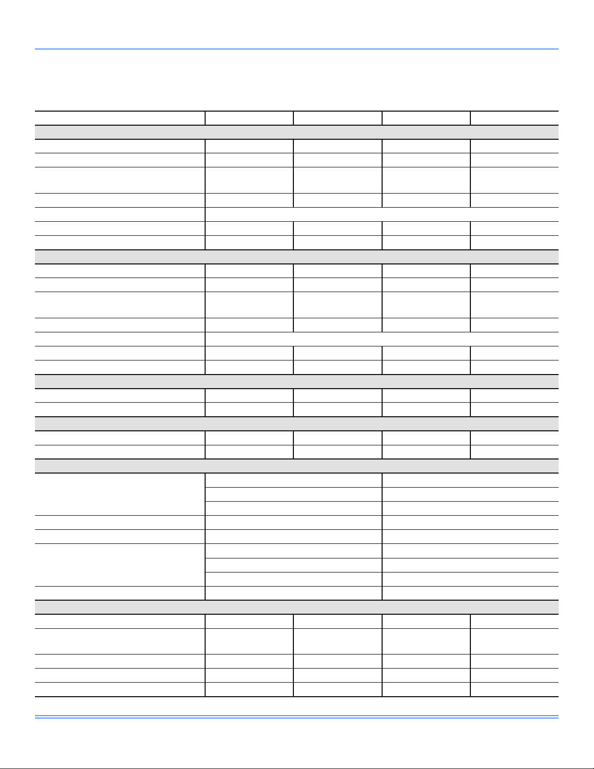
Table 1: Physical Data
Unit Size 25 Ton 30 Ton 40 Ton 50 Ton
Compressor Data - Standard Capacity, Standard Efciency
Quantity/Size (nominal HP) 1/4.5, 1/7, 1/10 1/5.5, 1/7, 1/7, 1/7.5
Type Scroll Scroll Scroll Scroll
Capacity Steps 7 11 15 15
Number of Circuits 2 2 2 2
Compressor Data - High Capacity, Standard Efciency
Quantity/Size (nominal HP) 1/5, 1/7.5, 1/10 1/5.5, 1/7, 1/7, 1/ 8.5 1/7, 1/13, 1/8.5, 1/10 1/8.5, 1/15, 1/7.5, 1/15
Type Scroll Scroll Scroll Scroll
Capacity Steps 7 11 15 13
Number of Circuits 2 2 2 2
Compressor Data - Standard Capacity, High Efciency
Quantity/Size (nominal HP) 1/5, 1/7.5, 1/13 1/7, 1/7, 1/18.5
Type
Capacity Steps 15–100% 15–100% 15–100% 15–100%
Number of Circuits 2 2 2 2
Supply Fan
Quantity of Fans/Motors 1/1 1/1 1/1 1/1
Type Direct Drive Plenum Direct Drive Plenum Direct Drive Plenum Direct Drive Plenum
Size (inches) 27 27 33 33
Motor Size Range (min to max HP) 5–25 5–25 10–50 10–50
Airow Range (min to max CFM) 5,000–12,000 5,000–12,000 8,000–20,000 8,000–20,000
Static Pressure Range (min to max iwg) 1.0–8.0 1.0–8.0 1.0–8.0 1.0–8.0
Return Fan
Quantity of Fans/Motors 1/1 1/1 1/1 1/1
Type Belt-Driven Plenum Belt-Driven Plenum Belt-Driven Plenum Belt-Driven Plenum
Size (inches) 27 27 30 30
Motor Size Range (min to max HP) 5–10 5–10 5–20 5–20
Airow Range (min to max CFM) 5,000–12,000 5,000–12,000 8,000–20,000 8,000–20,000
Static Pressure Range (min to max iwg)
Exhaust Fan
Quantity of Fans/Motors 1/1 1/1 1/1 1/1
Type
Size (inches) 18–18 18–18 25–25 25–25
Motor Size Range (min to max HP) 3–15 3–15 5–20 5–20
Airow Range (min to max CFM) 5,000–12,000 5,000–12,000 8,000–20,000 8,000–20,000
Static Pressure Range (min to max iwg) 0.5–3.0 0.5–3.0 0.5–3.0 0.5–3.0
Variable Speed
Drive Scroll
0.5–3.0 0.5–3.0 0.5–3.0 0.5–3.0
Belt-Driven Forward
Curved
Variable Speed
Drive Scroll
Belt-Driven Forward
Curved
1/5.5, 1/8.5, 1/10,
1/11.5
1/7.5, 1/7.5, 1/10,
1/13
Variable Speed
Drive Scroll
Belt-Driven Forward
Curved
1/7.5, 1/10, 1/11.5,
1/15
1/10, 1/10, 1/12,
1/17.5
Variable Speed
Drive Scroll
Belt-Driven Forward
Curved
Johnson Controls
15
Page 16
5513350-JTG-1018
Physical Data (Continued)
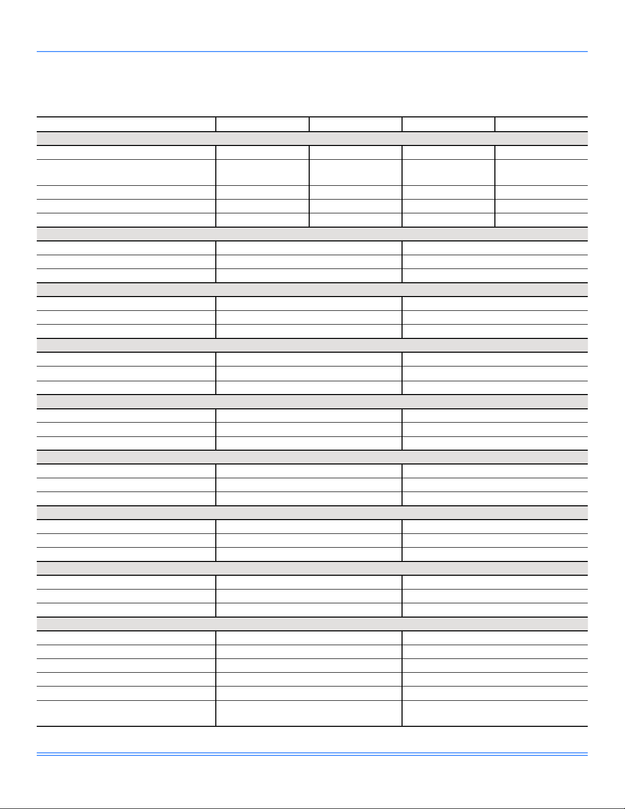
Table 1: Physical Data (Continued)
Unit Size 25 Ton 30 Ton 40 Ton 50 Ton
Condenser Fan
Quantity 2 2 4 4
Type Propeller Propeller Propeller Propeller
Size (diameter in inches) 30 30 30 30
Power (HP) 2 2 2 2
Evaporator Coil - Standard Capacity, Standard Efciency
Size (sq. ft.) 24 24 36 36
Number of Rows/Fins Per Inch 3/17 5/17 4/17 4/17
Size (tube diameter in inches) 3/8 3/8 3/8 3/8
Evaporator Coil - High Capacity, Standard Efciency
Size (sq. ft.) 24 24 36 36
Number of Rows/Fins Per Inch 4/17 6/17 4/17 6/17
Size (tube diameter in inches) 3/8 3/8 3/8 3/8
Evaporator Coil - Standard Capacity, High Efciency
Size (sq. ft.) 24 24 36 36
Number of Rows/Fins Per Inch 4/17 6/17 4/17 6/17
Size (tube diameter in inches) 3/8 3/8 3/8 3/8
Hot Gas Reheat (HGRH) Coil
Coil Type Microchannel Microchannel Microchannel Microchannel
Control Type Modulating Modulating Modulating Modulating
Size (area in sq. ft./thickness in inches) 19.5/0.8 19.5/0.8 19.5/1 19.5/1
Number of Rows/Fins Per Inch 1 / 23 1 / 23 1 / 23 1 / 23
Minimum Outside Air (OA)
Temperature for Mechanical Cooling
Low Ambient Option Minimum OA
Temperature for Mechanical Cooling
Condenser Coil - Standard Capacity, Standard Efciency
Size (sq. ft.) 61 61 98 98
Number of Rows/Fins Per Inch 1/23 1/23 1/23 1/23
Size (thickness in inches) 0.8 0.8 0.8 1
Type Microchannel Microchannel Microchannel Microchannel
Condenser Coil - High Capacity, Standard Efciency
Size (sq. ft.) 61 61 98 98
Number of Rows/Fins Per Inch 1/23 1/23 1/23 1/23
Size (thickness in inches)
Type Microchannel Microchannel Microchannel Microchannel
Condenser Coil - Standard Capacity, High Efciency
Size (sq. ft.) 61 61 98 98
Number of Rows/Fins Per Inch 1/23 1/23 1/23 1/23
Size (thickness in inches) 1 1 0.8 1
Type Microchannel Microchannel Microchannel Microchannel
0.8 0.8 0.8 1
45.0°F
-10.0°F
16
Johnson Controls
Page 17
5513350-JTG-1018
Physical Data (Continued)
Table 1: Physical Data (Continued)
Unit Size 25 Ton 30 Ton 40 Ton 50 Ton
Energy Recovery Wheel (ERW) - High CFM
Cassette Dimensions (L x W x H in inches)
Wheel Segments 6 6 8 8
Motor (V, ph, Hz)
Horsepower (HP) 1/6 1/6 1/4 1/4
Filter Type 2-inch MERV 8 Pleated
RA Filters - Size (Number) 25 x 25 (2) 25 x 25 (2) 15 x 20 (6) 15 x 20 (6)
OA Filters - Size (Number) 25 x 25 (2) 25 x 25 (2) 15 x 20 (6) 15 x 20 (6)
Energy Recovery Wheel (ERW) - Low CFM
Cassette Dimensions (L x W x H in inches)
Wheel Segments 6 6 6 6
Motor (V/ph/Hz)
Horsepower (HP) 1/6 1/6 1/6 1/6
Filter Type 2-inch MERV 8 Pleated
RA Filters - Size (Number) 25 x 25 (2) 25 x 25 (2) 15 x 20 (6) 15 x 20 (6)
OA Filters - Size (Number) 25 x 25 (2) 25 x 25 (2) 15 x 20 (6) 15 x 20 (6)
Electric Heat (208V/230V)
Size Range - Low/High (kW) 50/100 50/100 60/120 60/120
Heating Steps - Low/High 3/6 3/6 4/8 4/8
Electric Heat (460V/575V)
Size Range - Low/High (kW) 60/120 60/120 80/160 80/160
Heating Steps - Low/High 3/6 3/6 4/8 4/8
Gas Furnace
Staged Furnace Sizes
(input/output/stages)
Airow Range (min to max CFM) 5,000–12,000 8,000–20,000
Gas Heat Steady State Efciency (SSE) 81% 81%
Modulating Furnace Sizes
(input/output/turndown)
Airow Range (min to max CFM) 5,000–12,000 8,000–20,000
Hot Water Coil
Coil Tube Diameter (inches)
Material
Fins Per Inch - Low/High 13/10 13/10 13/10 13/10
Size (H x L in inches) / Rows Low 25 x 70 / 1 25 x 70 / 1 42.5 x 70 / 1 42.5 x 70 / 1
Size (H x L in inches) / Rows High 25 x 70 / 2 25 x 70 / 2 42.5 x 70 / 2 42.5 x 70 / 2
50 x 4.36 x 50 50 x 4.36 x 50 62.42 x 6.07 x 62.42 62.42 x 6.07 x 62.42
208-230/3/60,
460/3/60, 575/3/60
44 x 4.36 x 44 44 x 4.36 x 44 56.19 x 4.36 x 56.19 56.19 x 4.36 x 56.19
208-230/3/60,
460/3/60, 575/3/60
250 / 202.5 / 2 500 / 405 / 2
500 / 405 / 2 750 / 607.5 / 4
750 / 607.5 / 4 1,250 / 1012.5 / 6
250 / 202.5 / 10:1 500 / 405 / 20:1
500 / 405 / 20:1 750 / 607.5 / 30:1
750 / 607.5 / 30:1 1,250 / 1012.5 / 50:1
1/2 1/2 1/2 1/2
Copper Tube/
Aluminum Fin
208-230/3/60,
460/3/60, 575/3/60
208-230/3/60,
460/3/60, 575/3/60
Copper Tube/
Aluminum Fin
208-230/3/60,
460/3/60, 575/3/60
208-230/3/60,
460/3/60, 575/3/60
Copper Tube/
Aluminum Fin
208-230/3/60,
460/3/60, 575/3/60
208-230/3/60,
460/3/60, 575/3/60
Copper Tube/
Aluminum Fin
Johnson Controls
17
Page 18
5513350-JTG-1018
Physical Data (Continued)
Table 1: Physical Data (Continued)
Unit Size 25 Ton 30 Ton 40 Ton 50 Ton
Steam Coil
Coil Tube Diameter (inches)
Material
Fins Per Inch - Low/High 8/14 8/14 8/14 8/14
Size (H x L in inches) / Rows Low 24 x 68 / 1 24 x 68 / 1 42 x 68 / 1 42 x 68 / 1
Size (H x L in inches) / Rows High 24 x 68 / 1 24 x 68 / 1 42 x 68 / 1 42 x 68 / 1
Draw-Thru - 2-inch Throwaway Filters
Quantity
Size (L x W in inches) 24 x 24 / 16 x 20 24 x 24 / 12 x 24
Total Filter Face Area (sq. ft.) 29.33 40
Draw-Thru - 2-inch MERV 8 Filters
Quantity
Size (L x W in inches) 24 x 24 / 16 x 20 24 x 24 / 12 x 24
Total Filter Face Area (sq. ft.) 29.33 40
Draw-Thru - MERV 15 Bag Filters with 2-inch MERV 8 Pre-Filters
Quantity*
Size (L x W in inches)* 24 x 24 / 24 x 20 24 x 24 / 12 x 24
Total Filter Face Area (sq. ft.) 29.33 40
Draw-Thru - MERV 14 Rigid Filters with 2-inch MERV 8 Pre-Filters
Quantity*
Size (L x W in inches)* 24 x 24 / 24 x 20 24 x 24 / 12 x 24
Total Filter Face Area (sq. ft.) 29.33 40
Draw-Thru - Vertical 4-inch MERV 8 Filters
Quantity
Size (L x W in inches) 16 x 25 / 16 x 20 16 x 20
Total Filter Face Area (sq. ft.) 30 40
Final Filters - MERV 15 Bag Filters with 2-inch Pre-Filters
Quantity*
Size (L x W in inches)* 24 x 24 / 24 x 20 24 x 24 / 12 x 24
Total Filter Face Area (sq. ft.) 29.33 40
Final Filters - MERV 14 Rigid Filters with 2-inch Pre-Filters
Quantity*
Size (L x W in inches)* 24 x 24 / 24 x 20 24 x 24 / 12 x 24
Total Filter Face Area (sq. ft.) 29.33 40
Final Filters - MERV 17 HEPA Filters with 2-inch Pre-Filters
Quantity - Prelter
Size (L x W in inches) - Prelter 24 x 24 / 24 x 20 24 x 24 / 12 x 24
Total Filter Face Area (sq. ft.) - Prelter 29.33 40
Quantity - HEPA Filter
Size (L x W in inches) - HEPA Filter 24 x 24 12 x 24 / 12 x 17
Total Filter Face Area (sq. ft.) - HEPA
Filter
1 1 1 1
Copper Tube/
Aluminum Fin
Copper Tube/
Aluminum Fin
4 / 6 8 / 4
4 / 6 8 / 4
4 / 4 8 / 4
4 / 4 8 / 4
6 / 6 18
4 / 4 8 / 4
4 / 4 8 / 4
4 / 4 8 / 4
6 15 / 3
23.5 34.26
Copper Tube/
Aluminum Fin
Copper Tube/
Aluminum Fin
*NOTE: The quantities/sizes are the same for both the pre and post lters where noted.
18
Johnson Controls
Page 19
5513350-JTG-1018
Capacity Performance
Energy Efficiency Ratio/Integrated Energy Efficiency Ratio (EER/IEER) Ratings
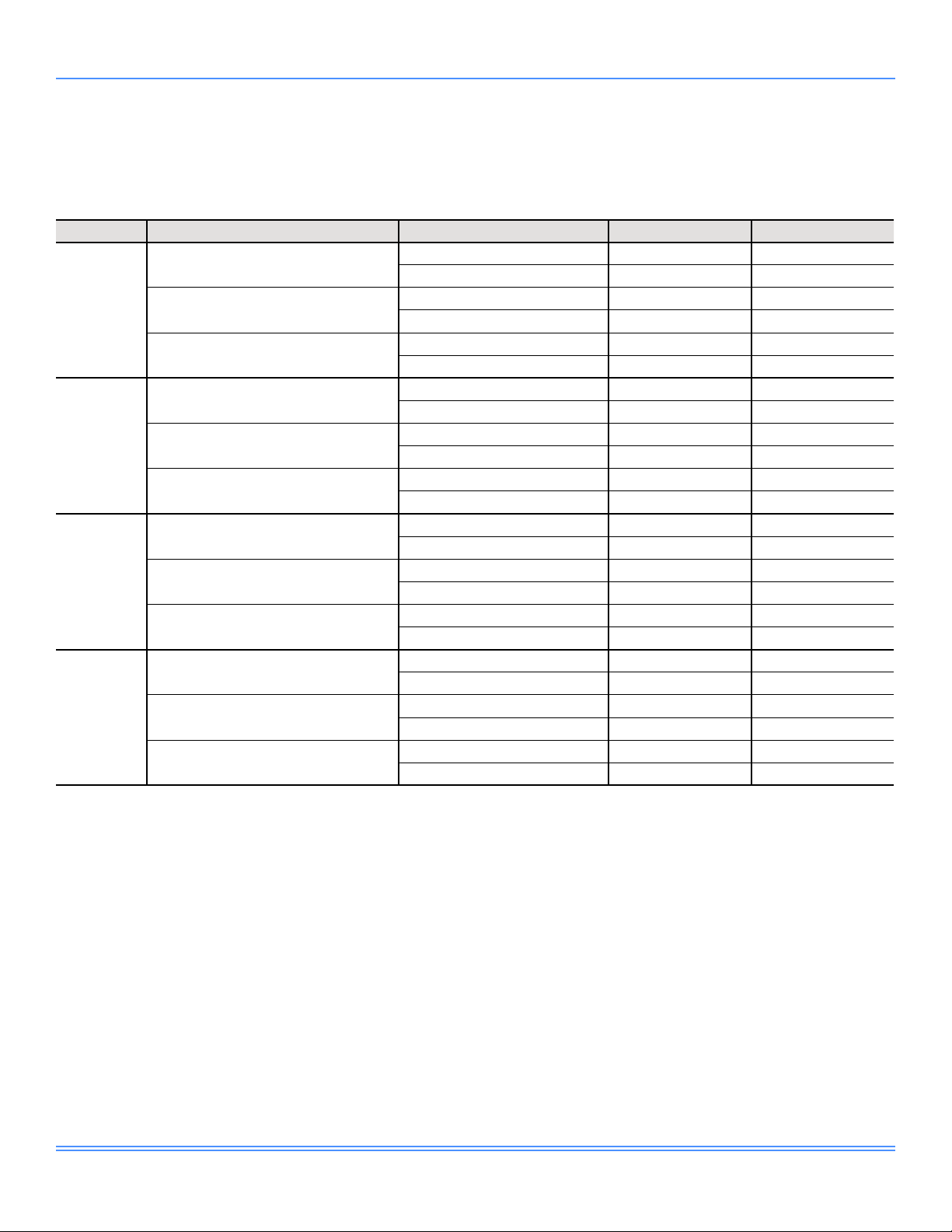
Table 2: EER/IEER Ratings
Capacity Efciency Heat Source EER IEER
Cooling Only/Electric Heat 10.8 14.9
Gas/Steam/Hot Water 10.6 14.8
Cooling Only/Electric Heat 11.4 16.7
Gas/Steam/Hot Water 11.2 16.6
Cooling Only/Electric Heat 10.8 14.9
Gas/Steam/Hot Water 10.6 14.8
Cooling Only/Electric Heat 10.5 14.3
Gas/Steam/Hot Water 10.3 14.2
Cooling Only/Electric Heat 10.9 15.2
Gas/Steam/Hot Water 10.7 15.1
Cooling Only/Electric Heat 10.5 14.3
Gas/Steam/Hot Water 10.3 14.2
Cooling Only/Electric Heat 10.9 14.6
Gas/Steam/Hot Water 10.7 14.5
Cooling Only/Electric Heat 11.1 16.1
Gas/Steam/Hot Water 10.9 16.0
Cooling Only/Electric Heat 10.7 14.6
Gas/Steam/Hot Water 10.5 14.5
Cooling Only/Electric Heat 10.8 15.0
Gas/Steam/Hot Water 10.6 14.9
Cooling Only/Electric Heat 10.9 15.9
Gas/Steam/Hot Water 10.7 15.8
Cooling Only/Electric Heat 10.5 14.8
Gas/Steam/Hot Water 10.3 14.7
25 Tons
30 Tons
40 Tons
50 Tons
Standard Capacity/Standard Efciency
Standard Capacity/High Efciency
High Capacity/Standard Efciency
Standard Capacity/Standard Efciency
Standard Capacity/High Efciency
High Capacity/Standard Efciency
Standard Capacity/Standard Efciency
Standard Capacity/High Efciency
High Capacity/Standard Efciency
Standard Capacity/Standard Efciency
Standard Capacity/High Efciency
High Capacity/Standard Efciency
Johnson Controls
19
Page 20
5513350-JTG-1018
Capacity Performance (Continued)
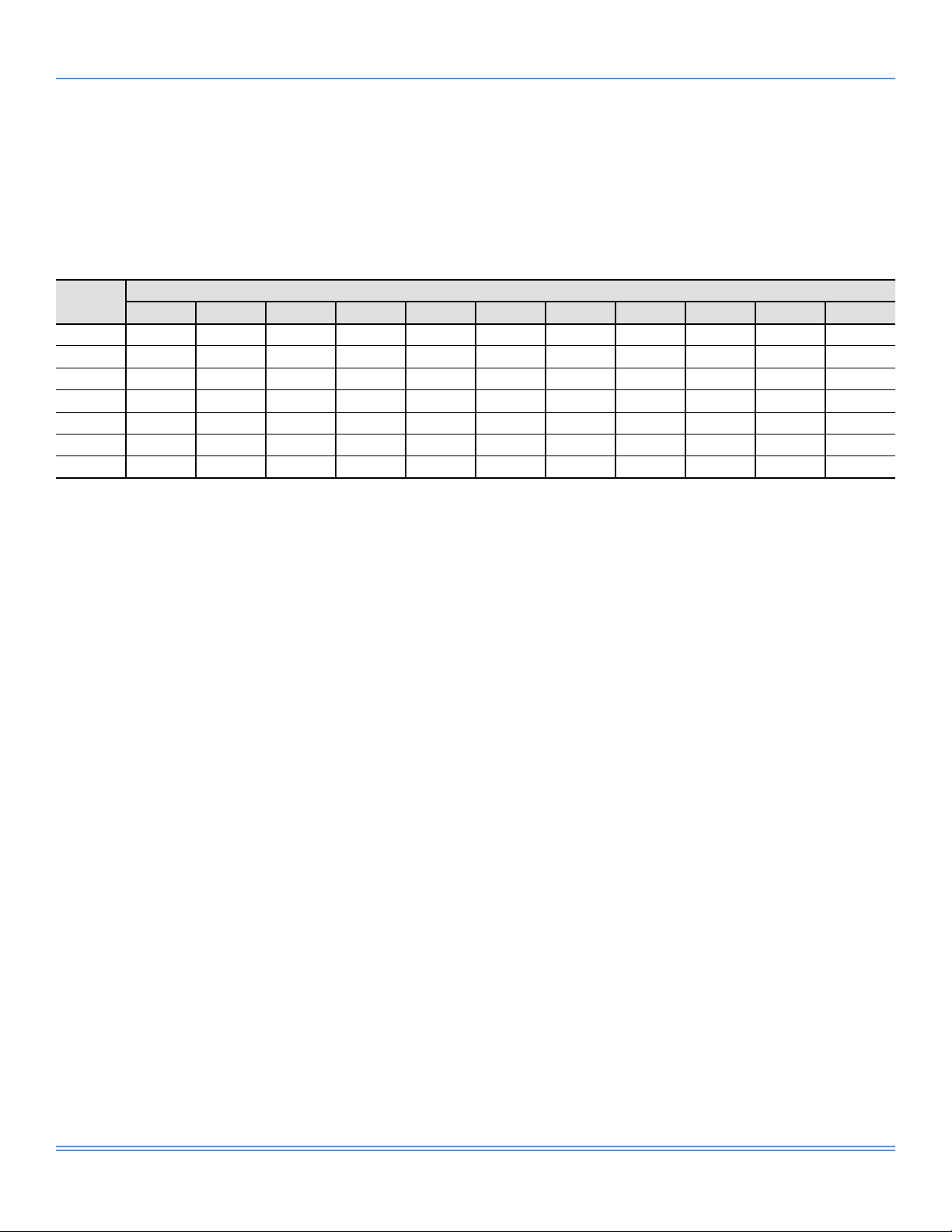
Altitude/Temperature Correction Factors
The information below should be used to assist in application of product when applied at altitudes equal to or above
1000 feet above sea level.
Table 3: Altitude/Temperature Correction Factors
Air Temp
(°F)
40 1.060 1.022 0.986 0.95 0.916 0.822 0.849 0.818 0.788 0.758 0.729
50 1.039 1.002 0.966 0.931 0.898 0.864 0.832 0.802 0.772 0.743 0.715
60 1.039 1.002 0.966 0.931 0.880 0.848 0.816 0.787 0.757 0.729 0.701
70 1.000 0.964 0.930 0.896 0.864 0.832 0.801 0.772 0.743 0.715 0.688
80 0.982 0.947 0.913 0.88 0.848 0.817 0.787 0.758 0.73 0.702 0.676
90 0.964 0.929 0.897 0.864 0.833 0.802 0.772 0.744 0.716 0.689 0.663
100 0.946 0.912 0.880 0.848 0.817 0.787 0.758 0.730 0.703 0.676 0.651
0* 1,000 2,000 3,000 4,000 5,000 6,000 7,000 8,000 9,000 10,000
Altitude (feet)
*NOTE: Correction factors at sea level to calculate for actual tempera-
ture conditions.
The examples below will assist in determining the airflow
performance of NexusPremier™ at specific altitudes.
Example 1: What are the corrected cubic feet per minute
(CFM), static pressure, and brake horse power (BHP) at
an elevation of 5,000 feet if the airflow performance data is
6,000 CFM, 1.4 inches of water gauge (iwg), and 2.0 BHP?
Solution: At an elevation of 5,000 feet, the supply fan still
delivers 6,000 CFM if the revolutions per minute (RPM) is
unchanged. However, the altitude correction must be used
to determine the static pressure and BHP. Since no tem-
perature data is given, we assume an air temperature of
70.0°F. Table 3 shows the correction factor to be 0.832.
Corrected static pressure = 1.4 x 0.832 = 1.16 iwg
Corrected BHP = 2.0 x 0.832 = 1.66
Example 2: A system, located at 5,000 feet of elevation is
to deliver 6,000 CFM at a static pressure of 1.4 iwg. Use
the unit blower tables to select the RPM, blower speed, and
the BHP requirement.
Solution: As in the example above, no temperature information is given, so 70.0°F is assumed.
Enter Table 27 on page 64 at 6,000 CFM and static pres-
sure of 1.68 iwg. The RPM listed is the same RPM needed
at 5,000 feet.
Using interpolation, the corresponding BHP listed in the
table is 2.25. This value must be corrected for elevation.
BHP at 5,000 feet = 2.25 x 0.832 = 1.87
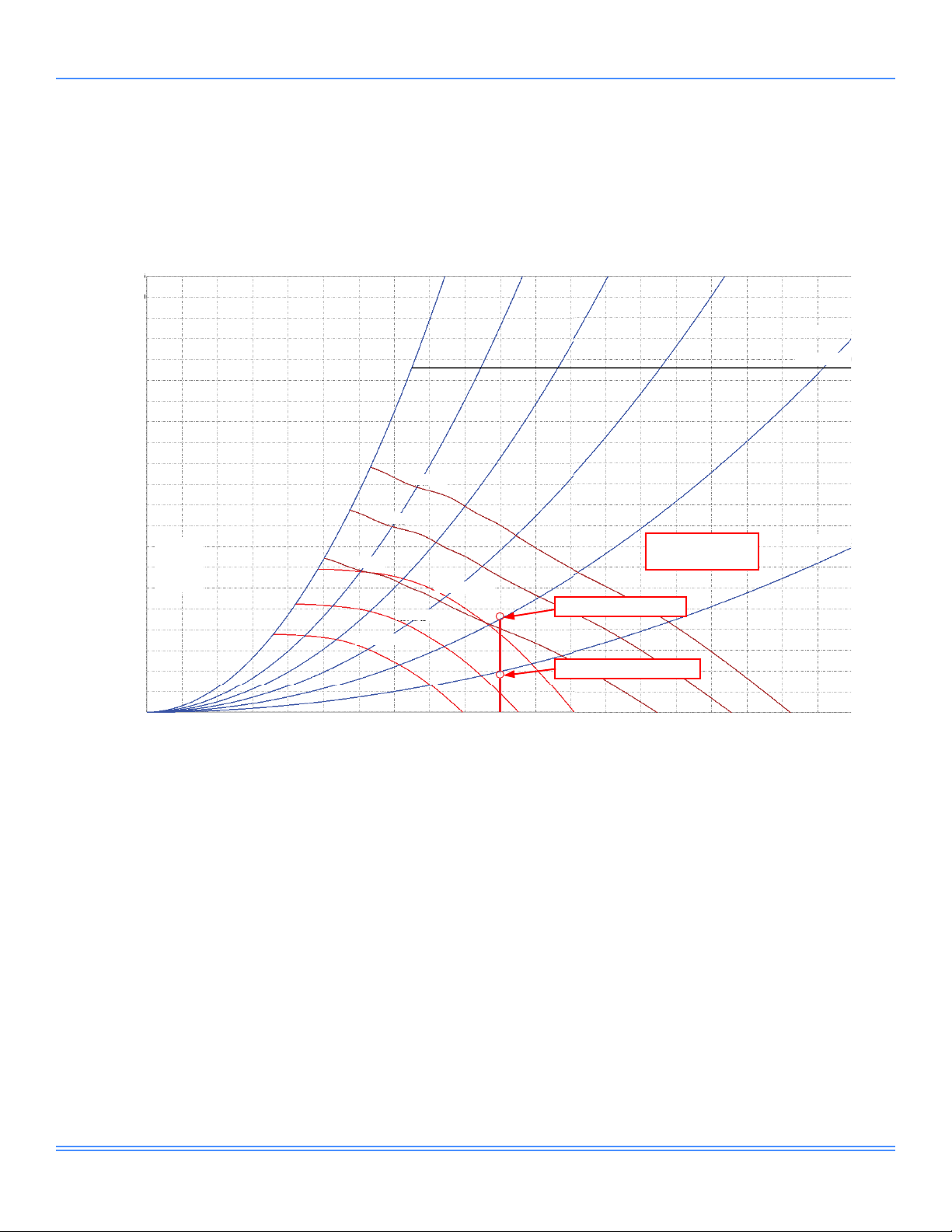
Example 3: Plot fan performance using Table 26 on page
62.
Plot the fan performance at cooling sea level (0 feet) elevation. Design conditions are a 25-ton unit producing 10,000
CFM at 1.5 external static pressure (ESP) with additional
static losses for a wet evaporator coil, bottom return air,
bottom supply air, outside air, and angled filter rack with
2-inch MERV 8 filters.
Wet evaporator coil standard capacity
additional static loss = 0.41 iwg
Bottom return air additional static loss = 0.05 iwg
Bottom supply air additional static loss = 0.06 iwg
Outside air additional static loss = 0.30 iwg
Air filter additional static loss = 0.11 iwg
The 1.4 iwg static pressure given is at an elevation of 5,000
feet. The first step is to convert this static pressure to equivalent sea level conditions.
Sea level static pressure = 1.4 iwg / 0.832 = 1.68 iwg
20
Add the ESP and all additional losses (internal static loss):
ESP loss = 1.5 iwg
Total internal static loss = 0.93 iwg
Total system static = 2.43 iwg
Johnson Controls
Page 21
Capacity Performance (Continued)
5513350-JTG-1018
10.5
10.0
9.5
9.0
8.5
8.0
7.5
7.0
6.5
6.0
5.5
5.0
4.5
Do Not
4.0
Select in
3.5
Static Pressure (iwg)
3.0
2.5
2.0
1.5
1.0
0.5
0.0
This
Region
1.0 2.0 3.0 4.0 5.0 6.0 7.0 8.0 10.09.0
0.0
10 HP
7.5 HP
5 HP
1266 RPM
1101 RPM
936 RPM
Flow Rate (CFM x 1,000)
70% W.O.60% W.O.50% W.O.40% W.O.
Total System Static
= 2.43 inches
1.5-inch external static
0.93-inch internal static
12.0 13.0 14.0 15.0 16.0 17.0 18.0 19.0 20.0
11.0
80% W.O.
Max TSP
90% W.O.
LD26887
Figure 9: 25-Ton Unit Fan Performance
Johnson Controls
21
Page 22
5513350-JTG-1018
Capacity Performance (Continued)
Cooling Performance Data
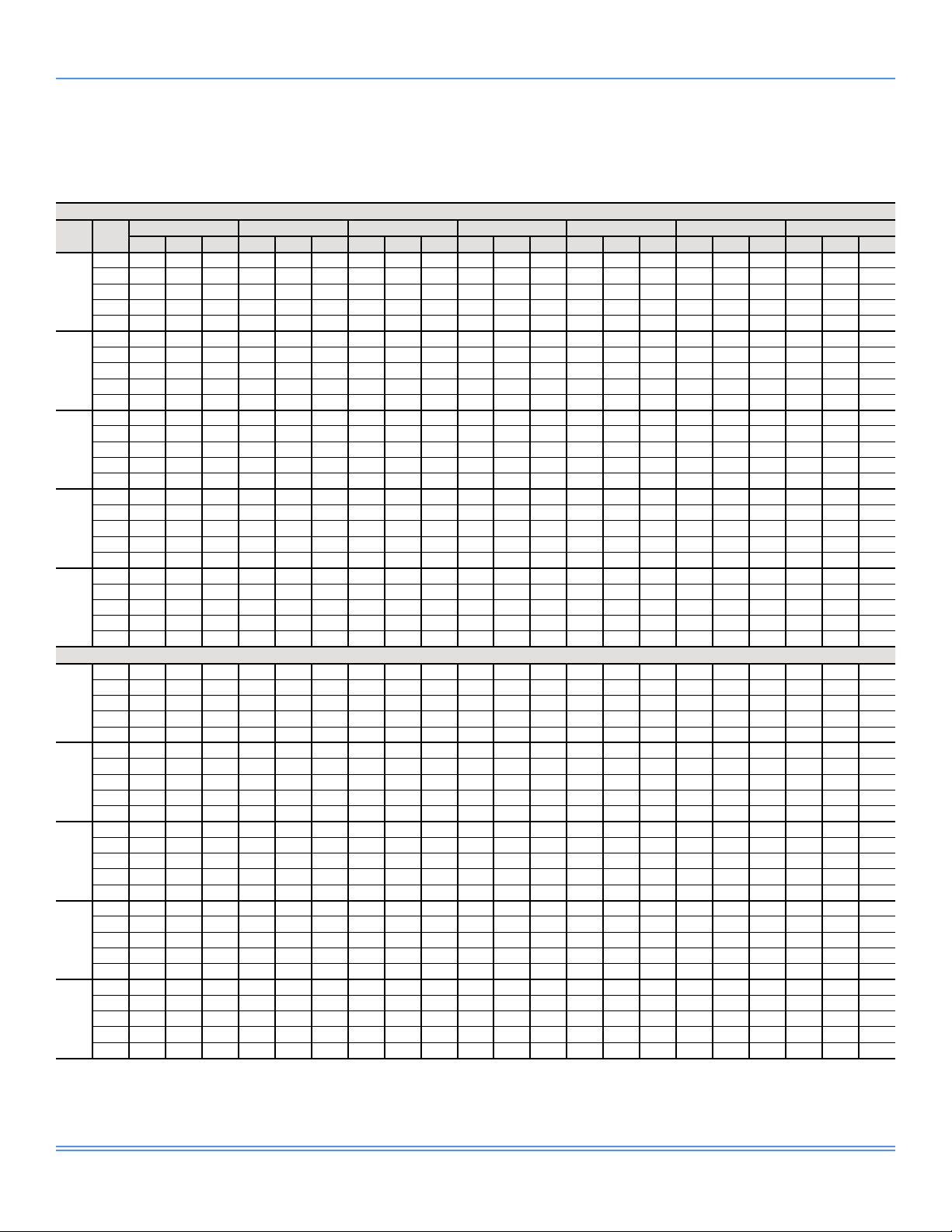
Table 4: Cooling Performance Data - 25 Ton Standard Efficiency
75°F Ambient Air Temperature
EWB
CFM
(°F)
77 342 206 20 342 179 20 341 152 20 341 125 20 - - - - - - - - 72 313 234 20 314 207 20 313 181 20 313 154 20 313 127 20 - - - - - 67 288 261 19 287 235 19 287 208 19 286 181 19 285 153 19 284 126 19 - - -
5,000
62 275 275 19 262 258 19 259 231 19 259 204 19 258 177 19 257 150 19 256 122 19
57 274 274 19 260 260 19 - - - - - 77 365 242 20 363 205 20 363 169 20 362 132 20 - - - - - - - - 72 336 279 20 336 243 20 334 207 20 334 171 20 333 134 20 - - - - - 67 315 314 20 310 280 19 308 244 19 307 208 19 305 171 19 304 134 19 - - -
6,750
62 314 314 20 298 298 19 283 277 19 279 241 19 278 205 19 276 168 19 275 131 19
57 314 314 20 297 297 19 280 280 19 264 264 19 253 238 19 251 201 19 249 165 19
77 379 276 20 377 230 20 377 185 20 375 138 20 - - - - - - - - 72 353 322 20 350 278 20 348 232 20 347 187 20 346 141 20 - - - - - 67 343 343 20 328 322 20 322 278 20 319 232 20 318 187 20 316 140 20 - - -
8,500
62 343 343 20 326 326 20 307 307 19 294 276 19 290 230 19 289 184 19 287 138 19
57 342 342 20 325 325 20 306 306 19 288 288 19 270 269 19 263 227 19 261 182 19
77 390 309 21 387 254 21 386 200 21 384 144 20 - - - - - - - - 72 368 362 20 361 311 20 357 257 20 356 202 20 354
67 366 366 20 347 347 20 333 312 20 328 257 20 327 202 20 324 146 20 - - 62 365 365 20 347 347 20 327 327 20 307 306 20 299 255 19 297 200 19 295 145 19
10,250
57 365 365 20 346 346 20 326 326 20 306 306 20 287 287 19 272 252 19 269 198 19
77 398 342 21 394 279 21 392 215 21 390 150 21 - - - - - - - - 72 385 385 21 370 343 20 364 281 20 363 217 20 361 153 20 - - - - - 67 384 384 20 364 364 20 344 340 20 335 281 20 333 217
62 383 383 20 363 363 20 343 343 20 321 321 20 307 278 20 303 215 19 301 150 19
12,000
57 383 383 20 363 363 20 342 342 20 320 320 20 299 299 19 281 274 19 275 213 19
77 330 201 22 329 174 22 329 147 22 329 120 22 - - - - - - - - 72 301 227 21 300 200 21 299 173 21 298 145 21 298 118 21 - - - - - 67 274 252 21 272 225 21 272 198 21 271 171 21 270 144 21 269 11 6 21 - - -
5,000
62 262 262 21 249 247 21 245 221 21 244 194 21 243 167
57 261 261 21 247 247 21 - - - - - - - - - - - - - - 77 351 237 22 350 200 22 349 164 22 347 127 22 - - - - - - - - 72 322 272 22 320 236 22 318 199 22 318 162 22 316 125 22 - - - - - 67 302 302 21 294 270 21 291 234 21 290 197 21 289 161 21 287 124 21 - - -
6,750
62 300 300 21 283 283 21 268 265 21 263 230 21 262 194 21 260 157 21 259 121 21
57 299 299 21 282 282 21 266 266 21 250 250 21 237 226 21
77 364 271 22 363 225 22 362 179 22 359 132 22 - - - - - - - - 72 338 315 22 333 270 22 331 223 22 330 178 22 327 131 22 - - - - - 67 330 330 22 312 310 22 305 268 22 302 222 21 301 177 21 298 130 21 - - -
8,500
62 329 329 22 310 310 22 292 292 21 277 265 21 273 219 21 271 174 21 269 127 21
57 328 328 22 309 309 22 291 291 21 272 272 21 255 255 21 246 215 21 244 170 21
77 373 304 22 371 249 22 369 194 22 367 138 22 - - - - - - - - 72 353 352 22 343 303 22 339 248 22 338 193 22 335 137 22 - - - - - 67 352 352 22 332 332 22 316 301 22 310 247 22 309 192 22 306 137 22 - - 62 351 351 22 331 331 22 3 11 311 22 291 291 21 281 244 21 279 189 21 277 134 21
10,250
57 351 351 22 330 330 22 310 310 22 290 290 21 270 270 21 255 240 21 252 186 21
77 382 336 23 378 273 22 375 208 22 372 143 22 - - - - - - - - 72 370 370 22 352 333 22 346 272 22 343 207 22 340 142 22 67 370 370 22 348 348 22 326 326 22 317 271 22 314 207 22 3 11 142 22 - - 62 369 369 22 347 347 22 325 325 22 304 304 22 289 267 21 285 204 21 282 140 21
12,000
57 369 369 22 346 346 22 324 324 22 303 303 22 283 283 21 263 261 21 257 201 21
NOTES:
Rated performance is at sea level. Cooling capacities are gross cooling capacities.
CFM = airow EWB = entering wet bulb air EDB = entering dry bulb air TMBH = total cooling capacity (MBH)
SMBH = sensible cooling capacity (MBH) kW = total input
95°F EDB 90°F EDB 85°F EDB 80°F EDB 75°F EDB 70°F EDB 65°F EDB
TMBH SMBH kW TMBH SMBH kW TMBH SMBH kW TMBH SMBH kW TMBH SMBH kW TMBH SMBH kW TMBH SMBH kW
- - - - - - - - -
147 20 - - - - - -
20 330 152 20 - - -
85°F Ambient Air Temperature
21 242 139 21 241 112 21
235 190 21 233 153 21
- - - - -
22
Johnson Controls
Page 23
Capacity Performance (Continued)
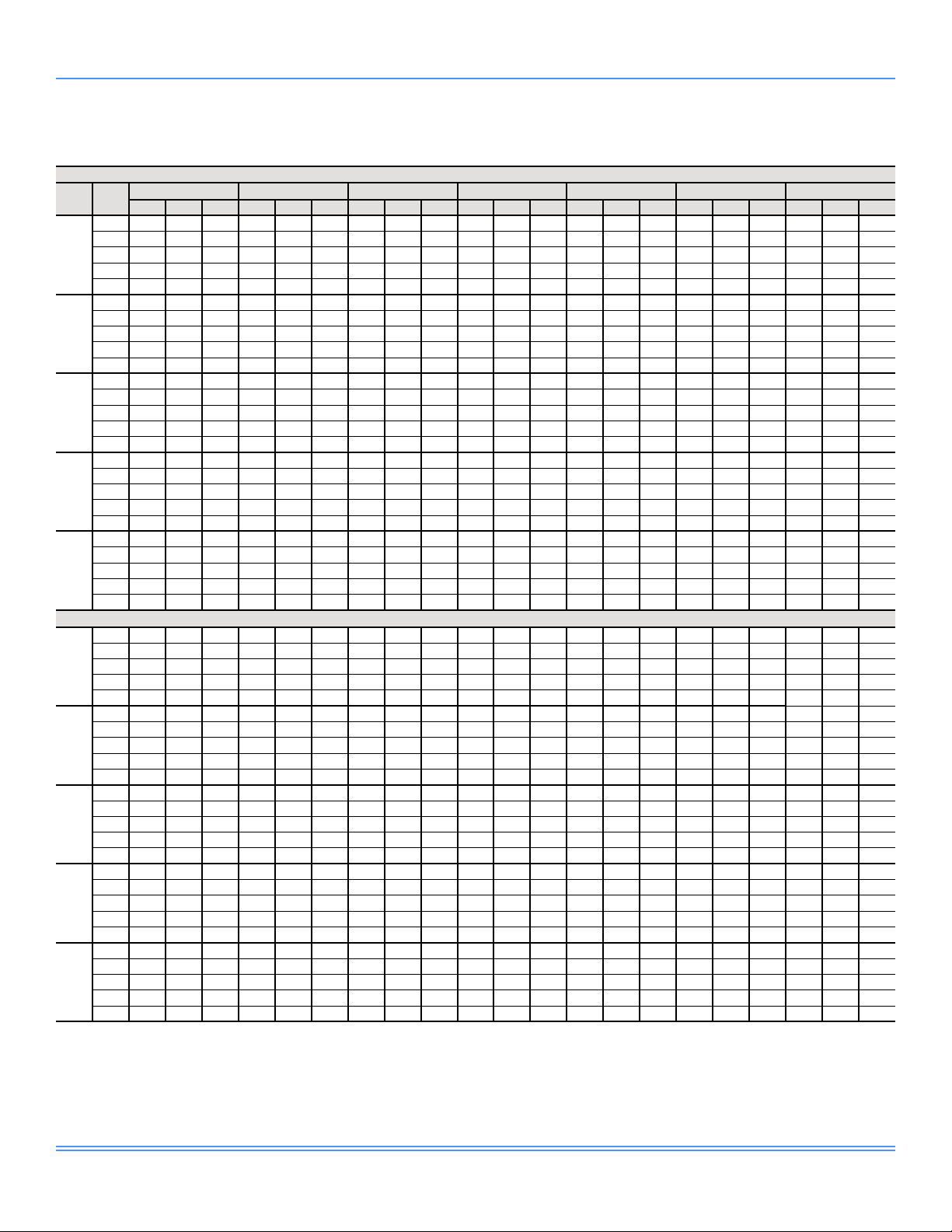
Table 4: Cooling Performance Data - 25 Ton Standard Efciency (Continued)
95°F Ambient Air Temperature
EWB
CFM
(°F)
77 312 192 24 311 164 24 310 137 24 309 109 24 - - - - - - - - 72 284 217 24 283 190 24 282 163 24 281 136 24 281 108 24 - - - - - 67 260 244 23 258 217 23 258 190 23 257 163 23 256 136 23 256 109 23 - - -
5,000
62 250 250 23 237 237 23 231 212 23 230 185 23 229 158 23 228 131 23 228 104 23
57 247 247 23 233 233 23 219 219 23 - - 77 331 226 24 329 190 24 328 153 24 326 115 24 - - - - - - - - 72 304 262 24 302 226 24 300 189 24 299 152 24 297 115 24 - - - - - 67 289 289 24 279 262 24 276 226 24 274 189 23 274 153 23 272 11 6 23 - - -
6,750
62 286 286 24 270 270 23 254 254 23 248 221 23 246 184 23 245 148 23 243 111 23
57 284 284 24 267 267 23 251 251 23 235 235 23 221 214 23 218 178 23 216 142 23
77 342 260 24 341 214 24 339 168 24 337 121 24 - - - - - - - - 72 319 304 24 314 259 24 3 11 213 24 310 168 24 308 121 24 - - - - - 67 316 316 24 298 298 24 289 260 24 285 214 24 284 169 24 282 122 24 - - -
8,500
62 313 313 24 295 295 24 277 277 24 262 255 23 256 210 23 255 164 23 253 118 23
57 311 311 24 292 292 24 274 274 24 256 256 23 239 239 23 228 204 23 227 158 23
77 351 292 25 349 238 25 346 182 24 343 126 24 - - - - - - - - 72 336 336 24 323 292 24 319 238 24 317 182 24 315
67 336 336 24 317 317 24 299 291 24 293 239 24 291 184 24 289 128 24 - - 62 334 334 24 314 314 24 295 295 24 275 275 24 265 234 23 262 180 23 260 124 23
10,250
57 332 332 24 312 312 24 292 292 24 272 272 24 253 253 23 237 227 23 233 174 23
77 359 324 25 354 262 25 351 196 25 348 131 25 - - - - - - - - 72 351 351 25 332 322 24 325 261 24 322 197 24 319 132 24 - - - - - 67 352 352 25 331 331 24 3 11 311 24 300 262 24 296 198
62 350 350 25 329 329 24 308 308 24 288 288 24 272 257 24 267 194 23 264 130 23
12,000
57 348 348 25 327 327 24 306 306 24 285 285 24 265 265 23 246 246 23 238 189 23
77 292 180 26 290 153 26 290 125 26 288 98 26 - - - - - - - - 72 264 205 26 263 178 26 262 151 26 261 123 26 260 96 26 - - - - - 67 242 231 26 239 204 26 238 177 26 237 150 26 237 123 26 236 95 26 - - -
5,000
62 234 234 26 220 220 26 212 198 26 211 172 26 210 144
57 233 233 26 219 219 26 205 205 25 191 191 25 186 166 25 185 139 25 - - 77 308 214 27 307 178 27 306 141 27 304 104 27 - - - - - - - - 72 282 249 26 280 213 26 278 176 26 277 139 26 275 102 26 - - - - - 67 271 271 26 259 248 26 255 213 26 253 176 26 252 140 26 250 103 26 - - -
6,750
62 269 269 26 252 252 26 236 236 26 228 207 26 225 171 26 224 134 26 222 97 26
57 267 267 26 251 251 26 235 235 26 219 219 26 204 202 25
77 319 248 27 317 202 27 315 155 27 313 109 27 - - - - - - - - 72 298 290 27 291 246 27 289 201 27 287 154 26 284 108 26 - - - - - 67 297 297 27 279 279 26 267 246 26 263 201 26 262 155 26 260 109 26 - - -
8,500
62 294 294 27 276 276 26 258 258 26 241 239 26 235 196 26 233 150 26 231 104 26
57 293 293 27 275 275 26 257 257 26 239 239 26 221 221 26 210 191 26 207 146 26
77 328 280 27 324 226 27 322 170 27 319 114 27 - - - - - - - - 72 315 315 27 300 278 27 296 225 27 293 169 27 290 113 27 - - - - - 67 316 316 27 296 296 27 278 275 26 271 225 26 268 170 26 265 11 4 26 - - 62 314 314 27 294 294 27 274 274 26 255 255 26 243 220 26 239 165 26 237 110 26
10,250
57 313 313 27 292 292 27 273 273 26 254 254 26 235 235 26 218 214 26 213 161 26
77 336 312 27 330 250 27 326 185 27 323 119 27 - - - - - - - - 72 330 330 27 310 306 27 301 248 27 298 184 27 295 119 27 67 331 331 27 311 311 27 290 290 27 277 248 26 272 185 26 270 120 26 - - 62 329 329 27 308 308 27 288 288 27 268 268 26 250 242 26 244 180 26 241 115 26
12,000
57 328 328 27 307 307 27 286 286 27 266 266 26 247 247 26 228 228 26 218 176 26
95°F EDB 90°F EDB 85°F EDB 80°F EDB 75°F EDB 70°F EDB 65°F EDB
TMBH SMBH kW TMBH SMBH kW TMBH SMBH kW TMBH SMBH kW TMBH SMBH kW TMBH SMBH kW TMBH SMBH kW
- - - - - - - - -
105°F Ambient Air Temperature
5513350-JTG-1018
127 24 - - - - - -
24 294 134 24 - - -
26 209 117 25 208 90 25
199 166 25 198 130 25
- - - - -
NOTES:
Rated performance is at sea level. Cooling capacities are gross cooling capacities.
CFM = airow EWB = entering wet bulb air EDB = entering dry bulb air TMBH = total cooling capacity (MBH)
SMBH = sensible cooling capacity (MBH) kW = total input
Johnson Controls
23
Page 24

5513350-JTG-1018
Capacity Performance (Continued)
Table 4: Cooling Performance Data - 25 Ton Standard Efciency (Continued)
115°F Ambient Air Temperature
EWB
CFM
(°F)
77 269 168 29 268 141 29 267 11 3 29 266 85 29 - - - - - - - - 72 243 192 29 242 165 29 240 138 29 239 110 29 238 82 29 - - - - - 67 220 215 29 217 189 29 215 162 29 214 134 29 213 107 29 212 79 29 - - -
5,000
62 217 217 29 204 204 29 193 185 28 191 158 28 190 131 28 189 103 28 187 76 28
57 217 217 29 203 203 29 189 189 28 176 176 28
77 284 202 30 283 165 30 281 128 30 279 91 30 - - - - - - - - 72 260 236 29 256 199 29 255 163 29 253 126 29 251 89 29 - - - - - 67 251 251 29 236 232 29 230 197 29 228 160 29 227 123 29 225 86 29 - - -
6,750
62 250 250 29 234 234 29 218 218 29 207 193 29 203 157 29 202 120 29 200 83 29
57 249 249 29 233 233 29 217 217 29 202 202 29 186 186 28 180 153 28 179 117 28
77 294 235 30 292 190 30 290 143 30 287 96 30 - - - - - - - - 72 275 274 30 267 233 29 264 187 29 262 141 29 259 94 29 - - - - - 67 275 275 30 256 256 29 242 229 29 238 185 29 235 138 29 233 92 29 - - -
8,500
62 274 274 30 256 256 29 238 238 29 220 220 29 213 182 29 210 136 29 208 90 29
57 273 273 30 255 255 29 237 237 29 220 220 29 203 203 29 190 178 28 187 133 28
77 303 268 30 299 213 30 296 158 30 293 102 30 - - - - - - - - 72 293 293 30 276 264 30 271 2 11 30 268 156 29 265
67 292 292 30 273 273 30 254 254 29 244 209 29 241 153 29 238 98 29 - - 62 292 292 30 272 272 30 253 253 29 235 235 29 220 205 29 216 151 29 213 95 29
10,250
57 291 291 30 272 272 30 253 253 29 234 234 29 216 216 29 199 198 29 192 148 29
77 311 298 30 304 237 30 300 172 30 296 107 30 - - - - - - - - 72 307 307 30 287 287 30 276 235 30 272 170 30 268 105 29 - - - - - 67 307 307 30 286 286 30 266 266 29 250 231 29 245 168
62 306 306 30 286 286 30 266 266 29 246 246 29 227 225 29 220 166 29 217 101 29
12,000
57 306 306 30 285 285 30 265 265 29 246 246 29 227 227 29 208 208 29 196 163 29
95°F EDB 90°F EDB 85°F EDB 80°F EDB 75°F EDB 70°F EDB 65°F EDB
TMBH SMBH kW TMBH SMBH kW TMBH SMBH kW TMBH SMBH kW TMBH SMBH kW TMBH SMBH kW TMBH SMBH kW
168 154 28 167 127 28 166 99 28
100 29 - - - - - -
29 242 103 29 - - -
NOTES:
Rated performance is at sea level. Cooling capacities are gross cooling capacities.
CFM = airow EWB = entering wet bulb air EDB = entering dry bulb air TMBH = total cooling capacity (MBH)
SMBH = sensible cooling capacity (MBH) kW = total input
24
Johnson Controls
Page 25

Capacity Performance (Continued)
Table 5: Cooling Performance Data - 25 Ton High Efficiency
75°F Ambient Air Temperature
EWB
CFM
(°F)
77 351 211 18 351 184 18 350 157 18 350 129 18 - - - - - - - - 72 321 239 18 321 212 18 321 185 18 320 158 18 320 131 18 - - - - - 67 294 266 18 293 239 18 292 212 18 292 184 18 290 156 18 290 129 18 - - -
5,000
62 279 279 18 266 262 18 263 235 18 262 208 18 262 180 18 261 153 18 260 125 18
57 279 279 18 264 264 18 - - - - - 77 375 248 19 374 211 19 374 174 19 373 137 19 - - - - - - - - 72 345 286 18 344 249 18 343 213 18 343 176 18 342 139 18 - - - - - 67 322 321 18 317 286 18 315 249 18 314 212 18 312 175 18 3 11 138 18 - - -
6,750
62 321 321 18 304 304 18 288 282 18 284 246 18 283 209 18 282 172 18 281 134 18
57 321 321 18 303 303 18 285 285 18 268 268 18 257 242 18 255 205 18 253 168 18
77 391 284 19 389 237 19 389 191 19 387 144 19 - - - - - - - - 72 363 331 18 360 285 18 358 239 18 358 193 18 356 146 18 - - - - - 67 352 352 18 336 330 18 330 285 18 327 238 18 326 192 18 324 145 18 - - -
8,500
62 352 352 18 333 333 18 314 314 18 300 282 18 296 235 18 295 189 18 293 142 18
57 351 351 18 333 333 18 313 313 18 294 294 18 275 275 18 268 232 18 266 185 18
77 402 319 19 400 263 19 398 206 19 396 150 19 - - - - - - - - 72 379 373 19 371 320 19 368 264 19 367 208 19 365
67 376 376 19 357 357 18 342 320 18 337 264 18 335 208 18 333 151 18 - - 62 376 376 19 356 356 18 335 335 18 314 313 18 306 261 18 304 205 18 302 148 18
10,250
57 375 375 19 356 356 18 335 335 18 314 314 18 293 293 18 277 258 18 275 202 18
77 411 353 19 408 288 19 405 222 19 402 156 19 - - - - - - - - 72 397 397 19 381 354 19 376 289 19 374 224 19 371 158 19 - - - - - 67 396 396 19 375 375 19 353 350 18 345 289 18 342 223
62 395 395 19 374 374 19 352 352 18 329 329 18 314 286 18 310 221 18 308 155 18
12,000
57 395 395 19 374 374 19 352 352 18 329 329 18 307 307 18 287 282 18 281 218 18
77 337 206 20 337 179 20 337 151 20 336 124 20 - - - - - - - - 72 307 232 20 306 204 20 305 177 20 304 149 20 304 121 20 - - - - - 67 277 255 20 276 228 20 275 200 20 274 173 20 273 145 20 273 11 7 20 - - -
5,000
62 266 266 20 252 250 20 248 224 20 247 196 20 246 169
57 265 265 20 250 250 20 236 236 20 - - - - - - - - - - - 77 360 243 20 359 206 20 359 169 20 357 131 20 - - - - - - - - 72 329 278 20 327 241 20 326 203 20 325 166 20 323 129 20 - - - - - 67 307 307 20 298 275 20 296 238 20 294 200 20 293 163 20 292 125 20 - - -
6,750
62 306 306 20 289 289 20 272 270 20 267 234 20 265 197 20 264 160 20 263 122 20
57 305 305 20 288 288 20 271 271 20 254 254 20 241 231 20
77 374 278 21 373 231 21 371 185 21 369 137 21 - - - - - - - - 72 345 323 20 341 276 20 339 229 20 338 182 20 335 135 20 - - - - - 67 337 337 20 318 316 20 310 273 20 307 226 20 306 180 20 304 132 20 - - -
8,500
62 336 336 20 317 317 20 297 297 20 282 270 20 277 223 20 276 177 20 274 130 20
57 336 336 20 316 316 20 297 297 20 278 278 20 259 259 20 250 220 20 248 174 20
77 384 312 21 382 256 21 379 200 21 376 142 21 - - - - - - - - 72 362 361 20 352 311 20 348 254 20 346 198 20 343 141 20 - - - - - 67 361 361 20 339 339 20 321 308 20 316 252 20 314 195 20 3 11 138 20 - - 62 360 360 20 339 339 20 317 317 20 297 297 20 286 249 20 284 193 20 282 136 20
10,250
57 359 359 20 338 338 20 317 317 20 296 296 20 276 276 20 260 246 20 256 190 20
77 393 347 21 388 281 21 385 215 21 382 148 21 - - - - - - - - 72 380 380 21 361 344 20 355 279 20 351 213 20 348 146 20 67 380 380 21 356 356 20 333 333 20 323 277 20 319 211 20 316 144 20 - - 62 379 379 21 356 356 20 333 333 20 311 311 20 294 274 20 290 208 20 287 142 20
12,000
57 379 379 21 355 355 20 332 332 20 311 311 20 289 289 20 269 268 20 262 206 20
95°F EDB 90°F EDB 85°F EDB 80°F EDB 75°F EDB 70°F EDB 65°F EDB
TMBH SMBH kW TMBH SMBH kW TMBH SMBH kW TMBH SMBH kW TMBH SMBH kW TMBH SMBH kW TMBH SMBH kW
85°F Ambient Air Temperature
5513350-JTG-1018
- - - - - - - - -
152 19 - - - - - -
18 339 157 18 - - -
20 245 141 20 244 114 20
238 194 20 237 156 20
- - - - -
NOTES:
Rated performance is at sea level. Cooling capacities are gross cooling capacities.
CFM = airow EWB = entering wet bulb air EDB = entering dry bulb air TMBH = total cooling capacity (MBH)
SMBH = sensible cooling capacity (MBH) kW = total input
Johnson Controls
25
Page 26
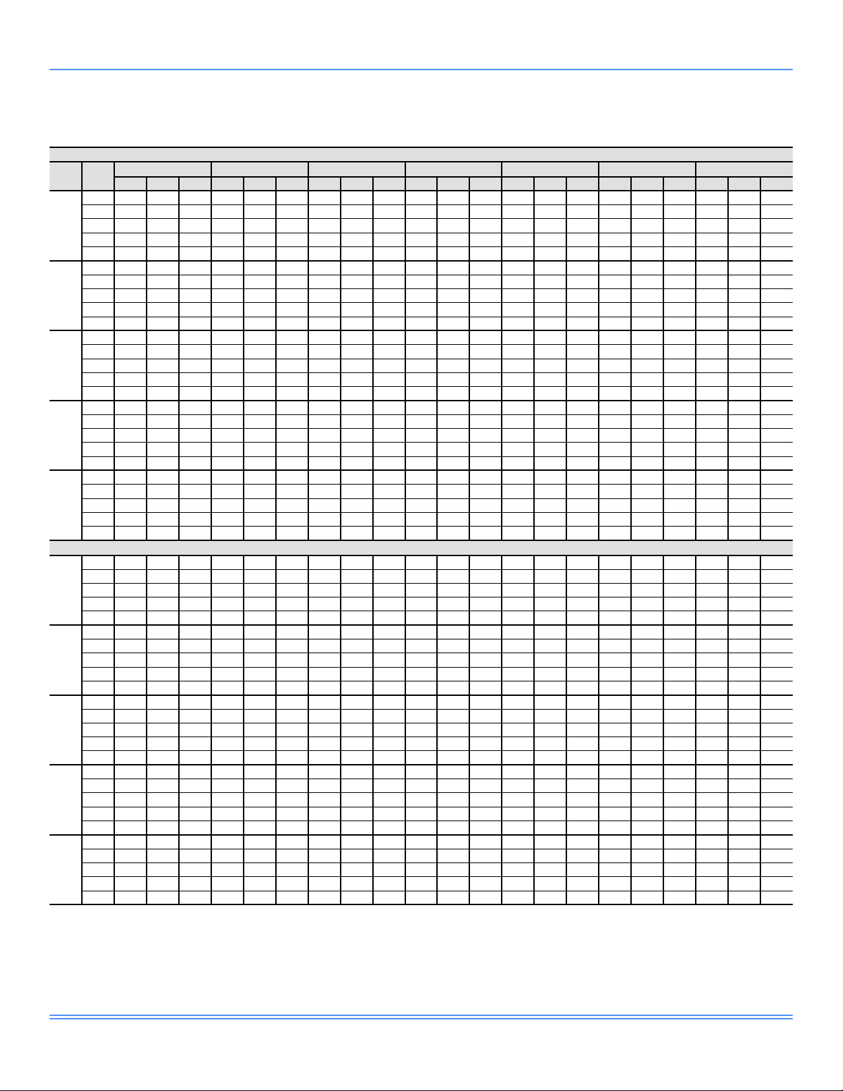
5513350-JTG-1018
Capacity Performance (Continued)
Table 5: Cooling Performance Data - 25 Ton High Efciency (Continued)
95°F Ambient Air Temperature
EWB
CFM
(°F)
77 320 197 22 318 169 22 318 141 22 317 113 22 - - - - - - - - 72 288 220 22 287 193 22 287 165 22 286 137 22 285 109 22 - - - - - 67 260 244 22 258 216 22 257 188 22 257 161 22 255 133 22 255 105 22 - - -
5,000
62 252 252 22 237 237 22 231 212 22 230 185 22 229 157 22 228 130 22 228 102 22
57 251 251 22 237 237 22 222 222 22 208 207 22
77 339 232 23 338 195 23 337 157 23 335 119 23 - - - - - - - - 72 309 266 22 307 229 22 305 191 22 304 154 22 302 116 22 - - - - - 67 290 290 22 279 262 22 276 225 22 274 188 22 274 151 22 272 11 3 22 - - -
6,750
62 290 290 22 273 273 22 256 256 22 249 222 22 247 185 22 246 148 22 244 110 22
57 290 290 22 272 272 22 256 256 22 239 239 22 225 219 22 221 182 22 220 145 22
77 351 266 23 350 220 23 347 172 23 345 125 23 - - - - - - - - 72 325 310 22 319 264 22 317 217 22 315 170 22 313 123 22 - - - - - 67 319 319 22 300 300 22 289 261 22 286 214 22 285 167 22 282 120 22 - - -
8,500
62 319 319 22 299 299 22 280 280 22 263 257 22 258 211 22 257 164 22 254 117 22
57 318 318 22 299 299 22 280 280 22 262 262 22 243 243 22 232 208 22 230 162 22
77 361 301 23 358 244 23 355 188 23 352 130 23 - - - - - - - - 72 342 342 23 329 298 23 325 242 23 323 185 23 320
67 341 341 23 320 320 22 300 293 22 294 239 22 292 182 22 289 126 22 - - 62 341 341 23 320 320 22 299 299 22 278 278 22 267 237 22 263 180 22 261 124 22
10,250
57 341 341 23 320 320 22 299 299 22 278 278 22 259 259 22 242 234 22 237 178 22
77 369 335 23 364 269 23 361 203 23 357 136 23 - - - - - - - - 72 359 359 23 339 330 23 332 267 23 328 200 23 325 134 23 - - - - - 67 359 359 23 336 336 23 314 314 22 301 264 22 297 198
62 358 358 23 336 336 23 314 314 22 292 292 22 274 261 22 269 196 22 266 129 22
12,000
57 358 358 23 335 335 23 314 314 22 292 292 22 272 272 22 251 251 22 242 193 22
77 299 185 25 298 157 25 297 129 25 296 101 25 - - - - - - - - 72 269 209 25 268 181 25 267 153 25 266 126 25 265 98 25 - - - - - 67 242 232 24 240 205 24 239 177 24 238 149 24 238 122 24 236 94 24 - - -
5,000
62 237 237 24 223 223 24 215 201 24 213 173 24 212 146
57 237 237 24 222 222 24 208 208 24 194 194 24 189 169 24 188 142 24 187 114 24
77 316 220 25 315 183 25 314 145 25 312 107 25 - - - - - - - - 72 288 254 25 286 217 25 284 180 25 283 142 25 281 105 25 - - - - - 67 274 274 25 260 251 25 257 214 25 255 176 25 254 139 25 252 101 25 - - -
6,750
62 274 274 25 257 257 25 240 240 24 231 211 24 228 173 24 227 136 24 226 99 24
57 273 273 25 256 256 25 240 240 24 223 223 24 208 206 24
77 327 254 25 326 208 25 324 160 25 321 113 25 - - - - - - - - 72 304 297 25 297 252 25 295 205 25 293 158 25 290 110 25 - - - - - 67 301 301 25 282 282 25 269 249 25 265 202 25 263 155 25 261 108 25 - - -
8,500
62 301 301 25 282 282 25 263 263 25 245 244 24 239 199 24 237 152 24 235 105 24
57 300 300 25 281 281 25 263 263 25 244 244 24 226 226 24 214 196 24 212 149 24
77 336 289 25 333 232 25 330 175 25 327 118 25 - - - - - - - - 72 322 322 25 307 286 25 302 230 25 299 173 25 296 116 25 - - - - - 67 321 321 25 301 301 25 281 279 25 273 227 25 270 170 25 267 11 3 25 - - 62 321 321 25 300 300 25 280 280 25 261 261 25 247 225 25 243 168 24 240 111 24
10,250
57 321 321 25 300 300 25 280 280 25 260 260 25 241 241 24 223 220 24 218 165 24
77 345 322 25 339 257 25 335 191 25 331 123 25 - - - - - - - - 72 339 339 25 317 315 25 308 255 25 304 188 25 301 122 25 67 338 338 25 316 316 25 294 294 25 280 252 25 275 186 25 271 11 9 25 - - 62 337 337 25 316 316 25 294 294 25 273 273 25 254 248 25 248 184 25 245 117 25
12,000
57 337 337 25 315 315 25 294 294 25 273 273 25 253 253 25 233 233 24 223 181 24
95°F EDB 90°F EDB 85°F EDB 80°F EDB 75°F EDB 70°F EDB 65°F EDB
TMBH SMBH kW TMBH SMBH kW TMBH SMBH kW TMBH SMBH kW TMBH SMBH kW TMBH SMBH kW TMBH SMBH kW
105°F Ambient Air Temperature
205 181 22 204 153 22 203 126 22
128 22 - - - - - -
22 294 131 22 - - -
24 211 118 24 211 90 24
203 170 24 202 133 24
- - - - -
NOTES:
Rated performance is at sea level. Cooling capacities are gross cooling capacities.
CFM = airow EWB = entering wet bulb air EDB = entering dry bulb air TMBH = total cooling capacity (MBH)
SMBH = sensible cooling capacity (MBH) kW = total input
26
Johnson Controls
Page 27
Capacity Performance (Continued)
Table 5: Cooling Performance Data - 25 Ton High Efciency (Continued)
115°F Ambient Air Temperature
EWB
CFM
(°F)
77 277 173 28 276 145 28 275 11 7 28 273 89 28 - - - - - - - - 72 248 197 27 248 169 27 246 141 27 246 114 27 244 86 27 - - - - - 67 225 220 27 221 193 27 220 165 27 219 138 27 219 110 27 217 82 27 - - -
5,000
62 222 222 27 208 208 27 197 189 27 195 161 27 194 134 27 193 106 27 192 78 27
57 221 221 27 207 207 27 193 193 27 179 179 27
77 292 208 28 291 170 28 289 133 28 287 95 28 - - - - - - - - 72 266 242 28 263 205 28 262 167 28 260 130 28 258 92 28 - - - - - 67 257 257 27 241 237 27 236 202 27 234 164 27 233 127 27 231 89 27 - - -
6,750
62 256 256 27 239 239 27 223 223 27 211 198 27 208 161 27 207 124 27 206 86 27
57 255 255 27 239 239 27 222 222 27 206 206 27 191 191 27 184 157 27 183 120 27
77 303 242 28 300 195 28 298 148 28 295 100 28 - - - - - - - - 72 283 282 28 274 239 28 271 193 28 269 145 28 266 98 28 - - - - - 67 282 282 28 263 263 28 248 236 27 244 190 27 242 143 27 239 95 27 - - -
8,500
62 281 281 28 263 263 28 244 244 27 226 226 27 218 187 27 216 140 27 213 93 27
57 281 281 28 262 262 28 244 244 27 226 226 27 209 209 27 195 183 27 191 136 27
77 311 276 28 307 220 28 304 163 28 300 105 28 - - - - - - - - 72 301 301 28 284 273 28 278 217 28 275 161 28 272
67 300 300 28 280 280 28 261 261 28 251 215 27 248 158 27 244 101 27 - - 62 300 300 28 280 280 28 260 260 28 241 241 27 226 212 27 222 156 27 219 99 27
10,250
57 299 299 28 279 279 28 260 260 28 241 241 27 222 222 27 204 204 27 197 152 27
77 319 308 28 312 244 28 308 178 28 304 111 28 - - - - - - - - 72 316 316 28 295 295 28 284 242 28 279 176 28 275 109 28 - - - - - 67 316 316 28 295 295 28 274 274 28 257 239 28 252 174
62 315 315 28 294 294 28 273 273 28 253 253 27 233 232 27 226 171 27 222 104 27
12,000
57 315 315 28 294 294 28 273 273 28 253 253 27 233 233 27 213 213 27 202 168 27
95°F EDB 90°F EDB 85°F EDB 80°F EDB 75°F EDB 70°F EDB 65°F EDB
TMBH SMBH kW TMBH SMBH kW TMBH SMBH kW TMBH SMBH kW TMBH SMBH kW TMBH SMBH kW TMBH SMBH kW
5513350-JTG-1018
172 157 27 170 130 27 170 102 27
103 28 - - - - - -
27 248 107 27 - - -
NOTES:
Rated performance is at sea level. Cooling capacities are gross cooling capacities.
CFM = airow EWB = entering wet bulb air EDB = entering dry bulb air TMBH = total cooling capacity (MBH)
SMBH = sensible cooling capacity (MBH) kW = total input
Johnson Controls
27
Page 28

5513350-JTG-1018
Capacity Performance (Continued)
Table 6: Cooling Performance Data - 25 Ton High Capacity
75°F Ambient Air Temperature
EWB
CFM
(°F)
77 372 220 21 372 193 21 371 165 21 371 138 21 - - - - - - - - 72 340 248 21 340 221 21 340 194 21 339 166 21 339 139 21 - - - - - 67 310 275 20 310 247 20 309 220 20 309 193 20 308 165 20 307 137 20 - - -
5,000
62 291 291 20 281 271 20 279 243 20 278 216 20 278 188 20 277 161 20 276 133 20
57 291 291 20 275 275 20 - - - - - 77 400 257 22 399 220 22 399 183 21 398 146 21 - - - - - - - - 72 367 295 21 367 258 21 366 222 21 366 185 21 365 148 21 - - - - - 67 340 332 21 336 295 21 335 258 21 334 221 21 333 184 21 332 147 21 - - -
6,750
62 337 337 21 318 318 21 305 292 20 303 255 20 302 218 20 300 181 20 295 142 20
57 336 336 21 318 318 21 300 300 20 282 282 20 273 251 20 272 214 20 270 177 20
77 418 293 22 417 246 22 416 200 22 414 153 22 - - - - - - - - 72 386 341 21 384 295 21 382 248 21 382 202 21 381 155 21 - - - - - 67 371 371 21 356 341 21 352 295 21 349 248 21 348 201 21 346 154 21 - - -
8,500
62 370 370 21 351 351 21 330 330 21 319 292 21 317 245 21 315 198 21 313 151 21
57 369 369 21 350 350 21 330 330 21 310 310 21 291 288 20 286 241 20 284 195 20
77 431 328 22 428 272 22 427 216 22 425 159 22 - - - - - - - - 72 402 385 22 397 330 21 394 274 21 393 218 21 391
67 397 397 21 377 377 21 365 330 21 361 273 21 359 217 21 357 161 21 - - 62 397 397 21 376 376 21 354 354 21 334 327 21 327 271 21 326 215 21 323 158 21
10,250
57 396 396 21 375 375 21 353 353 21 331 331 21 310 310 21 297 268 20 294 212 20
77 440 363 22 437 297 22 435 231 22 432 165 22 - - - - - - - - 72 420 420 22 407 365 22 403 299 22 401 234 22 398 167 21 - - - - - 67 419 419 22 397 397 21 376 364 21 369 299 21 367 233
62 418 418 22 396 396 21 373 373 21 349 349 21 336 296 21 333 231 21 330 164 21
12,000
57 417 417 22 395 395 21 372 372 21 349 349 21 325 325 21 306 293 20 302 228 20
77 358 214 23 358 187 23 357 160 23 357 132 23 - - - - - - - - 72 325 240 23 325 213 23 324 185 23 323 157 23 323 129 23 - - - - - 67 293 263 22 292 235 22 291 208 22 291 181 22 290 153 22 289 125 22 - - -
5,000
62 278 278 22 265 259 22 262 231 22 262 204 22 261 177
57 277 277 22 262 262 22 247 247 22 - - - - - - - - - - - 77 384 251 24 383 214 24 383 177 24 381 140 24 - - - - - - - - 72 350 287 23 349 250 23 347 212 23 347 175 23 345 137 23 - - - - - 67 322 320 23 317 283 23 315 246 23 314 209 23 313 171 23 3 11 134 23 - - -
6,750
62 321 321 23 303 303 23 288 280 22 284 243 22 283 206 22 282 168 22 280 131 22
57 320 320 23 302 302 23 285 285 22 267 267 22 256 239 22
77 400 287 24 398 240 24 398 194 24 395 146 24 - - - - - - - - 72 368 332 23 365 285 23 362 238 23 361 191 23 359 144 23 - - - - - 67 354 354 23 336 328 23 331 282 23 328 235 23 327 188 23 325 141 23 - - -
8,500
62 354 354 23 333 333 23 313 313 23 300 279 23 296 232 23 295 186 23 294 138 23
57 353 353 23 333 333 23 313 313 23 293 293 23 274 274 22 268 229 22 266 183 22
77 411 322 24 409 266 24 407 209 24 404 152 24 - - - - - - - - 72 384 375 24 376 320 23 373 263 23 371 207 23 368 150 23 - - - - - 67 380 380 24 358 358 23 343 317 23 338 260 23 336 204 23 334 147 23 - - 62 380 380 24 357 357 23 335 335 23 314 313 23 307 258 23 305 202 23 302 145 23
10,250
57 379 379 24 357 357 23 335 335 23 314 314 23 293 293 23 278 255 22 275 199 22
77 421 356 24 417 290 24 414 224 24 410 157 24 - - - - - - - - 72 403 403 24 386 354 24 380 288 24 377 222 24 374 155 23 67 402 402 24 377 377 24 354 349 23 346 285 23 343 219 23 340 153 23 - - 62 401 401 24 377 377 24 353 353 23 330 330 23 315 283 23 3 11 218 23 308 151 23
12,000
57 400 400 24 376 376 24 352 352 23 329 329 23 307 307 23 287 280 23 282 215 22
95°F EDB 90°F EDB 85°F EDB 80°F EDB 75°F EDB 70°F EDB 65°F EDB
TMBH SMBH kW TMBH SMBH kW TMBH SMBH kW TMBH SMBH kW TMBH SMBH kW TMBH SMBH kW TMBH SMBH kW
85°F Ambient Air Temperature
- - - - - - - - -
162 21 - - - - - -
21 364 167 21 - - -
22 260 149 22 260 121 22
255 202 22 253 165 22
- - - - -
NOTES:
Rated performance is at sea level. Cooling capacities are gross cooling capacities.
CFM = airow EWB = entering wet bulb air EDB = entering dry bulb air TMBH = total cooling capacity (MBH)
SMBH = sensible cooling capacity (MBH) kW = total input
28
Johnson Controls
Page 29

Capacity Performance (Continued)
Table 6: Cooling Performance Data - 25 Ton High Capacity (Continued)
95°F Ambient Air Temperature
EWB
CFM
(°F)
77 339 204 26 338 176 26 338 149 26 337 121 26 - - - - - - - - 72 305 227 25 305 200 25 304 172 25 303 144 25 302 117 25 - - - - - 67 274 250 25 273 222 25 272 195 25 271 167 25 270 139 25 269 111 25 - - -
5,000
62 262 262 25 248 246 25 244 219 24 243 191 24 243 164 24 242 136 24 241 108 24
57 263 263 25 248 248 25 233 233 24 - - 77 362 240 26 361 203 26 360 165 26 358 128 26 - - - - - - - - 72 328 274 26 327 237 25 325 199 25 324 162 25 323 124 25 - - - - - 67 303 303 25 296 269 25 293 232 25 292 194 25 291 157 25 289 120 25 - - -
6,750
62 304 304 25 286 286 25 269 266 25 264 229 25 263 192 25 262 155 25 260 117 25
57 304 304 25 286 286 25 269 269 25 252 252 25 239 227 24 237 190 24 235 153 24
77 376 275 26 374 228 26 372 181 26 370 133 26 - - - - - - - - 72 345 319 26 341 272 26 339 225 26 337 178 26 335 130 26 - - - - - 67 335 335 26 315 313 25 308 268 25 305 220 25 303 174 25 301 126 25 - - -
8,500
62 335 335 26 315 315 25 295 295 25 280 266 25 275 218 25 274 172 25 272 125 25
57 335 335 26 315 315 25 296 296 25 276 276 25 258 258 25 249 216 25 247 170 25
77 386 309 26 383 253 26 381 196 26 378 139 26 - - - - - - - - 72 361 360 26 351 306 26 348 250 26 345 193 26 343
67 359 359 26 337 337 26 319 302 25 314 246 25 312 189 25 309 132 25 - - 62 359 359 26 337 337 26 316 316 25 294 294 25 285 244 25 282 188 25 280 131 25
10,250
57 359 359 26 338 338 26 316 316 25 295 295 25 275 275 25 259 243 25 255 186 25
77 395 344 26 390 278 26 387 2 11 26 384 144 26 - - - - - - - - 72 380 380 26 361 340 26 355 275 26 352 208 26 349 142 26 - - - - - 67 379 379 26 354 354 26 331 331 26 321 271 26 318 205
62 379 379 26 355 355 26 332 332 26 309 309 25 293 269 25 288 203 25 285 137 25
12,000
57 379 379 26 355 355 26 332 332 26 310 310 25 289 289 25 268 266 25 261 202 25
77 318 192 28 316 164 28 316 136 28 314 108 28 - - - - - - - - 72 285 216 28 285 188 28 284 160 28 283 133 28 282 104 28 - - - - - 67 256 238 28 254 210 28 253 183 28 253 155 28 251 127 28 251 100 28 - - -
5,000
62 248 248 27 233 233 27 227 207 27 226 180 27 226 152
57 247 247 27 233 233 27 218 218 27 204 203 27 201 176 27 200 148 27 199 121 27
77 338 228 29 336 190 29 335 153 29 333 115 29 - - - - - - - - 72 307 261 28 305 224 28 303 187 28 302 150 28 300 112 28 - - - - - 67 286 286 28 276 257 28 273 220 28 271 182 28 270 145 28 268 108 28 - - -
6,750
62 287 287 28 269 269 28 252 252 28 246 217 27 243 180 27 243 143 27 241 106 27
57 286 286 28 269 269 28 252 252 28 235 235 27 221 214 27
77 350 262 29 348 215 29 346 168 29 344 120 29 - - - - - - - - 72 323 306 28 317 259 28 315 212 28 313 165 28 311 118 28 - - - - - 67 316 316 28 296 296 28 286 255 28 283 208 28 281 161 28 279 11 4 28 - - -
8,500
62 316 316 28 296 296 28 277 277 28 260 253 28 255 206 28 254 160 28 251 112 28
57 316 316 28 296 296 28 277 277 28 258 258 28 240 240 27 229 204 27 227 157 27
77 360 297 29 357 240 29 354 183 29 351 126 29 - - - - - - - - 72 340 340 29 327 294 29 324 237 29 321 181 28 318 124 28 - - - - - 67 339 339 29 317 317 28 297 289 28 291 234 28 289 177 28 286 120 28 - - 62 339 339 29 317 317 28 296 296 28 276 276 28 264 232 28 261 175 28 258 119 28
10,250
57 339 339 29 317 317 28 296 296 28 276 276 28 256 256 28 239 229 27 234 173 27
77 368 331 29 363 265 29 360 198 29 356 131 29 - - - - - - - - 72 358 358 29 337 327 29 330 262 29 326 196 29 323 129 29 67 356 356 29 333 333 29 3 11 311 28 298 259 28 294 192 28 291 126 28 - - 62 356 356 29 334 334 29 3 11 311 28 290 290 28 272 257 28 266 191 28 263 125 28
12,000
57 356 356 29 334 334 29 3 11 311 28 290 290 28 269 269 28 248 248 28 239 189 27
95°F EDB 90°F EDB 85°F EDB 80°F EDB 75°F EDB 70°F EDB 65°F EDB
TMBH SMBH kW TMBH SMBH kW TMBH SMBH kW TMBH SMBH kW TMBH SMBH kW TMBH SMBH kW TMBH SMBH kW
105°F Ambient Air Temperature
5513350-JTG-1018
- - - - - - - - -
136 26 - - - - - -
25 315 138 25 - - -
27 225 125 27 224 97 27
217 177 27 216 140 27
- - - - -
NOTES:
Rated performance is at sea level. Cooling capacities are gross cooling capacities.
CFM = airow EWB = entering wet bulb air EDB = entering dry bulb air TMBH = total cooling capacity (MBH)
SMBH = sensible cooling capacity (MBH) kW = total input
Johnson Controls
29
Page 30

5513350-JTG-1018
Capacity Performance (Continued)
Table 6: Cooling Performance Data - 25 Ton High Capacity (Continued)
115°F Ambient Air Temperature
EWB
CFM
(°F)
77 294 179 31 293 151 31 292 123 31 290 95 31 - - - - - - - - 72 263 203 31 263 176 31 262 148 31 261 120 31 260 92 31 - - - - - 67 237 227 31 235 199 31 234 172 31 233 144 31 232 116 31 231 88 31 - - -
5,000
62 232 232 31 217 217 30 208 195 30 207 167 30 206 140 30 205 11 2 30 204 84 30
57 231 231 31 216 216 30 202 202 30 188 188 30
77 311 214 32 310 177 32 308 139 32 306 101 32 - - - - - - - - 72 283 249 31 280 211 31 279 174 31 278 137 31 276 99 31 - - - - - 67 269 269 31 255 245 31 252 208 31 250 171 31 249 134 31 247 96 31 - - -
6,750
62 268 268 31 251 251 31 234 234 31 225 205 31 222 167 31 221 130 31 220 93 31
57 268 268 31 251 251 31 234 234 31 217 217 30 201 200 30 197 163 30 196 126 30
77 323 249 32 321 202 32 319 155 32 316 107 32 - - - - - - - - 72 299 293 32 292 246 32 290 199 31 288 152 31 285 105 31 - - - - - 67 296 296 32 277 277 31 264 243 31 260 196 31 258 149 31 256 102 31 - - -
8,500
62 296 296 32 276 276 31 258 258 31 239 238 31 233 193 31 231 146 31 229 99 31
57 295 295 32 276 276 31 257 257 31 238 238 31 220 220 31 208 190 30 205 143 30
77 332 283 32 328 227 32 326 170 32 322 112 32 - - - - - - - - 72 317 317 32 302 280 32 297 224 32 295 168 32 291
67 317 317 32 296 296 32 276 275 31 268 222 31 265 165 31 262 108 31 - - 62 316 316 32 295 295 32 275 275 31 255 255 31 241 219 31 237 162 31 235 106 31
10,250
57 316 316 32 295 295 32 275 275 31 255 255 31 235 235 31 217 214 31 211 159 30
77 340 317 32 334 251 32 330 185 32 326 118 32 - - - - - - - - 72 334 334 32 312 311 32 303 249 32 299 183 32 295 11 6 32 - - - - - 67 334 334 32 311 311 32 290 290 32 275 246 31 270 180
62 333 333 32 311 311 32 289 289 32 268 268 31 249 243 31 242 178 31 239 111 31
12,000
57 332 332 32 310 310 32 289 289 32 268 268 31 247 247 31 227 227 31 216 175 31
95°F EDB 90°F EDB 85°F EDB 80°F EDB 75°F EDB 70°F EDB 65°F EDB
TMBH SMBH kW TMBH SMBH kW TMBH SMBH kW TMBH SMBH kW TMBH SMBH kW TMBH SMBH kW TMBH SMBH kW
182 163 30 181 135 30 180 108 30
110 32 - - - - - -
31 266 114 31 - - -
NOTES:
Rated performance is at sea level. Cooling capacities are gross cooling capacities.
CFM = airow EWB = entering wet bulb air EDB = entering dry bulb air TMBH = total cooling capacity (MBH)
SMBH = sensible cooling capacity (MBH) kW = total input
30
Johnson Controls
Page 31

Capacity Performance (Continued)
Table 7: Cooling Performance Data - 30 Ton Standard Efficiency
75°F Ambient Air Temperature
EWB
CFM
(°F)
77 409 235 24 409 208 24 409 181 24 409 153 24 - - - - - - - - 72 373 263 24 374 236 24 374 209 24 374 182 24 374 155 24 - - - - - 67 342 291 23 342 264 23 341 237 23 342 210 23 341 182 23 341 155 23 - - -
5,000
62 315 315 23 - - - - - - - - - - - - - - - - - 57 314 314 23 - - - - - - - - 77 442 273 25 442 237 25 442 200 25 441 162 25 - - - - - - - - 72 406 311 24 406 275 24 406 238 24 406 202 24 405 164 24 - - - - - 67 375 349 24 372 312 24 372 276 24 372 239 24 371 202 24 370 165 24 - - -
6,750
62 365 365 24 346 346 23 339 310 23 337 273 23 336 236 23 336 199 23 335 162 23
57 364 364 24 345 345 23 326 326 23 309 306 23
77 464 309 25 464 263 25 462 216 25 462 170 25 - - - - - - - - 72 428 357 24 427 311 24 426 265 24 426 219 24 424 172 24 - - - - - 67 402 402 24 394 359 24 392 313 24 391 266 24 390 220 24 388 173 24 - - -
8,500
62 402 402 24 381 381 24 362 357 24 357 310 24 355 264 24 354 217 24 352 170 24
57 401 401 24 381 381 24 360 360 24 339 339 23 324 307 23 322 260 23 321 214 23
77 479 345 25 478 289 25 476 233 25 475 176 25 - - - - - - - - 72 445 403 25 442 347 25 440 291 25 439 235 25 438 179 25 - - - - - 67
62 431 431 25 410 410 24 387 387 24 372 346 24 368 290 24 367 234 24 365 177 24
10,250
57 431 431 25 409 409 24 386 386 24 364 364 24 342 341 23 334 287 23 333 231 23
77 491 380 25 489 314 25 487 248 25 485 182 25 - - - - - - - - 72 461 447 25 454 382 25 451 317 25 449 251 25 447 185 25 - - - - - 67 457 457 25 434 434 25 419 384 24 414 318 24 412 252 24 410 186 24 - - 62 456
12,000
57 455 455 25 432 432 25 408 408 24 384 384 24 360 360 24 345 313 24 341 247 23
77 394 229 27 394 202 27 394 175 27 395 147 27 - - - - - - - - 72 360 257 26 359 229 26 359 202 26 359 174 26 358 146 26 - - - - - 67 325 279 26 324 252 26 323 224 26 322 197 26 322 169 26 321 141 26 - - -
5,000
62 300 300 26 293 275 25 291 248 25 290 220 25 290 193 25 290 165 25 289 138 25
57 299
77 425 267 27 425 230 27 425 193 27 424 156 27 - - - - - - - - 72 390 304 27 389 267 27 388 230 27 387 192 27 386 155 27 - - - - - 67 356 337 26 352 300 26 351 263 26 350 226 26 350 188 26 348 151 26 - - -
6,750
62 348 348 26 329 329 26 319 297 26 317 259 26 317 223 26 316 186 26 315 148 26
57 347 347 26 329 329 26 310 310 26 292 292 25 287 256 25 286 219 25 285 182 25
77 445 303 27 445 256 27 443 210 27 443 163 27 - - - - - - - - 72 410 349 27 407 302 27 406 256 27 404 209 27 403 162 27 - - - - - 67 385 385 27 373 346 27 369 299 26 368 252 26 367 205 26 365 158 26 - - -
8,500
62 385 385 27 363 363 26 342 342 26 336 297 26 334 250 26 333 203 26 331 156 26
57 384 384 27 363 363 26 342 342 26 322 322 26 305 294 26 302 247 26 301 201 26
77 459 338 28 458 282 28 456 226 28 455 169 28 - - - - - - - - 72 426 394
67 415 415 27 391 389 27 383 334 27 380 278 27 378 221 27 376 165 27 - - 62 414 414 27 391 391 27 368 368 26 350 332 26 346 276 26 343 220 26 342 163 26
10,250
57 414 414 27 390 390 27 368 368 26 345 345 26 323 323 26 314 274 26 312 217 26
77 470 373 28 467 307 28 465 241 28 462 175 28 - - - - - - - - 72 441 437 27 432 372 27 428 306 27 425 240 27 422 173 27 - - - - - 67 439 439 27
62 438 438 27 413 413 27 388 388 27 364 364 26 355 302 26 352 236 26 350 170 26
12,000
57 438 438 27 413 413 27 388 388 27 364 364 26 341 341 26 324 300 26 319 234 26
95°F EDB 90°F EDB 85°F EDB 80°F EDB 75°F EDB 70°F EDB 65°F EDB
TMBH SMBH kW TMBH SMBH kW TMBH SMBH kW TMBH SMBH kW TMBH SMBH kW TMBH SMBH kW TMBH SMBH kW
432 432 25 413 404 24 407 349 24 404 292 24 403 236 24 401 180 24 - - -
456 25 433 433 25 409 409 24 385 381 24 378 316 24 375 250 24 373 184 24
85°F Ambient Air Temperature
299 26 - - - - - - - - - - - - - - - - - -
27 421 337 27 419 281 27 416 224 27 415 168 27 - - - - - -
413 413 27 395 369 27 389 303 27 386 237 27 384 171 27 - - -
5513350-JTG-1018
- - - - - - - - -
NOTES:
Rated performance is at sea level. Cooling capacities are gross cooling capacities.
CFM = airow EWB = entering wet bulb air EDB = entering dry bulb air TMBH = total cooling capacity (MBH)
SMBH = sensible cooling capacity (MBH) kW = total input
Johnson Controls
31
Page 32

5513350-JTG-1018
Capacity Performance (Continued)
Table 7: Cooling Performance Data - 30 Ton Standard Efciency (Continued)
95°F Ambient Air Temperature
EWB
CFM
(°F)
77 377 220 30 376 193 30 376 165 30 375 137 30 - - - - - - - - 72 339 243 29 338 215 29 338 188 29 337 160 29 336 132 29 - - - - - 67 303 264 29 301 236 29 301 209 29 300 181 29 300 153 29 299 125 29 - - -
5,000
62 283 283 28 273 261 28 271 233 28 270 205 28 270 178 28 269 150 28 269 123 28
57 284 284 28 269 269 28 - - - - - 77 404 257 30 404 220 30 402 182 30 401 144 30 - - - - - - - - 72 366 290 30 365 253 30 364 215 30 363 178 30 362 140 29 - - - - - 67 332 321 29 328 284 29 327 247 29 326 209 29 325 172 29 323 134 29 - - -
6,750
62 329 329 29 310 310 29 298 281 29 295 244 29 294 207 29 294 170 29 292 133 29
57 330 330 29 311 311 29 293 293 29 275 275 28 268 243 28 266 206 28 266 169 28
77 422 292 30 421 245 30 419 198 30 417 151 30 - - - - - - - - 72 385 335 30 382 288 30 381 241 30 379 194 30 377 147 30 - - - - - 67 364 364 30 348 330 29 344 283 29 342 236 29 340 189 29 339 142 29 - - -
8,500
62 364 364 30 343 343 29 322 322 29 312 281 29 310 234 29 309 188 29 307 141 29
57 365 365 30 344 344 29 324 324 29 304 304 29 286 280 28 282 234 28 280 187 28
77 434 326 31 432 270 30 430 213 30 427 156 30 - - - - - - - - 72 400 379 30 395 323 30 392 266 30 390 210 30 387
67 392 392 30 368 368 30 357 318 30 353 261 29 351 205 29 349 148 29 - - 62 393 393 30 369 369 30 346 346 29 326 317 29 321 260 29 319 204 29 317 147 29
10,250
57 393 393 30 370 370 30 348 348 29 326 326 29 305 305 29 293 260 29 290 204 29
77 444 361 31 440 295 31 438 228 31 434 161 31 - - - - - - - - 72 417 417 30 405 358 30 400 291 30 397 225 30 394 158 30 - - - - - 67 415 415 30 389 389 30 368 352 30 362 287 30 358 220
62 416 416 30 390 390 30 366 366 30 342 342 29 330 286 29 326 220 29 324 153 29
12,000
57 416 416 30 391 391 30 367 367 30 344 344 29 321 321 29 302 286 29 297 220 29
77 354 207 33 353 180 33 353 152 33 352 124 33 - - - - - - - - 72 317 230 32 317 203 32 317 175 32 316 148 32 315 119 32 - - - - - 67 283 251 32 282 224 32 281 196 32 281 169 32 280 141 32 279 11 3 32 - - -
5,000
62 268 268 32 255 249 32 253 221 31 252 194 31 252 166
57 268 268 32 253 253 31 237 237 31 - - - - - - - - - - - 77 379 244 33 378 206 33 377 169 33 376 131 33 - - - - - - - - 72 343 277 33 342 240 33 341 203 33 339 165 33 338 128 33 - - - - - 67 312 308 32 307 271 32 305 234 32 304 197 32 303 160 32 302 122 32 - - -
6,750
62 311 311 32 293 293 32 278 269 32 275 232 32 274 195 32 274 158 32 272 121 32
57 312 312 32 293 293 32 275 275 32 258 258 32 248 229 31
77 395 278 34 393 232 34 392 184 34 389 137 34 - - - - - - - - 72 361 322 33 357 275 33 356 228 33 354 181 33 352 134 33 - - - - - 67 344 344 33 326 317 33 321 270 33 319 223 33 317 176 33 316 129 33 - - -
8,500
62 345 345 33 324 324 33 304 304 32 292 269 32 289 222 32 287 175 32 286 128 32
57 345 345 33 325 325 33 304 304 32 285 285 32 265 265 32 260 220 32 258 173 32
77 406 313 34 403 256 34 402 200 34 399 142 34 - - - - - - - - 72 376 366 33 369 310 33 366 253 33 364 197 33 361 140 33 - - - - - 67 371 371 33 348 348 33 333 305 33 329 249 33 327 192 33 324 135 33 - - 62 372 372 33 349 349 33 327 327 33 306 303 32 299 248 32 296 191 32 294 135 32
10,250
57 372 372 33 349 349 33 327 327 33 306 306 32 285 285 32 271 246 32 267 189 32
77 416 347 34 411 281 34 409 215 34 405 148 34 - - - - - - - - 72 395 395 34 379 344 33 373 278 33 371 212 33 368 145 33 67 392 392 34 368 368 33 345 339 33 337 274 33 334 208 33 331 141 33 - - 62 393 393 34 369 369 33 345 345 33 322 322 33 307 273 32 303 207 32 301 141 32
12,000
57 393 393 34 369 369 33 345 345 33 322 322 33 300 300 32 280 271 32 274 206 32
95°F EDB 90°F EDB 85°F EDB 80°F EDB 75°F EDB 70°F EDB 65°F EDB
TMBH SMBH kW TMBH SMBH kW TMBH SMBH kW TMBH SMBH kW TMBH SMBH kW TMBH SMBH kW TMBH SMBH kW
- - - - - - - - -
105°F Ambient Air Temperature
153 30 - - - - - -
30 356 154 30 - - -
31 251 139 31 251 111 31
246 192 31 245 155 31
- - - - -
NOTES:
Rated performance is at sea level. Cooling capacities are gross cooling capacities.
CFM = airow EWB = entering wet bulb air EDB = entering dry bulb air TMBH = total cooling capacity (MBH)
SMBH = sensible cooling capacity (MBH) kW = total input
32
Johnson Controls
Page 33

Capacity Performance (Continued)
Table 7: Cooling Performance Data - 30 Ton Standard Efciency (Continued)
115°F Ambient Air Temperature
EWB
CFM
(°F)
77 329 194 37 328 166 37 327 138 37 327 110 37 - - - - - - - - 72 295 217 36 294 190 36 294 162 36 293 134 36 292 106 36 - - - - - 67 264 240 36 263 213 36 262 185 36 262 158 36 261 130 36 260 102 36 - - -
5,000
62 251 251 36 236 236 35 233 208 35 232 181 35 232 153 35 231 126 35 230 98 35
57 251 251 35 236 236 35 220 220 35 207 203 35
77 352 230 37 351 192 37 349 155 37 348 117 37 - - - - - - - - 72 318 263 37 317 226 37 316 189 37 314 152 37 313 114 37 - - - - - 67 293 293 36 286 260 36 284 223 36 283 186 36 282 148 36 281 111 36 - - -
6,750
62 293 293 36 275 275 36 258 256 36 254 219 36 252 182 36 251 145 36 246 106 36
57 292 292 36 274 274 36 256 256 36 239 239 35 226 215 35 224 178 35 223 141 35
77 366 264 37 364 217 37 363 170 37 360 123 37 - - - - - - - - 72 335 309 37 331 262 37 329 215 37 328 168 37 325 120 37 - - - - - 67 325 325 37 305 304 36 298 259 36 296 212 36 294 165 36 292 11 8 36 - - -
8,500
62 324 324 37 304 304 36 284 284 36 269 255 36 265 209 36 264 162 36 262 115 36
57 324 324 37 303 303 36 284 284 36 264 264 36 245 245 36 237 205 35 235 158 35
77 377 299 38 373 242 38 371 186 38 368 128 38 - - - - - - - - 72 351 350 37 342 296 37 338 240 37 336 183 37 334
67 350 350 37 328 328 37 310 294 37 305 237 36 303 181 36 301 124 36 - - 62 349 349 37 327 327 37 305 305 36 284 284 36 275 234 36 272 178 36 270 121 36
10,250
57 348 348 37 326 326 37 305 305 36 284 284 36 263 263 36 247 231 36 243 175 36
77 385 333 38 380 267 38 378 201 38 374 134 38 - - - - - - - - 72 371 371 38 352 331 37 345 264 37 343 199 37 339 132 37 - - - - - 67 370 370 38 346 346 37 323 323 37 312 262 37 309 196
62 369 369 38 345 345 37 322 322 37 300 300 36 282 259 36 278 194 36 276 127 36
12,000
57 369 369 38 345 345 37 322 322 37 299 299 36 277 277 36 255 254 36 249 191 36
95°F EDB 90°F EDB 85°F EDB 80°F EDB 75°F EDB 70°F EDB 65°F EDB
TMBH SMBH kW TMBH SMBH kW TMBH SMBH kW TMBH SMBH kW TMBH SMBH kW TMBH SMBH kW TMBH SMBH kW
205 176 35 205 149 35 204 121 35
5513350-JTG-1018
126 37 - - - - - -
37 306 130 37 - - -
NOTES:
Rated performance is at sea level. Cooling capacities are gross cooling capacities.
CFM = airow EWB = entering wet bulb air EDB = entering dry bulb air TMBH = total cooling capacity (MBH)
SMBH = sensible cooling capacity (MBH) kW = total input
Johnson Controls
33
Page 34

5513350-JTG-1018
Capacity Performance (Continued)
Table 8: Cooling Performance Data - 30 Ton High Efficiency
75°F Ambient Air Temperature
EWB
CFM
(°F)
77 408 235 23 408 208 23 408 181 23 409 154 23 - - - - - - - - 72 373 263 23 373 236 23 373 209 23 373 182 23 373 155 23 - - - - - 67 340 290 22 341 264 22 340 237 22 340 210 22 340 182 22 340 154 22 - - -
5,000
62 313 313 22 308 287 22 308 260 22 307 232 22 306 205 22 306 177 22 306 150 22
57 312 312 22 - - - - - - - - 77 442 274 23 442 237 23 442 200 23 442 163 23 - - - - - - - - 72 405 312 23 405 275 23 405 239 23 405 202 23 405 165 23 - - - - - 67 374 350 23 372 313 23 371 276 23 371 240 23 371 202 23 368 167 23 - - -
6,750
62 364 364 23 345 345 22 338 310 22 336 273 22 336 236 22 335 199 22 334 161 22
57 363 363 23 344 344 22 325 325 22 307 306 22 304 269 22 303 232 22 302 195 22
77 464 310 24 464 264 24 463 217 24 462 171 24 - - - - - - - - 72 428 358 23 426 312 23 426 266 23 425 219 23 425 173 23 - - - - - 67 402 402 23 393 360 23 392 313 23 391 267 23 390 220 23 388 173 23 - - -
8,500
62 401 401 23 381 381 23 360 358 23 356 310 23 354 264 23 354 217 23 349 169 23
57 400 400 23 380 380 23 359 359 23 338 338 22 323 307 22 321 260 22 320 214 22
77 479 346 24 478 290 24 477 234 24 475 177 24 - - - - - - - - 72 445 404 23 441 348 23 440 292 23 439 236 23 438
67 432 432 23 412 406 23 406 350 23 404 293 23 402 237 23 401 180 23 - - 62 431 431 23 410 410 23 387 387 23 371 347 23 367 290 23 366 234 23 364 178 23
10,250
57 430 430 23 409 409 23 386 386 23 363 363 23 341 341 22 334 287 22 332 231 22
77 491 382 24 489 316 24 487 250 24 485 183 24 - - - - - - - - 72 460 450 24 453 384 23 451 318 23 449 252 23 447 186 23 - - - - - 67 457 457 24 434 434 23 418 385 23 414 319 23 412 253
62 456 456 24 433 433 23 409 409 23 385 383 23 378 317 23 375 250 23 373 184 23
12,000
57 455 455 24 432 432 23 408 408 23 384 384 23 360 360 23 344 314 22 340 247 22
77 394 230 26 395 203 26 395 175 26 395 148 26 - - - - - - - - 72 360 257 25 359 229 25 359 202 25 358 174 25 358 146 25 - - - - - 67 323 279 25 323 252 25 322 224 25 322 197 25 321 169 25 321 141 25 - - -
5,000
62 298 298 25 291 275 24 290 247 24 289 220 24 289 192
57 298 298 25 282 282 24 - - - - - - - - - - - - - - 77 426 268 26 426 231 26 426 194 26 425 157 26 - - - - - - - - 72 390 305 25 389 268 25 389 230 25 388 193 25 387 155 25 - - - - - 67 355 338 25 352 300 25 351 263 25 350 226 25 350 189 25 349 151 25 - - -
6,750
62 347 347 25 328 328 25 318 297 25 317 260 25 316 223 25 316 186 25 315 148 25
57 347 347 25 328 328 25 309 309 25 291 291 25 286 256 24
77 447 304 26 446 258 26 445 2 11 26 444 164 26 - - - - - - - - 72 410 351 26 408 304 26 407 257 26 406 210 26 405 163 26 - - - - - 67 385 385 25 373 347 25 370 300 25 368 253 25 367 206 25 366 159 25 - - -
8,500
62 385 385 25 363 363 25 342 342 25 335 297 25 334 251 25 333 204 25 331 157 25
57 384 384 25 363 363 25 342 342 25 321 321 25 304 294 25 302 247 25 301 201 25
77 461 340 26 460 284 26 458 227 26 456 171 26 - - - - - - - - 72 426 396 26 422 339 26 420 283 26 418 226 26 416 169 26 - - - - - 67 416 416 26 392 392 26 384 336 25 381 279 25 379 223 25 377 166 25 - - 62 415 415 26 391 391 26 368 368 25 350 334 25 346 277 25 344 220 25 342 164 25
10,250
57 414 414 26 391 391 26 368 368 25 345 345 25 323 323 25 314 274 25 311 218 25
77 472 375 26 469 309 26 468 243 26 465 176 26 - - - - - - - - 72 442 440 26 433 374 26 429 308 26 427 241 26 424 175 26 67 440 440 26 414 414 26 395 372 26 390 305 26 387 238 26 385 172 26 - - 62 440 440 26 414 414 26 389 389 26 365 365 25 355 303 25 352 237 25 350 170 25
12,000
57 439 439 26 414 414 26 389 389 26 365 365 25 341 341 25 323 301 25 320 234 25
95°F EDB 90°F EDB 85°F EDB 80°F EDB 75°F EDB 70°F EDB 65°F EDB
TMBH SMBH kW TMBH SMBH kW TMBH SMBH kW TMBH SMBH kW TMBH SMBH kW TMBH SMBH kW TMBH SMBH kW
85°F Ambient Air Temperature
- - - - - - - - -
180 23 - - - - - -
23 409 186 23 - - -
24 289 165 24 288 137 24
285 219 24 284 182 24
- - - - -
NOTES:
Rated performance is at sea level. Cooling capacities are gross cooling capacities.
CFM = airow EWB = entering wet bulb air EDB = entering dry bulb air TMBH = total cooling capacity (MBH)
SMBH = sensible cooling capacity (MBH) kW = total input
34
Johnson Controls
Page 35

Capacity Performance (Continued)
Table 8: Cooling Performance Data - 30 Ton High Efciency (Continued)
95°F Ambient Air Temperature
EWB
CFM
(°F)
77 377 221 28 377 194 28 376 166 28 375 138 28 - - - - - - - - 72 338 243 28 338 216 28 338 188 28 337 160 28 336 132 28 - - - - - 67 302 264 27 301 236 27 300 209 27 300 181 27 299 153 27 299 126 27 - - -
5,000
62 282 282 27 271 260 27 270 233 27 269 205 27 269 178 27 269 150 27 268 122 27
57 283 283 27 267 267 27 252 252 27 - - 77 406 258 29 405 221 29 404 183 29 403 146 29 - - - - - - - - 72 367 291 28 366 254 28 365 216 28 364 179 28 363 141 28 - - - - - 67 332 322 28 328 285 28 327 247 28 326 210 28 326 173 28 324 135 28 - - -
6,750
62 329 329 28 310 310 28 297 282 27 295 245 27 294 208 27 294 171 27 288 132 27
57 329 329 28 311 311 28 292 292 27 275 275 27 267 243 27 266 206 27 265 169 27
77 424 294 29 423 247 29 421 199 29 419 152 29 - - - - - - - - 72 386 337 29 383 289 29 382 243 29 381 195 29 379 148 28 - - - - - 67 364 364 28 348 331 28 345 284 28 343 237 28 341 190 28 340 143 28 - - -
8,500
62 365 365 28 343 343 28 322 322 28 312 282 28 310 235 28 309 188 28 308 141 28
57 365 365 28 344 344 28 324 324 28 303 303 28 285 281 27 281 234 27 280 187 27
77 436 329 29 434 272 29 432 215 29 430 158 29 - - - - - - - - 72 401 382 29 396 325 29 394 268 29 392 211 29 389
67 393 393 29 369 369 28 358 320 28 354 263 28 352 206 28 350 149 28 - - 62 394 394 29 370 370 28 347 347 28 326 319 28 322 262 28 319 205 28 318 148 28
10,250
57 394 394 29 371 371 28 348 348 28 326 326 28 304 304 28 293 261 27 290 204 27
77 446 364 29 442 297 29 440 230 29 437 163 29 - - - - - - - - 72 419 419 29 407 360 29 402 293 29 400 227 29 397 160 29 - - - - - 67 417 417 29 391 391 29 369 355 28 363 288 28 360 222
62 417 417 29 392 392 29 367 367 28 343 343 28 331 287 28 327 221 28 325 155 28
12,000
57 418 418 29 393 393 29 368 368 28 344 344 28 321 321 28 302 287 28 298 221 28
77 354 208 32 354 181 32 353 153 32 353 125 32 - - - - - - - - 72 317 231 31 317 203 31 317 176 31 316 148 31 315 120 31 - - - - - 67 283 252 31 282 224 31 281 197 31 281 169 31 280 141 31 279 11 3 31 - - -
5,000
62 267 267 30 254 249 30 253 221 30 252 194 30 251 166
57 267 267 30 252 252 30 237 237 30 226 217 30 224 190 30 224 162 30 224 135 30
77 381 245 32 380 208 32 379 170 32 378 132 32 - - - - - - - - 72 343 278 31 342 241 31 342 204 31 341 166 31 340 129 31 - - - - - 67 311 310 31 307 272 31 306 235 31 305 198 31 304 160 31 303 123 31 - - -
6,750
62 311 311 31 293 293 31 277 270 31 275 233 30 274 196 30 274 159 30 273 121 30
57 311 311 31 293 293 31 275 275 30 257 257 30 247 230 30
77 397 280 32 396 233 32 394 186 32 392 138 32 - - - - - - - - 72 361 324 32 359 277 32 357 230 32 356 183 32 354 135 32 - - - - - 67 345 345 32 326 319 31 322 271 31 320 224 31 319 177 31 317 130 31 - - -
8,500
62 345 345 32 325 325 31 304 304 31 291 270 31 289 223 31 288 176 31 286 129 31
57 345 345 31 325 325 31 304 304 31 285 285 31 265 265 30 260 220 30 259 173 30
77 409 315 32 406 258 32 404 201 32 401 144 32 - - - - - - - - 72 377 369 32 371 312 32 368 255 32 366 198 32 363 141 32 - - - - - 67 372 372 32 349 349 32 334 307 31 331 250 31 328 193 31 326 136 31 - - 62 373 373 32 350 350 32 327 327 31 305 305 31 300 249 31 297 193 31 295 136 31
10,250
57 373 373 32 350 350 32 328 328 31 306 306 31 285 285 31 271 247 30 268 190 30
77 418 350 33 413 283 33 4 11 217 33 407 149 32 - - - - - - - - 72 397 397 32 381 347 32 375 280 32 373 214 32 369 147 32 67 394 394 32 369 369 32 345 342 32 338 276 31 336 209 31 332 142 31 - - 62 395 395 32 370 370 32 346 346 32 323 323 31 308 275 31 304 208 31 302 142 31
12,000
57 395 395 32 370 370 32 346 346 32 323 323 31 300 300 31 279 273 31 275 207 31
95°F EDB 90°F EDB 85°F EDB 80°F EDB 75°F EDB 70°F EDB 65°F EDB
TMBH SMBH kW TMBH SMBH kW TMBH SMBH kW TMBH SMBH kW TMBH SMBH kW TMBH SMBH kW TMBH SMBH kW
105°F Ambient Air Temperature
5513350-JTG-1018
- - - - - - - - -
154 29 - - - - - -
28 357 155 28 - - -
30 251 139 30 250 111 30
246 192 30 245 156 30
- - - - -
NOTES:
Rated performance is at sea level. Cooling capacities are gross cooling capacities.
CFM = airow EWB = entering wet bulb air EDB = entering dry bulb air TMBH = total cooling capacity (MBH)
SMBH = sensible cooling capacity (MBH) kW = total input
Johnson Controls
35
Page 36

5513350-JTG-1018
Capacity Performance (Continued)
Table 8: Cooling Performance Data - 30 Ton High Efciency (Continued)
115°F Ambient Air Temperature
EWB
CFM
(°F)
77 330 195 35 329 167 35 328 139 35 328 111 35 - - - - - - - - 72 295 218 35 295 190 35 294 163 35 294 135 35 293 107 35 - - - - - 67 264 241 34 263 213 34 262 186 34 262 158 34 261 131 34 261 103 34 - - -
5,000
62 251 251 34 236 236 34 233 209 34 232 181 34 232 154 34 232 126 34 231 98 34
57 250 250 34 235 235 34 220 220 33 206 204 33
77 353 231 36 352 194 36 351 156 36 350 118 36 - - - - - - - - 72 319 264 35 317 227 35 317 190 35 316 153 35 314 115 35 - - - - - 67 293 293 35 286 261 34 284 224 34 284 186 34 283 149 34 281 11 2 34 - - -
6,750
62 293 293 35 275 275 34 257 257 34 254 220 34 253 183 34 252 145 34 247 107 34
57 292 292 35 274 274 34 256 256 34 239 239 34 226 216 34 224 178 33 224 141 33
77 368 266 36 366 219 36 365 172 36 363 124 36 - - - - - - - - 72 335 310 35 332 263 35 331 216 35 329 169 35 327 122 35 - - - - - 67 325 325 35 305 305 35 299 260 35 297 213 35 296 166 35 294 11 9 35 - - -
8,500
62 325 325 35 304 304 35 284 284 34 269 257 34 266 210 34 265 163 34 263 116 34
57 324 324 35 304 304 35 284 284 34 264 264 34 245 245 34 237 206 34 236 159 34
77 379 301 36 375 244 36 374 187 36 370 130 36 - - - - - - - - 72 352 352 36 343 298 35 340 241 35 338 185 35 335
67 351 351 36 328 328 35 3 11 296 35 306 239 35 305 182 35 302 125 35 - - 62 350 350 36 328 328 35 306 306 35 285 285 34 276 236 34 273 179 34 271 122 34
10,250
57 349 349 36 327 327 35 305 305 35 284 284 34 263 263 34 247 232 34 244 176 34
77 387 336 36 383 269 36 380 202 36 376 135 36 - - - - - - - - 72 372 372 36 353 333 36 347 267 36 344 200 36 341 133 35 - - - - - 67 371 371 36 347 347 36 324 324 35 314 264 35 311 198
62 371 371 36 347 347 36 323 323 35 300 300 35 283 261 34 280 195 34 276 128 34
12,000
57 370 370 36 346 346 36 323 323 35 300 300 35 278 278 34 256 256 34 250 192 34
95°F EDB 90°F EDB 85°F EDB 80°F EDB 75°F EDB 70°F EDB 65°F EDB
TMBH SMBH kW TMBH SMBH kW TMBH SMBH kW TMBH SMBH kW TMBH SMBH kW TMBH SMBH kW TMBH SMBH kW
205 176 33 205 149 33 204 122 33
127 35 - - - - - -
35 308 131 35 - - -
NOTES:
Rated performance is at sea level. Cooling capacities are gross cooling capacities.
CFM = airow EWB = entering wet bulb air EDB = entering dry bulb air TMBH = total cooling capacity (MBH)
SMBH = sensible cooling capacity (MBH) kW = total input
36
Johnson Controls
Page 37

Capacity Performance (Continued)
Table 9: Cooling Performance Data - 30 Ton High Capacity
75°F Ambient Air Temperature
EWB
CFM
(°F)
77 435 247 26 436 220 26 436 193 26 436 165 26 - - - - - - - - 72 397 275 25 397 248 25 397 221 25 398 194 25 398 166 25 - - - - - -
5,000
67 362 302 25 363 275 25 363 248 25 363 221 25 362 194 25 362 166 25 - - 77 475 287 26 475 250 26 475 213 26 474 176 26 - - - - - - - - 72 435 324 26 435 288 26 435 252 26 435 215
67 400 362 25 399 326 25 398 289 25 398 252 25 398 215 25 397 178 25 - - -
6,750
62 383 383 25 365 360 25 362 323 25 361 285 25 360 248 25 360 212 25 359 174 25
57 381 381 25 362 362 25 343 343 24 - - - - - - - - - - - 77 500 324 27 500 277 27 500 231 27 499 184 27 - - - - - - - - 72 460 372 26 459 325 26 459 279 26 459 233 26 458 186 26 - - - - - 67 428 420 26 423 373 26 422 327 26 421 280 25
8,500
62 425 425 26 403 403 25 386 371 25 383 324 25 382 277 25 381 231 25 380 184 25
57 424 424 26 402 402 25 380 380 25 359 359 25 347 320 25 346 273 25 345 227 25
77 518 360 27 517 304 27 516 247 27 515 191 27 - - - - - - - - 72 479 418 26 477 362 26 476 306 26 475 250 26 474 193 26 - - - - - 67 459 459 26 442 420 26 439 363 26 437 307 26 436 251 26 434 194 26 - - 62 458 458 26 435 435 26 4 11 411 25 400 361 25 397
10,250
57 457 457 26 434 434 26 410 410 25 386 386 25 365 358 25 361 301 25 359 245 25
77 532 395 27 530 329 27 528 263 27 526 197 27 - - - - - - - - 72 495 464 27 490 397 27 488 332 27 486 266 26 485 200 26 - - - - - 67 486 486 26 462 462 26 452 399 26 449 333 26 446 267 26 444 200 26 - - 62 485 485 26 461 461 26 435 435 26 414 397 25 409 331 25 406 264 25 405 198 25
12,000
57 484 484 26 460 460 26 434 434 26 409 409 25 384 384
77 421 241 28 421 214 28 421 186 28 421 159 28 - - - - - - - - 72 383 268 28 383 240 28 382 213 28 382 185 28 382 157 28 - - - - - 67 343 288 27 342 261 27 341 233 27 341 205 27 340 178 27 340 150 27 - - -
5,000
62 312 312 27 309 284 27 308 257 27 308 229 27 307 202 27 307 174 27 306 147 27
57 312 312 27 - - - - - - - - - - - - - - - - - 77 458 280 29 458 243 29 458 206 29 457 169 29 - - - - - - - - 72 418 317 28 418 280 28 417 243 28 417 205 28 415 167 28 - - - - - 67 378 348 28 376 310 28 375 273 28 374 236 28 373 199 28 372 161 28 - - -
6,750
62 365 365 28 345 345 27 341 308 27 339 270 27 339 234 27 338 197 27 337 159 27
57 365 365 28 345 345 27 326 326 27 309 305 27 307 268 27 306 231 27 305 194 27
77 481 317 29 481 270 29 480 224 29 479 177 29 - - - - - - - - 72 442 363 29 440 316 29 439 270 29 438 222 29 436 175
67 406 405 28 399 358 28 396 3 11 28 395 264 28 394 217 28 392 169 28 - - -
8,500
62 406 406 28 383 383 28 364 356 28 360 309 28 359 262 28 358 215 28 353 167 28
57 406 406 28 384 384 28 362 362 28 341 341 27 327 307 27 325 260 27 325 213 27
77 498 353 30 497 297 30 495 240 30 493 183 30 - - - - - - - - 72 459 409 29 456 352 29 454 295 29 452 239 29 450 182 29 - - - - - 67 439 439 29 417 404 28 412 347 28 410 290 28 408 233 28
62 439 439 29 414 414 28 390 390 28 376 346 28 373 289 28 371 232 28 370 176 28
10,250
57 439 439 29 414 414 28 391 391 28 367 367 28 345 344 27 339 287 27 338 231 27
77 510 388 30 508 322 30 506 256 30 504 189 30 - - - - - - - - 72 474 454 29 468 387 29 465 321 29 462 254 29 459 187 29 - - - - - 67 467 467 29 439 439 29 425 382 29 421 316 29 418 249 28 415 182 28 - - 62 467 467 29 440 440 29 414 414 28 390 382 28 384 315 28 381
12,000
57 466 466 29 440 440 29 414 414 28 389 389 28 364 364 28 350 314 27 347 248 27
95°F EDB 90°F EDB 85°F EDB 80°F EDB 75°F EDB 70°F EDB 65°F EDB
TMBH SMBH kW TMBH SMBH kW TMBH SMBH kW TMBH SMBH kW TMBH SMBH kW TMBH SMBH kW TMBH SMBH kW
85°F Ambient Air Temperature
5513350-JTG-1018
26 434 178 26 - - - - - -
420 234 25 419 187 25 - - -
304 25 396 248 25 394 192 25
25 372 328 25 369 262 25
29 - - - - - -
406 176 28 - - -
249 28 379 182 28
NOTES:
Rated performance is at sea level. Cooling capacities are gross cooling capacities.
CFM = airow EWB = entering wet bulb air EDB = entering dry bulb air TMBH = total cooling capacity (MBH)
SMBH = sensible cooling capacity (MBH) kW = total input
Johnson Controls
37
Page 38

5513350-JTG-1018
Capacity Performance (Continued)
Table 9: Cooling Performance Data - 30 Ton High Capacity (Continued)
95°F Ambient Air Temperature
EWB
CFM
(°F)
77 403 232 31 402 204 31 402 176 31 402 149 31 - - - - - - - - 72 359 252 31 358 224 31 358 196 31 357 168 31 357 140 31 - - - - - 67 315 267 30 314 239 30 313 2 11 30 312 183 30 311 155 30 310 127 30 - - -
5,000
62 290 290 30 284 265 30 283 237 30 282 210 30 281 182 30 281 154 30 280 126 30
57 296 296 30 - - - - - - - - 77 436 270 32 436 233 32 435 195 32 434 157 32 - - - - - - - - 72 391 300 31 391 263 31 390 225 31 389 188 31 388 150 31 - - - - - 67 348 326 31 345 288 31 344 251 31 343 213 31 342 176 31 340 138 31 - - -
6,750
62 342 342 31 321 321 30 313 288 30 312 250 30 311 213 30 310 176 30 304 137 30
57 347 347 31 328 328 30 309 309 30 290 290 30 286 253 30 285 217 30 285 180 30
77 457 306 32 456 259 32 455 2 11 32 453 164 32 - - - - - - - - 72 413 346 32 411 299 32 410 252 32 408 204 32 407 157 32 - - - - - 67 378 378 31 367 335 31 364 288 31 362 241 31 360 193 31 359 146 31 - - -
8,500
62 382 382 31 359 359 31 336 335 31 331 288 31 329 241 31 328 194 31 327 147 31
57 386 386 31 364 364 31 343 343 31 322 322 30 306 292 30 303 245 30 303 199 30
77 472 341 33 470 284 33 468 227 33 465 170 33 - - - - - - - - 72 430 391 32 426 334 32 423 277 32 421 220 32 418
67 411 411 32 385 381 31 378 324 31 375 267 31 373 210 31 370 152 31 - - 62 414 414 32 389 389 31 364 364 31 346 325 31 343 268 31 340 2 11 31 339 154 31
10,250
57 418 418 32 394 394 31 370 370 31 347 347 31 324 324 30 316 273 30 314 216 30
77 483 376 33 480 309 33 478 243 33 475 176 33 - - - - - - - - 72 445 436 32 437 369 32 433 303 32 430 236 32 427 169 32 - - - - - 67 438 438 32 409 409 32 390 359 32 385 292 32 382 225
62 441 441 32 413 413 32 386 386 31 360 360 31 353 294 31 350 227 31 347 161 31
12,000
57 444 444 32 418 418 32 392 392 31 367 367 31 343 343 31 327 299 30 323 233 30
77 379 218 35 378 191 35 378 163 35 377 135 35 - - - - - - - - 72 338 239 34 337 212 34 337 184 34 336 156 34 336 128 34 - - - - - 67 296 255 34 295 228 34 294 200 34 294 172 34 293 145 34 292 11 7 34 - - -
5,000
62 278 278 33 268 255 33 267 228 33 266 200 33 266 173
57 280 280 33 264 264 33 - - - - - - - - - - - - - - 77 410 256 36 409 219 36 408 181 36 407 143 36 - - - - - - - - 72 368 287 35 367 250 35 366 213 35 365 175 35 364 138 35 - - - - - 67 327 314 34 324 276 34 323 239 34 322 202 34 321 165 34 320 127 34 - - -
6,750
62 326 326 34 307 307 34 295 278 34 294 240 34 293 203 34 292 166 34 286 128 34
57 328 328 34 309 309 34 290 290 34 272 272 33 265 239 33
77 429 291 36 428 245 36 426 197 36 424 150 36 - - - - - - - - 72 388 333 35 386 286 35 385 239 35 383 192 35 381 145 35 - - - - - 67 359 359 35 344 323 35 341 276 35 340 229 35 338 182 35 336 135 35 - - -
8,500
62 364 364 35 342 342 34 320 320 34 312 278 34 310 231 34 309 184 34 308 137 34
57 365 365 35 344 344 34 323 323 34 302 302 34 284 278 34 281 231 34 280 184 34
77 442 327 36 440 270 36 438 213 36 436 156 36 - - - - - - - - 72 404 379 36 399 322 35 397 265 35 395 208 35 393 151 35 - - - - - 67 390 390 35 365 365 35 355 312 35 352 255 35 350 198 35 347 141 35 - - 62 394 394 35 370 370 35 346 346 35 326 315 34 322 258 34 320 201 34 318 144 34
10,250
57 395 395 35 372 372 35 348 348 35 326 326 34 304 304 34 293 258 34 290 201 34
77 453 362 36 449 295 36 447 228 36 443 161 36 - - - - - - - - 72 421 421 36 410 357 36 406 290 36 404 224 36 401 157 36 67 415 415 36 388 388 35 366 348 35 361 281 35 358 214 35 355 147 35 - - 62 419 419 36 393 393 35 367 367 35 342 342 35 332 284 34 328 217 34 326 151 34
12,000
57 420 420 36 394 394 35 369 369 35 345 345 35 321 321 34 302 284 34 298 218 34
95°F EDB 90°F EDB 85°F EDB 80°F EDB 75°F EDB 70°F EDB 65°F EDB
TMBH SMBH kW TMBH SMBH kW TMBH SMBH kW TMBH SMBH kW TMBH SMBH kW TMBH SMBH kW TMBH SMBH kW
105°F Ambient Air Temperature
- - - - - - - - -
163 32 - - - - - -
31 379 158 31 - - -
33 266 145 33 265 118 33
264 202 33 264 165 33
- - - - -
NOTES:
Rated performance is at sea level. Cooling capacities are gross cooling capacities.
CFM = airow EWB = entering wet bulb air EDB = entering dry bulb air TMBH = total cooling capacity (MBH)
SMBH = sensible cooling capacity (MBH) kW = total input
38
Johnson Controls
Page 39

Capacity Performance (Continued)
Table 9: Cooling Performance Data - 30 Ton High Capacity (Continued)
115°F Ambient Air Temperature
EWB
CFM
(°F)
77 353 204 39 353 176 39 352 149 39 351 120 39 - - - - - - - - 72 315 227 38 315 199 38 315 172 38 314 144 38 313 116 38 - - - - - 67 281 249 38 280 222 38 280 194 38 280 167 38 279 139 38 278 111 38 - - -
5,000
62 263 263 37 250 244 37 249 217 37 248 189 37 248 162 37 247 134 37 247 107 37
57 262 262 37 247 247 37 231 231 37 - - 77 381 241 40 380 204 40 379 166 40 378 128 40 - - - - - - - - 72 343 274 39 342 237 39 341 200 39 340 163 39 339 125 39 - - - - - 67 310 307 38 307 270 38 306 233 38 305 196 38 304 159 38 303 121 38 - - -
6,750
62 308 308 38 290 290 38 275 266 38 273 229 38 272 192 38 271 155 38 266 116 38
57 308 308 38 289 289 38 271 271 38 253 253 37 243 224 37 241 187 37 241 150 37
77 398 277 40 397 230 40 395 182 40 393 135 40 - - - - - - - - 72 361 320 39 359 273 39 358 227 39 356 179 39 354 132 39 - - - - - 67 344 344 39 326 317 39 323 270 39 321 223 39 320 176 39 318 129 39 - - -
8,500
62 344 344 39 322 322 39 302 302 38 290 266 38 288 219 38 286 173 38 285 125 38
57 343 343 39 322 322 39 301 301 38 281 281 38 261 261 38 256 215 38 255 169 37
77 410 312 40 408 255 40 406 198 40 403 140 40 - - - - - - - - 72 377 366 40 372 309 40 369 252 39 367 195 39 365
67 373 373 40 349 349 39 336 306 39 332 249 39 330 192 39 328 135 39 - - 62 372 372 40 349 349 39 326 326 39 304 302 38 299 246 38 297 189 38 295 133 38
10,250
57 371 371 40 348 348 39 325 325 39 303 303 38 281 281 38 267 242 38 265 186 38
77 420 347 40 416 280 40 414 213 40 410 146 40 - - - - - - - - 72 397 397 40 382 344 40 377 277 40 375 211 40 371 144 40 - - - - - 67 396 396 40 370 370 40 347 341 39 340 274 39 338 208
62 395 395 40 370 370 40 345 345 39 321 321 39 307 272 38 304 205 38 301 139 38
12,000
57 394 394 40 369 369 39 345 345 39 321 321 39 298 298 38 277 269 38 272 202 38
95°F EDB 90°F EDB 85°F EDB 80°F EDB 75°F EDB 70°F EDB 65°F EDB
TMBH SMBH kW TMBH SMBH kW TMBH SMBH kW TMBH SMBH kW TMBH SMBH kW TMBH SMBH kW TMBH SMBH kW
5513350-JTG-1018
- - - - - - 218 129 37
138 39 - - - - - -
39 335 141 39 - - -
NOTES:
Rated performance is at sea level. Cooling capacities are gross cooling capacities.
CFM = airow EWB = entering wet bulb air EDB = entering dry bulb air TMBH = total cooling capacity (MBH)
SMBH = sensible cooling capacity (MBH) kW = total input
Johnson Controls
39
Page 40

5513350-JTG-1018
Capacity Performance (Continued)
Table 10: Cooling Performance Data - 40 Ton Standard Efficiency
75°F Ambient Air Temperature
EWB
CFM
(°F)
77 560 322 33 560 279 33 559 235 33 559 191 33 - - - - - - - - 72 509 366 33 509 323 33 509 280 33 508 236 33 508 192 33 - - - - - 67 463 409 32 462 366 32 462 323 32 462 280 32 462 236 32 461 193 32 - - -
8,000
62 438 438 32 422 408 32 419 365 32 419 322 32 419 279 32 419 236 32 418 192 32
57 437 437 32 415 415 32 - - - - - 77 611 391 34 609 331 34 608 271 34 606 210 34 - - - - - - - - 72 559 452 33 558 392 33 557 333 33 555 272 33 554 212 33 - - - - - 67 518 511 33 511 452 33 509 393 33 508 333 33 506 273 33 506 214 33 - - 62 515 515 33 489 489 32 468 452 32 463 392 32 462 333 32 461 273 32 460 214 32
11,000
57 513 513 33 488 488 32 462 462 32 437 437 32 422 391 32 420 332 32 418 272 32
77 642 456 34 639 379 34 638 303 34 635 225 34 - - - - - - - - 72 594 533 33 589 457 33 585 380 33 584 304 33 581 227 33 - - - - - 67 574 574 33 547 533 33 539 458 33 535 381 33 534 306 33 532 229 33 - - 62 572 572 33 542 542 33 513 513 33 494 458 32 489 382 32 487 306 32 485 229 32
14,000
57 571 571 33 541 541 33 512 512 33 483 483 32 455 454 32 446 381 32 444 305 32
77 665 518 34 659 425 34 658 332 34 654 238 34 - - - - - - - - 72 623 609 34 612 519 34 605 426 34 604 334 34 600
67 619 619 34 585 585 33 563 520 33 555 427 33 553 335 33 550 242 33 - - 62 617 617 34 584 584 33 551 551 33 520 517 33 508 428 32 505 336 32 502 243 32
17,000
57 616 616 34 583 583 33 550 550 33 519 519 33 487 487 32 465 427 32 461 335 32
77 682 578 34 675 469 34 671 360 34 667 250 34 - - - - - - - - 72 656 656 34 630 579 34 621 471 34 617 362 34 613 253 34 - - - - - 67 655 655 34 618 618 34 584 576 33 570 472 33 566 364
62 654 654 34 617 617 34 582 582 33 546 546 33 524 472 33 518 365 33 515 255 33
20,000
57 653 653 34 616 616 34 581 581 33 545 545 33 512 512 33 482 470 32 473 364 32
77 536 310 36 535 267 36 534 223 36 534 179 36 - - - - - - - - 72 488 356 36 488 313 36 488 270 36 487 226 36 487 182 36 - - - - - 67 449 403 35 448 360 35 447 317 35 447 274 35 446 230 35 446 187 35 - - -
8,000
62 424 424 35 406 398 35 402 355 35 401 312 35 401 269
57 421 421 35 400 400 35 - - - - - - - - - - - - - - 77 583 379 37 580 318 37 580 259 37 577 198 37 - - - - - - - - 72 535 441 36 533 381 36 531 321 36 531 261 36 528 201 36 - - - - - 67 503 501 36 493 445 36 490 385 35 489 326 35 487 266 35 486 206 35 - - 62 497 497 36 472 472 35 449 440 35 443 381 35 441 322 35 440 262 35 439 202 35
11,000
57 494 494 36 469 469 35 444 444 35 419 419 35 402 378 35
77 612 443 37 608 366 37 607 290 37 604 213 37 - - - - - - - - 72 568 521 36 562 445 36 558 369 36 557 293 36 554 216 36 - - - - - 67 556 556 36 528 523 36 518 449 36 513 373 36 512 297 36 510 220 36 - - 62 552 552 36 522 522 36 494 494 36 472 446 35 465 369 35 464 294 35 462 217 35
14,000
57 549 549 36 520 520 36 491 491 36 463 463 35 435 435 35 423 367 35 420 292 35
77 632 504 37 627 412 37 625 319 37 621 225 37 - - - - - - - - 72 598 594 37 583 507 37 577 414 36 575 322 36 571 229 36 - - - - - 67 598 598 37 566 566 36 540 510 36 531 418 36 529 326 36 526 233 36 - - 62 594 594 37 562 562 36 530 530 36 498 498 36 484 415 35 480 324 35 477 231 35
17,000
57 592 592 37 559 559 36 527 527 36 496 496 36 465 465 35 441 413 35 436 322 35
77 649 564 37 642 456 37 637 347 37 633 237 37 - - - - - - - - 72 630 630 37 601 565 37 591 459 37 586 350 37 582 240 37 67 632 632 37 596 596 37 560 560 36 545 462 36 540 354 36 536 244 36 - - 62 628 628 37 592 592 37 557 557 36 523 523 36 499 460 36 492 352 36 488 243 35
20,000
57 626 626 37 590 590 37 555 555 36 521 521 36 489 489 35 458 454 35 448 350 35
95°F EDB 90°F EDB 85°F EDB 80°F EDB 75°F EDB 70°F EDB 65°F EDB
TMBH SMBH kW TMBH SMBH kW TMBH SMBH kW TMBH SMBH kW TMBH SMBH kW TMBH SMBH kW TMBH SMBH kW
85°F Ambient Air Temperature
- - - - - - - - -
241 34 - - - - - -
33 562 255 33 - - -
35 401 226 35 400 182 35
399 319 35 397 259 35
- - - - -
NOTES:
Rated performance is at sea level. Cooling capacities are gross cooling capacities.
CFM = airow EWB = entering wet bulb air EDB = entering dry bulb air TMBH = total cooling capacity (MBH)
SMBH = sensible cooling capacity (MBH) kW = total input
40
Johnson Controls
Page 41

Capacity Performance (Continued)
Table 10: Cooling Performance Data - 40 Ton Standard Efciency (Continued)
95°F Ambient Air Temperature
EWB
CFM
(°F)
77 510 298 40 509 254 40 508 2 11 40 508 167 40 - - - - - - - - 72 469 348 39 469 305 39 469 262 39 468 218 39 468 175 39 - - - - - 67 435 398 39 433 355 39 433 312 39 433 269 39 431 225 38 431 182 38 - - -
8,000
62 412 412 38 392 390 38 387 348 38 386 304 38 385 262 38 384 218 38 384 175 38
57 404 404 38 383 383 38 363 363 38 - - 77 553 366 40 551 306 40 550 246 40 548 185 40 - - - - - - - - 72 512 432 39 510 372 39 508 312 39 507 253 39 505 192 39 - - - - - 67 488 488 39 475 438 39 471 379 39 468 319 39 468 259 39 466 199 39 - - 62 481 481 39 456 456 39 432 430 39 424 373 38 421 313 38 420 253 38 418 193 38
11,000
57 474 474 39 449 449 39 424 424 39 400 400 38 380 365 38 376 305 38 375 246 38
77 580 429 40 577 353 40 575 277 40 572 199 40 - - - - - - - - 72 543 511 40 536 435 40 532 359 40 531 283 40 528 206 40 - - - - - 67 539 539 40 510 510 39 497 442 39 491 365 39 490 289 39 487 213 39 - - 62 533 533 40 504 504 39 475 475 39 451 436 39 444 360 39 442 284 39 440 208 39
14,000
57 526 526 40 497 497 39 469 469 39 441 441 39 414 414 38 398 353 38 396 278 38
77 599 491 41 594 398 40 591 305 40 587 212 40 - - - - - - - - 72 574 574 40 555 496 40 549 404 40 546 311 40 542
67 578 578 40 546 546 40 517 500 39 508 410 39 505 317 39 501 224 39 - - 62 572 572 40 540 540 40 509 509 39 477 477 39 461 405 39 457 313 39 453 220 39
17,000
57 567 567 40 535 535 40 503 503 39 472 472 39 442 442 39 417 399 38 410 307 38
77 616 551 41 607 443 41 602 333 41 598 223 41 - - - - - - - - 72 604 604 41 573 553 40 562 448 40 556 339 40 552 229 40 - - - - - 67 607 607 41 573 573 40 540 540 40 521 453 39 514 344
62 602 602 41 568 568 40 534 534 40 502 502 39 475 448 39 466 341 39 462 232 39
20,000
57 598 598 41 563 563 40 529 529 40 496 496 39 465 465 39 434 434 39 421 335 38
77 482 285 44 480 241 44 480 198 44 479 154 44 - - - - - - - - 72 439 331 43 439 288 43 437 244 43 437 201 43 437 157 43 - - - - - 67 405 379 43 403 336 42 402 293 42 402 250 42 401 206 42 400 163 42 - - -
8,000
62 388 388 42 368 368 42 359 329 42 358 286 42 358 243
57 385 385 42 364 364 42 344 344 42 325 324 42 320 282 42 319 239 42 318 195 42
77 521 352 44 519 292 44 518 232 44 516 171 44 - - - - - - - - 72 480 415 43 477 355 43 474 295 43 474 235 43 472 175 43 - - - - - 67 461 461 43 443 419 43 438 360 43 436 300 43 435 240 43 433 180 43 - - 62 455 455 43 430 430 43 406 406 43 394 354 42 391 294 42 390 235 42 388 175 42
11,000
57 452 452 43 427 427 43 403 403 43 379 379 42 357 350 42
77 545 415 44 543 339 44 540 262 44 537 185 44 - - - - - - - - 72 511 493 44 501 418 44 497 342 44 495 265 44 492 188 44 - - - - - 67 509 509 44 481 481 43 463 423 43 457 346 43 456 270 43 452 193 43 - - 62 504 504 44 476 476 43 448 448 43 421 416 43 412 342 43 410 266 43 407 189 43
14,000
57 501 501 44 473 473 43 445 445 43 418 418 43 390 390 42 373 338 42 369 263 42
77 564 477 44 559 385 44 555 291 44 551 198 44 - - - - - - - - 72 544 544 44 520 478 44 513 387 44 509 294 44 505 201 44 - - - - - 67 546 546 44 514 514 44 484 479 43 473 391 43 468 298 43 465 205 43 - - 62 542 542 44 509 509 44 479 479 43 449 449 43 429 387 43 423 295 43 419 202 43
17,000
57 539 539 44 507 507 44 476 476 43 446 446 43 417 417 43 390 382 42 382 292 42
77 581 536 45 571 429 45 566 319 44 561 209 44 - - - - - - - - 72 572 572 45 539 533 44 526 431 44 519 322 44 515 212 44 67 574 574 45 541 541 44 508 508 44 486 435 43 478 326 43 474 217 43 - - 62 570 570 45 536 536 44 504 504 44 472 472 43 443 429 43 433 322 43 429 213 43
20,000
57 568 568 45 534 534 44 501 501 44 469 469 43 438 438 43 408 408 43 392 320 42
95°F EDB 90°F EDB 85°F EDB 80°F EDB 75°F EDB 70°F EDB 65°F EDB
TMBH SMBH kW TMBH SMBH kW TMBH SMBH kW TMBH SMBH kW TMBH SMBH kW TMBH SMBH kW TMBH SMBH kW
- - - - - - - - -
218 40 - - - - - -
105°F Ambient Air Temperature
5513350-JTG-1018
39 510 235 39 - - -
42 357 200 42 356 156 42
351 291 42 350 231 42
- - - - -
NOTES:
Rated performance is at sea level. Cooling capacities are gross cooling capacities.
CFM = airow EWB = entering wet bulb air EDB = entering dry bulb air TMBH = total cooling capacity (MBH)
SMBH = sensible cooling capacity (MBH) kW = total input
Johnson Controls
41
Page 42

5513350-JTG-1018
Capacity Performance (Continued)
Table 10: Cooling Performance Data - 40 Ton Standard Efciency (Continued)
115°F Ambient Air Temperature
EWB
CFM
(°F)
77 451 272 48 450 228 48 449 184 48 448 140 48 - - - - - - - - 72 408 315 48 408 272 48 407 228 48 407 185 48 405 141 48 - - - - - 67 372 358 47 369 314 47 368 271 47 367 228 47 367 185 47 365 141 47 - - -
8,000
62 365 365 47 345 345 47 333 313 47 331 270 47 330 227 47 329 183 47 341 144 47
57 364 364 47 344 344 47 324 324 47 305 305 46
77 486 338 49 485 278 49 483 218 48 480 157 48 - - - - - - - - 72 447 398 48 443 338 48 441 279 48 439 219 48 437 158 48 - - - - - 67 430 430 48 408 398 48 402 338 47 399 278 47 398 219 47 396 158 47 - - 62 429 429 48 404 404 47 380 380 47 365 337 47 360 277 47 360 218 47 358 158 47
11,000
57 428 428 48 403 403 47 379 379 47 356 356 47 333 332 47 324 275 47 323 216 46
77 509 401 49 506 325 49 503 248 49 499 171 49 - - - - - - - - 72 478 474 48 465 401 48 461 325 48 458 249 48 455 172 48 - - - - - 67 476 476 48 448 448 48 426 401 48 420 325 48 416 249 48 413 172 48 - - 62 475 475 48 447 447 48 419 419 48 392 392 47 381 324 47 377 248 47 374 172 47
14,000
57 474 474 48 446 446 48 418 418 48 391 391 47 365 365 47 345 323 47 340 247 47
77 527 462 49 521 370 49 517 277 49 512 183 49 - - - - - - - - 72 511 511 49 485 461 48 476 370 48 472 277 48 467
67 510 510 49 479 479 48 449 449 48 435 370 48 429 278 48 425 185 48 - - 62 509 509 49 478 478 48 448 448 48 419 419 48 396 369 47 389 277 47 386 184 47
17,000
57 508 508 49 478 478 48 448 448 48 419 419 48 390 390 47 363 362 47 352 276 47
77 544 520 49 532 414 49 526 304 49 520 194 49 - - - - - - - - 72 539 539 49 505 505 49 488 414 48 481 305 48 476 195 48 - - - - - 67 538 538 49 505 505 49 473 473 48 447 413 48 439 305
62 537 537 49 504 504 49 472 472 48 441 441 48 410 408 47 399 305 47 393 195 47
20,000
57 536 536 49 503 503 49 471 471 48 440 440 48 410 410 47 380 380 47 361 303 47
95°F EDB 90°F EDB 85°F EDB 80°F EDB 75°F EDB 70°F EDB 65°F EDB
TMBH SMBH kW TMBH SMBH kW TMBH SMBH kW TMBH SMBH kW TMBH SMBH kW TMBH SMBH kW TMBH SMBH kW
296 267 46 295 224 46 295 181 46
184 48 - - - - - -
48 433 196 48 - - -
NOTES:
Rated performance is at sea level. Cooling capacities are gross cooling capacities.
CFM = airow EWB = entering wet bulb air EDB = entering dry bulb air TMBH = total cooling capacity (MBH)
SMBH = sensible cooling capacity (MBH) kW = total input
42
Johnson Controls
Page 43

Capacity Performance (Continued)
Table 11: Cooling Performance Data - 40 Ton High Efficiency
75°F Ambient Air Temperature
EWB
CFM
(°F)
77 547 317 31 547 274 31 545 230 31 545 186 31 - - - - - - - - 72 496 361 31 496 318 31 496 274 31 495 231 31 495 187 31 - - - - - 67 451 403 31 450 360 31 450 317 31 450 274 31 449 231 31 449 187 31 - - -
8,000
62 429 429 31 411 402 31 408 359 31 407 316 31 407 273 31 407 230 31 406 186 31
57 428 428 31 407 407 31 386 386 31 - - 77 596 386 31 594 326 31 593 266 31 591 205 31 - - - - - - - - 72 545 447 31 543 387 31 542 327 31 541 267 31 539 207 31 - - - - - 67 506 505 31 497 447 31 495 387 31 494 328 31 492 268 31 491 207 31 - - 62 504 504 31 478 478 31 455 446 31 450 386 31 448 327 31 447 267 31 446 207 31
11,000
57 503 503 31 477 477 31 452 452 31 427 427 31 410 385 31 407 325 31 405 266 31
77 626 451 31 623 374 31 622 298 31 619 220 31 - - - - - - - - 72 579 528 31 573 452 31 569 375 31 569 299 31 566 222 31 - - - - - 67 562 562 31 534 527 31 524 452 31 520 376 31 519 300 31 516 223 31 - - 62 561 561 31 531 531 31 501 501 31 480 452 31 474 375 31 472 300 31 470 223 31
14,000
57 560 560 31 530 530 31 500 500 31 472 472 31 444 444 31 432 374 31 429 298 31
77 648 513 31 643 420 31 641 327 31 637 233 31 - - - - - - - - 72 609 603 31 596 514 31 589 421 31 587 329 31 584
67 606 606 31 573 573 31 548 515 31 539 422 31 537 330 31 534 236 31 - - 62 605 605 31 572 572 31 539 539 31 507 507 31 493 422 31 490 330 31 487 237 31
17,000
57 604 604 31 571 571 31 538 538 31 506 506 31 475 475 31 450 421 31 446 329 31
77 664 574 31 657 465 31 653 355 31 648 245 31 - - - - - - - - 72 643 643 31 613 574 31 604 466 31 600 357 31 595 247 31 - - - - - 67 642 642 31 605 605 31 569 567 31 554 467 31 549 358
62 640 640 31 604 604 31 567 567 31 533 533 31 508 466 31 502 358 31 498 249 31
20,000
57 639 639 31 603 603 31 567 567 31 532 532 31 499 499 31 467 463 31 458 358 31
77 523 306 34 523 263 34 522 219 34 522 175 34 - - - - - - - - 72 477 352 34 477 309 34 477 266 34 476 222 34 476 178 34 - - - - - 67 440 401 34 439 358 34 439 315 34 439 272 34 438 228 34 437 184 34 - - -
8,000
62 417 417 34 397 394 34 392 351 34 391 307 34 391 264
57 413 413 34 392 392 34 371 371 34 - - - - - - - - - - - 77 569 374 35 567 314 35 566 254 35 564 193 35 - - - - - - - - 72 522 437 34 520 377 34 518 317 34 518 257 34 516 197 34 - - - - - 67 495 495 34 482 442 34 479 382 34 477 322 34 476 263 34 474 202 34 - - 62 489 489 34 463 463 34 438 436 34 431 377 34 429 317 34 428 257 34 426 197 34
11,000
57 485 485 34 459 459 34 434 434 34 410 410 34 390 373 34
77 597 439 35 594 362 35 592 285 35 589 208 35 - - - - - - - - 72 555 517 35 548 441 35 544 364 35 543 288 35 540 211 35 - - - - - 67 547 547 35 518 518 34 506 446 34 501 369 34 500 294 34 497 217 34 - - 62 542 542 34 512 512 34 484 484 34 460 441 34 453 365 34 451 289 34 449 212 34
14,000
57 539 539 34 509 509 34 481 481 34 452 452 34 425 425 34 410 361 34 408 286 34
77 616 500 35 612 408 35 609 314 35 605 221 35 - - - - - - - - 72 586 586 35 569 503 35 562 410 35 560 317 35 556 224 35 - - - - - 67 588 588 35 556 556 35 528 507 34 519 415 34 516 322 34 512 229 34 - - 62 583 583 35 551 551 35 519 519 34 487 487 34 470 411 34 467 319 34 463 225 34
17,000
57 581 581 35 548 548 35 516 516 34 484 484 34 454 454 34 428 407 34 423 316 34
77 634 561 35 626 452 35 621 342 35 616 232 35 - - - - - - - - 72 618 618 35 587 562 35 576 455 35 571 345 35 566 235 35 67 620 620 35 584 584 35 550 550 35 532 459 34 526 350 34 522 240 34 - - 62 616 616 35 580 580 35 545 545 35 512 512 34 485 455 34 477 346 34 473 237 34
20,000
57 614 614 35 577 577 35 543 543 35 509 509 34 477 477 34 445 445 34 433 344 34
NOTES:
Rated performance is at sea level. Cooling capacities are gross cooling capacities.
CFM = airow EWB = entering wet bulb air EDB = entering dry bulb air TMBH = total cooling capacity (MBH)
SMBH = sensible cooling capacity (MBH) kW = total input
95°F EDB 90°F EDB 85°F EDB 80°F EDB 75°F EDB 70°F EDB 65°F EDB
TMBH SMBH kW TMBH SMBH kW TMBH SMBH kW TMBH SMBH kW TMBH SMBH kW TMBH SMBH kW TMBH SMBH kW
- - - - - - - - -
235 31 - - - - - -
31 545 248 31 - - -
85°F Ambient Air Temperature
34 390 221 34 390 178 34
5513350-JTG-1018
387 313 34 385 253 34
- - - - -
Johnson Controls
43
Page 44

5513350-JTG-1018
Capacity Performance (Continued)
Table 11: Cooling Performance Data - 40 Ton High Efciency (Continued)
95°F Ambient Air Temperature
EWB
CFM
(°F)
77 498 294 38 497 251 38 497 207 38 496 163 38 - - - - - - - - 72 461 347 38 461 304 38 461 261 38 460 217 38 459 173 38 - - - - - 67 430 400 38 428 356 38 428 313 38 428 270 38 427 227 38 426 183 38 - - -
8,000
62 407 407 37 387 387 37 380 346 37 379 303 37 379 260 37 378 216 37 377 173 37
57 396 396 37 376 376 37 355 355 37 336 334 37
77 540 362 38 538 302 38 537 242 38 535 181 38 - - - - - - - - 72 502 430 38 500 370 38 498 310 38 497 250 38 495 190 38 - - - - - 67 484 484 38 468 439 38 464 379 38 461 319 38 461 259 38 459 199 38 - - 62 475 475 38 450 450 38 425 425 38 415 371 38 412 310 38 4 11 251 38 410 191 37
11,000
57 466 466 38 440 440 38 416 416 38 391 391 37 370 360 37 365 300 37 364 241 37
77 565 425 38 563 349 38 560 272 38 557 195 38 - - - - - - - - 72 533 509 38 525 433 38 521 357 38 519 280 38 516 203 38 - - - - - 67 533 533 38 504 504 38 488 441 38 483 365 38 481 289 38 479 212 38 - - 62 525 525 38 496 496 38 468 468 38 442 433 38 434 357 38 432 282 38 429 205 38
14,000
57 517 517 38 488 488 38 459 459 38 432 432 38 405 405 38 387 348 37 384 273 37
77 585 487 39 580 395 38 576 301 38 572 207 38 - - - - - - - - 72 565 565 38 544 494 38 537 402 38 533 308 38 529
67 571 571 38 539 539 38 509 499 38 499 409 38 494 316 38 491 223 38 - - 62 563 563 38 531 531 38 499 499 38 469 469 38 450 403 38 445 310 38 441 217 38
17,000
57 556 556 38 524 524 38 492 492 38 461 461 38 432 432 38 405 394 38 398 302 37
77 602 547 39 593 439 39 587 329 39 583 219 38 - - - - - - - - 72 594 594 39 562 551 38 550 446 38 544 336 38 539 226 38 - - - - - 67 599 599 39 565 565 38 532 532 38 511 453 38 504 343
62 592 592 39 558 558 38 525 525 38 493 493 38 464 446 38 455 338 38 451 228 38
20,000
57 586 586 39 552 552 38 518 518 38 485 485 38 454 454 38 423 423 38 408 330 38
77 471 282 42 470 238 42 469 194 42 468 150 42 - - - - - - - - 72 430 328 42 429 285 42 428 241 42 428 198 42 427 154 42 - - - - - 67 399 379 42 396 335 41 396 292 41 395 249 41 395 205 41 393 161 41 - - -
8,000
62 383 383 41 362 362 41 352 327 41 350 283 41 350 240
57 378 378 41 358 358 41 338 338 41 318 318 41 312 278 41 3 11 235 41 310 191 41
77 508 349 42 507 289 42 506 228 42 503 168 42 - - - - - - - - 72 469 412 42 466 352 42 464 292 42 463 232 42 461 171 42 - - - - - 67 455 455 42 436 418 42 430 358 42 428 298 42 427 239 42 425 178 42 - - 62 448 448 42 423 423 42 399 399 42 385 351 41 381 291 41 381 232 41 379 171 41
11,000
57 444 444 42 419 419 42 395 395 42 371 371 41 348 346 41
77 532 412 43 530 336 43 527 259 43 523 181 43 - - - - - - - - 72 500 490 42 489 415 42 486 339 42 483 262 42 479 185 42 - - - - - 67 502 502 42 474 474 42 454 421 42 448 345 42 446 268 42 442 191 42 - - 62 496 496 42 467 467 42 440 440 42 412 411 42 402 338 42 400 262 42 396 185 42
14,000
57 492 492 42 464 464 42 436 436 42 408 408 42 382 382 41 363 334 41 359 258 41
77 551 474 43 545 381 43 541 288 43 537 194 43 - - - - - - - - 72 533 533 43 509 476 42 501 384 42 497 291 42 493 197 42 - - - - - 67 537 537 43 506 506 42 476 475 42 463 390 42 458 297 42 455 203 42 - - 62 531 531 43 500 500 42 469 469 42 440 440 42 418 384 42 412 291 42 409 198 42
17,000
57 528 528 43 497 497 42 466 466 42 437 437 42 408 408 42 380 377 41 371 287 41
77 567 533 43 557 425 43 552 316 43 546 205 43 - - - - - - - - 72 562 562 43 528 527 43 513 428 42 507 318 42 502 208 42 67 565 565 43 532 532 42 500 500 42 476 433 42 468 324 42 463 214 42 - - 62 560 560 43 526 526 42 494 494 42 462 462 42 432 425 42 421 319 42 417 209 42
20,000
57 557 557 43 523 523 42 491 491 42 459 459 42 428 428 42 398 398 42 381 315 41
95°F EDB 90°F EDB 85°F EDB 80°F EDB 75°F EDB 70°F EDB 65°F EDB
TMBH SMBH kW TMBH SMBH kW TMBH SMBH kW TMBH SMBH kW TMBH SMBH kW TMBH SMBH kW TMBH SMBH kW
332 291 37 332 248 37 331 204 37
105°F Ambient Air Temperature
215 38 - - - - - -
38 500 234 38 - - -
41 349 197 41 361 157 41
342 286 41 341 227 41
- - - - -
NOTES:
Rated performance is at sea level. Cooling capacities are gross cooling capacities.
CFM = airow EWB = entering wet bulb air EDB = entering dry bulb air TMBH = total cooling capacity (MBH)
SMBH = sensible cooling capacity (MBH) kW = total input
44
Johnson Controls
Page 45

Capacity Performance (Continued)
Table 11: Cooling Performance Data - 40 Ton High Efciency (Continued)
115°F Ambient Air Temperature
EWB
CFM
(°F)
77 441 269 47 440 225 47 439 181 47 438 137 47 - - - - - - - - 72 399 312 46 399 269 46 397 225 46 397 181 46 396 137 46 - - - - - 67 364 355 46 361 311 46 359 268 46 358 225 46 358 181 46 357 137 46 - - -
8,000
62 359 359 46 339 339 46 325 310 46 323 266 46 322 223 46 322 180 46 320 136 45
57 358 358 46 338 338 46 319 319 45 299 299 45
77 474 335 47 473 275 47 471 214 47 468 153 47 - - - - - - - - 72 436 395 47 431 335 47 430 275 47 428 215 47 425 154 47 - - - - - 67 422 422 47 399 394 46 392 335 46 389 275 46 388 215 46 386 155 46 - - 62 421 421 46 397 397 46 373 373 46 356 334 46 352 274 46 351 214 46 348 154 46
11,000
57 420 420 46 396 396 46 372 372 46 349 349 46 326 326 46 317 272 45 315 212 45
77 497 398 47 494 321 47 491 245 47 487 167 47 - - - - - - - - 72 468 468 47 454 398 47 450 322 47 447 245 47 443 168 47 - - - - - 67 467 467 47 439 439 47 416 397 46 409 322 46 406 245 46 403 168 46 - - 62 466 466 47 438 438 47 410 410 46 384 384 46 371 321 46 367 244 46 364 168 46
14,000
57 465 465 47 437 437 47 409 409 46 383 383 46 358 358 46 336 319 46 331 243 46
77 515 459 47 508 367 47 504 273 47 498 179 47 - - - - - - - - 72 501 501 47 474 458 47 464 367 47 459 274 47 455
67 500 500 47 470 470 47 440 440 47 424 367 46 418 274 46 414 180 46 - - 62 499 499 47 469 469 47 439 439 47 410 410 46 386 365 46 379 273 46 375 180 46
17,000
57 498 498 47 468 468 47 438 438 47 410 410 46 382 382 46 354 354 46 343 272 46
77 531 516 47 519 411 47 513 301 47 506 190 47 - - - - - - - - 72 528 528 47 495 495 47 476 4 11 47 468 301 47 462 191 47 - - - - - 67 527 527 47 494 494 47 463 463 47 436 410 47 427 302
62 526 526 47 494 494 47 462 462 47 431 431 47 401 401 46 388 301 46 382 191 46
20,000
57 525 525 47 493 493 47 461 461 47 430 430 47 400 400 46 370 370 46 351 300 46
95°F EDB 90°F EDB 85°F EDB 80°F EDB 75°F EDB 70°F EDB 65°F EDB
TMBH SMBH kW TMBH SMBH kW TMBH SMBH kW TMBH SMBH kW TMBH SMBH kW TMBH SMBH kW TMBH SMBH kW
290 264 45 289 221 45 288 178 45
5513350-JTG-1018
180 47 - - - - - -
46 421 192 46 - - -
NOTES:
Rated performance is at sea level. Cooling capacities are gross cooling capacities.
CFM = airow EWB = entering wet bulb air EDB = entering dry bulb air TMBH = total cooling capacity (MBH)
SMBH = sensible cooling capacity (MBH) kW = total input
Johnson Controls
45
Page 46

5513350-JTG-1018
Capacity Performance (Continued)
Table 12: Cooling Performance Data - 40 Ton High Capacity
75°F Ambient Air Temperature
EWB
CFM
(°F)
77 584 331 36 584 288 36 583 244 36 583 200 36 - - - - - - - - 72 531 375 35 531 332 35 531 289 35 530 245 35 530 201 35 - - - - - 67 482 418 35 482 375 35 482 332 35 482 289 35 482 246 35 481 202 35 - - -
8,000
62 452 452 34 439 417 34 437 374 34 437 331 34 437 288 34 437 245 34 436 201 34
57 450 450 34 - - - - - - - - 77 640 401 37 639 341 37 637 281 37 636 221 37 - - - - - - - - 72 585 462 36 584 402 36 584 343 36 582 283 36 581 223 36 - - - - - 67 540 522 35 534 462 35 532 403 35 532 344 35 530 283 35 530 224 35 - - 62 533 533 35 506 506 35 488 462 35 485 402 35 484 343 35 482 283 35 482 224 35
11,000
57 531 531 35 505 505 35 479 479 35 453 453 34 442 401 34 440 342 34 438 282 34
77 674 466 37 671 389 37 670 313 37 667 236 37 - - - - - - - - 72 622 543 37 618 468 36 614 391 36 614 315 36 610 238 36 - - - - - 67 595 595 36 572 544 36 566 469 36 562 392 36 561 316 36 558 239 36 - - 62 594 594 36 563 563 36 533 533 35 517 469 35 514 393 35 5 11 317 35 509 240 35
14,000
57 593 593 36 562 562 36 532 532 35 502 502 35 475 467 35 468 392 35 466 316 35
77 699 529 37 693 435 37 692 343 37 688 249 37 - - - - - - - - 72 652 622 37 642 530 37 636 437 37 635 345 37 631
67 643 643 37 609 609 36 590 531 36 583 438 36 581 346 36 578 253 36 - - 62 642 642 37 608 608 36 574 574 36 544 531 35 533 439 35 531 347 35 528 254 35
17,000
57 641 641 37 606 606 36 573 573 36 540 540 35 508 508 35 488 438 35 484 347 35
77 718 590 38 710 480 38 707 371 38 703 261 38 - - - - - - - - 72 683 683 37 662 591 37 653 482 37 650 374 37 646 264 37 - - - - - 67 682 682 37 644 644 37 612 591 36 600 483 36 596 375
62 681 681 37 643 643 37 607 607 36 571 571 36 550 484 36 545 376 35 542 267 35
20,000
57 680 680 37 642 642 37 606 606 36 570 570 36 534 534 35 505 483 35 498 376 35
77 560 319 39 559 276 39 558 232 39 558 188 39 - - - - - - - - 72 510 365 39 510 322 39 510 279 39 509 235 39 509 191 39 - - - - - 67 469 412 38 468 369 38 468 326 38 468 283 38 467 240 38 467 196 38 - - -
8,000
62 438 438 38 423 407 38 420 364 38 420 321 38 420 278
57 435 435 38 413 413 37 - - - - - - - - - - - - - - 77 611 388 40 609 328 40 608 268 40 605 207 40 - - - - - - - - 72 560 450 39 559 391 39 558 331 39 557 271 39 555 211 39 - - - - - 67 523 514 39 516 455 39 513 395 39 513 336 39 511 276 39 510 216 39 - - 62 515 515 39 489 489 38 469 451 38 464 391 38 463 332 38 461 272 38 461 212 38
11,000
57 512 512 39 486 486 38 460 460 38 435 435 38 421 389 38
77 643 453 40 639 376 40 638 300 40 635 222 40 - - - - - - - - 72 595 531 40 590 455 40 586 379 40 586 303 40 583 226 40 - - - - - 67 578 578 39 552 535 39 544 460 39 539 383 39 538 308 39 536 231 39 - - 62 573 573 39 543 543 39 513 513 39 495 457 38 489 380 38 488 305 38 485 228 38
14,000
57 571 571 39 540 540 39 5 11 511 39 482 482 38 454 452 38 445 378 38 442 302 38
77 665 515 41 660 422 41 658 329 41 654 236 40 - - - - - - - - 72 625 608 40 613 518 40 607 425 40 605 332 40 601 239 40 - - - - - 67 622 622 40 589 589 40 567 522 39 559 429 39 557 337 39 553 244 39 - - 62 618 618 40 585 585 40 552 552 39 521 516 39 509 426 39 506 335 38 503 242 38
17,000
57 616 616 40 582 582 40 550 550 39 518 518 39 486 486 38 464 424 38 460 333 38
77 682 575 41 675 467 41 672 357 41 667 247 41 - - - - - - - - 72 657 657 40 631 577 40 622 469 40 618 361 40 614 251 40 67 658 658 40 622 622 40 587 578 39 574 473 39 570 365 39 566 256 39 - - 62 655 655 40 618 618 40 582 582 39 547 547 39 524 471 39 519 363 39 515 254 39
20,000
57 652 652 40 616 616 40 580 580 39 544 544 39 511 511 39 481 468 38 472 362 38
NOTES:
Rated performance is at sea level. Cooling capacities are gross cooling capacities.
CFM = airow EWB = entering wet bulb air EDB = entering dry bulb air TMBH = total cooling capacity (MBH)
SMBH = sensible cooling capacity (MBH) kW = total input
95°F EDB 90°F EDB 85°F EDB 80°F EDB 75°F EDB 70°F EDB 65°F EDB
TMBH SMBH kW TMBH SMBH kW TMBH SMBH kW TMBH SMBH kW TMBH SMBH kW TMBH SMBH kW TMBH SMBH kW
- - - - - - - - -
252 37 - - - - - -
36 592 266 36 - - -
85°F Ambient Air Temperature
38 419 235 38 419 191 38
419 329 37 417 269 37
- - - - -
46
Johnson Controls
Page 47

Capacity Performance (Continued)
Table 12: Cooling Performance Data - 40 Ton High Capacity (Continued)
95°F Ambient Air Temperature
EWB
CFM
(°F)
77 533 307 43 533 263 43 532 219 43 532 176 43 - - - - - - - - 72 491 357 42 491 314 42 491 271 42 490 227 42 490 184 42 - - - - - 67 455 408 42 453 365 42 453 322 42 453 279 42 452 235 42 452 192 42 - - -
8,000
62 426 426 42 408 400 41 405 357 41 404 314 41 404 271 41 403 227 41 403 184 41
57 418 418 42 397 397 41 376 376 41 - - 77 580 375 44 578 315 44 578 255 44 575 194 44 - - - - - - - - 72 537 442 43 535 382 43 533 322 43 533 262 43 530 202 43 - - - - - 67 507 506 42 498 449 42 495 389 42 493 329 42 492 269 42 490 209 42 - - 62 499 499 42 474 474 42 451 442 42 445 383 42 443 323 42 442 263 42 440 203 42
11,000
57 492 492 42 466 466 42 441 441 42 416 416 41 399 375 41 396 316 41 395 256 41
77 609 439 44 606 362 44 605 286 44 602 209 44 - - - - - - - - 72 570 522 43 564 446 43 560 369 43 559 293 43 556 216 43 - - - - - 67 560 560 43 532 526 43 522 452 43 517 375 43 516 300 43 513 223 43 - - 62 554 554 43 524 524 43 495 495 42 474 447 42 467 370 42 466 295 42 463 218 42
14,000
57 547 547 43 518 518 43 489 489 42 460 460 42 433 433 42 420 364 41 418 288 41
77 629 500 44 625 408 44 622 315 44 619 222 44 - - - - - - - - 72 599 595 44 584 507 44 578 414 43 576 322 43 572
67 602 602 44 569 569 43 544 513 43 535 420 43 532 328 43 529 235 43 - - 62 596 596 44 563 563 43 531 531 43 500 500 42 485 416 42 482 324 42 479 231 42
17,000
57 590 590 44 557 557 43 525 525 43 494 494 42 462 462 42 439 410 42 434 318 42
77 647 561 44 640 453 44 634 343 44 630 233 44 - - - - - - - - 72 631 631 44 602 565 44 592 458 44 586 349 44 582 239 44 - - - - - 67 634 634 44 598 598 44 564 563 43 549 464 43 543 356
62 629 629 44 592 592 44 558 558 43 525 525 43 500 460 42 493 352 42 489 243 42
20,000
57 624 624 44 587 587 44 553 553 43 519 519 43 486 486 42 455 451 42 445 347 42
77 504 293 47 503 250 47 503 206 47 503 162 47 - - - - - - - - 72 460 339 47 460 296 47 459 253 47 459 209 47 458 166 47 - - - - - 67 424 388 46 422 345 46 422 302 46 422 259 46 421 215 46 421 172 46 - - -
8,000
62 403 403 46 382 381 46 377 338 46 376 295 46 376 252
57 399 399 46 378 378 46 358 358 45 340 334 45 - - - - - - - - 77 547 361 48 545 301 48 545 241 48 542 180 48 - - - - - - - - 72 504 424 47 501 364 47 499 304 47 498 244 47 496 184 47 - - - - - 67 479 479 47 465 429 47 461 369 47 459 309 47 458 250 47 456 189 47 - - 62 473 473 47 447 447 46 423 422 46 415 364 46 412 304 46 4 11 245 46 409 184 46
11,000
57 469 469 47 444 444 46 419 419 46 395 395 46 375 360 46
77 573 424 48 571 348 48 568 271 48 565 194 48 - - - - - - - - 72 535 503 48 527 427 48 523 351 48 522 275 47 519 198 47 - - - - - 67 530 530 48 501 501 47 487 433 47 482 356 47 481 280 47 478 203 47 - - 62 525 525 48 496 496 47 467 467 47 443 428 46 435 352 46 433 276 46 431 199 46
14,000
57 522 522 48 493 493 47 464 464 47 436 436 46 409 409 46 394 349 46 391 273 46
77 593 486 49 588 394 48 584 300 48 580 207 48 - - - - - - - - 72 566 566 48 547 488 48 541 396 48 537 303 48 533 210 48 - - - - - 67 569 569 48 537 537 48 508 492 47 499 401 47 495 309 47 491 215 47 - - 62 564 564 48 532 532 48 500 500 47 469 469 47 452 397 46 448 305 46 444 212 46
17,000
57 562 562 48 529 529 48 497 497 47 467 467 47 437 437 46 412 394 46 405 303 46
77 610 546 49 601 438 49 596 328 49 591 218 48 - - - - - - - - 72 596 596 49 565 546 48 554 441 48 548 331 48 544 222 48 67 599 599 49 565 565 48 531 531 48 512 445 47 505 336 47 501 227 47 - - 62 594 594 49 560 560 48 526 526 48 494 494 47 467 441 47 458 333 47 454 224 46
20,000
57 592 592 48 557 557 48 524 524 48 491 491 47 460 460 47 429 429 46 415 330 46
95°F EDB 90°F EDB 85°F EDB 80°F EDB 75°F EDB 70°F EDB 65°F EDB
TMBH SMBH kW TMBH SMBH kW TMBH SMBH kW TMBH SMBH kW TMBH SMBH kW TMBH SMBH kW TMBH SMBH kW
105°F Ambient Air Temperature
5513350-JTG-1018
- - - - - - - - -
228 43 - - - - - -
43 539 246 43 - - -
46 375 209 46 375 165 46
371 301 45 370 241 45
- - - - -
NOTES:
Rated performance is at sea level. Cooling capacities are gross cooling capacities.
CFM = airow EWB = entering wet bulb air EDB = entering dry bulb air TMBH = total cooling capacity (MBH)
SMBH = sensible cooling capacity (MBH) kW = total input
Johnson Controls
47
Page 48

5513350-JTG-1018
Capacity Performance (Continued)
Table 12: Cooling Performance Data - 40 Ton High Capacity (Continued)
115°F Ambient Air Temperature
EWB
CFM
(°F)
77 473 279 52 472 236 52 471 192 52 470 148 52 - - - - - - - - 72 429 323 52 428 280 52 427 236 52 427 193 52 425 148 52 - - - - - 67 390 366 51 388 322 51 387 279 51 386 236 51 386 193 51 385 149 51 - - -
8,000
62 379 379 51 359 359 51 350 321 50 348 278 50 348 235 50 347 192 50 347 148 50
57 378 378 51 358 358 51 338 338 50 318 318 50
77 510 346 53 510 286 53 508 226 53 506 165 53 - - - - - - - - 72 469 407 52 466 347 52 464 287 52 463 227 52 460 166 52 - - - - - 67 447 447 52 428 407 52 424 347 51 421 287 51 420 228 51 418 167 51 - - 62 446 446 52 421 421 51 396 396 51 384 346 51 381 286 51 380 227 51 378 167 51
11,000
57 445 445 52 420 420 51 395 395 51 372 372 51 349 344 50 344 285 50 343 225 50
77 535 409 53 532 333 53 529 256 53 526 179 53 - - - - - - - - 72 500 485 53 489 410 52 486 334 52 483 257 52 480 180 52 - - - - - 67 495 495 53 467 467 52 448 410 52 443 334 52 440 258 52 437 181 52 - - 62 494 494 53 466 466 52 438 438 52 411 407 51 402 334 51 400 258 51 396 181 51
14,000
57 493 493 53 465 465 52 437 437 52 409 409 51 383 383 51 365 332 51 362 257 51
77 554 470 53 548 378 53 544 285 53 540 191 53 - - - - - - - - 72 532 532 53 509 470 53 502 379 53 497 286 53 493
67 531 531 53 500 500 53 470 467 52 459 379 52 454 287 52 450 194 52 - - 62 530 530 53 499 499 53 469 469 52 439 439 52 418 379 51 412 286 51 409 194 51
17,000
57 529 529 53 498 498 53 468 468 52 438 438 52 409 409 51 382 376 51 374 285 51
77 570 529 54 560 422 53 555 313 53 549 203 53 - - - - - - - - 72 561 561 54 528 524 53 514 423 53 508 314 53 503 204 53 - - - - - 67 560 560 54 527 527 53 494 494 52 472 423 52 464 315
62 559 559 53 526 526 53 493 493 52 462 462 52 433 421 52 422 314 51 418 205 51
20,000
57 559 559 53 525 525 53 493 493 52 461 461 52 430 430 52 400 400 51 383 314 51
95°F EDB 90°F EDB 85°F EDB 80°F EDB 75°F EDB 70°F EDB 65°F EDB
TMBH SMBH kW TMBH SMBH kW TMBH SMBH kW TMBH SMBH kW TMBH SMBH kW TMBH SMBH kW TMBH SMBH kW
313 276 50 312 233 50 3 11 190 50
193 52 - - - - - -
52 459 205 52 - - -
NOTES:
Rated performance is at sea level. Cooling capacities are gross cooling capacities.
CFM = airow EWB = entering wet bulb air EDB = entering dry bulb air TMBH = total cooling capacity (MBH)
SMBH = sensible cooling capacity (MBH) kW = total input
48
Johnson Controls
Page 49

Capacity Performance (Continued)
Table 13: Cooling Performance Data - 50 Ton Standard Efficiency
75°F Ambient Air Temperature
EWB
CFM
(°F)
77 637 352 40 637 309 40 636 265 40 635 221 40 - - - - - - - - 72 578 396 39 579 353 39 579 310 39 579 267 39 577 222 39 - - - - - -
8,000
67 525 439 39 525 396 39 525 353 39 526 310 39 526 267 39 525 223 39 - - 77 702 424 41 701 364 41 699 303 41 699 243 41 - - - - - - - - 72 641 485 40 641 425 40 641 366 40 639 305
67 589 545 39 586 486 39 585 426 39 584 367 39 582 307 39 582 247 39 - - 62 571 571 39 544 543 39 535 485 39 532 426 39 532 367 39 531 307 39 530 247 39
11,000
57 570 570 39 542 542 39 515 515 38 - - - - - - - - - - - 77 742 489 41 739 412 41 738 336 41 736 259 41 - - - - - - - - 72 683 567 40 680 491 40 679 415 40 676 339 40 675 262 40 - - - - - 67 641 640 40 628 569 40 623 493 40 621 417 40
62 639 639 40 607 607 39 578 568 39 570 493 39 567 417 39 565 341 39 564 265 39
14,000
57 638 638 40 606 606 39 574 574 39 544 544 39 522 493 38 517 417 38 514 340 38
77 770 552 41 765 459 41 764 367 41 760 273 41 - - - - - - - - 72 716 647 41 708 555 41 703 461 41 702 369 41 698 276 41 - - - - - 67 695 695 40 662 647 40 651 557 40 645 464 40 643 371 40 640 278 40 - - 62 693 693 40 657 657 40 622 622 40 598 557 39 591
17,000
57 692 692 40 656 656 40 621 621 40 587 587 39 553 553 39 541 465 39 537 372 39
77 792 614 42 784 504 42 782 395 42 778 285 42 - - - - - - - - 72 744 722 41 730 616 41 722 507 41 720 398 41 715 288 41 - - - - - 67 738 738 41 699 699 41 674 618 40 663 509 40 661 401 40 657 291 40 - - 62 737 737 41 698 698 41 659 659 40 623 616 40 609 510 39 605 402 39 602 293 39
20,000
57 735 735 41 696 696 40 658 658 40 621 621 40 585 585
77 611 340 44 611 296 44 609 252 43 610 208 43 - - - - - - - - 72 559 387 43 559 344 43 559 301 43 559 257 43 558 213 43 - - - - - -
8,000
67 516 438 42 516 396 42 516 353 42 516 310 42 516 267 42 515 222 42 - - 77 672 410 44 671 350 44 669 290 44 668 230 44 - - - - - - - - 72 617 474 43 616 415 43 616 355 43 614 295 43 613 235 43 - - - - - 67 575 542 43 571 482 43 569 423 43 569 363 43 567
62 555 555 43 528 528 42 515 475 42 512 415 42 511 356 42 509 296 42 509 237 42
11,000
57 550 550 43 523 523 42 496 496 42 - - - - - - - - - - - 77 709 475 45 706 398 45 705 322 45 701 245 45 - - - - - - - - 72 656 556 44 652 480 44 649 403 44 648 327 44 645 250 44 - - - - - 67 627 627 43 609 563 43 604 487 43 601 411 43 599 335 43 597 258 43 - - 62 619 619 43 588 588 43 558 555 43 547 482 43 543 406
14,000
57 615 615 43 584 584 43 553 553 43 523 523 42 498 478 42 492 402 42 490 326 42
77 735 538 45 730 445 45 729 352 45 725 258 45 - - - - - - - - 72 687 635 44 678 542 44 673 449 44 671 357 44 667 263 44 - - - - - 67 677 677 44 643 638 44 629 550 44 622 456 43 621 365 43 617 271 43 - - 62 670 670 44 635 635 44 601 601 43 574 545 43 565 452 43 563 360 43 559 267 43
17,000
57 666 666 44 631 631 44 597 597 43 563 563 43 530 530 42
77 755 599 45 748 490 45 746 381 45 741 271 45 - - - - - - - - 72 715 707 45 699 603 44 690 494 44 688 386 44 683 276 44 - - - - - 67 717 717 45 679 679 44 651 610 44 639 501 44 636 393 44 632 283 44 - - 62 711 711 45 673 673 44 636 636 44 599 599 43 582 497 43 578 389 43 574 280 43
20,000
57 708 708 45 670 670 44 632 632 44 596 596 43 560 560 43 532 494 42 526 387 42
NOTES:
Rated performance is at sea level. Cooling capacities are gross cooling capacities.
CFM = airow EWB = entering wet bulb air EDB = entering dry bulb air TMBH = total cooling capacity (MBH)
SMBH = sensible cooling capacity (MBH) kW = total input
95°F EDB 90°F EDB 85°F EDB 80°F EDB 75°F EDB 70°F EDB 65°F EDB
TMBH SMBH kW TMBH SMBH kW TMBH SMBH kW TMBH SMBH kW TMBH SMBH kW TMBH SMBH kW TMBH SMBH kW
40 638 246 40 - - - - - -
619 341 40 618 265 40 - - -
465 39 588 372 39 585 280 39
39 559 510 39 553 402 39
85°F Ambient Air Temperature
303 43 566 243 43 - - -
43 541 330 42 540 254 42
5513350-JTG-1018
514 449 42 511 357 42
Johnson Controls
49
Page 50

5513350-JTG-1018
Capacity Performance (Continued)
Table 13: Cooling Performance Data - 50 Ton Standard Efciency (Continued)
95°F Ambient Air Temperature
EWB
CFM
(°F)
77 584 327 48 584 283 48 582 239 48 583 195 48 - - - - - - - - 72 543 383 47 543 340 47 543 297 47 542 253 47 542 210 47 - - - - - 67 508 440 46 507 397 46 507 354 46 507 311 46 507 268 46 506 224 46 - - -
8,000
62 462 462 46 450 426 46 448 383 46 - - - 448 297 46 448 254 46 - - 57 447 447 46 - - - - - - - - 77 640 396 48 638 336 48 637 276 48 636 215 48 - - - - - - - - 72 596 468 48 595 409 48 594 349 48 592 289 48 591 228 48 - - - - - 67 562 540 47 557 481 47 554 421 47 554 362 47 552 301 47 551 242 47 - - 62 542 542 47 516 516 47 499 469 46 495 410 46 494 350 46 493 290 46 492 231 46
11,000
57 529 529 47 502 502 47 476 476 46 450 450 46 439 396 46 - - - - - 77 674 461 49 671 384 49 670 308 49 667 230 49 - - - - - - - - 72 632 548 48 627 472 48 624 395 48 623 320 48 619 242 48 - - - - - 67 614 614 48 592 560 47 585 484 47 581 407 47 580 332 47 577 255 47 - - 62 603 603 48 572 572 47 542 542 47 527 475 47 522 398 47 521 322 47 518 246 47
14,000
57 591 591 48 560 560 47 530 530 47 500 500 47 473 463 46 466 387 46 464 311 46
77 698 523 49 694 430 49 692 338 49 688 244 49 - - - - - - - - 72 661 626 49 651 534 48 645 441 48 643 348 48 639
67 660 660 48 626 626 48 609 545 48 601 452 48 599 360 48 596 267 47 - - 62 650 650 48 616 616 48 582 582 47 553 536 47 542 444 47 540 352 47 537 259 47
17,000
57 640 640 48 605 605 48 572 572 47 539 539 47 506 506 47 486 433 46 483 342 46
77 716 584 49 710 475 49 707 366 49 702 256 49 - - - - - - - - 72 690 690 49 669 594 49 661 485 49 658 376 48 653 266 48 - - - - - 67 697 697 49 660 660 48 628 603 48 616 496 48 613 387
62 688 688 49 651 651 48 614 614 48 578 578 47 559 488 47 554 380 47 550 271 47
20,000
57 679 679 49 641 641 48 605 605 48 568 568 47 533 533 47 504 478 47 497 371 46
77 554 312 53 554 269 53 552 225 53 553 181 53 - - - - - - - - 72 507 360 52 507 317 52 507 274 52 505 230 52 505 187 52 - - - - - 67 470 413 51 469 370 51 469 327 51 469 284 51 468 240 51 468 197 51 - - -
8,000
62 433 433 51 418 402 51 415 359 51 415 316 51 415 273
57 427 427 51 405 405 51 - - - - - - - - - - - - - - 77 605 381 53 603 321 53 603 261 53 600 200 53 - - - - - - - - 72 557 446 53 556 386 52 553 326 52 553 266 52 550 205 52 - - - - - 67 525 514 52 517 455 52 515 396 52 513 336 52 512 276 52 510 216 52 - - 62 511 511 52 485 485 52 464 446 51 460 386 51 458 327 51 457 267 51 456 207 51
11,000
57 506 506 52 479 479 51 453 453 51 428 428 51 413 381 51
77 637 445 54 634 369 54 632 292 54 629 215 54 - - - - - - - - 72 592 526 53 586 450 53 583 374 53 582 298 53 578 221 53 - - - - - 67 579 579 53 553 535 52 545 459 52 540 383 52 539 307 52 536 230 52 - - 62 570 570 53 539 539 52 509 509 52 491 451 52 484 375 51 483 299 51 480 222 51
14,000
57 565 565 53 534 534 52 504 504 52 475 475 51 447 445 51 436 370 51 435 294 51
77 658 507 54 654 415 54 651 322 54 648 228 54 - - - - - - - - 72 621 603 53 608 512 53 603 419 53 600 327 53 597 233 53 - - - - - 67 623 623 53 590 590 53 567 521 52 559 428 52 557 336 52 553 243 52 - - 62 615 615 53 581 581 53 548 548 52 516 511 52 504 421 52 501 329 52 498 236 52
17,000
57 610 610 53 577 577 53 544 544 52 511 511 52 478 478 51 457 417 51 452 325 51
77 676 568 54 670 459 54 664 349 54 660 239 54 - - - - - - - - 72 653 653 54 627 571 53 618 464 53 613 354 53 609 245 53 67 658 658 54 621 621 53 587 577 53 574 472 53 569 363 52 565 254 52 - - 62 651 651 54 614 614 53 577 577 53 542 542 52 520 466 52 514 357 52 510 248 52
20,000
57 647 647 54 610 610 53 573 573 53 538 538 52 504 504 52 474 460 51 465 354 51
95°F EDB 90°F EDB 85°F EDB 80°F EDB 75°F EDB 70°F EDB 65°F EDB
TMBH SMBH kW TMBH SMBH kW TMBH SMBH kW TMBH SMBH kW TMBH SMBH kW TMBH SMBH kW TMBH SMBH kW
- - - - - - - - -
255 48 - - - - - -
105°F Ambient Air Temperature
48 609 278 48 - - -
51 414 229 51 413 186 51
411 321 51 409 261 51
- - - - -
NOTES:
Rated performance is at sea level. Cooling capacities are gross cooling capacities.
CFM = airow EWB = entering wet bulb air EDB = entering dry bulb air TMBH = total cooling capacity (MBH)
SMBH = sensible cooling capacity (MBH) kW = total input
50
Johnson Controls
Page 51

Capacity Performance (Continued)
Table 13: Cooling Performance Data - 50 Ton Standard Efciency (Continued)
115°F Ambient Air Temperature
EWB
CFM
(°F)
77 521 297 58 520 253 58 520 210 58 519 166 58 - - - - - - - - 72 472 341 57 472 298 57 471 254 57 470 211 57 470 167 57 - - - - - 67 428 383 57 426 340 57 426 297 57 426 254 57 425 211 57 425 167 57 - - -
8,000
62 407 407 57 388 382 56 384 338 56 383 295 56 383 253 56 382 209 56 382 166 56
57 405 405 57 384 384 56 363 363 56 - - 77 567 365 59 566 305 59 565 245 59 562 184 59 - - - - - - - - 72 519 426 58 517 366 58 515 306 58 514 246 58 512 186 58 - - - - - 67 483 483 58 473 426 57 470 367 57 467 307 57 467 247 57 464 187 57 - - 62 481 481 58 455 455 57 431 425 57 425 366 57 422 305 57 422 246 57 420 186 57
11,000
57 480 480 58 454 454 57 428 428 57 403 403 56 385 364 56 381 304 56 380 244 56
77 595 429 59 593 353 59 590 276 59 588 199 59 - - - - - - - - 72 552 507 59 545 430 58 542 354 58 540 278 58 537 201 58 - - - - - 67 538 538 58 509 505 58 498 431 58 493 355 58 492 279 58 489 202 58 - - 62 537 537 58 507 507 58 477 477 57 455 430 57 448 354 57 446 278 57 443 202 57
14,000
57 535 535 58 506 506 58 476 476 57 447 447 57 419 419 57 406 352 56 403 277 56
77 616 491 60 612 398 59 608 305 59 603 211 59 - - - - - - - - 72 582 579 59 566 492 59 560 399 59 556 306 59 552
67 581 581 59 547 547 58 520 492 58 512 400 58 508 308 58 504 214 58 - - 62 579 579 59 546 546 58 513 513 58 481 481 57 466 400 57 462 308 57 458 215 57
17,000
57 578 578 59 545 545 58 512 512 58 480 480 57 449 449 57 425 398 57 419 307 57
77 634 551 60 626 443 60 620 333 60 615 223 60 - - - - - - - - 72 614 614 60 585 551 59 574 444 59 568 334 59 564 225 59 - - - - - 67 613 613 59 577 577 59 542 542 58 526 445 58 519 336
62 612 612 59 576 576 59 541 541 58 507 507 58 481 444 57 473 336 57 469 226 57
20,000
57 610 610 59 575 575 59 540 540 58 506 506 58 473 473 57 442 439 57 429 335 57
95°F EDB 90°F EDB 85°F EDB 80°F EDB 75°F EDB 70°F EDB 65°F EDB
TMBH SMBH kW TMBH SMBH kW TMBH SMBH kW TMBH SMBH kW TMBH SMBH kW TMBH SMBH kW TMBH SMBH kW
- - - - - - - - -
213 58 - - - - - -
5513350-JTG-1018
58 515 226 58 - - -
NOTES:
Rated performance is at sea level. Cooling capacities are gross cooling capacities.
CFM = airow EWB = entering wet bulb air EDB = entering dry bulb air TMBH = total cooling capacity (MBH)
SMBH = sensible cooling capacity (MBH) kW = total input
Johnson Controls
51
Page 52

5513350-JTG-1018
Capacity Performance (Continued)
Table 14: Cooling Performance Data - 50 Ton High Efficiency
75°F Ambient Air Temperature
EWB
CFM
(°F)
77 648 356 38 648 313 38 649 269 38 649 225 38 - - - - - - - - 72 588 400 38 587 357 38 588 313 38 588 270 38 588 226 38 - - - - - -
8,000
67 532 442 38 532 399 38 532 356 38 532 313 38 532 270 38 533 226 38 - - 77 719 430 39 719 370 39 719 310 39 717 249 39 - - - - - - - - 72 655 491 38 654 431 38 655 372 38 654 312
67 600 551 38 596 491 38 595 431 38 595 372 38 595 312 38 594 252 38 - - 62 579 579 38 551 551 38 543 490 38 541 430 38 540 371 38 540 312 38 540 252 38
11,000
57 578 578 38 549 549 38 521 521 38 496 489 37 - - - - - - - - 77 763 498 39 762 421 39 761 345 39 759 267 39 - - - - - - - - 72 700 575 39 697 499 39 696 423 39 696 347 39 693 269 39 - - - - - 67 652 652 38 640 576 38 636 500 38 635 424 38
62 651 651 38 617 617 38 587 577 38 580 499 38 578 423 38 578 347 38 576 271 38
14,000
57 649 649 38 616 616 38 583 583 38 552 552 38 530 499 38 526 422 38 525 346 38
77 794 562 39 792 469 39 789 376 39 787 282 39 - - - - - - - - 72 734 657 39 728 564 39 725 471 39 722 378 39 721 284 39 - - - - - 67 709 709 39 676 659 38 666 565 38 663 472 38 661 379 38 659 286 38 - - 62 708 708 39 671 671 38 634 634 38 610 566 38 605
17,000
57 706 706 39 669 669 38 633 633 38 597 597 38 563 563 38 552 472 38 549 379 38
77 818 625 39 813 516 39 809 405 39 806 295 39 - - - - - - - - 72 763 737 39 751 627 39 746 517 39 742 407 39 740 298 39 - - - - - 67 756 756 39 715 715 39 690 629 39 683 519 38 679 409 38 677 300 38 - - 62 754 754 39 714 714 39 674 674 38 637 629 38 625 519 38 620 409 38 619 300 38
20,000
57 753 753 39 713 713 39 673 673 38 634 634 38 597 597
77 623 344 42 623 300 42 623 256 42 623 213 42 - - - - - - - - 72 565 388 42 565 344 42 565 301 42 565 258 42 565 214 42 - - - - - 67 513 432 41 513 389 41 512 346 41 513 303 41 513 259 41 513 216 41 - - -
8,000
62 469 469 41 463 428 41 462 385 41 461 342 41 461 299 41 462 256 41 462 213 41
57 467 467 41 - - - - - - - - - - - - - - - - - 77 689 417 43 689 357 43 688 297 43 687 236 43 - - - - - - - - 72 628 477 42 627 418 42 627 358 42 627 299 42 626 238 42 - - - - - 67 577 540 42 573 479 42 572 420 42 572 360 42 571 300 42 570 240 42 - - 62 560 560 42 532 532 42 519 477 41 517 417 41 517 358 41 517 298 41 509 236 41
11,000
57 558 558 42 530 530 42 502 502 41 475 474 41 468 414 41 467 355 41 467 296 41
77 730 484 43 729 407 43 727 330 43 726 253 43 - - - - - - - - 72 670 562 43 667 485 43 666 409 43 665 332 43 663 255
67 631 631 42 614 564 42 610 487 42 608 411 42 608 335 42 606 258 42 - - 62 628 628 42 596 596 42 564 562 42 555 486 42 552 409 42 552 333 42 557 259 42
14,000
57 626 626 42 594 594 42 562 562 42 530 530 41 506 484 41 501 407 41 500 331 41
77 759 548 43 756 455 43 753 361 43 751 267 43 - - - - - - - - 72 703 643 43 696 550 43 692 457 43 689 363 43 688 270 43 - - - - - 67 686 686 43 650 645 42 638 552 42 634 459 42 631 366 42
62 683 683 43 646 646 42 6 11 611 42 584 551 42 577 458 42 574 365 42 573 272 42
17,000
57 681 681 43 645 645 42 609 609 42 574 574 42 540 540 42 525 456 41 522 364 41
77 781 611 43 776 501 43 772 391 43 768 280 43 - - - - - - - - 72 733 722 43 718 613 43 712 503 43 708 393 43 704 283 43 - - - - - 67 730 730 43 690 690 43 661 615 42 653 505 42 648 395 42 645 285 42 - - 62 728 728 43 688 688 43 649 649 42 611 611 42 596 505 42 591
20,000
57 726 726 43 686 686 43 647 647 42 609 609 42 572 572 42 545 504 42 538 393 42
95°F EDB 90°F EDB 85°F EDB 80°F EDB 75°F EDB 70°F EDB 65°F EDB
TMBH SMBH kW TMBH SMBH kW TMBH SMBH kW TMBH SMBH kW TMBH SMBH kW TMBH SMBH kW TMBH SMBH kW
85°F Ambient Air Temperature
38 653 251 38 - - - - - -
634 348 38 632 271 38 - - -
472 38 603 380 38 601 287 38
38 572 519 38 566 409 38
42 - - - - - -
629 273 42 - - -
395 42 588 285 42
NOTES:
Rated performance is at sea level. Cooling capacities are gross cooling capacities.
CFM = airow EWB = entering wet bulb air EDB = entering dry bulb air TMBH = total cooling capacity (MBH)
SMBH = sensible cooling capacity (MBH) kW = total input
52
Johnson Controls
Page 53

Capacity Performance (Continued)
Table 14: Cooling Performance Data - 50 Ton High Efciency (Continued)
95°F Ambient Air Temperature
EWB
CFM
(°F)
77 595 330 47 596 287 47 596 243 47 596 199 47 - - - - - - - - 72 541 376 46 541 333 46 541 290 46 542 246 46 542 203 46 - - - - - 67 493 421 45 492 378 45 492 335 45 492 292 45 492 249 45 493 205 45 - - -
8,000
62 453 453 45 443 417 45 442 374 45 441 331 45 441 288 45 442 244 45 442 201 45
57 449 449 45 427 427 45 - - - - - 77 657 402 47 657 343 47 655 282 47 654 221 47 - - - - - - - - 72 600 465 47 599 405 47 599 346 47 599 286 47 597 225 47 - - - - - 67 553 528 46 548 467 46 547 408 46 546 348 46 546 289 46 545 228 46 - - 62 540 540 46 512 512 46 496 464 46 493 404 45 493 345 45 493 285 45 482 222 45
11,000
57 536 536 46 508 508 46 481 481 45 454 454 45 445 400 45 443 340 45 443 281 45
77 695 469 47 694 392 47 691 315 47 690 238 47 - - - - - - - - 72 640 548 47 636 472 47 635 396 47 633 319 47 631 242 47 - - - - - 67 609 609 47 588 551 46 582 474 46 580 398 46 578 322 46 577 245 46 - - 62 605 605 47 573 573 46 542 542 46 529 472 46 526 396 46 524 320 46 523 243 46
14,000
57 602 602 47 569 569 46 538 538 46 507 507 46 480 469 45 475 392 45 473 316 45
77 722 533 48 718 440 48 715 346 48 712 252 47 - - - - - - - - 72 671 630 47 663 536 47 659 443 47 656 349 47 653
67 661 661 47 625 625 47 609 539 47 604 446 47 601 352 46 598 259 46 - - 62 657 657 47 621 621 47 586 586 46 556 537 46 549 444 46 545 350 46 543 258 46
17,000
57 654 654 47 618 618 47 583 583 46 549 549 46 515 515 46 498 441 46 493 347 45
77 743 596 48 737 485 48 733 375 48 728 264 48 - - - - - - - - 72 702 702 47 684 599 47 677 489 47 673 379 47 668 268 47 - - - - - 67 703 703 47 663 663 47 631 602 47 621 492 47 617 382
62 699 699 47 660 660 47 622 622 47 585 585 46 566 490 46 561 380 46 557 270 46
20,000
57 696 696 47 657 657 47 619 619 47 582 582 46 546 546 46 516 488 46 508 377 46
77 565 316 51 565 273 51 565 229 51 565 185 51 - - - - - - - - 72 511 360 51 512 317 51 512 274 51 512 230 51 511 186 51 - - - - - 67 464 404 50 463 361 50 463 318 50 464 275 50 464 232 50 464 188 50 - - -
8,000
62 432 432 50 417 401 50 416 357 50 415 314 50 415 271
57 430 430 50 408 408 49 - - - - - - - - - - - - - - 77 622 387 52 622 327 52 620 267 52 619 206 52 - - - - - - - - 72 567 448 51 566 388 51 565 329 51 564 268 51 563 208 51 - - - - - 67 521 510 51 516 450 51 515 390 51 514 331 51 514 271 51 513 210 51 - - 62 514 514 51 487 487 50 467 447 50 464 387 50 463 328 50 463 268 50 462 208 50
11,000
57 512 512 51 485 485 50 458 458 50 432 432 50 419 384 50
77 657 453 52 656 377 52 653 300 52 650 222 52 - - - - - - - - 72 604 531 52 600 455 52 598 378 52 596 302 52 594 224 52 - - - - - 67 580 580 51 554 534 51 548 457 51 546 380 51 544 304 51 542 227 51 - - 62 577 577 51 545 545 51 514 514 51 497 455 50 493 378 50 491 302 50 490 225 50
14,000
57 575 575 51 543 543 51 512 512 51 482 482 50 453 452 50 446 376 50 444 299 50
77 682 517 53 678 424 52 675 330 52 671 236 52 - - - - - - - - 72 634 612 52 625 519 52 620 425 52 617 332 52 614 238 52 - - - - - 67 629 629 52 594 594 52 573 521 51 567 428 51 564 334 51 561 241 51 - - 62 626 626 52 591 591 52 557 557 51 524 519 51 515 426 51 5 11 332 51 508 239 51
17,000
57 624 624 52 589 589 52 555 555 51 521 521 51 489 489 50 467 424 50 463 330 50
77 702 580 53 694 469 53 691 359 53 686 248 53 - - - - - - - - 72 669 669 52 645 581 52 637 471 52 632 361 52 628 251 52 67 669 669 52 630 630 52 595 583 52 584 473 51 579 363 51 575 253 51 - - 62 666 666 52 628 628 52 590 590 51 554 554 51 532 472 51 525 362 51 522 252 51
20,000
57 664 664 52 626 626 52 589 589 51 552 552 51 517 517 51 485 470 50 477 360 50
95°F EDB 90°F EDB 85°F EDB 80°F EDB 75°F EDB 70°F EDB 65°F EDB
TMBH SMBH kW TMBH SMBH kW TMBH SMBH kW TMBH SMBH kW TMBH SMBH kW TMBH SMBH kW TMBH SMBH kW
105°F Ambient Air Temperature
5513350-JTG-1018
- - - - - - - - -
256 47 - - - - - -
47 613 271 47 - - -
50 416 228 50 416 185 50
417 325 50 417 265 50
- - - - -
NOTES:
Rated performance is at sea level. Cooling capacities are gross cooling capacities.
CFM = airow EWB = entering wet bulb air EDB = entering dry bulb air TMBH = total cooling capacity (MBH)
SMBH = sensible cooling capacity (MBH) kW = total input
Johnson Controls
53
Page 54

5513350-JTG-1018
Capacity Performance (Continued)
Table 14: Cooling Performance Data - 50 Ton High Efciency (Continued)
115°F Ambient Air Temperature
EWB
CFM
(°F)
77 532 301 57 532 258 57 532 214 57 532 170 57 - - - - - - - - 72 480 344 56 480 301 56 480 257 56 480 214 56 480 170 56 - - - - - 67 433 386 55 432 343 55 432 300 55 432 257 55 433 213 55 451 175 56 - - -
8,000
62 410 410 55 391 385 55 388 341 55 388 298 55 388 255 55 388 212 55 388 168 55
57 409 409 55 387 387 55 366 366 54 - - 77 584 371 57 583 311 57 582 251 57 581 190 57 - - - - - - - - 72 531 431 57 529 371 57 529 312 57 528 251 57 527 191 57 - - - - - 67 489 489 56 481 431 56 479 371 56 479 311 56 477 251 56 477 191 56 - - 62 488 488 56 461 461 56 437 430 55 433 370 55 432 310 55 431 250 55 422 187 55
11,000
57 486 486 56 460 460 56 434 434 55 408 408 55 391 368 55 389 308 55 388 248 55
77 616 437 58 614 360 58 612 283 58 609 206 58 - - - - - - - - 72 566 514 57 561 437 57 559 361 57 557 284 57 554 207 57 - - - - - 67 548 548 57 518 514 56 510 437 56 507 361 56 505 284 56 503 207 56 - - 62 547 547 57 516 516 56 486 486 56 464 437 56 459 360 56 457 284 56 455 207 56
14,000
57 545 545 57 515 515 56 484 484 56 455 455 56 426 426 55 415 358 55 413 282 55
77 639 501 58 633 407 58 631 313 58 627 219 58 - - - - - - - - 72 596 593 57 584 501 57 579 407 57 576 314 57 572
67 594 594 57 560 560 57 534 501 57 527 408 57 524 315 56 521 221 56 - - 62 593 593 57 559 559 57 525 525 57 492 492 56 479 407 56 475 314 56 472 221 56
17,000
57 592 592 57 557 557 57 524 524 56 491 491 56 459 459 56 435 406 55 430 313 55
77 657 563 58 649 452 58 645 342 58 640 231 58 - - - - - - - - 72 633 633 58 604 564 58 593 453 57 590 343 57 585 233 57 - - - - - 67 631 631 58 594 594 57 557 557 57 542 453 57 537 344
62 630 630 58 593 593 57 556 556 57 521 521 56 494 453 56 488 343 56 484 233 56
20,000
57 629 629 58 592 592 57 555 555 57 520 520 56 485 485 56 452 450 55 442 342 55
95°F EDB 90°F EDB 85°F EDB 80°F EDB 75°F EDB 70°F EDB 65°F EDB
TMBH SMBH kW TMBH SMBH kW TMBH SMBH kW TMBH SMBH kW TMBH SMBH kW TMBH SMBH kW TMBH SMBH kW
- - - - - - - - -
220 57 - - - - - -
57 533 233 57 - - -
NOTES:
Rated performance is at sea level. Cooling capacities are gross cooling capacities.
CFM = airow EWB = entering wet bulb air EDB = entering dry bulb air TMBH = total cooling capacity (MBH)
SMBH = sensible cooling capacity (MBH) kW = total input
54
Johnson Controls
Page 55

Capacity Performance (Continued)
Table 15: Cooling Performance Data - 50 Ton High Capacity
75°F Ambient Air Temperature
EWB
CFM
(°F)
77 671 366 43 672 322 43 672 279 43 672 235 43 - - - - - - - - 72 610 410 42 609 366 42 610 323 42 610 280 42 610 236 42 - - - - - -
8,000
67 553 452 41 553 410 41 553 366 41 553 323 41 553 280 41 553 236 41 - - 77 746 440 44 746 380 44 746 320 44 744 259 44 - - - - - - - - 72 681 501 43 681 442 43 681 382 43 681 322
67 624 562 42 621 502 42 620 442 42 620 383 42 620 323 42 620 263 42 - - 62 597 597 42 571 563 41 566 502 41 564 442 41 564 383 41 564 323 41 564 263 41
11,000
57 596 596 42 567 567 41 539 539 41 - - - - - - - - - - - 77 792 508 45 792 432 45 791 355 45 788 277 45 - - - - - - - - 72 728 586 44 725 510 44 725 434 44 724 358 44 722 280 44 - - - - - 67 676 665 43 667 588 43 663 5 11 43 662 435 43
62 672 672 43 638 638 42 612 589 42 606 512 42 604 436 42 604 360 42 602 283 42
14,000
57 670 670 43 637 637 42 604 604 42 572 572 41 553 511 41 551 435 41 550 359 41
77 824 572 45 822 479 45 819 386 45 818 292 45 - - - - - - - - 72 762 668 44 757 575 44 755 482 44 753 389 44 751 296 44 - - - - - 67 732 732 44 703 670 43 695 577 43 692 484 43 690 391 43 688 298 43 - - 62 730 730 44 693 693 43 657 657 43 637 578 42 633
17,000
57 729 729 44 692 692 43 655 655 43 620 620 42 586 578 42 578 484 41 576 392 41
77 848 635 46 845 526 46 841 415 46 839 305 46 - - - - - - - - 72 792 748 45 782 638 45 777 528 44 773 418 44 771 309 44 - - - - - 67 780 780 45 739 739 44 720 640 44 713 531 43 709 421 43 708 312 43
62 778 778 45 738 738 44 698 698 43 664 642 43 654 532 42 650 423 42 648 313 42
20,000
57 777 777 44 736 736 44 697 697 43 658 658 43 620 620 42 599 532
77 646 353 47 646 309 47 646 266 47 647 222 47 - - - - - - - - 72 587 397 46 586 354 46 587 3 11 46 587 267 46 587 224 46 - - - - - -
8,000
67 533 441 45 533 398 45 532 355 45 533 312 45 533 269 45 533 225 45 - - 77 716 426 48 716 367 48 715 306 48 714 245 48 - - - - - - - - 72 653 488 47 653 428 47 653 369 47 653 309 47 651 248 47 - - - - - 67 600 550 46 596 489 46 596 430 46 596 371 46 596 311 46 594
62 577 577 46 549 549 45 542 488 45 540 428 45 540 369 45 540 309 45 539 249 45
11,000
57 575 575 46 547 547 45 519 519 45 494 487 44 - - - - - - - - 77 759 493 48 758 417 48 756 340 48 755 263 48 - - - - - - - - 72 698 572 47 695 496 47 694 420 47 693 343 47 691 266 47 - - - - - 67 651 650 47 640 575 46 636 498 46 635 422 46 634 346 46 632 269 46 - - 62 648 648 47 616 616 46 587 574 46 580 497 46 578 421 46 577 345
14,000
57 646 646 47 614 614 46 582 582 46 550 550 45 529 496 45 525 420 45 525 344 45
77 789 558 49 786 465 49 783 371 49 782 277 49 - - - - - - - - 72 731 654 48 725 560 48 722 467 48 719 374 48 718 281 48 - - - - - 67 708 708 48 675 657 47 666 563 47 662 470 47 660 377 47 658 284 47 - - 62 705 705 48 669 669 47 633 633 46 610 563 46 604 470 46 602 377 46 600 284 46
17,000
57 703 703 47 667 667 47 631 631 46 596 596 46 561 561 45 551 469 45
77 811 621 49 807 5 11 49 803 400 49 799 290 49 - - - - - - - - 72 760 733 48 748 623 48 742 514 48 738 404 48 736 294 48 - - - - - 67 754 754 48 714 714 48 689 627 47 682 516 47 678 407 47 676 297 47 - - 62 751 751 48 711 711 48 672 672 47 636 626 46 624 517 46 619 407 46 618 298 46
20,000
57 749 749 48 710 710 48 671 671 47 633 633 46 595 595 46 571 517 45 565 406 45
95°F EDB 90°F EDB 85°F EDB 80°F EDB 75°F EDB 70°F EDB 65°F EDB
TMBH SMBH kW TMBH SMBH kW TMBH SMBH kW TMBH SMBH kW TMBH SMBH kW TMBH SMBH kW TMBH SMBH kW
85°F Ambient Air Temperature
5513350-JTG-1018
43 680 262 43 - - - - - -
662 359 43 660 282 43 - - -
485 42 631 392 42 629 299 42
42 595 423 42
250 46 - - -
46 575 268 45
549 376 45
NOTES:
Rated performance is at sea level. Cooling capacities are gross cooling capacities.
CFM = airow EWB = entering wet bulb air EDB = entering dry bulb air TMBH = total cooling capacity (MBH)
SMBH = sensible cooling capacity (MBH) kW = total input
Johnson Controls
55
Page 56

5513350-JTG-1018
Capacity Performance (Continued)
Table 15: Cooling Performance Data - 50 Ton High Capacity (Continued)
95°F Ambient Air Temperature
EWB
CFM
(°F)
77 618 339 51 618 296 51 618 252 51 619 208 51 - - - - - - - - 72 561 385 50 562 342 50 562 298 50 562 255 50 563 211 50 - - - - - 67 511 430 49 511 387 49 510 343 49 511 300 49 511 257 49 5 11 214 49 - - -
8,000
62 466 466 49 460 426 49 459 383 49 459 340 49 459 297 49 459 253 49 460 210 49
57 463 463 49 - - - - - - - - 77 683 412 52 683 352 52 682 292 52 681 231 52 - - - - - - - - 72 624 474 51 624 415 51 624 355 51 624 295 51 622 235 51 - - - - - 67 574 537 50 570 477 50 569 417 50 569 358 50 569 298 50 568 237 50 - - 62 557 557 50 529 529 50 517 474 49 515 414 49 515 355 49 515 296 49 513 235 49
11,000
57 553 553 50 525 525 50 498 498 49 470 470 49 465 410 49 464 351 49 464 292 49
77 723 478 53 722 402 53 719 325 53 718 248 53 - - - - - - - - 72 666 558 52 663 482 52 662 405 52 659 328 52 659 252 52 - - - - - 67 628 628 51 612 561 51 607 484 51 606 408 51 605 332 51 603 255 51 - - 62 624 624 51 592 592 51 561 559 50 552 483 50 550 406 50 549 331 50 547 254 50
14,000
57 621 621 51 589 589 50 557 557 50 526 526 50 502 480 49 498 403 49 497 328 49
77 751 542 53 748 449 53 745 355 53 742 261 53 - - - - - - - - 72 698 639 52 690 546 52 687 453 52 684 359 52 682
67 682 682 52 646 642 51 635 549 51 630 456 51 627 363 51 626 270 51 - - 62 678 678 52 642 642 51 607 607 51 581 548 50 574 455 50 571 362 50 570 269 50
17,000
57 675 675 52 640 640 51 604 604 51 570 570 50 536 536 50 522 453 49 519 359 49
77 772 605 54 767 495 54 763 385 54 758 274 53 - - - - - - - - 72 727 717 53 712 609 53 706 499 52 702 389 52 698 278 52 - - - - - 67 725 725 53 686 686 52 657 612 52 649 502 51 645 392
62 722 722 53 683 683 52 645 645 51 607 607 51 593 501 50 588 391 50 585 282 50
20,000
57 719 719 53 680 680 52 642 642 51 605 605 51 568 568 50 541 500 50 534 389 50
77 587 324 56 587 281 56 587 237 56 587 193 56 - - - - - - - - 72 531 368 55 531 325 55 532 282 55 532 238 55 532 195 55 - - - - - 67 482 412 54 481 369 54 481 326 54 482 283 54 482 240 54 482 196 54 - - -
8,000
62 445 445 54 434 409 54 433 366 54 432 323 54 432 280
57 442 442 54 420 420 53 - - - - - - - - - - - - - - 77 647 396 57 646 336 57 645 275 57 644 215 57 - - - - - - - - 72 590 457 56 589 397 56 589 338 56 588 278 56 587 217 56 - - - - - 67 541 519 55 537 459 55 536 399 55 536 340 55 536 280 55 534 219 55 - - 62 531 531 55 503 503 55 487 457 54 484 397 54 484 337 54 484 278 54 482 217 54
11,000
57 529 529 55 501 501 55 474 474 54 447 447 54 437 394 54
77 683 462 58 682 386 58 680 309 58 678 231 58 - - - - - - - - 72 628 540 57 625 464 57 624 388 57 621 311 57 620 234 57 - - - - - 67 598 598 56 577 543 56 571 466 56 569 390 56 568 313 56 566 237 56 - - 62 595 595 56 564 564 56 532 532 55 519 465 55 516 388 55 515 312 55 514 235 55
14,000
57 593 593 56 562 562 56 531 531 55 500 500 55 473 463 54 468 386 54 466 310 54
77 709 526 58 706 433 58 703 339 58 699 245 58 - - - - - - - - 72 659 622 57 651 528 57 647 435 57 644 341 57 641 248 57 - - - - - 67 649 649 57 614 614 56 597 530 56 593 437 56 589 344 56 586 250 56 - - 62 646 646 57 611 611 56 577 577 56 546 530 55 539 436 55 536 343 55 533 250 55
17,000
57 645 645 57 609 609 56 575 575 56 541 541 55 508 508 55 490 435 54 486 341 54
77 729 588 59 723 478 59 719 368 58 715 257 58 - - - - - - - - 72 691 691 58 672 591 58 664 481 57 660 371 57 656 260 57 67 690 690 58 652 652 57 620 593 57 610 483 56 605 373 56 601 263 56 - - 62 688 688 58 649 649 57 612 612 56 575 575 56 557 483 55 551 373 55 548 263 55
20,000
57 686 686 58 648 648 57 610 610 56 574 574 56 538 538 55 508 482 55 501 371 55
95°F EDB 90°F EDB 85°F EDB 80°F EDB 75°F EDB 70°F EDB 65°F EDB
TMBH SMBH kW TMBH SMBH kW TMBH SMBH kW TMBH SMBH kW TMBH SMBH kW TMBH SMBH kW TMBH SMBH kW
105°F Ambient Air Temperature
- - - - - - - - -
266 52 - - - - - -
51 641 282 51 - - -
54 433 237 54 433 193 54
436 334 54 436 275 54
- - - - -
NOTES:
Rated performance is at sea level. Cooling capacities are gross cooling capacities.
CFM = airow EWB = entering wet bulb air EDB = entering dry bulb air TMBH = total cooling capacity (MBH)
SMBH = sensible cooling capacity (MBH) kW = total input
56
Johnson Controls
Page 57

Capacity Performance (Continued)
Table 15: Cooling Performance Data - 50 Ton High Capacity (Continued)
115°F Ambient Air Temperature
EWB
CFM
(°F)
77 552 308 62 552 265 62 552 221 62 551 177 62 - - - - - - - - 72 498 351 61 498 308 61 499 265 61 499 221 61 498 177 61 - - - - - 67 450 394 60 449 350 60 449 307 60 449 264 60 450 221 60 449 177 60 - - -
8,000
62 422 422 60 406 392 59 404 348 59 404 305 59 404 263 59 404 219 59 404 176 59
57 420 420 60 398 398 59 377 377 59 - - 77 606 379 63 606 319 63 604 259 63 604 198 63 - - - - - - - - 72 552 439 62 551 380 62 551 320 62 549 260 62 549 199 62 - - - - - 67 506 499 61 501 439 61 499 379 61 499 320 61 498 260 61 497 200 61 - - 62 502 502 61 475 475 61 454 438 60 451 378 60 451 319 60 450 259 60 440 196 60
11,000
57 501 501 61 474 474 61 448 448 60 422 422 60 407 376 59 406 317 59 406 257 59
77 640 445 64 638 368 64 636 291 64 633 214 63 - - - - - - - - 72 588 522 63 584 446 62 582 369 62 580 293 62 577 215 62 - - - - - 67 565 565 62 538 523 62 532 446 61 529 370 61 527 293 61 525 216 61 - - 62 564 564 62 533 533 61 502 502 61 484 446 61 480 369 61 478 293 61 477 216 60
14,000
57 562 562 62 531 531 61 501 501 61 471 471 60 442 442 60 434 368 60 432 291 60
77 663 508 64 658 414 64 657 321 64 653 227 64 - - - - - - - - 72 618 603 63 608 510 63 603 416 63 600 323 63 597
67 613 613 63 578 578 62 556 510 62 550 417 62 547 324 62 544 230 62 - - 62 612 612 63 577 577 62 543 543 62 511 509 61 501 417 61 497 324 61 495 230 61
17,000
57 610 610 63 576 576 62 542 542 62 509 509 61 477 477 60 455 416 60 450 322 60
77 682 571 64 674 460 64 671 350 64 666 239 64 - - - - - - - - 72 653 653 64 628 572 63 618 461 63 615 352 63 610 241 63 - - - - - 67 651 651 64 614 614 63 578 572 62 566 463 62 562 353
62 650 650 64 613 613 63 576 576 62 540 540 62 517 463 61 5 11 353 61 508 243 61
20,000
57 649 649 64 612 612 63 575 575 62 539 539 62 505 505 61 472 462 60 464 352 60
95°F EDB 90°F EDB 85°F EDB 80°F EDB 75°F EDB 70°F EDB 65°F EDB
TMBH SMBH kW TMBH SMBH kW TMBH SMBH kW TMBH SMBH kW TMBH SMBH kW TMBH SMBH kW TMBH SMBH kW
5513350-JTG-1018
- - - - - - - - -
229 63 - - - - - -
62 558 243 62 - - -
NOTES:
Rated performance is at sea level. Cooling capacities are gross cooling capacities.
CFM = airow EWB = entering wet bulb air EDB = entering dry bulb air TMBH = total cooling capacity (MBH)
SMBH = sensible cooling capacity (MBH) kW = total input
Staged/Modulating Gas Heat Data
Table 16: Staged and Modulating Gas Heat
Staged and Modulating Gas Heat Staged Gas Heat
Model
Gas Input
Capacity (MBH)
250 202.5 5,000 1.00 2 10:1
25–30
500 405 5,000 1.00 2 20:1
750 607.5 5,000 1.00 4 30:1
500 405 8,000 1.25 2 20:1
40–50
750 607.5 8,000 1.25 4 30:1
1250 1012.5 8,000 1.25 6 50:1
NOTES:
For proper operation, the building supplied natural gas pressure should be 7–14 iwg (liquid propane pressure should be 12–14 iwg).
Temperature rise can be calculated where temperature rise = (gas input capacity (Btu) x 0.81) / (CFM x 1.085).
Maximum leaving air temperature cannot exceed 120.0°F
Maximum
Output Capacity
(MBH)
Minimum Airow
(CFM)
Gas Connection
Size (inches)
Steps Turndown
Modulating Gas
Heat
Johnson Controls
57
Page 58

5513350-JTG-1018
Capacity Performance (Continued)
Electric Heat Data
Table 17: Electric Heat Performance Data
Model Voltage Size (kW)
Low Heat
25–30 Ton
40–50 Ton
25–30 Ton
40–50 Ton
NOTES:
* Maximum temperature rise is based on unit operation at the minimum airow (CFM).
208/230 50 170.6 3,000 52.4
460/575 60 204.7 6,000 31.4
208/230 60 204.7 4,000 47.2
460/575 80 273.0 6,000 41.9
High Heat
208/230 100 341.2 6,500 48.4
460/575 120 409.4 8,500 44.4
208/230 120 409.4 8,000 47.2
460/575 160 545.9 12,500 40.3
Heat Capacity
(MBH)
Minimum Airow
(CFM)
Maximum Temp.
Rise (°F)*
Hot Water Coil Data
Table 18: Hot Water Coil Performance Data - 25–30 Ton (1 Row, Low Heat Option)
GPM
10 0.8
20 2.9
30 6.4
40 11.1
Water Pressure
Drop
CFM
5,000 107.8 137.8 167.9 198.3
6,000 124.4 159.1 194.0 229.1
8,000 135.7 173.7 211.9 250.3
10,000 144.2 184.7 225.3 266.2
12,000 150.9 193.3 235.9 278.8
5,000 125.7 160.2 194.9 229.8
6,000 149.4 190.4 231.8 273.3
8,000 166.5 212.3 258.4 304.8
10,000 179.9 229.5 279.4 329.5
12,000 190.7 243.4 296.3 349.5
5,000 132.9 169.2 205.7 242.3
6,000 159.9 203.6 247.5 291.6
8,000 179.7 228.9 278.3 328.0
10,000 195.6 249.1 303.0 357.0
12,000 208.6 265.8 323.2 380.9
5,000 136.9 174.1 211.6 249.2
6,000 165.7 210.8 256.1 301.7
8,000 187.1 238.2 289.4 340.9
10,000 204.5 260.2 316.2 372.5
12,000 218.8 278.5 338.4 398.7
140.0°F 160.0°F 180.0°F 200.0°F
Capacity (MBH) at Entering Water
58
Johnson Controls
Page 59

Capacity Performance (Continued)
Table 19: Hot Water Coil Performance Data - 25–30 Ton (2 Rows, High Heat Option)
GPM
10 0.2
20 0.7
30 1.4
40 2.4
60 5.3
Water Pressure
Drop
CFM
5,000 132.2 170.9 210.2 250.2
6,000 153.8 199.5 246.0 294.2
8,000 167.8 218.1 269.1 322.8
10,000 177.9 231.3 285.8 342.2
12,000 185.4 241.3 298.3 356.1
5,000 162.9 207.9 253.0 298.4
6,000 200.3 255.8 311.7 367.9
8,000 227.1 290.4 354.0 418.0
10,000 247.9 317.1 386.7 456.7
12,000 264.4 338.3 412.7 487.5
5,000 173.9 221.6 269.3 317.3
6,000 218.2 278.1 338.4 398.9
8,000 251.3 320.5 390.2 460.2
10,000 277.6 354.3 431.4 509.0
12,000 299.1 381.9 465.1 548.8
5,000 179.9 228.9 278.1 327.4
6,000 228.1 290.5 353.2 416.0
8,000 265.0 337.6 410.6 483.9
10,000 294.9 375.8 457.2 539.0
12,000 319.5 407.4 495.7 584.5
5,000 186.2 236.7 287.4 338.1
6,000 238.9 303.9 369.0 434.4
8,000 280 356.3 433.0 509.8
10,000 314 399.6 485.7 572.1
12,000 342.5 436.0 530.0 624.3
140.0°F 160.0°F 180.0°F 200.0°F
Capacity (MBH) at Entering Water
5513350-JTG-1018
Table 20: Hot Water Coil Performance Data - 40–50 Ton (1 Row, Low Heat Option)
GPM
10 0.3
20 1.0
Water Pressure
Drop
CFM
8,000 156.4 202.5 249.4 295.1
12,000 172.9 224.3 277.1 327.9
16,000 183.4 238.1 294.9 348.9
20,000 190.9 248.1 307.6 364.1
8,000 204.0 260.6 317.6 374.9
12,000 235.1 300.5 366.3 432.5
16,000 256.4 328.0 399.9 472.3
20,000 272.6 348.8 425.4 502.5
140.0°F 160.0°F 180.0°F 200.0°F
Capacity (MBH) at Entering Water
Johnson Controls
59
Page 60

5513350-JTG-1018
Capacity Performance (Continued)
Table 19: Hot Water Coil Performance Data - 40–50 Ton (1 Row, Low Heat Option) (Continued)
GPM
40 3.8
60 8.5
Water Pressure
Drop
CFM
8,000 235.8 300.4 365.4 430.7
12,000 279.2 355.8 432.8 510.3
16,000 310.5 395.9 481.7 567.9
20,000 335.2 427.4 520.1 613.3
8,000 248.6 316.3 384.5 452.9
12,000 297.5 378.6 460.3 542.2
16,000 333.5 424.6 516.2 608.2
20,000 362.3 461.3 560.8 660.8
140.0°F 160.0°F 180.0°F 200.0°F
Table 21: Hot Water Coil Performance Data - 40–50 Ton (2 Rows, High Heat Option)
GPM
10 0.1
20 0.3
40 1.0
60 2.1
Water Pressure
Drop
CFM
8,000 173.7 228.1 283.7 340.3
12,000 189.8 249.8 311.3 373.8
16,000 199.2 262.4 327.4 393.4
20,000 205.5 271.0 338.2 406.5
8,000 257.7 334.1 408.1 482.5
12,000 300.4 389.0 478.5 566.2
16,000 328.2 425.5 525.1 621.4
20,000 348.3 452.0 558.8 661.4
8,000 312.0 397.9 484.3 571.0
12,000 381.9 487.6 5940 700.9
16,000 432.2 552.3 673.0 794.5
20,000 471.1 602.3 734.1 866.8
8,000 332.3 423.2 514.4 605.9
12,000 414.5 528.3 642.7 757.4
16,000 475.9 606.8 738.4 870.7
20,000 524.5 669.1 814.5 960.7
140.0°F 160.0°F 180.0°F 200.0°F
Capacity (MBH) at Entering Water
Capacity (MBH) at Entering Water
Steam Coil Data
Table 22: Steam Coil Performance Data - 25–30 Ton (Low Heat Option)
Capacity (MBH) at Steam Pressure (PSI)
60
CFM
5,000 205.6 220.7 233.7 247.7
6,000 244.3 262.3 277.7 294.4
8,000 273.2 293.3 310.5 329.2
10,000 296.1 318.0 336.0 356.9
12,000 315.4 338.6 358.5 380.1
2 6 10 15
Johnson Controls
Page 61

Capacity Performance (Continued)
Table 23: Steam Coil Performance Data - 25–30 Ton (High Heat Option)
CFM
5,000 303.0 325.3 344.5 365.2
6,000 361.0 387.6 410.4 435.1
8,000 401.7 431.4 456.7 484.1
10,000 432.5 464.4 491.7 521.2
12,000 457.1 490.8 519.6 550.8
2 6 10 15
Table 24: Steam Coil Performance Data - 40–50 Ton (Low Heat Option)
CFM
8,000 381.5 409.7 433.7 459.8
12,000 450.8 484.0 512.4 543.2
16,000 502.0 539.0 570.7 605.0
20,000 542.8 582.8 617.0 654.1
2 6 10 15
Capacity (MBH) at Steam Pressure (PSI)
Capacity (MBH) at Steam Pressure (PSI)
5513350-JTG-1018
Table 25: Steam Coil Performance Data - 40–50 Ton (High Heat Option)
CFM
8,000 563.6 605.2 640.7 679.2
12,000 665.1 714.1 756.0 801.5
16,000 735.5 789.7 836.1 886.3
20,000 788.4 846.5 896.3 950.1
2 6 10 15
Capacity (MBH) at Steam Pressure (PSI)
Johnson Controls
61
Page 62

5513350-JTG-1018
Airflow Performance
Component Static Pressure Drop
Table 26: Component Static Pressure Drops (iwg)
Component
Wet Evaporator Coil - Std. Efciency,
Std. Capacity
Wet Evaporator Coil - Std. Efciency, High
25 Ton
Capacity and High Efciency, Std. Capacity
Wet Evaporator Coil - Std. Efciency,
Std. Capacity
Wet Evaporator Coil - Std. Efciency, High
30 Ton
Capacity and High Efciency, Std. Capacity
Wet Evaporator Coil - Std. Efciency,
Std. Capacity
Wet Evaporator Coil - Std. Efciency, High
40 Ton
Capacity and High Efciency, Std. Capacity
Wet Evaporator Coil - Std. Efciency,
Std. Capacity
Wet Evaporator Coil - Std. Efciency, High
50 Ton
Capacity and High Efciency, Std. Capacity
25–30 Ton Hot Gas Reheat (HGRH) Coil
40–50 Ton
Return Air Opening
25–30T
40–50T
Exhaust Air Opening
25–30 Ton Hood and Damper 0.28 0.33 0.37 0.40 0.42 - - - -
40–50 Ton Hood and Damper - - 0.19 0.22 0.25 0.28 0.30 0.32 0.34
Supply Air Opening
25–30T
40–50T
HGRH Coil - - 0.18 0.25 0.33 0.43 0.53 0.64 0.76
Bottom, Top, Front, Sides 0.01 0.02 0.03 0.05 0.07 - - - -
Bottom with Energy Recovery Wheel (ERW) 0.01 0.01 0.03 0.04 0.06 - - - -
Damper 0.01 0.02 0.03 0.05 0.07 - - - -
Bottom, Top, Front, Sides - - 0.01 0.02 0.03 0.04 0.05 0.06 0.08
Bottom with ERW 0.01 0.01 0.01 0.02 0.03 0.04 0.05 0.06 0.08
Damper - - 0.01 0.02 0.03 0.04 0.05 0.06 0.08
Bottom 0.01 0.02 0.04 0.06 0.09 - - - -
Side 0.01 0.02 0.04 0.06 0.09 - - - -
All Discharges in Blank Section 0.01 0.01 0.02 0.03 0.05 - - - -
Bottom - - 0.02 0.03 0.05 0.06 0.08 0.10 0.13
Side - - 0.02 0.03 0.05 0.06 0.08 0.10 0.13
All Discharges in Blank Section - -
4,000 6,000 8,000 10,000 12,000 14,000 16,000 18,000 20,000
0.10 0.18 0.28 0.41 0.55 - - - -
0.10 0.20 0.32 0.46 0.62 - - - -
0.11 0.22 0.36 0.51 0.69 - - - -
0.12 0.24 0.38 0.55 0.75 - - - -
- - 0.21 0.30 0.40 0.51 0.64 0.77 0.91
- - 0.21 0.30 0.40 0.51 0.64 0.77 0.91
- - 0.21 0.30 0.40 0.51 0.64 0.77 0.91
- - 0.25 0.35 0.47 0.61 0.76 0.92 1.09
0.08 0.13 0.27 0.39 0.53 - - - -
0.01 0.02 0.03 0.04 0.05 0.06 0.08
SCFM
62
Johnson Controls
Page 63

Airflow Performance (Continued)
Table 26: Component Static Pressure Drops (iwg) (Continued)
5513350-JTG-1018
Component
Outside Air
Hood and Dampers - Low Leak 0.17 0.22 0.26 0.30 0.33 - - - -
Hood and Dampers - Ultra Low Leak 0.17 0.23 0.28 0.33 0.38 - - - -
25–30T
Hood and Dampers - Low Leak - - 0.19 0.22 0.25 0.28 0.30 0.32 0.34
Hood and Dampers - Ultra Low Leak - - 0.22 0.26 0.30 0.34 0.38 0.42 0.46
40–50T
ERW - Low CFM
25–30 Ton 0.90 1.38 1.89 2.44 3.01 - - - -
40–50 Ton - - 0.89 1.13 1.37 1.63 1.89 2.15 2.43
ERW - High CFM
25–30 Ton 0.87 1.31 1.77 2.24 2.73 - - - -
40–50 Ton - - 0.89 1.11 1.34 1.57 1.80 2.04 2.29
Draw-Thru Filters
Angled Filter Rack - 2-inch Throwaway Filters 0.01 0.05 0.09 0.11 0.13 - - - -
Angled Filter Rack - 2-inch MERV 8 Filters 0.04 0.06 0.08 0.11 0.14 - - - -
Rigid Filter Rack - MERV 15 Bag Filters with
2-inch MERV 8 Pre-Filters
Rigid Filter Rack - MERV 14 Rigid Filters with
25–30 Ton
2-inch MERV 8 Pre-Filters
Vertical Filter Rack - 4-inch MERV 8 Filters 0.02 0.03 0.06 0.09 0.12 - - - -
Angled Filter Rack - 2-inch Throwaway Filters - - 0.06 0.08 0.09 0.11 0.13 0.15 0.17
Angled Filter Rack - 2-inch MERV 8 Filters - - 0.06 0.08 0.10 0.12 0.15 0.18 0.21
Rigid Filter Rack - MERV 15 Bag Filters with
2-inch MERV 8 Pre-Filters
Rigid Filter Rack - MERV 14 Rigid Filters with
40–50 Ton
2-inch MERV 8 Pre-Filters
Vertical Filter Rack - 4-inch MERV 8 Filters - - 0.04 0.05 0.07 0.09 0.12 0.15 0.18
Final Filters
MERV 15 Bag Filters with 2-inch Pre-Filters 0.30 0.44 0.57 0.69 0.81 - - - -
MERV 17 HEPA Filters with 2-inch Pre-Filters 0.43 0.63 0.83 1.03 1.23 - - - -
25–30T
MERV 14 Rigid Filters with 2-inch Pre-Filters 0.14 0.20 0.28 0.35 0.43 - - - -
MERV 14 Rigid Filters with 2-inch Pre-Filters - - 0.19 0.24 0.30 0.35 0.41 0.47 0.53
MERV 15 Bag Filters with 2-inch Pre-Filters - - 0.43 0.52 0.61 0.70 0.77 0.85 0.91
40–50T
MERV 17 HEPA Filters with 2-inch Pre-Filters - - 0.67 0.83 0.99 1.15 1.31 1.47 1.63
Gas Heat
250 MBH
500 MBH 0.01 0.05 0.06 0.08 0.10 0.12 0.15 0.19 0.23
750 MBH 0.02 0.02 0.03 0.05 0.07 0.10 0.14 0.19 0.25
1250 MBH - 0.03 0.04 0.06 0.08 0.11 0.15 0.20 0.26
4,000 6,000 8,000 10,000 12,000 14,000 16,000 18,000 20,000
0.30 0.44 0.57 0.69 0.81 - - - -
0.14 0.20 0.28
- - 0.43 0.52 0.61 0.70 0.77 0.85 0.91
- - 0.19 0.24 0.30 0.35 0.41 0.47 0.53
0.01 0.01 0.01 0.02 0.04 - - - -
0.35 0.43 - - - -
SCFM
Johnson Controls
63
Page 64

5513350-JTG-1018
Airflow Performance (Continued)
Table 25: Component Static Pressure Drops (iwg) (Continued)
Component
Electric Heat
Low and High Heat 0.05 0.05 0.06 0.07 0.07 0.08 0.09 0.10 0.11
Hot Water/Steam Coil Heat
1 Row Hot Water, Low Heat 0.02 0.06 0.1 0.15 0.21 - - - -
2 Rows Hot Water, High Heat 0.04 0.10 0.16 0.24 0.32 - - - -
Steam, Low Heat 0.08 0.13 0.20 0.30 0.42 - - - -
25–30 Ton
Steam, High Heat 0.07 0.15 0.25 0.36 0.49 - - - -
1 Row Hot Water, Low Heat - - 0.05 0.07 0.09 0.12 0.15 0.19 0.24
2 Rows Hot Water, High Heat - - 0.08 0.12 0.16 0.21 0.27 0.33 0.40
Steam, Low Heat - - 0.07 0.10 0.13 0.17 0.21 0.26 0.30
40–50 Ton
Steam, High Heat - - 0.10 0.15 0.20 0.26 0.33 0.41 0.49
Options
Humidier 0.01 0.01 0.01 0.01 0.01 0.01 0.01 0.01 0.02
Sound Attenuator 0.01 0.01 0.02 0.03 0.04 - - - -
Inlet Guard - Supply Fan 0.05 0.11 0.19 0.30 0.43 -
25–30T
Air Blender 0.05 0.11 0.19 0.30 0.43 - - - -
Sound Attenuator - - 0.01 0.02 0.03 0.04 0.05 0.06 0.08
Inlet Guard - Supply Fan - - 0.13 0.20 0.28 0.39 0.51 0.64 0.79
40–50T
Air Blender - - 0.13 0.20 0.29 0.39 0.51 0.65 0.80
4,000 6,000 8,000 10,000 12,000 14,000 16,000 18,000 20,000
SCFM
- - -
Supply Fan Data
Table 27: 25–30 Ton Total Static Pressure
CFM
5,000 746 1.12 855 1.68 964 2.30 1068 3.05 1165 3.79 1256 4.58 1342 5.42 1424 6.15
6,000 816 1.41 906 2.01 997 2.68 1088 3.36 1178 4.18 1265 5.09 1348 5.99 1426 6.88
7,000 894 1.74 974 2.44 1051 3.14 1129 3.89 1207 4.70 1285 5.51 1362 6.46 1437 7.51
8,000 978 2.11 1049 2.90 111 9 3.70 1186 4.51 1254 5.32 1322 6.24 1390 7.16 1458 8.08
9,000 1068 2.58 1130 3.41 1193 4.32 1255 5.21 1315 6.12 1375 7.02 1435 7.98 1495 9.04
10,000 1161 3.14 1216 4.01 1272 4.98 1329 5.99 1385 6.98 1439 7.99 1493 8.99 1547 9.99
11,000 1256 3.82 1306 4.71 1356 5.72
12,000 1352 4.61 1398 5.55 1444 6.57 1491 7.70 1538 8.89 1585 10.11 1633 11.29 1678 12.49
CFM
5,000 1500 6.98 1571 7.91 1637 8.90 1701 9.89 1762 10.83 1821 11.73 1878 12.61
6,000 1501 7.83 1574 8.84 1644 9.84 1711 10.72 1775 11.64 1836 12.70 1894 13.85
7,000 1510 8.58 1580 9.62 1647 10.67 1712 11.75 1776 12.88 1838 14.07 1898 15.25
8,000 1526 9.14 1593 10.30 1659 11.52 1722 12.73 1783 13.92 1843 15.11 1901 16.32
9,000 1556 10.06 1617 11.09 1678 12.20 1738 13.45 1797 14.77 1855 16.14 1912 17.51
10,000 1601 11.09 1656 12.27 1710 13.41 1765 14.54 1820
11,000 1658 12.31 1707 13.43 1756 14.63 1806 15.92 1855 17.21 1905 18.45 1955 19.69
12,000 1723 13.70 1768 14.91 1813 16.10 1858 17.32 1903 18.62 1949 20.00 1994 21.42
1.0 TSP 1.5 TSP 2.0 TSP 2.5 TSP 3.0 TSP 3.5 TSP 4.0 TSP 4.5 TSP
RPM BHP RPM BHP RPM BHP RPM BHP RPM BHP RPM BHP RPM BHP RPM BHP
1407 6.80 1459 7.92 1511 9.00 1560 10.11 1609 11.22
5.0 TSP 5.5 TSP 6.0 TSP 6.5 TSP 7.0 TSP 7.5 TSP 8.0 TSP
RPM BHP RPM BHP RPM BHP RPM BHP RPM BHP RPM BHP RPM BHP
15.71 1874 16.99 1928 18.37
64
Johnson Controls
Page 65

5513350-JTG-1018
Airflow Performance (Continued)
Table 28: 40–50 Ton Total Static Pressure
CFM
8,000 - - - - 778 4.03 866 5.20 946 6.46 1020 7.80 1089 9.21 1153 10.68
9,000 - - - - 787 4.42 870 5.65 949 6.96 1021 8.34 1092 9.80 1157 11.33
10,000 - - - - 803 4.84 879 6.14 954 7.51 1026 8.96 1095 10.44 1160 12.01
11,000 - - 758 4.04 826 5.31 894 6.67 963 8.10 1032 9.60 1099 11.16 1162 12.77
12,000 - - 791 4.49 854 5.82 916 7.24 978 8.73 1042 10.29 1105 11.92 1167 13.59
13,000 762 3.65 826 4.99 885 6.39 942 7.86 1000 9.41 1058 11.03 111 6 12.72 1175 14.46
14,000 800 4.11 862 5.53 918 7.00
15,000 838 4.60 899 6.12 953 7.67 1005 9.28 1055 10.95 1104 12.68 1154 14.48 1204 16.34
16,000 877 5.15 936 6.76 989 8.39 1039 10.07 1086 11.80 1133 13.60 1180 15.46 1226 17.37
17,000 917 5.74 974 7.44 1026 9.16 1074 10.92 1120 12.72 1164 14.58 1208 16.50 1252 18.48
18,000 956 6.38 1013 8.17 1063 9.99 1110 11.83 1154 13.71 1197 15.64 1239 17.62 1281 19.65
19,000 997 7.08 1051 8.96 1101 10.87 1147 12.80 1190 14.76 1231 16.76 1272 18.80 1311 20.90
20,000 1038 7.84 1090 9.80 1139 11.81 1184 13.83 1226 15.87 1267 17.95 1306 20.07 1344 22.23
CFM
8,000 1214 12.19 1271 13.74 1326 15.31 1378 16.92 1429 18.55 1477 20.21 1524 21.90
9,000 1218 12.91 1276 14.55 1331 16.23 1383 17.95 1434 19.69 1483 21.47 1530 23.27
10,000 1221 13.64 1279 15.34 1334 17.10 1387 18.90 1438 20.74 1487 22.62 1535 24.52
11,000 1224 14.44 1282 16.18 1338 17.98 1391 19.84 1442 21.75 1491 23.70 1539 25.70
12,000 1227 15.32 1285 17.10 1340 18.94 1394 20.83 1445 22.78 1495 24.79 1542 26.85
13,000 1232 16.25 1289 18.09 1343 19.98 1396 21.92 1448 23.91 1497 25.95 1545 28.05
14,000 1241 17.23 1295 19.14 1348 21.09 1400 23.08 1451 25.12 1500 27.21 1548 29.35
15,000 1255 18.26 1306 20.23 1356 22.25 1406 24.31 1456 26.41 1504 28.56 1551 30.74
16,000 1273 19.36 1320 21.38 1368 23.46 1416 25.59 1463 27.76 1510 29.97 1556
17,000 1296 20.51 1340 22.60 1384 24.70 1429 26.92 1474 29.16 1519 31.43 1563 33.75
18,000 1322 21.74 1363 23.89 1405 26.08 1447 28.33 1489 30.62 1531 32.96 1574 35.34
19,000 1351 23.05 1390 25.26 1429 27.51 1468 29.81 1508 32.16 1548 34.56 1588 37.00
20,000 1381 24.44 1419 26.71 1456 29.02 1493 31.38 1530 33.78 1568 36.24 1605 38.73
1.0 TSP 1.5 TSP 2.0 TSP 2.5 TSP 3.0 TSP 3.5 TSP 4.0 TSP 4.5 TSP
RPM BHP RPM BHP RPM BHP RPM BHP RPM BHP RPM BHP RPM BHP RPM BHP
972 8.54 1025 10.15 1079 11.83 1132 13.57 1187 15.37
5.0 TSP 5.5 TSP 6.0 TSP 6.5 TSP 7.0 TSP 7.5 TSP 8.0 TSP
RPM BHP RPM BHP RPM BHP RPM BHP RPM BHP RPM BHP RPM BHP
32.22
Exhaust Fan Data
Table 29: 25–30 Ton Total Static Pressure
CFM
5,000 - - 654 1.82 769 2.49 878 3.33 974 4.08 1060 4.72
6,000 - - 688 2.46 796 3.24 892 4.01 987 4.97 1074 6.00
7,000 616 2.60 729 3.36 832 4.18 922 5.07 1004 5.94 1087 6.96
8,000 672 3.61 777 4.54 867 5.30 958 6.33 1037 7.35 1109 8.32
9,000 731 4.90 825 5.88 914 6.90 991 7.74 1073 8.94 1145 10.11
10,000 791 6.48 877 7.53 962 8.72 1036 9.73 1106 10.69 1179 12.01
11,000 850 8.38 932 9.52 1009 10.75 1085 12.07 1150 13.11 1213 14.16
12,000 910 10.62 990 11.89 1060 13.17 1131 14.60 - - - -
Johnson Controls
0.5 TSP 1.0 TSP 1.5 TSP 2.0 TSP 2.5 TSP 3.0 TSP
RPM BHP RPM BHP RPM BHP RPM BHP RPM BHP RPM BHP
65
Page 66

5513350-JTG-1018
Airflow Performance (Continued)
Table 30: 40–50 Ton Total Static Pressure
CFM
8,000 293 1.23 399 2.19 487 3.23 559 4.35 622 5.56 679 6.84
9,000 302 1.50 400 2.46 488 3.68 561 4.85 625 6.12 682 7.46
10,000 312 1.81 404 2.83 488 4.11 563 5.42 628 6.73 685 8.14
11,000 324 2.20 411 3.31 490 4.51 564 6.03 629 7.44 688 8.89
12,000 338 2.67 420 3.84 494 5.05 565 6.56 630 8.21 689 9.73
13,000 351 3.21 429 4.40 500 5.73 567 7.13 631 8.91 690 10.65
14,000 366 3.82 439 5.03 508 6.50 571 7.89 633 9.56 691 11.52
15,000 381 4.52 451 5.77 518 7.31 577 8.81 636 10.38 692 12.30
16,000 396 5.30 464 6.63 527 8.15 586 9.83 640 11.41
17,000 411 6.17 478 7.58 536 9.08 595 10.90 647 12.60 699 14.31
18,000 427 7.14 492 8.64 548 10.17 604 12.00 656 13.89 704 15.65
19,000 443 8.21 506 9.80 561 11.39 613 13.17 665 15.23 712 17.13
20,000 459 9.39 520 11.08 574 12.73 624 14.49 674 16.59 721 18.70
Return Fan Data
0.5 TSP 1.0 TSP 1.5 TSP 2.0 TSP 2.5 TSP 3.0 TSP
RPM BHP RPM BHP RPM BHP RPM BHP RPM BHP RPM BHP
695 13.18
Table 31: 25–30 Ton Total Static Pressure
CFM
5,000 - - - - 878 2.24 976 3.01 1070 3.86 1158 4.81
6,000 - - 835 1.96 936 2.76 1026 3.60 1110 4.49 1191 5.43
7,000 - - 903 2.42 1000 3.37 1085 4.30 1163 5.26 1237 6.28
8,000 872 1.92 976 2.96 1066 4.04 1149 5.11 1224 6.18 1294 7.26
9,000 955 2.40 1051 3.61 1137 4.78 1215 6.00 1288 7.21 1356 8.40
10,000 1042 2.97 1127 4.35 1211 5.63 1285 6.96 1354 8.31 1420 9.66
11,000 1129 3.66 1207 5.16 1285 6.61 1358 8.02 1424 9.50 - -
12,000 1218 4.49 1290 6.05 1361 7.71 1432 9.24 - - - -
0.5 TSP 1.0 TSP 1.5 TSP 2.0 TSP 2.5 TSP 3.0 TSP
RPM BHP RPM BHP RPM BHP RPM BHP RPM BHP RPM BHP
Table 32: 40–50 Ton Total Static Pressure
CFM
8,000 - - - - - - - - - - 1075 6.94
9,000 - - - - - - - - 1043 6.39 1109 7.66
10,000 - - - - - - - - 1086 7.19 1149 8.54
11,000 - - - - - - 1065 6.47 1130 7.98 1192 9.50
12,000 - - - - 1048 5.84 1114 7.25 1176 8.79 1236 10.44
13,000 - - 1034 5.04 1101 6.57 1165 8.16 1224 9.70 1282 11.40
14,000 - - 1094 5.82 1156 7.37 1218 9.12 1275 10.77 1329 12.47
15,000 1091 5.15 1154 6.70 1213 8.29 1271 10.10 1327 11.96 1380 13.71
16,000 1156 6.02 1215 7.68 1271 9.34 1325 11.16 1380 13.17
17,000 1220 6.99 1277 8.76 1331 10.51 1382 12.36 1433 14.41 1484 16.55
18,000 1285 8.06 1340 9.96 1391 11.80 1440 13.70 1488 15.76 1537 18.01
19,000 1351 9.25 1403 11.26 1452 13.21 1499 15.18 1544 17.26 1590 19.53
20,000 1416 10.56 1466 12.69 1514 14.75 1559 16.80 1602 18.92 - -
0.5 TSP 1.0 TSP 1.5 TSP 2.0 TSP 2.5 TSP 3.0 TSP
RPM BHP RPM BHP RPM BHP RPM BHP RPM BHP RPM BHP
1431 15.10
66
Johnson Controls
Page 67

5513350-JTG-1018
Electrical Data
Electrical Service Sizing
In order to determine the electrical service required for the
NexusPremier™ rooftop unit, use the appropriate calculations listed below from U.L. 60335-2-40. Based on the configuration of the unit, the calculations yield different mini-
mum circuit ampacity (MCA) and maximum overcurrent
protection (MOP).
Using the following load definitions and calculations, de-
termine the correct electrical sizing for the unit. All concurrent load conditions must be considered in the calculations,
and the highest value for any combination of loads must
be used.
Load Definitions:
• LOAD1 is the current of the largest motor – compres-
sor or fan motor.
• LOAD2 is the sum of the remaining motor currents
that may run concurrently with LOAD1.
• LOAD3 is the current of the electric heaters – zero for
cooling only units.
• LOAD4 is the sum of any remaining currents greater
than or equal to 1.0 amp.
Use the following calculations to determine MCA and MOP
for units supplied with a single-point power connection:
MCA = (1.25 x Load1) + (1.25 x Load3) + Load2 + Load4
Exception: Load3 may be multiplied by 1 if the elec-
tric heater is greater than 50kW
MOP = (2.25 x Load1) + Load2 + Load3 + Load4
Use the following calculations to determine MCA and MOP
for units supplied with a dual-point power connection:
Electrical circuit 1: compressors and crankcase heaters, condenser fan motors, electric heat (MCA 1 /
MOP 1)
Electrical Circuit 2: supply fan, return/exhaust fan,
energy recovery wheel, 120V transformer for lights/
UV lights/convenience outlet, and 24VAC control
transformers (MCA 2 / MOP 2)
Use the formulas above to calculate MCA and MOP for
electrical circuits 1 and 2.
For single/dual point power connection, if the MOP does
not equal a standard current rating of an overcurrent pro-
tective device, then the marked maximum rating is to be
the next lower standard rating. However, if the device selected for MOP is less than the MCA, then select the lowest
standard maximum fuse size greater than or equal to the
MCA.
Fixed Speed Compressor Data
Table 33: Standard Efficiency/Standard Capacity Compressor Electrical Data
Nominal Voltage
Model Compressor
1A 34.0 240.0 16.0 140.0 12.9 107.6
25
30
40
50
2A 18.1 137.0 7.8 52.0 5.8 38.9
2B 25.0 164.0 12.2 100.0 9.0 78.0
1A 25.0 164.0 12.2 100.0 9.0 78.0
1B 25.0 164.0 12.2 100.0 9.0 78.0
2A 22.4 149.0 10.6 75.0 7.7 54.0
2B 27.6 191.0 12.8 101.0 9.6 78.0
1A 48.1 245.0 18.6 125.0 14.7 100.0
1B 22.4 149.0 10.6 75.0 7.7 54.0
2A 28.2 240.0 14.7 128.0 11.3 93.7
2B 34.0 240.0 16.0 140.0 12.9 107.6
1A 29.5 195.0 14.7 95.0 12.2 80.0
1B 55.8 340.0 26.3 179.0 23.7 132.0
2A 34.0 240.0 16.0 140.0 12.9 107.6
2B 48.1 245.0 18.6 125.0 14.7 100.0
208-230/3/60 460/3/60 575/3/60
RLA LRA RLA LRA RLA LRA
Johnson Controls
67
Page 68

5513350-JTG-1018
Electrical Data (Continued)
Table 34: Standard Efficiency/High Capacity Compressor Electrical Data
Nominal Voltage
Model Compressor
1A 34.0 240.0 16.0 140.0 12.9 107.6
25
2A 19.0 123.0 9.7 62.0 7.4 50.0
2B 27.6 191.0 12.8 101.0 9.6 78.0
1A 28.2 240.0 14.7 128.0 11.3 93.7
30
1B 22.4 149.0 10.6 75.0 7.7 54.0
2A 25.0 164.0 12.2 100.0 9.0 78.0
2B 25.0 164.0 12.2 100.0 9.0 78.0
1A 51.3 300.0 22.4 150.0 19.9 109.0
40
1B 25.0 164.0 12.2 100.0 9.0 78.0
2A 34.0 240.0 16.0 140.0 12.9 107.6
2B 28.2 240.0 14.7 128.0 11.3 93.7
1A 30.1 225.0 16.7 114.0 12.2 80.0
50
1B 55.8 340.0 26.3 179.0 23.7 132.0
2A 29.5 195.0 14.7 95.0 12.2 80.0
2B 55.8 340.0 26.3 179.0 23.7 132.0
208-230/3/60 460/3/60 575/3/60
RLA LRA RLA LRA RLA LRA
Variable Speed Drive Compressor Data
Table 35: High Efficiency/Standard Capacity Compressor Electrical Data
Nominal Voltage
Model Compressor
1, 2
VSD
25
2A 19.0 - 123.0 9.7 - 62.0 7.4 - 50.0
2B 27.6 - 191.0 12.8 - 101.0 9.6 - 78.0
1, 2
VSD
30
2A 25.0 - 164.0 12.2 - 100.0 9.0 - 78.0
2B 25.0 - 164.0 12.2 - 100.0 9.0 - 78.0
1, 2
VSD
40
1B 39.1 - 267.0 18.6 - 142.0 15.4 - 103.0
2A 27.6 - 203.0 14.1 - 98.0 11.5 - 84.0
2B 27.6 - 203.0 14.1 - 98.0 11.5 - 84.0
1, 2
VSD
50
1B
2A 39.1 - 267.0 18.6 - 142.0 15.4 - 103.0
2B 39.1 - 267.0 18.6 - 142.0 15.4 - 103.0
208-230/3/60 460/3/60 575/3/60
RLA Input A LRA RLA Input A LRA RLA Input A LRA
- 58.0 - - 31.0 - - 27.0 -
- 74.8 - - 38.0 - - 34.0 -
- 74.8 - - 37.5 - - 37.5 -
- 88.0 - - 44.0 - - 44.0 -
41.0 - 304.0 19.2 - 147.0 16.7 - 122.0
NOTES:
1. Variable speed drive compressor
2. Input A supplied for maximum input current to compressor VFD
68
Johnson Controls
Page 69

Electrical Data (Continued)
Power Supply Voltage Limits
Table 36: Power Supply Voltage Limits
Power Supply Minimum Voltage Maximum Voltage
208-230V/3Ph/60Hz 207 253
460V/3Ph/60Hz 414 506
575V/3Ph/60Hz 518 632
Condenser Fan Motor
Table 37: Condenser Fan Motor
Each Motor
Unit Size Quantity of Fans 208-230V/3Ph/60Hz 460V/3Ph/60Hz
25–30 Ton 2 13.6 6.8
40–50 Ton 4 27.2 13.6
5513350-JTG-1018
208-230V/3Ph/60Hz 460V/3Ph/60Hz
6.8 3.4
Electric Heat
Table 38: Electric Heat Amp Draw
Capacity Type of Heat
Low Heat
Low Heat with SCR 3*
Low Heat
Low Heat with SCR 3*
High Heat
25–30 Tons
High Heat with SCR 6*
High Heat
High Heat with SCR 6*
Low Heat
Low Heat with SCR 4*
Low Heat
Low Heat with SCR 4*
High Heat
40–50 Tons
High Heat with SCR 8*
High Heat
High Heat with SCR 8*
Nominal kW
Heater
Stage kW
50 16.7
60 20.0
100 16.7
120 20.0
60 15.0
80 20.0
120 15.0
160 20.0
Each
Steps
3
3
6
6
4
4
8
8
208-30V/3Ph/60Hz 460V/3Ph/60Hz 575V/3Ph/60Hz
AMPS AMPS AMPS
115.3 - -
- 69.2 55.3
230.5 - -
- 138.3 110.7
138.3 - -
- 92.2 73.8
276.6 - -
- 184.4 147.5
NOTES:
* Silicon Controlled Rectier (SCR) is a modulating electric heat option.
SCR electric heat is installed on the rst stage of the unit and provides modulation from 0–100%.
Johnson Controls
69
Page 70

5513350-JTG-1018
Electrical Data (Continued)
Supply Fan and Return/Exhaust Fan Motor Data
Table 39: Supply Fan and Return/Exhaust Fan Motor Data - Premium Efficiency - ODP
Nominal Voltage
Motor HP
Supply Fan Motor
Fan Motor
Return/Exhaust
5 14 6.6 5.3
7.5 20.4 9.7 8
10 26 12.5 10
15 38 17.8 14.2
20 52 23.5 19.1
25 64 29 24.5
30 76 35 29
40 99 49 40
50 121 57 46
3 8.5 4.2 3.4
5 14 6.6 5.3
7.5 20.4 9.7 8.0
10 26 12.5 10.0
15 38 17.8 14.2
20 52 23.5 19.1
208-230/3/60 460/3/60 575/3/60
FLA FLA FLA
Table 40: Supply Fan and Return/Exhaust Fan Motor Data - Premium Efficiency - TEFC
Nominal Voltage
Motor HP
Supply Fan Motor
Fan Motor
Return/Exhaust
5 13.9 6.7 5.3
7.5 20 9.5 7.6
10 25.4 12 9.6
15 38 18.1 14.6
20 52 24 19.2
25 64 31 24
30 78 38 29
40 102 48 39
50 122 56 45
3 9 4.2 3.3
5 13.9 6.7 5.3
7.5 20 9.5 7.6
10 25.4 12 9.6
15 38 18.1 14.6
20 52 24 19.2
208-230/3/60 460/3/60 575/3/60
FLA FLA FLA
70
Johnson Controls
Page 71

Electrical Data (Continued)
Energy Recovery Wheel (ERW) Motor Data
Table 41: Energy Recovery Wheel (ERW) Motor
Model Type
25
30
40
50
Miscellaneous Data
Low CFM ERW 0.88 0.44 0.46
High CFM ERW 0.88 0.44 0.46
Low CFM ERW 0.88 0.44 0.46
High CFM ERW 0.88 0.44 0.46
Low CFM ERW 0.88 0.44 0.46
High CFM ERW 2.2 1.1 0.88
Low CFM ERW 0.88 0.44 0.46
High CFM ERW 2.2 1.1 0.88
208-230/3/60 460/3/60 575/3/60
5513350-JTG-1018
Nominal Voltage
FLA FLA FLA
Table 42: Miscellaneous Data
Nominal Voltage
Description
Control Transformer 0.2 kVA - 1.0 0.5 0.5
Convenience Outlet - 9.0 4.5 3.5
Gas Heat (Per Module) 1.84 - - -
250 MBH 1.84 - - -
500 MBH 1.84 - - -
750 MBH 3.68 - - -
1250 MBH 5.52 - - -
Crankcase Heater 90W - 0.3 0.2 0.1
Ultraviolet (UV) Lights - 4.5 2.1 1.7
Unit Lights (per light) - 0.05 0.025 0.02
115/1/60 230/3/60 460/3/60 575/3/60
AMPS AMPS AMPS AMPS
Johnson Controls
71
Page 72

5513350-JTG-1018
Controls
General
The control system for the NexusPremier™ is fully selfcontained. To aid in unit setup, maintenance, and opera-
tion, the unit controller is equipped with a user interface
(UI) that has a 5 row × 35 character organic light-emitting
diode (OLED) display. The OLED display presents plain
language text in a menu-driven format to facilitate use.
The unit controller can be connected to and operated by a
building automation system (BAS). In addition, hard wired
control options to the unit controller are provided using a
BAS interface board.
The unit controller uses the latest technology and provides
complete control for the unit along with standard BACnet
MS/TP and BACnet IP, Modbus™, and N2 communications.
The unit controller also has a USB flash drive that can be
used to capture historic data on unit operation and to up-
date firmware.
Unit Mode
Changeover Sensor
The controller compares this temperature against a set-
point to determine whether to place the unit in heating,
cooling, or satisfied mode. Zone temperature or RAT—or a
BAS input—can be used as the changeover sensor.
Mandatory Sensors
The following sensors are required to make the unit operate and are included as standard on every rooftop.
• Discharge Air Temperature
• Return Air Temperature
• Outside Air Temperature
Optional Sensors
®
Depending on the application, additional sensors may be
required.
• Zone air temperature
• Zone humidity
• Enthalpy sensor (for use with economizer)
Unit Type
The controller supports two rooftop types: variable air volume (VAV) and single zone VAV (SZVAV). Both types can
be configured to operate in several different modes of occupancy, temperature control, warm-up/cool down, and automated demand response.
Occupancy Modes
Depending on the application, the controller can be in-
dexed between occupied, unoccupied, optimal start, or
coast modes of operation. These occupancy modes are ini-
tiated automatically via an internal time clock or externally
from a BAS command, hard wired input, or tenant override
via zone sensor.
Sensors
Temperature Control Sensor
The controller compares the discharge air temperature
(DAT) against a setpoint to determine the heating or cooling demand. On multi zone VAV units, the DAT setpoint can
be reset by different methods: fixed, outside air temperature
(OAT), supply fan speed, external control, zone, or return air
temperature (RAT). See also DAT Setpoint Reset on page
74.
• Dual enthalpy sensors (measures enthalpy of outdoor
air and return air; used with economizer)
• Supply duct pressure (VAV units)
• Building pressure (required for exhaust/return fan)
• Carbon dioxide (CO2) (required for demand ventilation)
• Smoke detector
Warm-up/Cool Down Methods
The warm-up/cool down feature supports four methods
of initiating the warm-up/cool down mode: occupied com-
mand, schedule, optimal start, or coast.
Occupied Command
With an occupied command, the supply fan turns ON for a
5-minute stabilization period, after which the RAT sensor
compares to the warm-up setpoint. If the value is equal to
or below the warm-up setpoint, heating is controlled to the
warm-up DAT setpoint. If the value is above the warm-up
setpoint, the control goes into occupied mode. Warm-up
stays active until the RAT sensor is above the warm-up
setpoint for 5 minutes or the early start period expires. The
control goes into occupied mode thereafter. Cool down operates opposite of warm-up, using cooling instead of heat-
ing stages.
72
Johnson Controls
Page 73

5513350-JTG-1018
Controls (Continued)
Schedule
At the early start period, prior to the scheduled occupancy,
the supply fan turns ON for a 5-minute stabilization period
and the RAT control sensor compares to the warm-up setpoint. If the value is equal to or below the warm-up setpoint,
heating is controlled to the warm-up DAT setpoint. If the
value is above the warm-up setpoint, the control goes into
occupied mode. Cool down operates opposite of warm-up,
using cooling instead of heating stages.
Optimal Start
The optimal start control algorithm is a function of the differ-
ence between space temperature and occupied setpoint, the
OAT, and the amount of time prior to scheduled occupancy.
When unoccupied, the controller calculates an early start
time based on control temperature deviation from setpoint.
This ensures the space is at conditioned levels when the
occupied period starts.
Historical data determines when optimal start begins, but
the early start time can be user limited. The optimal start
time is always within the same calendar day. The warm-up
or cool down DAT setpoints function until the demand is
satisfied. The control uses the heating or cooling setpoint
to determine when the demand is satisfied. The control
goes into occupied mode thereafter.
Coast
When enabled, 2 hours (adjustable) prior to the transition
from occupied to unoccupied, the cooling/heating setpoints
begin to ramp up/down linearly at 1.0°F per hour (adjustable) towards the unoccupied cooling/heating setpoints.
During this time, the fans continue to run and the ventilation
sequence remains active.
Multiple Unit Staggered Start
Automated Demand Response Methods
The controller is capable of three automated demand response methods: demand shed, load shed, and capacity limit.
Demand Shed
This strategy operates by setting the operating cooling/
heating temperature setpoint up or down when the unit
controller receives a demand shed signal from a binary
hard wired input or BAS command. The up/down setpoint
is adjustable. The strategy also provides an adjustable rate
limit that allows the user to control the rate of change of the
temperature setpoint as it is set up and down.
Load Shed
This function shuts down all cooling and electric heat for
an adjustable time period in response to a BAS command.
Capacity Limit
This strategy operates by limiting total allowed mechanical
cooling or electric heat capacity in proportion to the value of
an analog BAS capacity limit signal (0–100%).
Supply Air System
The supply fan is used to circulate air to condition the
temperature of the space and to provide ventilation to the
space. Supply fan starts and operating hours are measured
under all operating conditions. Two user-selectable supply
air modes are available: VAV and SZVAV.
Variable Air Volume (VAV)
Duct Pressure Control
When the fan energizes, the output from the controller maintains the supply duct pressure to the duct pressure setpoint.
If the duct pressure is greater than the setpoint, the controller output decreases.
When enabled, the start-up delay utilizes the minimum OFF
time plus a delay time. This is used to prevent all units on
a site from restarting simultaneously after a power failure.
The delay time can be manually set or randomized be-
tween 0–60 seconds.
Additional functionality includes applying a start-up delay
when switching into the occupied mode. This only happens
if the supply fan command is currently OFF when the occupancy mode switches into occupied. This staggers start-
up for multiple rooftop units if all are commanded from the
same occupied command. After the timer has expires, the
rooftop unit can start.
Johnson Controls
If the duct pressure is below the setpoint, the controller output increases. If the duct pressure reaches the duct pres-
sure shutdown setpoint, the fan and all other outputs of the
unit de-energize.
Note: If the unit is in a heating mode, the unit controller continues to control duct pressure to the duct static pressure
setpoint. Therefore, in any VAV heating mode, all VAV boxes
must be commanded open, to maximum flow, in order to get
adequate airflow to support the heating function and to prevent the heat section high temperature limit switches from
opening.
73
Page 74

5513350-JTG-1018
Controls (Continued)
DAT Setpoint Reset
The DAT setpoint reset feature provides six different methods of varying the DAT setpoint: fixed, OAT, RAT, zone temperature, supply fan speed, and external control.
Fixed - The DAT setpoint is a fixed value and does
not change in response to another signal. It can be
user adjusted from the default value over a BAS or
local UI.
OAT - The DAT setpoint resets from DAT low setpoint
to the DAT high setpoint as the OAT varies from OAT
setpoint for low DAT to the OAT setpoint for high DAT.
RAT - The DAT setpoint resets from DAT low setpoint
to the DAT high setpoint as the RAT varies from the
RAT setpoint for low DAT to the RAT setpoint for high
DAT.
Zone Temperature - The DAT setpoint resets from
DAT low setpoint to the DAT high setpoint as the zone
temperature varies from the setpoint for low DAT to the
setpoint for high DAT. If zone temperature becomes
unreliable, the unit reverts to DAT reset from RAT.
Supply Fan Speed - The DAT setpoint resets from
DAT low setpoint to the DAT high setpoint as the fan
speed varies from the fan speed setpoint for low DAT
to the fan speed setpoint for high DAT.
External Control - The DAT setpoint is controlled di-
rectly by a third party (BAS communication or voltage
signal). The hard wired DAT setpoint varies from DAT
low setpoint to DAT high setpoint as the input varies
from low value to high value.
Single Zone Variable Air Volume (SZVAV)
Mechanical Cooling
Zone Temperature Control - The DAT setpoint re-
sets between low and high cooling setpoints based
on the zone cooling demand. The unit controls the
DAT by staging or modulating the compressors. The
supply fan runs at the minimum speed setpoint (adjustable).
Staged Temperature Control - The unit can be
controlled by a standard two-stage cooling/heating
thermostat. Thermostat connections are hard wired
through BAS interface board: G, Y1, Y2, W1, W2.
Thermostat commands can also be communicated
by the BAS. The fan operates at minimum or maximum speed in occupied/unoccupied mode based on
the thermostat input.
Economizer
When free cooling is available, the outside air (OA) damper
modulates to maintain the mixed air temperature (MAT) at
the DAT setpoint. During the free cooling mode, if the OA
damper modulates to 100% open and cannot maintain the
DAT setpoint, the compressors energize to maintain the
DAT setpoint.
If the zone temperature exceeds the zone temperature setpoint, the OA damper is 100% open, and all cooling stages
are staged ON (or locked out due to compressor lockout),
then the supply fan speed shall modulate to maintain zone
temperature setpoint.
Satised
If the occupancy mode is occupied without a heating or
cooling demand, the supply fan runs at the minimum fan
speed.
Modulated Heating
The DAT setpoint resets between low and high heating setpoints based on the zone heating demand. The unit con-
trols the DAT by modulating the heat (electric, gas, or hydronic). The supply fan runs at the minimum speed setpoint
(adjustable).
As the zone heating demand increases and the DAT controls to the high heating setpoint, the supply fan speed set-
point resets between heating minimum speed and 100% to
maintain the zone temperature setpoint.
Staged Heating
The DAT setpoint resets between low and high heating setpoints based on the zone heating demand. The unit controls the DAT by staging the heat (electric or gas). The supply fan runs at maximum capacity.
As the zone cooling demand increases and the DAT
controls to the low cooling setpoint, the supply fan
speed setpoint resets between minimum cooling
speed and 100% to maintain the zone temperature
setpoint.
74
Unoccupied Mode
If the occupancy mode is unoccupied, the unit does not
operate in SZVAV mode but instead operates in to the following manner:
Johnson Controls
Page 75

5513350-JTG-1018
Controls (Continued)
• If the unit is congured for unoccupied operation, the
application controls to the unoccupied zone cooling or
heating setpoint.
• If cooling is needed, the DAT setpoint sets to the low
cooling setpoint. The unit controls the DAT by staging
or modulating the compressors. The supply fan runs
at maximum capacity.
• If heating is needed, the DAT setpoint sets to the high
heating setpoint.
• If modulated heating is installed, the supply fan
runs at maximum capacity. The unit controls the
DAT by modulating the heat (electric, gas, or hydronic).
• If staged heat is installed, the supply fan runs at
maximum capacity. The unit controls the DAT by
staging the heat (electric or gas).
Exhaust Air (EA) System
To control building pressure, three user selectable power
exhaust control options are available: modulating exhaust
fan, modulating EA damper with fan, and external control.
If the EA damper is more than 10% open (adjustable), the
controller energizes the exhaust fan. If the EA damper is less
than 5% open (adjustable), the controller de-energizes the
exhaust fan. To reduce fan cycling, a minimum deadband
shall be enforced between the fan start and fan stop setpoints.
External Control
Exhaust fan speed or EA damper position is controlled di-
rectly by a third party (BAS communication or voltage signal).
Return Air (RA) System
Two user selectable return fan control options are available: return fan discharge pressure and supply fan airflow
tracking.
In either return fan mode, the controller modulates the
opening of the EA damper to maintain the building pressure
at setpoint. If the building pressure is above the building
pressure setpoint, the EA damper output increases to open
the EA damper. If the building pressure is below the building pressure setpoint, the EA damper output decreases to
close the EA damper. In this mode, the EA damper position
can alternatively be controlled directly by a third party (BAS
communication or voltage signal).
Modulating Exhaust Fan (Variable Frequency
Drive (VFD))
If the building pressure is greater than the building pressure setpoint, the exhaust fan analog output increases. If
the building pressure is less than the building pressure setpoint, the exhaust fan analog output decreases.
The exhaust fan binary output energizes any time the ana-
log output is greater than 10% (adjustable) of the full volt-
age range. The exhaust fan binary output de-energizes any
time the exhaust fan analog output is less than or equal
to 5% (adjustable) of the full range. A minimum deadband
between the ON and OFF setpoints is enforced.
Modulating EA Damper with Fan (ON/OFF)
The controller modulates the opening of the EA damper to
maintain the building pressure setpoint. If the building pressure is greater than the building pressure setpoint, the EA
damper output increases to open the EA damper. If the
building pressure is less than the building pressure setpoint,
the EA damper output decreases to close the EA damper.
Return Fan Discharge Pressure
The controller modulates the speed of the return fan to
maintain the return fan discharge pressure to a setpoint.
As the supply fan speed increases or the RA/EA dampers
open, the return fan discharge pressure drops, and the fan
speed increases to maintain the pressure setpoint. As the
supply fan speed decreases or the RA/EA dampers close,
the return fan discharge pressure rises and the fan speed
decreases to maintain the pressure setpoint. The pressure
setpoint is reset based on OA damper position and supply
fan speed.
Supply Fan Airflow Tracking
When equipped with optional supply and return fan airflow measuring stations, the controller monitors the supply
fan airflow and modulates the speed of the return fan to
a return airflow setpoint. The return airflow setpoint continuously updates to match the supply fan airflow, minus a
return airflow differential (adjustable).
Johnson Controls
75
Page 76

5513350-JTG-1018
Controls (Continued)
Cooling System
The controller supports both staged and variable speed di-
rect expansion (DX) cooling.
DX Cooling
Capacity Control
Constant speed compressors stage up or down to control
the DAT to setpoint. During dehumidification control, the
compressors switch to evaporator temperature control.
When equipped with a variable speed drive compressor,
the capacity modulates via vernier control. The first stage
on refrigeration circuit one is variable speed, while all other
stages are constant speed. Start count equalization does
not apply to the variable speed compressor. The variable
speed compressor is always the first compressor ON and
last compressor OFF.
Compressor Staging Algorithm
The controller employs patented algorithms to sequence the
compressor stages as a method of quickly meeting cooling
demand while reducing overshoot as temperature reaches
setpoint.
The controller excludes staging combinations that result in
one refrigeration circuit having two or more compressors energized than the other refrigeration circuit.
Rapid Start
To shorten the time it takes to get compressors running,
the optimum stage up algorithm is used. It estimates the
number of compressor steps required to meet the initial
cooling demand and quickly starts the appropriate number
of compressors. When the unit first starts up or after an
unoccupied to occupied transition, if there are no compressors running and the economizer is not suitable, rapid start
is active for the first 5 minutes of cooling operation. During
rapid start, the inter-stage delay time between compressors reduces to 15 seconds.
Variable Speed Drive Compressors
Envelope control keeps the variable speed drive compressor within the allowable range of operating conditions for
the compressor at the superheat and sub-cooling values
defined on the envelope. Oil management algorithms are
designed to keep the oil level above the minimum on variable speed drive compressors. Overall cooling demand, oil
management, saturated DAT, and saturated suction tem-
perature all influence the allowable operational speed of
the variable speed drive compressor. The controller monitors each of those requirements to provide the appropriate
minimum and maximum speeds to the compressor.
Condensate Overow Alarm
When the condensate overflow switch alarm is ON, the unit
disables mechanical cooling. Supply fan operation remains
enabled during this period. The alarm must be manually
reset at the controller.
Condenser System
The rooftop unit condenser fan control is designed to control staged and modulating condenser fans based on the
saturated liquid line temperature. Constant speed con-
denser fans are staged up or down based on the saturated
liquid line temperature. Condenser fan start count equalization is used for fixed speed fans.
Saturated Liquid Line Temperature Control
After a stabilization period of 60 seconds during saturated
liquid temperature control and after the first compressor
is energized, condenser fans are staged ON or OFF to
achieve stage up or down setpoint. If saturated liquid line
temperature is above the stage up setpoint, an additional
condenser fan is energized. If saturated liquid line temper-
ature falls below the stage down setpoint, a condenser fan
is de-energized (see Figure 10).
The variable speed fan is the first ON and the last OFF
when optionally equipped on the unit. The variable speed
fan modulates condenser fan speed between 80.0–110.0°F.
If saturated liquid line temperature becomes unreliable, the
unit reverts to fail-safe mode.
Critical High
Setpoint
Stage Up
Setpoint
Normal Operation
(deadband region)
Stage Down
Setpoint
Critical Low
Saturated Liquid Line Temperature
Figure 10: Saturated Liquid Line Temperature Control
Setpoint
LD26894
76
Johnson Controls
Page 77

5513350-JTG-1018
Controls (Continued)
Fail-Safe Mode
In fail-safe mode, compressor operation maybe limited be-
low a user selected ambient temperature. Condenser fan
operation is controlled by ambient temperature and compressor operation. If the saturated liquid line temperature is
not reliable, one condenser fan is energized for every compressor that energizes, and the variable speed condenser
fan runs at 100%.
When the saturated liquid line temperature becomes reliable, the unit reverts to saturated liquid line temperature
control.
Low Ambient Mode
This functionality is only available during saturated liquid
line temperature control.
When low ambient mode is NOT enabled on a circuit, the
lower range of the OAT cooling enable setpoint is 45.0°F.
When low ambient mode IS enabled on a circuit, the lower
range of the OAT cooling enable setpoint is -10.0°F.
Low ambient mode cannot be enabled on a circuit unless
there is a variable speed condenser fan and liquid line
pressure sensor installed on that circuit.
Heating System
Run Time Equalization
The controller records the number of starts and run time
statistics for each stage of electric heat.
At the initiation of each heating demand, the stage with
the lowest total run time energizes first. When run time is
equal, the staging shall be in numerical order. The stage
with the next lowest total run time energizes next and so
on. At the termination of heating demand, the stages with
the highest run time stage OFF in reverse order. Run time
equalization only applies to equally sized, non-modulating
heating stages.
Gas Heating
The application supports up to six stages in three furnace
modules. The concept behind the staged and modulating fur-
nace options is to offer multiple furnace modules, with each
module being its own self-contained, fully functioning furnace.
Staged Gas Heat
If the DAT is lower than the heating setpoint minus the deadband, the staged heating demand increases. If the DAT is
greater than the heating setpoint plus the deadband, the
staged heating demand decreases. The gas heat modules
are energized in response to the heating demand. Each gas
heat module has a low fire and a high fire mode, which are
individually energized in response to the heating demand.
Low fire is always energized prior to high fire.
The controller supports multiple heating types including
electric heat (staged, modulated), gas heat (staged, modulated), and a hydronic heating coil. The supported heatingrelated features include warm-up, discharge air (DA) tem-
pering, load shedding, and run time equalization.
Electric Heat
The application supports up to eight stages of electric heat
as well as modulated electric heat.
Staged Electric Heat
If the DAT is lower than the heating setpoint minus the
deadband, stages are energized. If the DAT is greater than
the heating setpoint plus the deadband, the stages are deenergized.
Modulating Electric Heat
If the DAT is lower than the heating setpoint, the heating
demand increases. If the DAT is greater than the heating
setpoint, the heating demand decreases.
Modulating Gas Heat
To accomplish this, one furnace module is adapted for
modulation. The selected furnace module is started and
modulated, while the other ON/OFF furnace modules are
staged, which allows a much broader modulation range.
If the DAT is lower than the heating setpoint, the heating
demand increases. If the DAT is greater than the heating
setpoint, the heating demand decreases. Each gas heat
module has a low fire and a high fire mode, which are individually energized in response to the heating demand. Low
fire is always energized prior to high fire.
Modulating Hydronic Heating Coil
If the DAT is lower than the heating setpoint, the percent
command increases. If the DAT is greater than the heating
setpoint, the percent command decreases. The application
setup of either direct or reverse action allows support for
either normally open or normally closed valves.
Johnson Controls
77
Page 78

5513350-JTG-1018
Controls (Continued)
Freezestat Alarm
The application supports a freezestat input that normally has
24 VAC on the terminal. When 24 VAC is not present and
• the OAT is greater than 40.0°F (adjustable), no action
is taken and the unit operates normally.
• the OAT is 40.0°F or less (adjustable), the hot water
valve opens 100%, the supply fan de-energizes, the
economizer OA damper fully closes, and all other fans
de-energize.
The control returns to normal if either
• 24 VAC is present on the terminal or
• the OAT rises above 40.0°F (adjustable).
Discharge Air Tempering
To enable discharge air tempering, the unit must be in cool-
ing mode when the OAT being brought in to ventilate the
space is below the cooling setpoint, and air must be heated
to prevent low temperature air from being delivered to the
space. Discharge air tempering is available on both staged
and modulated heating types. The compressors cannot
start when discharge air tempering is active.
Economizer
When the economizer is installed, economizer suitability is
true, and there is a call for cooling, then the controller mod-
ulates the OA damper between the minimum position and
100% to maintain the MAT to the DAT setpoint. Economizer
suitability is determined based on the changeover option
selected and the available sensors. If the economizer is
unable to meet cooling demand after the OA damper has
been 100% open for a period of time, the unit controller al-
lows mechanical cooling to operate.
Changeover Method
The unit can be equipped with one of three types of optional economizers: dry bulb, single enthalpy, or dual enthalpy.
When the economizer selection variable is set to auto (default), the unit controller selects which economizer method
to use based on which temperature and humidity sensors
are present and reliable (see Table 43).
Table 43: Free Cooling Sensor Requirements
OAT OAH RAT RAH
Dry Bulb X
Single Enthalpy X X
Dual Enthalpy X X X X
The order of economizer selection is dual enthalpy (all sensors reliable), single enthalpy (only OA sensors reliable),
and dry bulb (only OAT sensor). The user can also manually select the economizer type when all required sensors
are available. If economizer cooling alone is insufficient for
the cooling load, the controller stages up compressors, one
at a time, to meet demand.
Dry Bulb
With the dry bulb economizer, the controller monitors the
OAT only and compares it to a reference temperature set-
ting. Outside air is deemed suitable for economizing when
the OAT is less than the reference temperature setting.
This method of economizing is effective, but it is prone to
some changeover inefficiencies since it is based on sensible temperatures only and does not take outside air moisture content into consideration.
Single Enthalpy
With the optional single enthalpy economizer, the controller monitors the OA enthalpy in addition to the OAT and
compares it to a reference enthalpy setting and a reference temperature setting. Outside air is deemed suitable
for economizing when the OA enthalpy is determined to
be less than the reference enthalpy setting and the OAT is
less than the reference temperature setting. This method
of economizing allows the reference temperature setting to
be set higher than the dry bulb economizer and is consequently a more efficient rooftop economizer.
Dual Enthalpy
With the optional dual enthalpy economizer, the controller
monitors and compares the OA and RA enthalpies in addition to comparing the OAT to the reference temperature
setting. Outside air is deemed suitable for economizing
when the OA enthalpy is determined to be less than the RA
enthalpy and the OAT is less than the reference temperature setting. This method of economizing is the most accurate and provides the highest degree of energy efficiency
for a rooftop economizer.
Auto
Auto selects the changeover method based on which sensors are present and reliable. If the OAT, RAT, OA humidity, and RA humidity values are reliable, then the dual enthalpy changeover method is used. If either of the RAT or
RA humidity sensors is unreliable, then the single enthalpy
changeover method is used. If the OA humidity sensor is
unreliable, then the dry bulb changeover method is used.
78
Johnson Controls
Page 79

5513350-JTG-1018
Controls (Continued)
Table 44: Manufacturer Fault Detection & Diagnostics (FDD)
Manufacturer Fault Description
Economizer - Damper Not Modulating Economizer damper actuator is inoperable or not responding to commands.
Economizer - Not Econ When Available
Economizer - Econ When Not Available
Economizer - Excess Outside Air Economizer damper is open greater than commanded position.
Conditions are available for economizer operation but the unit does not use outside
air for cooling.
Conditions are not available for economizer operation but the unit uses outside air for
cooling.
Fault Detection and Diagnostics (FDD)
As required per 2016 California Title 24 and ASHRAE 90.12016, the fault detection and diagnostics (FDD) system provides the alarms stated in Table 44.
Energy Recovery Wheel (ERW)
The energy recovery wheel (ERW) can run in both cooling
and heating modes. In cooling mode, if the conditions are
suitable for economizing, the ERW disables, and the bypass dampers fully open.
The ERW enables when the absolute value of the difference between the return air and the outside air is greater
than the energy recovery setpoint. If the OA and RA humid-
ity values are reliable, then enthalpy is compared; otherwise dry bulb temperature is compared.
When the ERW stops for extended periods, it energizes
briefly for cleaning and blocking protection.
Single Speed ERW
When enabled, the ERW runs at full speed and the ERW
bypass dampers fully close. When the exhaust air tem-
perature (EAT) drops below the energy recovery low limit
setpoint, the ERW bypass dampers fully open to bypass
the ERW.
Ventilation
Minimum OA Damper Reset
Fixed Minimum
When the control is in the occupied mode and the fan output energizes, the OA damper is positioned to the minimum
position setpoint (adjustable) unless another function commands it open or closed. When the control is in the unoccupied mode, the minimum OA position is zero.
Supply Fan Speed
When the control is in the occupied mode, the fan output
energizes, and the output reaches 100%, the OA damper
position is the damper_min_pos_high_speed_fan setpoint.
When the VFD output reaches 50% (adjustable) or less,
the OA damper position is the damper_min_pos_low_
speed_fan setpoint.
When the VFD output is between 50–100% (adjustable),
the OA damper positions proportionally between damper_
min_pos_high_speed_fan setpoint and damper_min_pos_
low_speed_fan setpoint.
Note: Supply fan speed minimum OA damper reset is not
available when demand control ventilation (DCV) is enabled.
Variable Speed ERW
When enabled, the ERW runs at full speed and the ERW
bypass dampers fully close. When the EAT drops below
the energy recovery low limit setpoint, the ERW slows to
maintain a minimum EAT to prevent freezing. If the minimum speed does not maintain the temperature setpoint,
the bypass dampers fully open to bypass the ERW.
Johnson Controls
Outside Airow Measurement
This control sequence provides for the dynamic determination of the minimum damper position that meets the
ASHRAE building ventilation standards. If the outside air-
flow input is not reliable, then the damper is positioned
based upon the default minimum position.
When the fresh air intake value falls below the fresh air intake setpoint, the OA damper position increases above its
minimum position until the fresh air intake value equals the
fresh air intake setpoint.
79
Page 80

5513350-JTG-1018
Controls (Continued)
When the fresh air intake value rises above the fresh air
intake setpoint, the OA damper position decreases until the
fresh air intake value equals the fresh air intake setpoint or
it reaches minimum position setpoint.
When DCV is enabled on a unit with an outdoor airflow measurement station installed, the fresh air intake setpoint resets
upwards until the CO2 level falls below the DCV setpoint.
Note: The low ambient minimum position may force the
damper position below the current setpoint and disable the
air monitoring station reset.
External Control
The OA damper is controlled directly by a third party (BAS
communication or voltage signal). External control takes
priority over all other damper control except unit protection.
Low MAT Limiting
When the control is in the occupied mode, the economizer
is not active, the fan output is energized, and MAT is below
the MAT cooling limit, the damper begins closing. When the
MAT is equal to or above the MAT cooling limit, it exits the
low MAT limiting mode.
Demand Control Ventilation (DCV)
If optional CO2 sensors are connected to the unit, the controller can reset the minimum OA damper position based on
demand. The controller has built-in sequences for indoor CO2
and comparative CO2. Demand ventilation remains active as
long as the unit is in the occupied mode of operation.
Indoor CO
The controller monitors the CO2 level within the building.
If the CO2 level rises above the CO2 setpoint, the controller temporarily increases the minimum OA damper position
or minimum outside airflow rate to increase ventilation. If
the CO2 level drops below the CO2 setpoint, the controller
decreases the minimum OA damper position or minimum
outside airflow rate to decrease ventilation.
Comparative CO
If differential DCV is enabled and the outdoor air CO2 level
is greater than or equal to the indoor air CO2 level by more
than the demand ventilation differential setpoint, then the
OA damper is overridden closed regardless of economizer
suitability. Otherwise, the indoor CO2 sequence is followed.
2
2
Pre-Occupancy Purge
When the unit is in internal schedule, if pre-occupancy
purge is enabled, effective occupancy is unoccupied, the
MAT reading is reliable, and the damper is not controlled
by higher-priority logic, then pre-occupancy purge mode
initiates immediately when the time until occupancy equals
the pre-occupancy purge time. Pre-occupancy purge runs
until the pre-occupancy purge timer expires or if any of the
entry conditions required for pre-occupancy purge mode
are violated.
Once in pre-occupancy purge mode, the VAV heat command relay turns ON and the system continues to moni-
tor the MAT. When the MAT falls below the DAT low limit
(purge DAT low), the system begins modulating the OA
damper to temper the outside air until the MAT rises above
the DAT low limit. If while doing so, the damper fully opens
and remains fully open during the damper control satura-
tion period (damper control status = high) while the MAT
holds above the DAT low limit, the system resumes regular
pre-occupancy purge mode (purge).
Likewise, if while in pre-occupancy purge mode, the MAT
exceeds the DAT high limit (purge DAT high), the system
modulates the OA damper to reduce the MAT to below the
DAT high limit. If the OA damper opens and remains fully
open during the damper control saturation period (damper
control status = high) while the MAT is held steadily below
the DAT high limit, the system returns to regular, pre-occu-
pancy purge mode (purge).
If using an indoor CO2 sensor and low CO2 control point is
satisfied, then the mode terminates.
Continuous Ventilation
When enabled, the supply fan runs continuously during oc-
cupied mode, even when no heating or cooling is required.
When continuous ventilation is disabled, the supply fan
cycles OFF when no heating or cooling is required.
Smoke Control
If smoke control mode is in one of its active modes, the OA
damper sets to 0% or 100%. If smoke control mode is in
purge or pressurization mode, the OA damper is 100%. If
smoke control mode is in de-pressurization, the OA damper is 0%.
The smoke control sequences are used whenever the
smoke control binary inputs turn ON. It should be noted
that the smoke control sequences are not normal operation
for rooftop units and are only utilized when smoke or other
airborne contaminants must be quickly removed from the
conditioned space.
80
Johnson Controls
Page 81

5513350-JTG-1018
Controls (Continued)
Whenever a smoke control sequence starts, all normal
heating and cooling functions stop regardless of the control
inputs. This includes all running compressors, condenser
fans, heat stages, heating valves, and furnaces.
There are three smoke control binary inputs available on
the BAS Interface board. Each input is assigned one of the
three sequences. This makes it possible to start and stop
any of the three sequences at any time because there are
three inputs available for the three sequences. To avoid
problems when more than one input is active at the same
time, each input has a priority. The sequence assigned to
the active input with the highest priority is used over sequences assigned to inputs with a lower priority.
When either one of the smoke control mode 1, 2, or 3 is
ON, the smoke control mode is assigned one of the follow-
ing states according to the binary input priorities and the
sequence settings:
Depressurize
The depressurize mode evacuates (negatively pressurizes) the building or space to draw air through the walls from
adjacent spaces or outside the building envelope. When
this sequence starts, the following occurs:
• Sets exhaust/return fan VFD to 0%.
• Sets OA damper position to 100%.
• Sets RA damper position to 0%.
• Sets EA damper position to 0%.
Purge
The purge mode displaces the air inside the space with
fresh outside air. When this sequence starts, the following
occurs:
• Sets supply fan output to ON.
• If the unit type is VAV, the supply fan VFD speed maintains the active duct pressure setpoint and the VAV
heat command relay turns ON.
• If unit type is SZVAV, it sets the supply fan VFD speed
to 100%.
• Starts the return fan (exhaust fan output) if not already
ON.
• Sets exhaust/return fan VFD to 100%.
• Sets OA damper position to 100%.
• Sets RA damper position to 0%.
• Sets the supply fan output to OFF.
• Starts the return fan (exhaust fan output) if not already
ON.
• Sets exhaust/return fan VFD to 100%.
• Sets OA damper position to 0%.
• Sets RA damper position to 100%.
• Sets EA damper position to 100%.
Pressurization
The pressurization mode pressurizes the building or space
to force the air inside the space through the walls to adjacent spaces or outside the building envelope. When this
sequence starts, the following occurs:
• Sets supply fan output to ON.
• If the unit type is VAV, the supply fan VFD speed maintains the active duct pressure setpoint and the VAV
heat command relay turns ON.
• If the unit type is SZVAV, it sets the supply fan VFD
speed to 100%.
• Sets exhaust fan output to OFF.
• Sets return fan output to OFF.
• Sets EA damper position to 100%.
Humidity Control
Humidity Sensor
The controller compares the humidity against a setpoint to
determine whether to place the unit in dehumidification, humidification, or temperature control only mode. Selectable
humidity sensors are zone, return, or external control.
Dehumidification
Modulating Hot Gas Reheat (HGRH)
If the humidity sensor rises above the dehumidification set-
point while the unit is in cooling or satisfied mode and the
OAT is greater than 55.0°F, the unit enters dehumidification
mode. The dehumidification devices are sequenced so that
the compressors are controlled based on humidity and the
reheat device is controlled based on temperature.
When dehumidification with HGRH is active, the staging of
compressors are controlled so that the air leaving the evaporator coil is controlled to an evaporator temperature set-
point. This ensures that water condenses and is removed
from the air. The HGRH valve is then modulated so that it
warms the air to a DAT setpoint.
Johnson Controls
81
Page 82

5513350-JTG-1018
Controls (Continued)
While the system is in mechanical cooling, the HGRH valve
is controlled to the effective DAT setpoint. This is necessary because the compressors may be controlled to a temperature lower than the effective cooling DAT setpoint to remove additional moisture content from the air. This strategy
allows humidity to be removed from the air while attempting
to maintain normal cooling DATs.
While the system is idle, the HGRH valve is controlled so
that the DAT setpoint resets between the effective cooling
DAT setpoint and the RAT. This strategy allows humidity to
be removed from the air while attempting to keep the DAT
warm enough so that the system does not enter heating
mode.
The controller uses the humidity sensor as the basis for
the evaporator temperature setpoint. When the RA humidity first rises above setpoint, the evaporator temperature
setpoint is the same as the low cooling DAT setpoint. As
humidity continues to rise, the evaporator temperature set-
point lowers to remove additional moisture from the air.
If the changeover sensor calls for heating or the OAT falls
below 54.0°F, dehumidification mode ends regardless of
humidity.
HGRH Bleed Valve
The HGRH bleed valve is a solenoid valve that connects
the HGRH coil to the suction line. The purpose of the
HGRH bleed valve is to bleed off any remaining or trapped
liquid in the HGRH coil when dehumidification mode is not
active. When the unit enters dehumidification mode, the
HGRH bleed valve closes. When the unit exits dehumidification mode and after a 5-minute delay, the HGRH bleed
valve opens.
ing load. All twinned units operate concurrently and are not
sequenced based on the cooling or heating load. It allows
for the user to design the system in an N+1 arrangement, in
which three units are sized to handle the load and the fourth
is available as a backup. The user is then able to shut down
one of the running units and enable the backup via the BAS.
Each rooftop unit requires an isolation damper with an end
switch to ensure the damper is fully open before the supply
fan can start. Each rooftop unit in a twinning application
also requires its own duct static pressure sensor to allow
the rooftop units to run independently if one or more units
are shut down for maintenance or BAS communication
is lost. Each unit has a manual reset high duct pressure
switch installed to prevent over pressurization of the duct.
In a twinning system, several features are synchronized
while others can operate independently. The method used
to synchronize these features is for each twinned unit in the
group to broadcast the key values so it can be used by the
other rooftop units in the group. The approach is referred to
as independent twinning.
The idea is that if each unit has the exact same values,
then each rooftop unit can execute the exact same control
algorithm. This has the advantage of being more robust to
communication errors or sensor failures and less complex
than a master and dependent unit arrangement. If one unit
fails or is manually shut down, the remaining units continue
to run without interruption. In the master and dependent
unit arrangement, if the master unit disables, the failover
logic to a different master is more complicated and may
result in a disruption in the system. Independent twinning
prevents such disruptions or failures in the system.
The synchronized features include supply fan control,
economizer suitability, occupancy, demand control ventila-
tion, exhaust fan control, and smoke control.
Humidification Output
If the humidity sensor falls below the humidification setpoint
and the unit is not in cooling mode, the unit is placed in humidification mode. The humidifier or steam valve enables
and modulates to maintain the humidity setpoint as sensed
by the humidity sensor. The humidity high limit overrides
the output if necessary to prevent the DA humidity from exceeding the DA humidity high limit setpoint. Humidification
is not allowed in cooling mode.
Twinning
The application of having two or more separate rooftop units
tied into one common main duct trunk line is known as twinning. The application is compatible with BACnet. The twinning process allows for redundancy with the cooling/heat-
82
The supply fan control must be synchronized to maintain
DA static pressure between all units serving the same duct.
This requires all reliable DA static pressure values from the
rooftop units to be averaged before passing to the propor-
tional-integral-derivative (PID). The static pressure setpoint
must also be synchronized, and any change to one setpoint
must be shared with the other rooftop units. This allows the
PID in each rooftop unit to calculate the same output value
and run all the supply fans at the same speed.
During start-up of a previously shutdown rooftop unit, the
supply fan speed slowly ramps up until it matches the fan
speeds of the rooftop units currently in operation. When the
additional rooftop unit begins ramping, the static pressure
increases, causing the other rooftop unit fans speeds to slow
down to reach setpoint. Once the rooftop unit fan speed
matches the existing rooftop units, it releases into control.
Johnson Controls
Page 83

5513350-JTG-1018
Controls (Continued)
The economizer suitability should also be synchronized to
allow all the units to use the OA damper for free cooling
when available. This also avoids a situation where one unit
is operating in economizer mode while another unit operates
in mechanical cooling mode.
The occupancy for the twinned units must also be synchronized to allow all units to switch between occupied and unoc-
cupied modes simultaneously. This includes the occupancy
schedule and warm-up/cool down if enabled.
The DCV is synchronized to allow the OA damper minimum
position to be reset equally between the units. This requires
the indoor CO
maximum to be passed to the reset logic to ensure sufficient
outside air is brought in for proper ventilation. The indoor
CO2 setpoint also synchronizes so the reset calculation is
the same across all units.
The exhaust fan system must be synchronized to allow for
proper building pressurization. This requires the building
static pressure values from each unit to be averaged before passing to the PID. The building static pressure setpoint
also synchronizes, and any change to one setpoint must be
shared with the other rooftop units.
The smoke control feature is synchronized to ensure all
units properly switch between the purge, pressurization,
or depressurization modes. This requires the three smoke
control binary inputs and their priorities on each unit to be
shared so if any binary input is ON, all twinned units respond
the same way.
The temperature control, return fan systems, and safety
shutdowns can operate individually on each unit. The temperature setpoints synchronize to allow for similar operation
between the units. The temperature loops are not required
to be as tightly coupled as the supply and exhaust fan systems.
The twinning feature also has the following additional requirements:
• BAS interface board required for twinning application
• VAV system types only
• All units must be the same size
• Fan systems have tuning disabled
• External control not supported
• The same static pressure probe can be connected to
all discharge pressure transducers
values from the units to be shared and the
2
Unit Protection
The unit utilizes several system safeties to ensure unit pro-
tection, including low voltage, compressor system status
monitoring, low and high pressure cutout monitoring, suc-
tion temperature monitoring, freeze protection, fan over-
load, shutdown, furnace limit, and MAT low limit.
Conditions that cause the unit to be locked out require user
intervention. Refrigeration fault lockouts cannot be reset
from the BAS. All other fault lockouts can be reset from
network input or local UI.
Unit Shutdown
Any time the normally closed contact opens, all relay out-
puts immediately de-energize and the unit shuts down. An
alarm generates and displays on the unit controller.
Unit Test
Start-Up Wizard
Field service technicians use the start-up wizard function to
complete the unit configuration and start-up. It is a sequence
of automatic self-tests and manually verified tests that are
required for start-up documentation. For each test, a PASS/
FAIL, date/time stamp, and relevant system data are record-
ed. After the testing sequence completes, a report with the
recorded results is stored and downloadable via USB.
Air Balancing Wizard
The air balancing wizard is a grouping of configuration
screens used for testing and calibrating airflow measur-
ing stations, overriding damper positions, overriding fan
speeds, and other functions to assist service technicians
and air balancers.
Commissioning Mode
Commissioning mode is a function used for manually operating the unit during a service call or commissioning dem-
onstration. It allows for the unit components to be operated
individually. The unit must not be operated in this mode for
an extended period, therefore commissioning mode terminates automatically after 60 minutes unless extended at
the local UI for another 60 minutes.
Cooling and heating is disabled unless the supply fan status is proven. Unit protection and safeties remain active
and logged during commissioning mode.
• The same static pressure probe can be connected to
all building pressure transducers
Johnson Controls
83
Page 84

5513350-JTG-1018
Weights and Dimensions
Weights
Economizer Cabinet with or
without Energy Wheel Cabinet
Draw-Thru
Filter Cabinet
Pre-Evaporator Blank Cabinet, Air Blender Cabinet
(Between Economizer and Draw-Thru Filter)
Figure 11: Standard Cabinet Unit Sections
Evaporator Cabinet
Supply Fan Cabinet
Post-Evaporator Blank Cabinet, Discharge Plenum
Heat and Discharge
Cabinet
4
Small Post-Evaporator Blank Cabinet, Large
Cabinet (Upstream of Condenser Section)
LD26900
Table 45: Weight Data
Model 25 30 40 50
Base Unit Section Weights - Standard Cabinet (See Figure 13)
Economizer Cabinet
1
Energy Wheel Cabinet 929 929 963 963
Pre-Evaporator Blank Cabinet
2
Draw-Thru Filter Cabinet - Vertical Filter, 4-inch 121 121 126 126
Draw-Thru Filter Cabinet - Angle, Rigid, Bag 328 328 340 340
Evaporator Cabinet 376 376 390 390
Supply Fan Cabinet 603 603 652 652
Heat Section Cabinet (Requires Discharge Plenum)
Heat with Discharge Through Heat Section
Small Post-Evaporator Blank Cabinet
Large Post-Evaporator Blank Cabinet
Discharge Plenum Cabinet
7
4
5
6
3
84
1031 1031 1090 1090
681 681 706 706
648 648 672 672
829 829 881 881
546 546 567 567
1135 1135 1177 1177
623 623 667 667
Johnson Controls
Page 85

5513350-JTG-1018
Weights and Dimensions (Continued)
Table 45: Weight Data (Continued)
Model 25 30 40 50
Direct Drive Plenum (DDP) Supply Fan Components
Supply Fan and 5 HP 208-230/460/575V ODP 432 432 563 563
Supply Fan and 7.5 HP 208-230/460/575V ODP 488 488 620 620
Supply Fan and 10 HP 208-230/460/575V ODP 489 489 621 621
Supply Fan and 15 HP 208-230/460/575V ODP 592 592 724 724
Supply Fan and 20 HP 208-230/460/575V ODP 651 651 782 782
Supply Fan and 25 HP 208-230/460/575V ODP 753 753 884 884
Supply Fan and 30 HP 208-230/460/575V ODP 827 827 958 958
Supply Fan and 40 HP 208-230/460/575V ODP 834 834 965 965
Supply Fan and 50 HP 208-230/460/575V ODP 973 973 1105 1105
Supply Fan and 5 HP 208-230/460/575V TEFC 434 434 565 565
Supply Fan and 7.5 HP 208-230/460/575V TEFC 499 499 631 631
Supply Fan and 10 HP 208-230/460/575V TEFC 531 531 663 663
Supply Fan and 15 HP 208-230/460/575V TEFC 634 634 765 765
Supply Fan and 20 HP 208-230/460/575V TEFC 705 705 836 836
Supply Fan and 25 HP 208-230/460/575V TEFC 807 807 938 938
Supply Fan and 30 HP 208-230/460/575V TEFC 899 899 1030 1030
Supply Fan and 40 HP 208-230/460/575V TEFC 1054 1054 1185 1185
Supply Fan and 50 HP 208-230/460/575V TEFC 1224 1224 1356 1356
Exhaust/Return/Outside Air Economizer Section
Economizer - No Fan 465 465 565 565
Economizer with Exhaust Fan 897 897 1200 1200
Economizer with Return Fan 1139 1139 1534 1534
Energy Recovery Wheel (ERW)
Low CFM 717 717 926 926
High CFM 753 753 973 973
Motor for Exhaust/Return Fan
10
3 HP Motor 208-230/460/575V ODP 91 91 96 96
5 HP Motor 208-230/460/575V ODP 100
7.5 HP Motor 208-230/460/575V ODP 152 152 157 157
10 HP Motor 208-230/460/575V ODP 153 153 158 158
15 HP Motor 208-230/460/575V ODP 247 247 252 252
20 HP Motor 208-230/460/575V ODP 303 303 308 308
3 HP Motor 208-230/460/575V TEFC 93 93 98 98
5 HP Motor 208-230/460/575V TEFC 102 102 107 107
7.5 HP Motor 208-230/460/575V TEFC 162 162 167 167
10 HP Motor 208-230/460/575V TEFC 191 191 196 196
15 HP Motor 208-230/460/575V TEFC 285 285 290 290
20 HP Motor 208-230/460/575V TEFC 352 352 357 357
8
9
100 105 105
Johnson Controls
85
Page 86

5513350-JTG-1018
Weights and Dimensions (Continued)
Table 45: Weight Data (Continued)
Model 25 30 40 50
Draw-Thru Filters
Angled Filter Rack - 2-Inch Throwaway Filters 212 212 255 255
Angled Filter Rack - 2-Inch MERV 8 Filters 218 218 265 265
MERV 15 Bag Filters with 2-Inch Pre Filters 199 199 258 258
MERV 14 Rigid Filters with 2-Inch Pre Filters 326 326 436 436
Vertical Filter Rack - 4-Inch MERV 8 Filters 144 144 188 188
Final Filters (Post-Evaporator Coil)
MERV 15 Bag Filters with 2-Inch Pre Filters 199 199 258 258
MERV 14 Rigid Filters with 2-Inch Pre Filters 326 326 436 436
MERV 17 HEPA Filters with 2-Inch Pre Filters 424 424 567 567
Gas Heat (Stage or Modulating) (Aluminized or Stainless Steel)
250 MBH 260 260 - -
500 MBH 381 381 400 400
750 MBH 571 571 590 590
1250 MBH - - 901 901
Electric Heat
Electric Heat
Hot Water Heat
Low Heat with Valves 202 202 224 224
High Heat with Valves 241 241 267 267
Steam Heat
Low Heat with Valves 223 223 234 234
High Heat with Valves 238 238 250 250
Refrigeration System
Standard Efciency Cooling System 1754 2014 2618 2753
High Capacity Cooling System 1814 2087 2837 3104
High Efciency Cooling System 1850 2044 2623 2945
Hot Gas Reheat (HGRH) Coil 35 35 44 44
Louver Hail Guard 293 293 427 427
Miscellaneous Options
Humidier 185 185 205 205
Air Blender 84 84 132 132
Ultraviolet (UV) Lights 65 65 65 65
Sound Attenuator 532 532 661 661
Lights 21 21 21 21
Smoke Detector 5 5 5 5
Transformer
11
12
355 355 473 473
60 60 60 60
86
Johnson Controls
Page 87

5513350-JTG-1018
Weights and Dimensions (Continued)
NOTES:
1. Economizer cabinet weight must be included in all units.
2. Pre-evaporator blank can be a blank section or include an air blender.
3. Heat section cabinet option for any of the following:
a. Top or right discharge
b. and/or discharge filters, humidifier or sound attenuator, or blank post-evaporator section
c. Requires discharge plenum. Discharge can be bottom, left, right, or top.
4. Heat and discharge through heat option is used unless any of the following are included:
a. Discharge filters
b. Humidifier, sound attenuator, or blank post-evaporator section
c. Top or right discharge
d. Discharge plenum
5. Small post-evaporator blank can contain blank or nal lter or humidier or sound attenuator.
6. Large post-evaporator blank can contain blank or sound attenuator and nal lter or sound attenuator and humidier or humidier or sound attenuator.
7. Discharge plenum is required with all units that are cooling only. Discharge plenum is required on all units with heat section cabinet.
8. Supply fan weights include the supply fan, motor, isolators, inlet guards, shaft grounding ring, variable frequency drive (VFD), line reactor, disconnect, and VFD bypass.
9. Economizer with exhaust/return fan includes the weight of the fan, isolator, shaft grounding rings, extended lube lines, and inlet guards.
10. The exhaust/return fan motor includes the weights of the motor, VFD, line reactor, and VFD bypass.
11. All sizes of electric heat.
12. A transformer is required if convenience outlet, gas heat, lights, or high end display are selected.
13. Roof curb weight is not included with this table.
Johnson Controls
87
Page 88

5513350-JTG-1018
Weights and Dimensions (Continued)
Dimensions
Energy recovery wheel (ERW)
Discharge through heat
(bottom, left)
LD27642
Post evaporator blank section
(small post evaporator blank shown)
Discharge plenum
(bottom, left, right, top)
Heat section
Figure 12: Rooftop Unit Component Locations
88
LD27643
Johnson Controls
Page 89

Weights and Dimensions (Continued)
Outside air hoods can be on the
Exhaust air hood can be on the
front or side of unit depending
on the return option
left or right side of unit depending
on the return option
5513350-JTG-1018
OA
Q
R
FRONT VIEW
W2
W3
N
M
L3
I
G L4
TOP VIEW
Gas heat flue for
gas heat option
H1
V
UW1
C
D
EA
H2
B
T P
L1S
1.25 inch NPT drain
F
right side only
H3
K
E
J
O
A
L2
SIDE VIEW (RIGHT SIDE)
AIRFLOW
Figure 13: 25–30 Ton Dimensional Drawing
Table 46: 25–30 Ton Unit Dimensions (inches) for Return Options with an ERW
Unit Conguration If Unit has an Exhaust Fan with Backdraft Damper or Modulating Damper
Dimension Set M L3 W2 N O P Q R
Bottom Return, Right OA, Side Exhaust 86.63 51.36 31.94 59.95 19.26 21.00 7.00 17.17
Bottom Return, Right OA, Front Exhaust 86.63 51.36 31.94 59.95 19.26 21.00 7.00 17.17
Bottom Return, Left OA, Side Exhaust 86.63 51.36 31.94 4.18 19.26 21.00 7.00 17.17
Bottom Return, Left OA, Front Exhaust 86.63 51.36 31.94 4.18 19.26 21.00 7.00 17.17
Johnson Controls
LD27641
89
Page 90

5513350-JTG-1018
Weights and Dimensions (Continued)
Table 47: 25–30 Ton Unit Dimensions (inches) for Return Options without an ERW
Unit Conguration If Unit has a Return Fan with Modulating Damper
Dimension Set M L3 W2 N O P Q R M L3 W2 N O P Q R
Bottom Return, Right OA, Side Exhaust 13.76 33.73 37.61 44.47 35.45 10.22 7.00 17.17
Bottom Return, Right OA, Front Exhaust 13.76 33.73 37.61 44.47 35.45 10.22 7.00 17.17
Bottom Return, Left OA, Side Exhaust 13.76 33.73 37.61 14.17 35.45 10.22 7.00 17.17
Bottom Return, Left OA, Front Exhaust 13.76 33.73 37.61 14.17 35.45 10.22 7.00 17.17
Top Return, Right OA, Side Exhaust N/A N/A N/A N/A N/A N/A N/A N/A
Top Return, Right OA, Front Exhaust N/A N/A N/A N/A N/A N/A N/A N/A
Top Return, Left OA, Side Exhaust N/A N/A N/A N/A N/A N/A N/A N/A
Top Return, Left OA, Front Exhaust N/A N/A N/A N/A N/A N/A N/A N/A
Dimension Set S L1 H2 T O P Q R
Left Return, Right OA, Front Exhaust 11.01 39.00 39.00 10.34 35.45 10.22 7.00 17.17
Right Return, Left OA, Front Exhaust 11.01 39.00 39.00 10.34 35.45 10.22 7.00 17.17
Dimension Set U W1 H1 V O P Q R
Front Return, Left OA, Right Exhaust 11.01 39.00 39.00 10.34 35.45 10.22 7.00 17.17
Front Return, Right OA, Left Exhaust 46.24 39.00 39.00 10.34 35.45 10.22 7.00 17.17
Unit Conguration If Unit has NO Fan and Barometric Damper
Dimension Set M L3 W2 N O P
Bottom Return, Right OA, Side Exhaust 13.76 33.73 51.00 33.55 22.45 16.55 7.00 17.17
Bottom Return, Right OA, Front Exhaust 13.76 33.73 51.00 33.55 22.45 16.55 7.00 17.17
Bottom Return, Left OA, Side Exhaust 13.76 33.73 51.00 11.70 22.45 16.55 7.00 17.17
Bottom Return, Left OA, Front Exhaust 13.76 33.73 51.00 11.70 22.45 16.55 7.00 17.17
Bottom Return, No OA, No EA 13.76 33.73 51.00 33.55 N/A N/A N/A N/A
Top Return, Right OA, Side Exhaust 8.98 38.00 45.26 25.50 22.45 16.55 7.00 17.17
Top Return, Right OA, Front Exhaust 8.98 38.00 45.26 25.50 22.45 16.55 7.00 17.17
Top Return, Left OA, Side Exhaust 8.98 38.00 45.26 25.50 22.45 16.55 7.00 17.17
Top Return, Left OA, Front Exhaust 8.98 38.00 45.26 25.50 22.45 16.55 7.00 17.17
Top Return, No OA, No EA 8.98 38.00 45.26 25.50 N/A N/A N/A N/A
Dimension Set S L1 H2 T O P Q R
Left Return, Right OA, Front Exhaust 10.51 40.00 40.00 8.19 22.45 16.55 7.00 17.17
Left Return, No OA, No EA 10.51 40.00 40.00 8.19 N/A N/A N/A N/A
Right Return, Left OA, Front Exhaust 10.51 40.00 40.00 8.19 22.45 16.55 7.00 17.17
Right Return, No OA, No EA 10.51 40.00 40.00 8.19 N/A
Dimension Set U W1 H1 V O P Q R
Front Return, Left OA, Right Exhaust 10.51 40.00 40.00 8.19 22.45 16.55 7.00 17.17
Front Return, Right OA, Left Exhaust 45.74 40.00 40.00 8.19 22.45 16.55 7.00 17.17
Front Return, No OA, No EA 10.51 40.00 40.00 8.19 N/A N/A N/A N/A
Q R
N/A N/A N/A
If Unit has an Exhaust Fan with Backdraft Damper
13.76 33.73 51.00 33.55 19.26 21.00 7.00 17.17
13.76 33.73 51.00 33.55 19.26 21.00 7.00 17.17
13.76 33.73 51.00 11.70 19.26 21.00 7.00 17.17
13.76 33.73 51.00 11.70 19.26 21.00 7.00 17.17
8.98 38.00 45.26 25.50 19.26 21.00 7.00 17.17
8.98 38.00 45.26 25.50 19.26 21.00 7.00 17.17
8.98 38.00 45.26 25.50 19.26 21.00 7.00 17.17
8.98 38.00 45.26 25.50 19.26 21.00 7.00 17.17
S L1 H2 T O P Q R
10.51 40.00 40.00 8.19 19.26 21.00 7.00 17.17
10.51 40.00 40.00 8.19 19.26 21.00 7.00 17.17
U W1 H1 V O P Q R
10.51 40.00 40.00 8.19 19.26 21.00 7.00 17.17
45.74 40.00 40.00 8.19 19.26 21.00 7.00 17.17
or Modulating Damper
90
Johnson Controls
Page 91

Weights and Dimensions (Continued)
Table 48: 25–30 Ton Unit Dimensions (inches)
Unit Conguration
5513350-JTG-1018
No ERW
ERW
UNIT WIDTH
UNIT LENGTH (A)
SU with Vertical Filter 4-inch, DP (B, L, R, T) 264.40 55.00 96.05 99.24 95.50 2.75
SU with DP (B, L, R, T) 281.40 55.00 96.05 99.24 112.50 2.75
SU with Pre-Evap Blank, Small Post-Evap blank, DP (B, L, R, T) 379.40 55.00 96.05 99.24 165.50 2.75
SU with Pre-Evap Blank, Large Post-Evap Blank, DP (B, L, R, T) 421.40 55.00 96.05 99.24 165.50 2.75
No Heat
SU with Small Post-Evap Blank, DP (B, L, R, T) 326.40 55.00 96.05 99.24 112.50 2.75
SU with Large Post-Evap Blank, DP (B, L, R, T) 374.90 55.00 96.05 99.24 112.50 2.75
SU with Vertical Filter 4-inch, Discharge through Heat Section (B, L) 281.40 55.00 96.05 99.24 95.50 2.75
SU with Discharge through Heat Section (B, L) 298.40 55.00 96.05 99.24 112.50 2.75
SU with Heat, DP (B, L, R, T) 333.00 55.00 96.05 99.24 112.50 2.75
SU with Pre-Evap Blank, Discharge through Heat Section (B, L) 351.40 55.00 96.05 99.24 165.50 2.75
SU with Pre-Evap Blank, Heat, DP (B, L, R, T) 386.00 55.00 96.05 99.24 165.50 2.75
Heat
SU with Pre-Evap Blank, Heat, Small Post-Evap Blank, DP (B,L,R,T) 431.00 55.00 96.05 99.24 165.50 2.75
SU with Pre-Evap Blank, Heat, Large Post-Evap Blank, DP (B,L,R,T) 473.00 55.00 96.05 99.24 165.50 2.75
SU with Heat, Small Post-Evap Blank, DP (B, L, R, T) 379.40 55.00 96.05 99.24 112.50 2.75
SU with Heat, Large Post-Evap Blank, DP (B, L, R, T) 421.40 55.00 96.05 99.24 112.50 2.75
SU with Pre-Evap Blank, Small Post-Evap Blank, DP (B, L, R, T) 455.90 55.00 96.05 99.24 242.00 2.75
SU with Pre-Evap Blank, Large Post-Evap Blank, DP (B, L, R, T) 497.90 55.00 96.05 99.24 242.00
SU with Small Post-Evap Blank, DP (B, L, R, T) 402.90 55.00 96.05 99.24 189.00 2.75
No Heat
SU with Large Post-Evap Blank, DP (B, L, R, T) 444.90 55.00 96.05 99.24 189.00 2.75
SU with Discharge through Heat Section (B, L) 374.90 55.00 96.05 99.24 189.00 2.75
SU with Heat, DP (B, L, R, T) 409.50 55.00 96.05 99.24 189.00 2.75
SU with Pre-Evap Blank, Discharge through Heat Section (B, L) 431.00 55.00 96.05 99.24 245.10 2.75
SU with Pre-Evap Blank, Heat, DP (B, L, R, T) 462.50 55.00 96.05 99.24 242.00 2.75
Heat
SU with Pre-Evap Blank, Heat, Small Post-Evap Blank, DP (B, L, R, T) 507.50 55.00 96.05 99.24 242.00 2.75
SU with Pre-Evap Blank, Heat, Large Post-Evap Blank, DP (B, L, R, T) 549.50 55.00 96.05 99.24 242.00 2.75
SU with Heat, Small Post-Evap Blank, DP (B, L, R, T) 455.90 55.00 96.05 99.24 189.00 2.75
SU with Heat, Large Post-Evap Blank, DP (B, L, R, T) 497.90 55.00 96.05 99.24 189.00 2.75
UNIT HEIGHT (B)
UNIT WIDTH (C)
LIFTING LUG TO
EVAPORATOR
LIFTING LUG (D)
DRAIN LENGTH (E)
EVAPORATOR
DRAIN HEIGHT (F)
2.75
NOTES:
1. A standard unit includes length for economizer, draw-thru lter, cooling coil, supply fan, and condenser. A standard unit includes a draw-thru (preevaporator) lter with 2-inch angle lter or 2-inch + 12-inch (or 18-inch) lter. Units with a vertical 4-inch draw-thru lter in place of the standard 2-inch
angle or 2-inch + 12-inch (or 18-inch) lter are listed as "SU with Vertical Filter 4-inch."
2. The heat section includes either gas, hot water, steam, or electric.
3. SU = Standard Unit DP = Discharge Plenum B = Bottom Discharge L = Left Discharge R = Right Discharge T = Top Discharge
4. Dimensions are ± 1 inch.
Johnson Controls
91
Page 92

5513350-JTG-1018
Weights and Dimensions (Continued)
Table 49: 25–30 Ton Unit Dimensions (inches) with Bottom and Top Discharge
Unit Conguration
SU with Vertical Filter 4-inch, DP (B, L, R, T) 158.09 30.13 9.53 77.00 158.09 30.13 9.53 77.00
SU with DP (B, L, R, T) 175.09 30.13 9.53 77.00 175.09 30.13 9.53 77.00
SU with Pre-Evap Blank, Small Post-Evap blank, DP (B, L, R, T) 273.09 30.13 9.53 77.00 273.09 30.13 9.53 77.00
SU with Pre-Evap Blank, Large Post-Evap Blank, DP (B, L, R, T) 315.09 30.13 9.53 77.00 315.09 30.13 9.53 77.00
No Heat
SU with Small Post-Evap Blank, DP (B, L, R, T) 220.09 30.13 9.53 77.00 220.09 30.13 9.53 77.00
SU with Large Post-Evap Blank, DP (B, L, R, T) 268.59 30.13 9.53 77.00 268.59 30.13 9.53 77.00
SU with Vertical Filter 4-inch, Discharge through Heat Section (B, L) 162.75 40.00 25.89 50.00 N/A N/A N/A N/A
SU with Discharge through Heat Section (B, L) 179.75 40.00 25.89 50.00 N/A N/A N/A N/A
No ERW
SU with Heat, DP (B, L, R, T) 226.69 30.13 9.53 77.00 226.69 30.13 9.53 77.00
SU with Pre-Evap Blank, Discharge through Heat Section (B, L) 232.75 40.00 25.89 50.00 N/A N/A N/A N/A
SU with Pre-Evap Blank, Heat, DP (B, L, R, T) 279.69 30.13 9.53 77.00 279.69 30.13 9.53 77.00
Heat
SU with Pre-Evap Blank, Heat, Small Post-Evap Blank, DP (B,L,R,T) 324.69 30.13 9.53 77.00 324.69 30.13 9.53 77.00
SU with Pre-Evap Blank, Heat, Large Post-Evap Blank, DP (B,L,R,T) 366.69 30.13 9.53 77.00 366.69 30.13 9.53 77.00
SU with Heat, Small Post-Evap Blank, DP (B, L, R, T) 273.09 30.13
SU with Heat, Large Post-Evap Blank, DP (B, L, R, T) 315.09 30.13 9.53 77.00 315.09 30.13 9.53 77.00
SU with Pre-Evap Blank, Small Post-Evap Blank, DP (B, L, R, T) 349.59 30.13 9.53 77.00 349.59 30.13 9.53 77.00
SU with Pre-Evap Blank, Large Post-Evap Blank, DP (B, L, R, T) 391.59 30.13 9.53 77.00 391.59 30.13 9.53 77.00
SU with Small Post-Evap Blank, DP (B, L, R, T) 296.59 30.13 9.53 77.00 296.59 30.13 9.53 77.00
No Heat
SU with Large Post-Evap Blank, DP (B, L, R, T) 338.59 30.13 9.53 77.00 338.59 30.13 9.53 77.00
SU with Discharge through Heat Section (B, L) 256.25 40.00 25.89 50.00 N/A N/A N/A N/A
SU with Heat, DP (B, L, R, T) 303.19 30.13 9.53 77.00 303.19 30.13 9.53 77.00
ERW
SU with Pre-Evap Blank, Discharge through Heat Section (B, L) 312.35 40.00 25.89 50.00 N/A N/A N/A N/A
SU with Pre-Evap Blank, Heat, DP (B, L, R, T) 356.19 30.13 9.53 77.00 356.19 30.13 9.53 77.00
Heat
SU with Pre-Evap Blank, Heat, Small Post-Evap Blank, DP (B, L, R, T) 401.19 30.13 9.53 77.00 401.19 30.13 9.53 77.00
SU with Pre-Evap Blank, Heat, Large Post-Evap Blank, DP (B, L, R, T) 443.19 30.13 9.53 77.00 443.19 30.13 9.53 77.00
SU with Heat, Small Post-Evap Blank, DP (B, L, R, T) 349.59 30.13 9.53 77.00 349.59 30.13 9.53 77.00
SU with Heat, Large Post-Evap Blank, DP (B, L, R, T) 391.59 30.13 9.53 77.00 391.59 30.13 9.53 77.00
Bottom Discharge Top Discharge
G L4 I W3 G L4 I W3
9.53 77.00 273.09 30.13 9.53 77.00
NOTES:
1. A standard unit includes length for economizer, draw-thru lter, cooling coil, supply fan, and condenser. A standard unit includes a draw-thru (preevaporator) lter with 2-inch angle lter or 2-inch + 12-inch (or 18-inch) lter. Units with a vertical 4-inch draw-thru lter in place of the standard 2-inch
angle or 2-inch + 12-inch (or 18-inch) lter are listed as "SU with Vertical Filter 4-inch."
2. The heat section includes either gas, hot water, steam, or electric.
3. SU = Standard Unit DP = Discharge Plenum B = Bottom Discharge L = Left Discharge R = Right Discharge T = Top Discharge
4. Dimensions are ± 1 inch.
92
Johnson Controls
Page 93

Weights and Dimensions (Continued)
Table 50: 25–30 Ton Unit Dimensions (inches) with Left and Right Discharge
Unit Conguration
SU with Vertical Filter 4-inch, DP (B, L, R, T) 159.06 28.21 4.65 47.04 159.06 28.21 4.65 47.04
SU with DP (B, L, R, T) 176.06 28.21 4.65 47.04 176.06 28.21 4.65 47.04
SU with Pre-Evap Blank, Small Post-Evap blank, DP (B, L, R, T) 274.06 28.21 4.65 47.04 274.06 28.21 4.65 47.04
SU with Pre-Evap Blank, Large Post-Evap Blank, DP (B, L, R, T) 316.06 28.21 4.65 47.04 316.06 28.21 4.65 47.04
No Heat
SU with Small Post-Evap Blank, DP (B, L, R, T) 221.06 28.21 4.65 47.04 221.06 28.21 4.65 47.04
SU with Large Post-Evap Blank, DP (B, L, R, T) 269.56 28.21 4.65 47.04 269.56 28.21 4.65 47.04
SU with Vertical Filter 4-inch, Discharge through Heat Section (B, L) 160.75 43.00 15.09 34.00 N/A N/A N/A N/A
SU with Discharge through Heat Section (B, L) 177.75 43.00 15.09 34.00 N/A N/A N/A N/A
No ERW
SU with Heat, DP (B, L, R, T) 227.66 28.21 4.65 47.04 227.66 28.21 4.65 47.04
SU with Pre-Evap Blank, Discharge through Heat Section (B, L) 230.75 43.00 15.09 34.00 N/A N/A N/A N/A
SU with Pre-Evap Blank, Heat, DP (B, L, R, T) 280.66 28.21 4.65 47.04 280.66 28.21 4.65 47.04
Heat
SU with Pre-Evap Blank, Heat, Small Post-Evap Blank, DP (B,L,R,T) 325.66 28.21 4.65 47.04 325.66 28.21 4.65 47.04
SU with Pre-Evap Blank, Heat, Large Post-Evap Blank, DP (B,L,R,T) 367.66 28.21 4.65 47.04 367.66 28.21 4.65 47.04
SU with Heat, Small Post-Evap Blank, DP (B, L, R, T) 274.06 28.21
SU with Heat, Large Post-Evap Blank, DP (B, L, R, T) 316.06 28.21 4.65 47.04 316.06 28.21 4.65 47.04
SU with Pre-Evap Blank, Small Post-Evap Blank, DP (B, L, R, T) 350.56 28.21 4.65 47.04 350.56 28.21 4.65 47.04
SU with Pre-Evap Blank, Large Post-Evap Blank, DP (B, L, R, T) 392.56 28.21 4.65 47.04 392.56 28.21 4.65 47.04
SU with Small Post-Evap Blank, DP (B, L, R, T) 297.56 28.21 4.65 47.04 297.56 28.21 4.65 47.04
No Heat
SU with Large Post-Evap Blank, DP (B, L, R, T) 339.56 28.21 4.65 47.04 339.56 28.21 4.65 47.04
SU with Discharge through Heat Section (B, L) 254.25 43.00 15.09 34.00 N/A N/A N/A N/A
SU with Heat, DP (B, L, R, T) 304.16 28.21 4.65 47.04 304.16 28.21 4.65 47.04
ERW
SU with Pre-Evap Blank, Discharge through Heat Section (B, L) 310.35 43.00 15.09 34.00 N/A N/A N/A N/A
SU with Pre-Evap Blank, Heat, DP (B, L, R, T) 357.16 28.21 4.65 47.04 357.16 28.21 4.65 47.04
Heat
SU with Pre-Evap Blank, Heat, Small Post-Evap Blank, DP (B, L, R, T) 402.16 28.21 4.65 47.04 402.16 28.21 4.65 47.04
SU with Pre-Evap Blank, Heat, Large Post-Evap Blank, DP (B, L, R, T) 444.16 28.21 4.65 47.04 444.16 28.21 4.65 47.04
SU with Heat, Small Post-Evap Blank, DP (B, L, R, T) 350.56 28.21 4.65 47.04 350.56 28.21 4.65 47.04
SU with Heat, Large Post-Evap Blank, DP (B, L, R, T) 392.56 28.21 4.65 47.04 392.56 28.21 4.65 47.04
Left Discharge Right Discharge
J L2 K H3 J L2 K H3
5513350-JTG-1018
4.65 47.04 274.06 28.21 4.65 47.04
NOTES:
1. A standard unit includes length for economizer, draw-thru lter, cooling coil, supply fan, and condenser. A standard unit includes a draw-thru (preevaporator) lter with 2-inch angle lter or 2-inch + 12-inch (or 18-inch) lter. Units with a vertical 4-inch draw-thru lter in place of the standard 2-inch
angle or 2-inch + 12-inch (or 18-inch) lter are listed as "SU with Vertical Filter 4-inch."
2. The heat section includes either gas, hot water, steam, or electric.
3. SU = Standard Unit DP = Discharge Plenum B = Bottom Discharge L = Left Discharge R = Right Discharge T = Top Discharge
4. Dimensions are ± 1 inch.
Johnson Controls
93
Page 94

5513350-JTG-1018
Weights and Dimensions (Continued)
Outside air hoods can be on the
left or right side of unit depending
Exhaust air hood can
be on the front or side
of unit depending on
the return option
N
on the return option
W3W2
Q
R
FRONT VIEW
M
L3
G
L4
I
TOP VIEW
Gas heat flue for
gas heat option
H1
H2
B
V
UW1
C
D
T P
L1S
E
O
F
1.25 inch NPT drain
right side only
J
L2
A
H3
K
SIDE VIEW (RIGHT SIDE)
AIRFLOW
LD27644
Figure 14: 40–50 Ton Dimensional Drawing
Table 51: 40–50 Ton Unit Dimensions (inches) for Return Options with an ERW
Unit Conguration ERW Only Available with an Exhaust Fan with Backdraft Damper or Modulating Damper
Dimension Set M L3 W2 N O P Q R
Bottom Return, Right OA, Side Exhaust 93.57 52.86 45.00 46.90 31.13 23.40 4.10 17.27
Bottom Return, Right OA, Front Exhaust 93.57 52.86 45.00 46.90 31.13 23.40 4.10 17.27
Bottom Return, Left OA, Side Exhaust 93.57 52.86 45.00 4.18 31.13 23.40 4.10 17.27
Bottom Return, Left OA, Front Exhaust 93.57 52.86 45.00 4.18 31.13 23.40 4.10 17.27
94
Johnson Controls
Page 95

5513350-JTG-1018
Weights and Dimensions (Continued)
Table 52: 25–30 Ton Unit Dimensions (inches) for Return Options without an ERW
Unit Conguration If Unit has a Return Fan with Modulating Damper
Dimension Set M L3 W2 N O P Q R M L3 W2 N O P Q R
Bottom Return, Right OA, Side Exhaust 13.76 37.63 41.51 42.92 46.87 14.46 4.10 17.27 13.76 37.63 72.99 18.98 31.13 23.40 4.10 17.27
Bottom Return, Right OA, Front Exhaust 13.76 37.63 41.51 42.92 46.87 14.46 4.10 17.27 13.76 37.63 72.99 18.98 31.13 23.40 4.10 17.27
Bottom Return, Left OA, Side Exhaust 13.76 37.63 41.51 11.81 46.87 14.46 4.10 17.27 13.76 37.63 72.99 4.18 31.13 23.40 4.10 17.27
Bottom Return, Left OA, Front Exhaust 13.76 37.63 41.51 11.81 46.87 14.46 4.10 17.27 13.76 37.63 72.99 4.18 31.13 23.40 4.10 17.27
Top Return, Right OA, Side Exhaust N/A N/A N/A N/A N/A N/A N/A N/A 4.31 47.34 58.04 19.10 31.13 23.40 4.10 17.27
Top Return, Right OA, Front Exhaust N/A N/A N/A N/A N/A N/A N/A N/A 4.31 47.34 58.04 19.10 31.13 23.40 4.10 17.27
Top Return, Left OA, Side Exhaust N/A N/A N/A N/A N/A N/A N/A N/A 4.31 47.34
Top Return, Left OA, Front Exhaust N/A N/A N/A N/A N/A N/A N/A N/A 4.31 47.34 58.04 19.10 31.13 23.40 4.10 17.27
Dimension Set S L1 H2 T O P Q R S L1 H2 T O P Q R
Left Return, Right OA, Front Exhaust 11.13 43.00 43.00 10.34 46.87 14.46 4.10 17.27 7.63 50.00 55.00 8.19 31.13 23.40 4.10 17.27
Right Return, Left OA, Front Exhaust 11.13 43.00 43.00 10.34 46.87 14.46 4.10 17.27 7.63 50.00 55.00 8.19 31.13 23.40 4.10 17.27
Dimension Set U W1 H1 V O P Q R U W1 H1 V O P Q R
Front Return, Left OA, Right Exhaust 11.13 43.00 43.00 10.34 46.87 14.46 4.10 17.27 7.63 50.00 55.00 8.19 31.13 23.40 4.10 17.27
Front Return, Right OA, Left Exhaust 42.12 43.00 43.00 10.34 46.87 14.46 4.10 17.27 38.62 50.00 55.00 8.19 31.13 23.40 4.10 17.27
Unit Conguration If Unit has NO Fan and Barometric Damper
Dimension Set M L3 W2 N O P
Bottom Return, Right OA, Side Exhaust 13.76 37.63 72.99 18.98 29.16 20.18 4.10 17.27
Bottom Return, Right OA, Front Exhaust 13.76 37.63 72.99 18.98 29.16 20.18 4.10 17.27
Bottom Return, Left OA, Side Exhaust 13.76 37.63 72.99 4.18 29.16 20.18 4.10 17.27
Bottom Return, Left OA, Front Exhaust 13.76 37.63 72.99 4.18 29.16 20.18 4.10 17.27
Bottom Return, No OA, No EA 13.76 37.63 72.99 18.98 N/A N/A N/A N/A
Top Return, Right OA, Side Exhaust 4.31 47.34 58.04 19.10 29.16 20.18 4.10 17.27
Top Return, Right OA, Front Exhaust 4.31 47.34 58.04 19.10 29.16 20.18 4.10 17.27
Top Return, Left OA, Side Exhaust 4.31 47.34 58.04 19.10 29.16 20.18 4.10 17.27
Top Return, Left OA, Front Exhaust 4.31 47.34 58.04 19.10 29.16 20.18 4.10 17.27
Top Return, No OA, No EA 4.31 47.34 58.04 19.10 N/A N/A N/A N/A
Dimension Set S L1 H2 T O P Q R
Left Return, Right OA, Front Exhaust 7.63 50.00 55.00 8.19 29.16 20.18 4.10 17.27
Left Return, No OA, No EA 7.63 50.00 55.00 8.19 N/A N/A N/A N/A
Right Return, Left OA, Front Exhaust 7.63 50.00 55.00 8.19 29.16 20.18 4.10 17.27
Right Return, No OA, No EA 7.63 50.00 55.00 8.19 N/A
Dimension Set U W1 H1 V O P Q R
Front Return, Left OA, Right Exhaust 7.63 50.00 55.00 8.19 29.16 20.18 4.10 17.27
Front Return, Right OA, Left Exhaust 38.62 50.00 55.00 8.19 29.16 20.18 4.10 17.27
Front Return, No OA, No EA 7.63 50.00 55.00 8.19 N/A N/A N/A N/A
Q R
N/A N/A N/A
If Unit has an Exhaust Fan with Backdraft Damper
or Modulating Damper
58.04 19.10 31.13 23.40 4.10 17.27
Johnson Controls
95
Page 96

5513350-JTG-1018
Weights and Dimensions (Continued)
Table 53: 40–50 Ton Unit Dimensions (inches)
Unit Conguration
No ERW
ERW
UNIT WIDTH
UNIT LENGTH (A)
SU with Vertical Filter 4-inch, DP (B, L, R, T)
SU with DP (B, L, R, T)
SU with Pre-Evap Blank, Small Post-Evap blank, DP (B, L, R, T)
SU with Pre-Evap Blank, Large Post-Evap Blank, DP (B, L, R, T)
No Heat
SU with Small Post-Evap Blank, DP (B, L, R, T)
SU with Large Post-Evap Blank, DP (B, L, R, T)
SU with Vertical Filter 4-inch, Discharge through Heat Section (B, L)
SU with Discharge through Heat Section (B, L)
SU with Heat, DP (B, L, R, T)
SU with Pre-Evap Blank, Discharge through Heat Section (B, L)
SU with Pre-Evap Blank, Heat, DP (B, L, R, T)
Heat
SU with Pre-Evap Blank, Heat, Small Post-Evap Blank, DP (B,L,R,T)
SU with Pre-Evap Blank, Heat, Large Post-Evap Blank, DP (B,L,R,T)
SU with Heat, Small Post-Evap Blank, DP (B, L, R, T)
SU with Heat, Large Post-Evap Blank, DP (B, L, R, T)
SU with Pre-Evap Blank, Small Post-Evap Blank, DP (B, L, R, T) 486.70 70.00 96.05 99.24 250.50 2.75
SU with Pre-Evap Blank, Large Post-Evap Blank, DP (B, L, R, T) 528.70 70.00 96.05 99.24 250.50
SU with Small Post-Evap Blank, DP (B, L, R, T) 433.70 70.00 96.05 99.24 197.50 2.75
No Heat
SU with Large Post-Evap Blank, DP (B, L, R, T) 475.70 70.00 96.05 99.24 197.50 2.75
SU with Discharge through Heat Section (B, L) 405.70 70.00 96.05 99.24 197.50 2.75
SU with Heat, DP (B, L, R, T) 440.30 70.00 96.05 99.24 197.50 2.75
SU with Pre-Evap Blank, Discharge through Heat Section (B, L) 463.80 70.00 96.05 99.24 255.60 2.75
SU with Pre-Evap Blank, Heat, DP (B, L, R, T) 493.30 70.00 96.05 99.24 250.50 2.75
Heat
SU with Pre-Evap Blank, Heat, Small Post-Evap Blank, DP (B, L, R, T) 538.30 70.00 96.05 99.24 250.50 2.75
SU with Pre-Evap Blank, Heat, Large Post-Evap Blank, DP (B, L, R, T) 580.30 70.00 96.05 99.24 250.50 2.75
SU with Heat, Small Post-Evap Blank, DP (B, L, R, T) 486.70 70.00 96.05 99.24 197.50 2.75
SU with Heat, Large Post-Evap Blank, DP (B, L, R, T) 528.70 70.00 96.05 99.24 197.50 2.75
297.20 70.00 96.05 99.24 106.00 2.75
314.20 70.00 96.05 99.24 123.00 2.75
412.20 70.00 96.05 99.24 176.00 2.75
454.20 70.00 96.05 99.24 176.00 2.75
359.20 70.00 96.05 99.24 123.00 2.75
405.70 70.00 96.05 99.24 123.00 2.75
314.20 70.00 96.05 99.24 106.00 2.75
331.20 70.00 96.05 99.24 123.00 2.75
365.80 70.00 96.05 99.24 123.00 2.75
384.20 70.00 96.05 99.24 176.00 2.75
418.80 70.00 96.05 99.24 176.00 2.75
463.80 70.00 96.05 99.24 176.00 2.75
505.80 70.00 96.05 99.24 176.00 2.75
412.20 70.00 96.05 99.24 123.00 2.75
454.20 70.00 96.05 99.24 123.00 2.75
UNIT HEIGHT (B)
UNIT WIDTH (C)
LIFTING LUG TO
EVAPORATOR
LIFTING LUG (D)
DRAIN LENGTH (E)
EVAPORATOR
DRAIN HEIGHT (F)
2.75
NOTES:
1. A standard unit includes length for economizer, draw-thru lter, cooling coil, supply fan, and condenser. A standard unit includes a draw-thru (preevaporator) lter with 2-inch angle lter or 2-inch + 12-inch (or 18-inch) lter. Units with a vertical 4-inch draw-thru lter in place of the standard 2-inch
angle or 2-inch + 12-inch (or 18-inch) lter are listed as "SU with Vertical Filter 4-inch."
2. The heat section includes either gas, hot water, steam, or electric.
3. SU = Standard Unit DP = Discharge Plenum B = Bottom Discharge L = Left Discharge R = Right Discharge T = Top Discharge
4. Dimensions are ± 1 inch.
96
Johnson Controls
Page 97

Weights and Dimensions (Continued)
Table 54: 40–50 Ton Unit Dimensions (inches) with Bottom and Top Discharge
Unit Conguration
SU with Vertical Filter 4-inch, DP (B, L, R, T) 175.59 30.13 9.53 77.00 175.59 30.13 9.53 77.00
SU with DP (B, L, R, T) 192.59 30.13 9.53 77.00 192.59 30.13 9.53 77.00
SU with Pre-Evap Blank, Small Post-Evap blank, DP (B, L, R, T) 290.59 30.13 9.53 77.00 290.59 30.13 9.53 77.00
SU with Pre-Evap Blank, Large Post-Evap Blank, DP (B, L, R, T) 332.59 30.13 9.53 77.00 332.59 30.13 9.53 77.00
No Heat
SU with Small Post-Evap Blank, DP (B, L, R, T) 237.59 30.13 9.53 77.00 237.59 30.13 9.53 77.00
SU with Large Post-Evap Blank, DP (B, L, R, T) 284.09 30.13 9.53 77.00 284.09 30.13 9.53 77.00
SU with Vertical Filter 4-inch, Discharge through Heat Section (B, L) 180.25 40.00 25.89 50.00 N/A N/A N/A N/A
SU with Discharge through Heat Section (B, L) 197.25 40.00 25.89 50.00 N/A N/A N/A N/A
No ERW
SU with Heat, DP (B, L, R, T) 244.19 30.13 9.53 77.00 244.19 30.13 9.53 77.00
SU with Pre-Evap Blank, Discharge through Heat Section (B, L) 250.25 40.00 25.89 50.00 N/A N/A N/A N/A
SU with Pre-Evap Blank, Heat, DP (B, L, R, T) 297.19 30.13 9.53 77.00 297.19 30.13 9.53 77.00
Heat
SU with Pre-Evap Blank, Heat, Small Post-Evap Blank, DP (B,L,R,T) 342.19 30.13 9.53 77.00 342.19 30.13 9.53 77.00
SU with Pre-Evap Blank, Heat, Large Post-Evap Blank, DP (B,L,R,T) 384.19 30.13 9.53 77.00 384.19 30.13 9.53 77.00
SU with Heat, Small Post-Evap Blank, DP (B, L, R, T) 290.59 30.13
SU with Heat, Large Post-Evap Blank, DP (B, L, R, T) 332.59 30.13 9.53 77.00 332.59 30.13 9.53 77.00
SU with Pre-Evap Blank, Small Post-Evap Blank, DP (B, L, R, T) 365.09 30.13 9.53 77.00 365.09 30.13 9.53 77.00
SU with Pre-Evap Blank, Large Post-Evap Blank, DP (B, L, R, T) 407.09 30.13 9.53 77.00 407.09 30.13 9.53 77.00
SU with Small Post-Evap Blank, DP (B, L, R, T) 312.09 30.13 9.53 77.00 312.09 30.13 9.53 77.00
No Heat
SU with Large Post-Evap Blank, DP (B, L, R, T) 354.09 30.13 9.53 77.00 354.09 30.13 9.53 77.00
SU with Discharge through Heat Section (B, L) 271.75 40.00 25.89 50.00 N/A N/A N/A N/A
SU with Heat, DP (B, L, R, T) 318.69 30.13 9.53 77.00 318.69 30.13 9.53 77.00
ERW
SU with Pre-Evap Blank, Discharge through Heat Section (B, L) 329.85 40.00 25.89 50.00 N/A N/A N/A N/A
SU with Pre-Evap Blank, Heat, DP (B, L, R, T) 371.69 30.13 9.53 77.00 371.69 30.13 9.53 77.00
Heat
SU with Pre-Evap Blank, Heat, Small Post-Evap Blank, DP (B, L, R, T) 416.69 30.13 9.53 77.00 416.69 30.13 9.53 77.00
SU with Pre-Evap Blank, Heat, Large Post-Evap Blank, DP (B, L, R, T) 458.69 30.13 9.53 77.00 458.69 30.13 9.53 77.00
SU with Heat, Small Post-Evap Blank, DP (B, L, R, T) 365.09 30.13 9.53 77.00 365.09 30.13 9.53 77.00
SU with Heat, Large Post-Evap Blank, DP (B, L, R, T) 407.09 30.13 9.53 77.00 407.09 30.13 9.53 77.00
Bottom Discharge Top Discharge
G L4 I W3 G L4 I W3
5513350-JTG-1018
9.53 77.00 290.59 30.13 9.53 77.00
NOTES:
1. A standard unit includes length for economizer, draw-thru lter, cooling coil, supply fan, and condenser. A standard unit includes a draw-thru (preevaporator) lter with 2-inch angle lter or 2-inch + 12-inch (or 18-inch) lter. Units with a vertical 4-inch draw-thru lter in place of the standard 2-inch
angle or 2-inch + 12-inch (or 18-inch) lter are listed as "SU with Vertical Filter 4-inch."
2. The heat section includes either gas, hot water, steam, or electric.
3. SU = Standard Unit DP = Discharge Plenum B = Bottom Discharge L = Left Discharge R = Right Discharge T = Top Discharge
4. Dimensions are ± 1 inch.
Johnson Controls
97
Page 98

5513350-JTG-1018
Weights and Dimensions (Continued)
Table 55: 40–50 Ton Unit Dimensions (inches) with Left and Right Discharge
Unit Conguration
SU with Vertical Filter 4-inch, DP (B, L, R, T) 176.56 28.21 4.65 62.04 176.56 28.21 4.65 62.04
SU with DP (B, L, R, T) 193.56 28.21 4.65 62.04 193.56 28.21 4.65 62.04
SU with Pre-Evap Blank, Small Post-Evap blank, DP (B, L, R, T) 291.56 28.21 4.65 62.04 291.56 28.21 4.65 62.04
SU with Pre-Evap Blank, Large Post-Evap Blank, DP (B, L, R, T) 333.56 28.21 4.65 62.04 333.56 28.21 4.65 62.04
No Heat
SU with Small Post-Evap Blank, DP (B, L, R, T) 238.56 28.21 4.65 62.04 238.56 28.21 4.65 62.04
SU with Large Post-Evap Blank, DP (B, L, R, T) 285.06 28.21 4.65 62.04 285.06 28.21 4.65 62.04
SU with Vertical Filter 4-inch, Discharge through Heat Section (B, L) 180.25 40.00 14.09 50.00 N/A N/A N/A N/A
SU with Discharge through Heat Section (B, L) 197.25 40.00 14.09 50.00 N/A N/A N/A N/A
No ERW
SU with Heat, DP (B, L, R, T) 245.16 28.21 4.65 62.04 245.16 28.21 4.65 62.04
SU with Pre-Evap Blank, Discharge through Heat Section (B, L) 250.25 40.00 14.09 50.00 N/A N/A N/A N/A
SU with Pre-Evap Blank, Heat, DP (B, L, R, T) 298.16 28.21 4.65 62.04 298.16 28.21 4.65 62.04
Heat
SU with Pre-Evap Blank, Heat, Small Post-Evap Blank, DP (B,L,R,T) 343.16 28.21 4.65 62.04 343.16 28.21 4.65 62.04
SU with Pre-Evap Blank, Heat, Large Post-Evap Blank, DP (B,L,R,T) 385.16 28.21 4.65 62.04 385.16 28.21 4.65 62.04
SU with Heat, Small Post-Evap Blank, DP (B, L, R, T) 291.56 28.21
SU with Heat, Large Post-Evap Blank, DP (B, L, R, T) 333.56 28.21 4.65 62.04 333.56 28.21 4.65 62.04
SU with Pre-Evap Blank, Small Post-Evap Blank, DP (B, L, R, T) 366.06 28.21 4.65 62.04 366.06 28.21 4.65 62.04
SU with Pre-Evap Blank, Large Post-Evap Blank, DP (B, L, R, T) 408.06 28.21 4.65 62.04 408.06 28.21 4.65 62.04
SU with Small Post-Evap Blank, DP (B, L, R, T) 313.06 28.21 4.65 62.04 313.06 28.21 4.65 62.04
No Heat
SU with Large Post-Evap Blank, DP (B, L, R, T) 355.06 28.21 4.65 62.04 355.06 28.21 4.65 62.04
SU with Discharge through Heat Section (B, L) 271.75 40.00 14.09 50.00 N/A N/A N/A N/A
SU with Heat, DP (B, L, R, T) 319.66 28.21 4.65 62.04 319.66 28.21 4.65 62.04
ERW
SU with Pre-Evap Blank, Discharge through Heat Section (B, L) 329.85 40.00 14.09 50.00 N/A N/A N/A N/A
SU with Pre-Evap Blank, Heat, DP (B, L, R, T) 372.66 28.21 4.65 62.04 372.66 28.21 4.65 62.04
Heat
SU with Pre-Evap Blank, Heat, Small Post-Evap Blank, DP (B, L, R, T) 417.66 28.21 4.65 62.04 417.66 28.21 4.65 62.04
SU with Pre-Evap Blank, Heat, Large Post-Evap Blank, DP (B, L, R, T) 459.66 28.21 4.65 62.04 459.66 28.21 4.65 62.04
SU with Heat, Small Post-Evap Blank, DP (B, L, R, T) 366.06 28.21 4.65 62.04 366.06 28.21 4.65 62.04
SU with Heat, Large Post-Evap Blank, DP (B, L, R, T) 408.06 28.21 4.65 62.04 408.06 28.21 4.65 62.04
Left Discharge Right Discharge
J L2 K H3 J L2 K H3
4.65 62.04 291.56 28.21 4.65 62.04
NOTES:
1. A standard unit includes length for economizer, draw-thru lter, cooling coil, supply fan, and condenser. A standard unit includes a draw-thru (preevaporator) lter with 2-inch angle lter or 2-inch + 12-inch (or 18-inch) lter. Units with a vertical 4-inch draw-thru lter in place of the standard 2-inch
angle or 2-inch + 12-inch (or 18-inch) lter are listed as "SU with Vertical Filter 4-inch."
2. The heat section includes either gas, hot water, steam, or electric.
3. SU = Standard Unit DP = Discharge Plenum B = Bottom Discharge L = Left Discharge R = Right Discharge T = Top Discharge
4. Dimensions are ± 1 inch.
98
Johnson Controls
Page 99

5513350-JTG-1018
Weights and Dimensions (Continued)
Table 56: Blank Sections
Post-Evaporator Blank
Small Blank Large Blank
Empty Empty Empty
Humidier Humidier Air Blender
Options
Sound Attenuator Sound Attenuator
Final Filter
Sound Attenuator and Final Filter
Sound Attenuator and Humidier
Example to Determine Unit Length
G V B 1 C – 1 B 5 G A – 1 A 6 0 A – E 2 0 2 B – E 2 A D G – 2 C 0 E 0 – D M A A 3 – 1 0 0 1 A – 0 0 0 C G – 0 0 0 1
Pre-Evaporator Blank
3
5
12
11
The following options are critical when determining unit
length for any selected unit:
Digit 3 – Capacity: 30 Ton
Digit 5 – Heat Source: Staged Gas Stainless Steel
Digit 11 – Discharge Location: Bottom Discharge
Digit 12 – Supply Configuration (Small/Large Post
Evaporator Blank Sections): None
Digit 27 – Draw-Thru Filter Options: Angled Filter
Rack, 2-inch MERV 8 Filters
Digit 30 – Energy Recovery Options: None
Digit 41 – Pre-Evap Options (Pre-Evap Blank Section): None
27
30
41
Using the model number given as an example above, determine the unit length from Table 46 through Table 56.
Unit length = [tonnage of the unit (30 ton) + economizer +
draw-thru filter (2-inch) + cooling coil + supply fan + condenser]* + no ERW (refer to the No ERW section of the
dimensions tables) + no pre-evap blank
*Note: A standard unit includes length for economizer,
draw-thru filter, cooling coil, supply fan, and condenser. A
standard unit includes a draw-thru (pre-evaporator) filter
with 2-inch angle filter or 2-inch + 12-inch (or 18-inch) filter.
Units with a vertical 4-inch draw-thru filter in place of the
standard 2-inch angle or 2-inch + 12-inch (or 18-inch) filter
are listed as "SU with Vertical Filter 4-inch."
Based on the unit options selected, the configuration is a
standard unit with heat, discharge plenum (B, L, R, T). For
this example, the length of the unit is 333.00 inches.
Johnson Controls
99
Page 100

5513350-JTG-1018
E
Weights and Dimensions (Continued)
Roof Curb Dimensions
Cond LGAHUCurb LG
A
RAL
WD
Curb WD
RAR
WD
Cross Braces as Required
RA
Cross Braces as Required
LG
Return
Air
Left
Return
Airflow
Air
Right
Extra brace only needed when supply air is in the
SA
LG
Supply
Air
C
D
SA WD
2.0 TYP
heat section, in which case the C dimension will
have a value. If supply air is in the discharge
section, supply air will go against the end of the
AHU curb LG and C dimension will have no value.
14 inches
LD27617
Figure 15: 25–50 Ton Roof Curbs: Left and Right Bottom Return Opening and Bottom Supply Opening with ERW
Table 57: 25–50 Ton Roof Curbs: Left and Right Bottom Return Opening and Bottom Supply Opening with ERW
25–30 Ton Right Bottom Return Opening and Bottom Supply Opening with ERW
Unit Conguration
SU with Pre-Evap Blank, Small Post-Evap Blank, DP (B, L, R, T) See SU with Heat, Small Post-Evap Blank, DP (B, L, R, T)
SU with Pre-Evap Blank, Large Post-Evap Blank, DP (B, L, R, T) See SU with Heat, Large Post-Evap Blank, DP (B, L, R, T)
SU with Small Post-Evap Blank, DP (B, L, R, T) 330.90 96.05 326.40 91.55 72.00 398.40 84.38
No Heat
SU with Large Post-Evap Blank, DP (B, L, R, T) 372.90 96.05 368.40 91.55 72.00 440.40 84.38
SU with Discharge Through Heat Section (B, L) 302.90 96.05 298.40 91.55 72.00 370.40 84.38
SU with Heat, DP (B, L, R, T) 337.50 96.05 333.00 91.55 72.00 405.00 84.38
SU with Pre-Evap Blank, Discharge Through Heat Section (B, L) 359.00 96.05 354.50 91.55 72.00 426.50 84.38
SU with Pre-Evap Blank, Heat, DP (B, L, R, T) 390.50 96.05 386.00 91.55 72.00 458.00 84.38
Heat
SU with Pre-Evap Blank, Heat, Small Post-Evap Blank, DP (B, L, R, T) 435.50 96.05 431.00 91.55 72.00 503.00 84.38
SU with Pre-Evap Blank, Heat, Large Post-Evap Blank, DP (B, L, R, T) 477.50 96.05 473.00 91.55 72.00 545.00 84.38
SU with Heat, Small Post-Evap Blank, DP (B, L, R, T) 383.90 96.05 379.40 91.55 72.00 451.40 84.38
SU with Heat, Large Post-Evap Blank, DP (B, L, R, T) 425.90 96.05 421.40 91.55 72.00 493.40 84.38
AHU LGUnit
WD
100
AHU
Curb
LG
Curb WDCond LGTotal
LG (E)
Johnson Controls
A
 Loading...