

Johnson Controls MS-NCM4510-2, NCM45 0-2 Series, MS-NCM4520-2 Installation Instructions Manual
Page 1

NCM45x0-2 Series Network Control Module Installation
Instructions
MS-NCM4510-2, MS-NCM4520-2 Part No. 24-10249-18, Rev. E
Software Release 6.0
Issued January 30, 2013
Supersedes January 24, 2011
Applications
The NCM45x0-2 Series Network Control Module is a
Metasys® supervisory controller that emulates the
NCM350/361, yet uses the same hardware platform as
the Network Automation Engine (NAE45). The
NCM45x0-2 Series is offered in two models: N2 Bus or
LON Network. In this document, Network Control Module
(NCM) refers to either model. See Figure 1.
North American Emissions Compliance
Canada
This Class (B) digital apparatus meets all the
requirements of the Canadian Interference-Causing
Equipment Regulations.
Cet appareil numérique de la Classe (B) respecte
toutes les exigences du Règlement sur le matériel
brouilleur du Canada.
Installation
Follow these guidelines when installing an NCM:
United States
This equipment has been tested and found to comply
with the limits for a Class B digital device, pursuant
to Part 15 of the FCC Rules. These limits are
designed to provide reasonable protection against
harmful interference in a residential installation. This
equipment generates, uses and can radiate radio
frequency energy and, if not installed and used in
accordance with the instructions, may cause harmful
interference to radio communications. However,
there is no guarantee that interference will not occur
in a particular installation. If this equipment does
cause harmful interference to radio or television
reception, which can be determined by turning the
equipment off and on, the user is encouraged to try
to correct the interference by one or more of the
following measures:
• Reorient or relocate the receiving antenna.
• Increase the separation between the equipment
and receiver.
• Connect the equipment into an outlet on a circuit
different from that to which the receiver is
connected.
• Consult the dealer or an experienced radio/TV
technician for help.
• Transport the NCM in the original container to
minimize vibration and shock damage to the NCM.
• Verify that all the parts shipped with the NCM.
• Do not drop the NCM or subject it to physical shock.
• Do not open the NCM housing (except the data
protection battery compartment). The NCM has no
user-serviceable parts inside.
Parts Included
• one NCM with removable terminal plugs
• one data protection battery (installed and connected
at the factory)
• one Installation Instructions sheet
Materials and Special Tools Needed
• three fasteners appropriate for the mounting surface
(#8 screws or M4 screws), or one 20 cm (8-in.) or
longer piece of DIN rail and appropriate hardware for
mounting the DIN rail
• small straight-blade screwdriver for securing wires in
the terminal blocks
1NCM45x0-2 Series Network Control Module Installation Instructions
Page 2
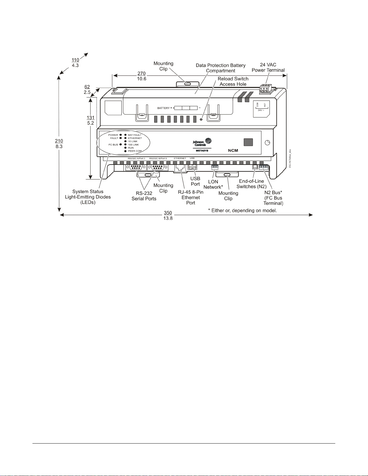
Figure 1: Front of NCM45x0-2 Showing Dimensions (mm/in), Physical Features, and Required Mounting
Space around the NCM (mm/in)
Mounting
Location Considerations
Follow these guidelines when mounting an NCM:
• If the NCM is to replace an existing NCM350 or
NCM361, see Legacy NCM Replacement
Considerations.
• Ensure that the mounting surface can support the
NCM and any user-supplied enclosure.
•
Mount the NCM in proper orientation (Figure 2). A
horizontal mounting orientation is preferred, but the
unit can also be mounted vertically.
• Mount the NCM on an even surface in wall mount
applications whenever possible. If you must mount
the NCM on an uneven surface, be careful not to
crack the mounting clips or NCM housing when
tightening the screws. Use shims or washers to mount
the NCM evenly on the mounting surface.
• Mount the NCM in areas free of corrosive vapors, and
observe the environmental limitations listed in the
Technical Specifications section.
• Allow sufficient space for cable and wire connections
(Figure 1).
• Do not mount the NCM where the ambient
temperature may exceed 50˚C (122˚F).
• Do not mount the NCM on surfaces that are prone to
vibration or in areas where electromagnetic emissions
can interfere with NCM communication.
• Do not obstruct the NCM housing ventilation holes.
• Do not mount the power transformer below the NCM.
For applications where the NCM is mounted inside a
panel or enclosure, follow these additional guidelines:
• Do not install the NCM in an airtight enclosure.
• Do not install heat-generating devices in the enclosure
with the NCM that may cause the ambient
temperature to exceed 50°C (122°F).
Mounting the NCM
Wall Mount Applications
Use the holes in the three mounting clips for wall mount
applications.
To mount the NCM on a wall (or other vertical surface):
1. Ensure that all three mounting clips are inserted into
the back of the NCM housing. Pull the bottom two
clips outward and snap them firmly into the extended
position (Figure 3).
2. Mark the location of the three wall mount holes using
the dimensions in Figure 2, or hold the NCM up to
the wall as a template and mark the locations.
2NCM45x0-2 Series Network Control Module Installation Instructions
Page 3
3. Drill holes in the wall at the locations marked in Step
2 and insert wall anchors (if necessary).
4. Push the bottom mounting clips up to secure the NCM
on the DIN rail tracks.
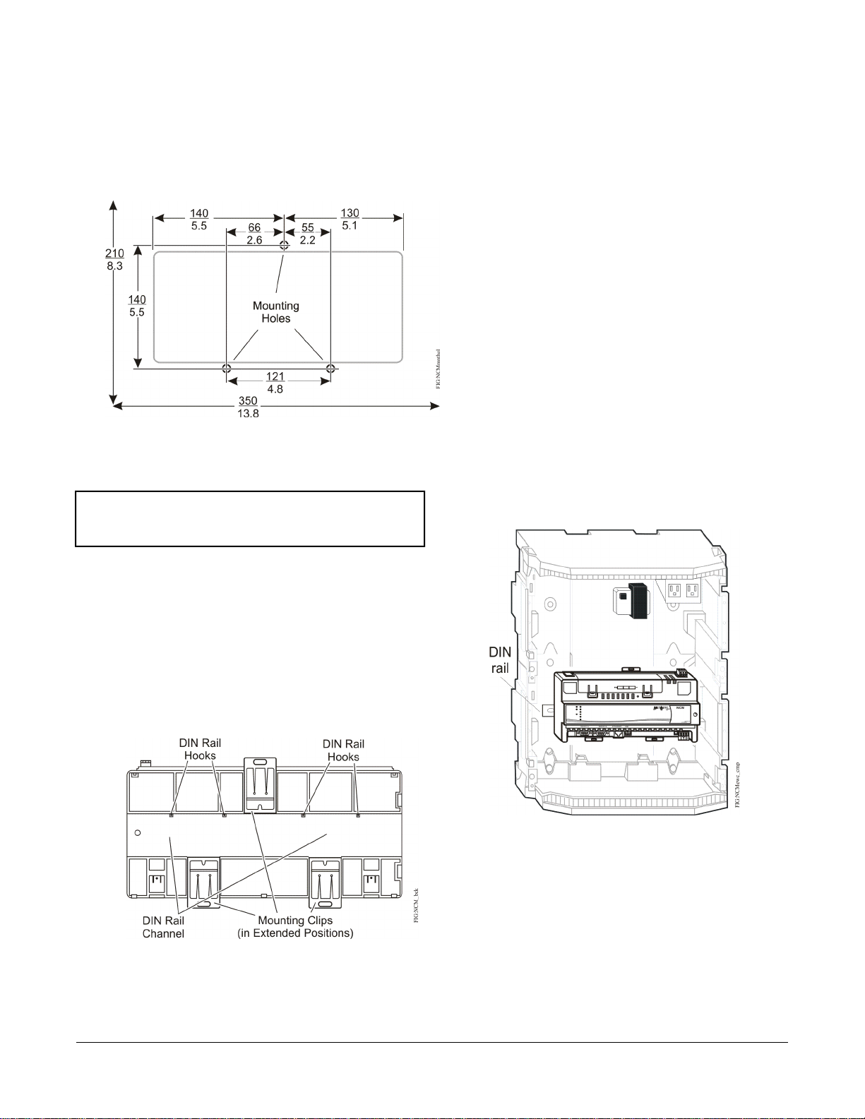
Figure 2: NCM Mounting Screw Hole
Dimensions and Mounting Area Requirements
(mm/in.)
4. Position the NCM and insert the screws through the
holes in the mounting clips, and carefully tighten all
the screws.
Important: Do not overtighten the mounting screws.
Overtightening the screws may damage the
mounting clips or NCM housing.
To remove the NCM from the DIN rail, snap the bottom
DIN clips to the outward extended position, and carefully
lift the NCM off the DIN rail.
Enclosure Mount Applications
Mount the enclosure per the manufacturer’s instructions
and mount the NCM in the enclosure following the
guidelines in the Location Considerations and Mounting
the NCM sections.
Legacy NCM Replacement Considerations
Follow these important guidelines if the NCM is to replace
an existing NCM350/361 controller:
• The unit size and mounting orientation of the
NCM45x0-2 are noticeably different from the
NCM350/361. For example, the NCM45x0-2 is
designed for DIN-rail mounting on the horizontal plane
(Figure 4), but can also be mounted with screws,
either horizontally or vertically. See Mounting the NCM
for details.
Figure 4: Recommended Installation Location of NCM
and Transformer in Standard Enclosure
DIN Rail Mount Applications
To mount the NCM on a DIN rail:
1. Securely mount and center an 8 in. (or longer) section
of DIN rail in the required space.
2. Ensure that the bottom two mounting clips are pulled
outward and snapped firmly into the extended position
(Figure 3).
Figure 3: DIN Rail and Mounting Clip Features
on the Back of the NCM
3. Hang the NCM by the DIN rail hooks (Figure 3) on
the top track of the DIN rail, and position the NCM
DIN rail channel snugly against the tracks of the DIN
rail.
• The wire termination locations on the NCM45x0-2 are
different from the NCM350/361 (Figure 1). Pay close
attention to this when routing wires to their new
locations on the NCM45x0-2.
• The NCM45x0-2 requires 24 VAC power, whereas
the NCM350/361 uses line voltage. See the Wiring
section for steps on installing an appropriate
transformer into the NCM enclosure. Also, the existing
line voltage cable that was used for the NCM350/361
is no longer needed and should be terminated
following local electrician codes.
• The NCM45x0-2 cannot directly replace an:
3NCM45x0-2 Series Network Control Module Installation Instructions
Page 4

NCM100 or NCM200 that is installed in a
baseframe enclosure
- NCM that is an Attached Resource Computer
Network (ARCNET®) node. A Metasys Ethernet
Router may be required if the current network
contains ARCNET nodes only.
- NCM that has two N2 Trunks, because the
NCM45x0-2 supports one N2 Bus
• The N2 Bus termination on the NCM350/361 is
labeled N2 Bus, whereas the N2 Bus termination on
the NCM45x0-2 is called Field Controller (FC) Bus.
Also, the old N2 connector has three terminals,
whereas the connector on the NCM45x0-2 has four
terminals, including a termination for shield. If you
re-use the N2 Bus connector from the old NCM, be
sure to mate the connector toward the correct side of
the FC Bus terminal block. If using N2 Bus wiring that
includes a shield, refer to the N2 Communications
Bus Technical Bulletin (LIT-636018) for additional
information on terminating a shield.
• The LONWORKS® terminal block on the NCM350/361
is not compatible with the LONWORKS network terminal
on the NCM4520-2, so it cannot be reused. Instead,
use the new terminal block provided. LON network
wires are not polarity sensitive.
• For the NCM45x0-2, the Ethernet and LON Network
components are built into the motherboard; separate
network cards are not required.
• The serial ports on the NCM45x0-2 are not labeled
the same as the serial ports on the NCM350/361. Port
3 on the older models is equivalent to the
RS232C A/Port 3 on the NCM45x0-2, and Port 5 is
equivalent to RS232C B/Port 5. A device connected
to Port 3 on the NCM350/361 can be moved to
RS232C A/Port 3 on the NCM450x-2. A device
connected to Port 5 on the NCM350/361 can be
moved to RS232C B/Port 5 on the NCM45x0-2. Serial
Ports 2, 4, and 6 on the NCM350/361 models are not
offered on the NCM45x0-2. If a serial port currently
in use is no longer supported on the new NCM,
database configuration changes are required. Refer
to the NCM45x0-2 Network Control Module
Commissioning Guide (LIT-12011176) for details.
• Serial Ports 2, 4, and 6 on the NCM350/361 models
are not offered on the NCM45x0-2. If a serial port
currently in use is no longer supported on the new
NCM, database configuration changes are required.
Refer to the NCM45x0-2 Network Control Module
Commissioning Guide (LIT-12011176) for details.
• Before removing the NCM350/361, upload its
database to the archive Operator Workstation (OWS)
so that it can be edited later and eventually
downloaded into the new controller. Refer to the
NCM45x0-2 Network Control Module Commissioning
Guide (LIT-12011176) for details.
• While the NCM45x0-2 is restarting, the LEDs on the
unit are not used to indicate its network address or
act as diagnostic indicators of a particular error
condition. The only LEDs that indicate failure are the
Fault and Batt Fault LEDs.
Wiring
Power Supply, Network, and Communication Connections
See Figure 1 for the location of the power supply terminal,
FC or LON terminal, USB port (not used), and Ethernet
port on the NCM.
Power Supply
In North America, the NCM requires a dedicated Class
2, 24 VAC, 25 VA minimum power supply. Outside North
America, use a 24 VAC Safety Extra-Low Voltage (SELV)
transformer at the appropriate rating. The minimum input
voltage for the NCM to operate properly is 20 VAC.
Maximum power consumption is 25 VA.
FC Bus Terminal (NCM4510-2 Only)
The FC Bus network terminal on the NCM4510-2 model
is a 4-position removable, keyed terminal block. Use the
FC Bus terminal to connect field controllers that reside
on the N2 Communications Bus.
See Table 1 and refer to the N2 Communications Bus
Technical Bulletin (LIT-636018) for additional information
and guidelines on wiring devices on an N2 Bus.
LONWORKS Network Terminal
(NCM4520-2 Only)
The LON network terminal on the NCM4520-2 model is
a 3-position removable, keyed terminal block. Use the
LONWORKS port to integrate LON devices into a Metasys
network. The Shield (SHD) connection on the LONWORKS
port is an open terminal and is not connected to the NCM.
Serial Ports
Use the RS232C A/Port 3 and RS232C B/Port 5 serial
ports (Figure 1) for direct connections using a standard
9-pin female to 9-pin female Data Terminal Equipment
(DTE) to DTE null modem cable.
The RS232C A/Port 3 serial port can be used for a variety
of purposes. The supported applications include
configured and unconfigured OWS, printer, modem, or
Operator Terminal (OT).
4NCM45x0-2 Series Network Control Module Installation Instructions
Page 5

Refer to the NCM45x0-2 Network Control Module
Commissioning Guide (LIT-12011176) for information
about these different types of direct and dial-up
connections to the NCM.
The RS232C B/Port 5 serial port can be used for these
applications: configured OWS, printer, modem, OT, or
local Network Terminal (NT). Refer to the NCM45x0-2
Network Control Module Commissioning Guide
(LIT-12011176) for more information about these options.
Mount the NCM securely before wiring the NCM. See the
Mounting section.
Follow these guidelines when wiring an NCM:
• Route the supply power wires and communication
cables at least 50 mm (2 in.) away from the vent slots
on the sides of the NCM housing.
• Provide slack in the wires and cables. Keep cables
routed neatly around the NCM to promote good
ventilation, LED visibility, and ease of service.
USB Port
The USB port is not used. Do not connect any device to
this port.
Ethernet Port
The Ethernet connection (10 or 100 Mb/s) is an 8-pin
RJ-45 network port (Figure 1). Use the Ethernet port to
connect to IP networks. An NCM45x0-2 with a 100 Mb/s
connection communicates properly with older NCMs that
are communicating at 10 Mb/s.
Wiring the NCM
Important: Do not connect 24 VAC supply power to the
NCM before finishing wiring and checking
all wiring connections. Short circuits or
improperly connected wires may result in
permanent damage to the equipment.
Important: Use copper conductors only. Make all wiring
in accordance with local, national, and
regional regulations. The NCM is a
low-voltage (<30 VAC) device. Do not
exceed the NCM electrical ratings.
Important: Do not remove the terminal block keys. The
terminal block plugs and the terminal
sockets are keyed to fit together in the
correct configuration only.
To wire the NCM:
1. Connect the Ethernet communication cable to the
RJ-45, 8-pin Ethernet port shown in Figure 1.
2. For the NCM4510-2, connect the three N2 Bus wires
to the removable 4-terminal plug as shown in Figure
5 (labeled FC Bus). If a shield is present, follow
standard practices for terminating a shield that are
discussed in the N2 Bus literature. Refer to the N2
Communications Bus Technical Bulletin (LIT-636018).
Note: If the NCM is connected to an N2 Bus, you
must set the End-of-Line (EOL) switch to the
proper position. See the Setting the
End-of-Line Switch section in this document.
Figure 5: N2 Bus Wiring
Important: Prevent any static electric discharge to the
NCM. Static electric discharge can damage
the NCM and void any warranties.
Important: Make sure the building automation network
wiring meets the specifications, rules, and
guidelines in the Power Supply, Network,
and Communication Connections section
in this document.
Important: For the NCM4510-2 model, do not remove
the plug that is inserted into the top FC Bus
terminal, or install any connector into this
port. The port is only used if the unit is
migrated to an NAE45 sometime in the
future.
3. For the NCM4520-2, connect the wires from the LON
network trunk to the removable 3-terminal plug as
shown in Figure 6.
5NCM45x0-2 Series Network Control Module Installation Instructions
Page 6

Figure 6: Network Terminal Block and Wiring
Connections
4. If a dial application is required, connect an external
modem to the RS232C port you wish to use.
5. If a direct connect application is required, connect the
appropriate computer cable to the RS232C port you
wish to use.
6. Connect the 24 VAC supply power wires from the
transformer to the removable 3-terminal plug as
shown in Figure 7. The middle terminal is not used.
Figure 7: 24 VAC Supply Power Wiring
Note: Power supply wire colors may be different on
transformers not manufactured by Johnson
Controls®. Follow the transformer manufacturer’s
instructions or the project installation drawings.
Note: When connecting 24 VAC power to the NCMs and
field devices on the network, be consistent so that
transformer phasing is uniform across the devices.
Powering devices with uniform 24 VAC supply
power phasing reduces noise, interference, and
ground loop problems. The NCM does not require
an earth ground connection.
Wiring Considerations and Guidelines for Network Integrations
Table 1: Guidelines for N2 Network Topology
Rules/Maximums AllowedCategory
One N2 trunk per NCMGeneral
Only daisy-chained devices (with maximum stub length of 3 m [10 ft] to any device)
Number of N2 Devices Supported
Cable Wire Type and Size
N2 EOL Terminations
Table 2: Guidelines for LONWORKS Network Bus Topology
Cable Type
Maximum Segment Length with FTT10
Devices Only
100 devices per NCM (60 to 200 TC-9100s) 50 devices per repeater with two
repeaters cascaded
1,500 m (5,000 ft) twisted pair cable without a repeaterCable Length and Type
4,500 m (15,000 ft) twisted pair cable from an NCM and the farthest N2 device
(three segments of 1,500 m [5,000 ft] each, separated by repeaters)
2,000 m (6,600 ft) between two fiber modems
Solid or stranded 18 AWG recommended (24 AWG twisted pair or larger is
acceptable)
Two N2 devices with EOL switches in the ON position, one at each end of each
N2 Bus segment
Maximum Segment Length
1
with FTT10 and/or LPT10
Devices
2,200 m (7,200 ft)2,700 m (8,850 ft)Belden® 85102
2,200 m (7,200 ft)2,700 m (8,850 ft)Belden 8471
1
6NCM45x0-2 Series Network Control Module Installation Instructions
Page 7

Table 2: Guidelines for LONWORKS Network Bus Topology
Cable Type
1 For the bus topology, the maximum length stub cable is 3 m (10 ft), and the stub lengths must be calculated into the overall
segment length.
Maximum Segment Length with FTT10
Devices Only
1
Maximum Segment Length
with FTT10 and/or LPT10
Devices
1,150 m (3,770 ft)1,400 m (4,600 ft)Level IV 22 AWG
750 m (2,460 ft)900 m (2,950 ft)JY (St.) Y 2 x 2 x 0.8
1
Table 3: Guidelines for LONWORKS Network Free Topology
Maximum Node-to-Node DistanceCable Type
Maximum Segment Length
with FTT10 and/or LPT10
Devices
500 m (1,640 ft)500 m (1,640 ft)Belden 85102
500 m (1,640 ft)500 m (1,640 ft)Belden 8471
500 m (1,640 ft)400 m (1,300 ft)Level IV 22
500 m (1,640 ft)320 m (1,050 ft)JY (St.) Y 2 x 2 x 0.8
Table 4: Maximum Number of Devices per LONWORKS Network Segment
Maximum AllowedDevice Type
64 (if repeaters are not used)Free Topology Transceiver (FTT)-10 Nodes Only
128 (if repeaters are used)FTT-10 Nodes Only
[(FTT10 x 2) + LPT10] < 128Mixed FTT-10 and LPT-10 Nodes
Terminators:
2 bus type EOL terminators required (NU-EOL202-0)Bus Topology
1 free topology terminator required (NU-EOL203-0)Free Topology
Maximum of 1 per segmentPhysical Layer Repeaters
1 Each LPT10 channel segment (between repeaters) requires its own power supply. Other factors such as power consumption
of individual LPT10 devices may limit a segment to fewer devices. The NCM does not have an internal network terminator.
Table 5: NCM Ethernet Network Rules
Category
Number of Devices
Line Length and Type
1
Refer to the N1 Ethernet/IP Network Technical Bulletin (LIT-6360175) for recommended parts and part numbers.
Setup and Adjustments
Rules/Maximums Allowed
Point-to-point star topology with network hubs/switchesGeneral
Maximum of 100 supervisory devices may be connected to one
site
2,000 m (6,600 ft) for plastic/glass fiber optic with external
adapter
100 m (330 ft) CAT5 cable
For 10/100BaseT, no line terminators allowedTerminations
The 24 VAC supply power to the NCM charges the data
1
protection battery. At initial startup, the battery may
Data Protection Battery
The NCM is shipped with the data protection battery
installed and connected. Do not disconnect the battery
for any reason other than to replace a defective battery.
require a charging period of at least 4 hours before it
supports data protection if power fails. Up to three
consecutive, back-to-back power failures can occur before
a full 15-hour recharging period is required.
7NCM45x0-2 Series Network Control Module Installation Instructions
Page 8

The data protection battery slowly loses charge when 24
VAC power is removed from the NCM. If the battery
completely loses charge, the NCM real-time clock stops.
The database and code, however, are still retained. (This
is different from the NCM300 Series model, in which only
72 hours of backup was provided, after which the unit
required a download.)
Whenever an NCM is disconnected from 24 VAC power
for over 30 days, ensure that the unit has the correct date
and time. Also, keep the NCM powered long enough to
recharge the data protection battery.
Setting the End-of-Line Switch
Network and field devices at either end of the N2 Bus
must be set as network terminated devices. The NCM
has an EOL switch that allows you to set the NAE as a
network terminated device. The NCM is shipped with the
EOL switch in the factory default, ON (up) position (Figure
8). Set the EOL switch to the appropriate position for each
NCM in your network. For more details, refer to the
Setting Terminations section of the N2 Communications
Bus Technical Bulletin (LIT-636018).
Figure 8: FC Bus EOL Switch in the Factory Default
ON (Up) Position
Important: Do not disconnect the battery while the unit
is shutting down, or the data being saved
may be corrupted.
Important: The data protection battery must be installed
and charged before disconnecting the 24
VAC supply power.
Troubleshooting
LED Status Indicators
The NCM has nine LEDs to indicate power and network
communication status. Figure 9 shows the LEDs and
describes the LED indications. For the NCM4510-2 model,
the FC Bus LED indicates network traffic over the N2
Bus. For the NCM4520-2 model, the LON LED indicates
network traffic over the LON Network. All the other LEDs
are the same on both models.
Figure 9: NCM LED Designations
Turning On the NCM
Apply 24 VAC power to the NCM and verify that the RUN
LED begins to flash. This indicates normal operation. If
this is a new NCM from the factory, the RUN LED
continues to flash, indicating that the unit needs to be
commissioned with WNCSETUP. Refer to the NCM45x0-2
Network Control Module Commissioning Guide
(LIT-12011176) for additional information on
commissioning an NCM.
Disconnecting Power from the NCM
When 24 VAC supply power to an NCM is disconnected
or lost, the NCM is non-operational, but the POWER LED
(Figure 9) remains On and the data protection battery
continues to power the NCM for a few minutes while
volatile data is backed up in nonvolatile memory. The
RUN LED flashes during this process. When complete,
all LEDs go Off.
LED Test Sequence at Startup
When you connect power to the NCM, it initiates a
2-second LED test to verify the operational status of its
LEDs. After this test, the operating system is loaded, the
NCM application starts, the NCM database is loaded from
flash memory (or, if not present, downloaded from the
OWS), and NCM initialization occurs. A steady On RUN
LED indicates a fully initialized NCM. If the RUN LED
continues to blink for several minutes, verify whether the
NCM database was successfully downloaded from the
archive Operator Workstation. You can also examine the
Network Controller (NC) Task Error Log, which may
provide useful information for diagnosing startup
problems. For details, refer to the NCM45x0-2 Network
Control Module Commissioning Guide (LIT-12011176).
For more information about the other possible behaviors
of the NCM LEDs, see Table 6.
8NCM45x0-2 Series Network Control Module Installation Instructions
Page 9

Table 6: NCM LED Designations, Normal Status, and Descriptions
Descriptions/Other ConditionsNormal StatusLED Designation
On SteadyPOWER (Green)
BlinkETHERNET (Green)
BlinkFC BUS (Green) or LON BUS
(Green)
On SteadyRUN (Green)
Off SteadyBATT FAULT (Red)
On Steady = Unit is getting power from either the battery or 24 VAC
power.
Off Steady = Unit is shut down.
Blink = Data is transferring on the Ethernet connection. Ethernet traffic
is general traffic (may not be for the NCM).
Off Steady = No Ethernet traffic, probably indicates a dead Ethernet
network or bad Ethernet connection.
On Steady = Ethernet connection is established at 10 Mbps.On Steady10/LINK (Green)
On Steady = Ethernet connection is established at 100 Mbps.On Steady100/LINK (Green)
Blink = Normal communications; the N2/LON Bus is transmitting and
receiving data. Blinks are generally in sync with data transmission,
but should not be used to indicate specific transmission times.
Off Steady = No field controllers are defined to N2/LON Bus in the
NCM.
None. PEER COM is On only during startup.Off SteadyPEER COM (Green)
On Steady = NCM software is fully initialized.
On 1 second, Off 1 second = NCM software is starting up, or
controller is waiting to be commissioned and/or requires a data
download.
On 0.5 seconds, Off 0.5 seconds = NCM software is shutting down.
On Steady = Battery defective. Blink = Data Protection Battery is not
installed. Memory cannot be backed up. Connect or install battery.
On Momentarily, then Off = Internal fault has occurred.Off SteadyFAULT (Red)
Repair Information
If you replace an NCM on a site with a new NCM for any
reason or add a new NCM to a site, you must update the
system database to ensure that the new NCM is
recognized and able to communicate with the site.
Table 7: NCM45x0-2 Ordering Information
DescriptionProduct Code Number
MS-NCM45x0-2 (Base features of each
NCM45x0)
MS-NCM4510-2
MS-NCM4520-2
Requires a 24 VAC power supply. Each model includes two RS-232-C serial
ports, one USB serial port (unused), one Ethernet port, and an MS-BAT1020-0
Data Protection Battery.
Supports one N2 trunk (RS-485 port). Up to 100 devices (60 to 200 TC-9100s)
are supported on the N2 trunk when a repeater is used.
Includes a LONWORKS port and supports one LONWORKS trunk. Up to 127 devices
are supported on the LONWORKS port.
Buy American equivalent to MS-NCM4510-2MS-NCM4510-2G
Buy American equivalent to MS-NCM4520-2MS-NCM4520-2G
Repair for MS-NCM4510-2MS-NCM4510-702
Repair for MS-NCM4520-2MS-NCM4520-702
Refer to the NCM45x0-2 Network Control Module
Commissioning Guide (LIT-12011176) for information on
removing an NCM from service and configuring a
replacement NCM.
Note: Batteries removed from this device must be
recycled or disposed of in accordance with local,
national, and regional regulations. Only certified
technicians or qualified building maintenance
personnel should service Johnson Controls
products.
9NCM45x0-2 Series Network Control Module Installation Instructions
Page 10

Table 8: NCM45x0-2 Accessories Ordering Information
DescriptionProduct Code Number
MS-BAT1020-0
Y65T31-0
MS-NC45NTE-0
Replacement data protection battery: Rechargeable NiMH 3.6 VDC, 500 mAh
battery with a typical life of 5 to 7 years at 21°C (70°F) (Higher operating
temperatures reduce battery life.)
Power transformer family (Class 2, 24 VAC, 40 VA maximum output), no
enclosure
Power transformer (Class 2, 24 VAC, 50 VA maximum output), no enclosureAS-XFR050-0
NCM4500 NT Cable Kit (North American version)MS-NC45NTK-0
NCM4500 NT Cable Kit (International version). Power adapter has removable
plug that can use one of the several different power plugs included in the kit.
Technical Specifications
Table 9: NCM45x0-2 Model
Power Requirement
Data Protection Battery
Memory
Network and Serial Interfaces
Dimensions (Height x Width x Depth)
Dedicated nominal 24 VAC, Class 2 power supply (North America), SEL Vpower supply
(Europe), at 50/60 Hz (20 VAC minimum to 30 VAC maximum)
25 VAC maximumPower Consumption
0 to 50°C (32 to 122°F)Ambient Operating Temperature
10 to 90% RH, 30°C (86°F) maximum dew pointAmbient Operating Conditions
-40 to 70°C (-40 to 158°F)Ambient Storage Temperature
5 to 95% RH, 30°C (86°F) maximum dew pointAmbient Storage Conditions
Supports data protection on power failure. Rechargeable NiMH battery: 3.6 VDC 500
mAh, with a typical life of 5 to 7 years at 21°C (70°F); Product Code Number:
MS-BAT1020-0
192 MHz Renesas® SH4 7760 RISC processorProcessor
128 MB Flash nonvolatile memory
128 MB Synchronous Dynamic Random Access Memory (SDRAM)
Note: Even though the unit has 128 MB of memory, it is sized to emulate the capacity
of an NCM300 Series controller with 10 MB of memory.
Microsoft® Windows® CE embeddedOperating System
One Ethernet port; 10/100 Mb/s; 8-pin RJ-45 connector
One optically isolated RS-485 port; 9600 bps; pluggable and keyed 4-position terminal
block (FC Bus available on NCM4510-2 model only)
One LONWORKS port; FTT10 78 Kbps; pluggable, keyed 3-position terminal block
(LONWORKS port available on NCM4520-2 model only)
Two RS232C serial ports with standard 9-pin sub-D connectors that support standard
baud rates.
One USB serial port with standard USB connector (not used)
131 x 270 x 62 mm (5.2 x 10.6 x 2.5 in.)
Minimum space for mounting: 210 x 350 x 110 mm (8.3 x 13.8 x 4.3 in.)
Plastic housing material: ABS + polycarbonate; Protection: IP20 (IEC60529)Housing
On flat surface with screws on three mounting clips or a single 35 mm DIN railMounting
10NCM45x0-2 Series Network Control Module Installation Instructions
Page 11

Table 9: NCM45x0-2 Model
1.2 kg (2.7 lb)Shipping Weight
Compliance
The performance specifications are nominal and conform to acceptable industry standard. For application at conditions beyond
the specifications, consult the local Johnson Controls office. Johnson Controls, Inc. shall not be liable for damages resulting
from misapplication or misuse of its products.
United States: Underwriters Laboratories Inc. (UL) Listed (PAZX), UL 916, FCC
compliant, CFR47, Part 15, Class B
Canada: UL Listed (PAZX7), CAN/CSA C22.2 No. 205, Industry Canada compliant
Europe: CE Mark - Johnson Controls, Inc., declares that this product is in compliance
with the essential requirements and other relevant provisions of the EMC Directive
2004/108/EC.
Australia/New Zealand: C-Tick mark compliant
Building Efficiency
507 E. Michigan Street, Milwaukee, WI 53202
Metasys® and Johnson Controls® are registered trademarks of Johnson Controls, Inc.
All other marks herein are the marks of their respective owners. © 2013 Johnson Controls, Inc.
www.johnsoncontrols.comPublished in U.S.A.
11NCM45x0-2 Series Network Control Module Installation Instructions
 Loading...