

Page 1
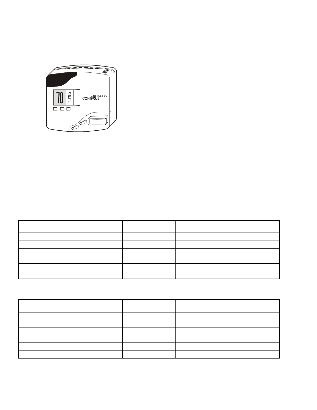
Installation Instructions MRC
Modular Room Control (MRC) Series
Digital Thermostat
Issue Date August 14, 2002
Application
The MRC Digital Thermostat is an expandable
multi-purpose, high-quality Direct Digital Control (DDC)
illuminated thermostat designed to control virtually any
Fan Coil Unit (FCU) or Packaged Terminal Air
Conditioning (PTAC) found in hotel guestrooms. The
MRC comes standard with five relays and can be
equipped with an on-board Infrared (IR) transceiver
and Passive Infrared (PIR) motion detector. Coupled
with a magnetic door switch (wired or wireless), the
MRC becomes the brain of a highly effective Energy
Management System (EMS) for guestrooms.
When connected to the Central Interface Network
(CINET) with a pair of low voltage wires, a centrally
controlled EMS package is created. The MRC is
readily expandable to include functionality such as
humidity control, outside temperature display, mini-bar
access reporting, occupancy reporting to
housekeeping, automatic control of lights, and much
more. Use of infrared or low-voltage wiring enables
remote control of lights, occupancy reporting, and
other functions.
Installation
Locate the MRC thermostat as follows:
Mounting
The MRC is designed to be mounted on a standard
double-gang (4 x 4) junction box. If it is necessary to
mount the MRC on a single-gang box, the left side
(display side) of the MRC overlaps the wall area to the
left of the junction box.
To mount the MRC mounting plate:
1. Remove the two small screws at the base of the
MRC.
2. Pull the bottom of the back-mounting plate slightly
away from the front housing and then pull the
back-mounting plate down.
IMPORTANT: If the back-mounting plate is rotated
more than 2 or 3°, the plastic tabs at the top of the
plate may fracture or break off.
3. Attach the mounting plate to the junction box,
using the mounting screws provided with the
MRC. Ensure that the plate is mounted with the
raised arrow pointing UP (↑).
Wiring
• on a partitioning interior wall, and approximately
1.5 m (5 ft) above the floor in a location of average
temperature
• away from direct sunlight or radiant heat, outside
walls or behind doors, air discharge grills,
stairwells, or outside doors
• away from steam or water pipes, warm air stacks,
unheated/uncooled areas, or sources of electrical
interference
!
CAUTION: Risk of Shock.
Disconnect the power supply before mounting the
thermostat to prevent electrical shock or possible
damage to the equipment.
2002 Johnson Controls, Inc.
©
Part No. 24-9778-6, Rev. – www.johnsoncontrols.com
!
CAUTION: Risk of Equipment Damage.
Before applying power, make all wiring connections
and check the connections. Short-circuited or
improperly connected wires may result in permanent
damage to the unit.
IMPORTANT: Make all wiring connections in
accordance with the National Electrical Code (NEC)
and all local regulations.
To simplify installing and removing the MRC, a
standard Molex® 10-position or 8-position connector is
used. The female receptacle is on the back of the
MRC vertically centered over the high-voltage section
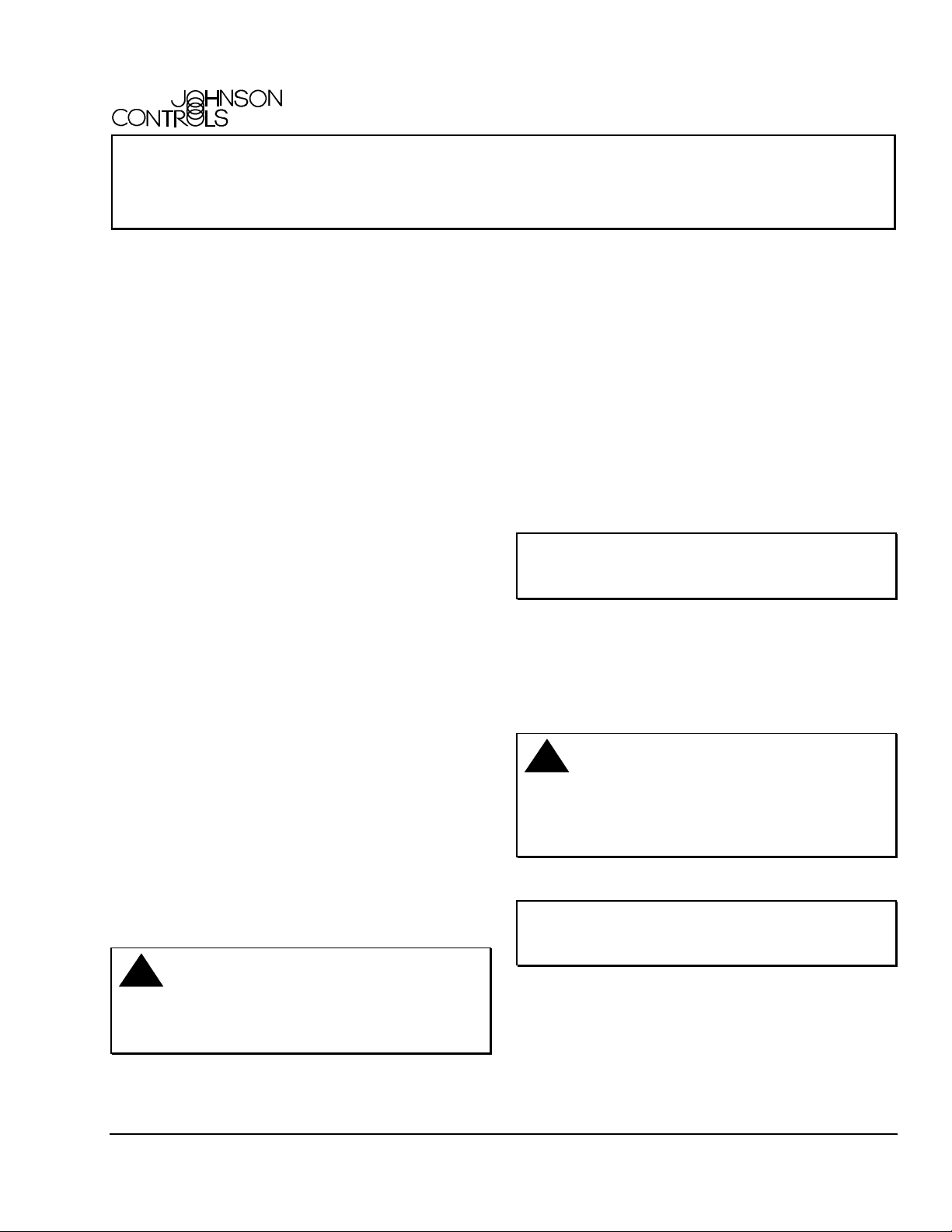
(see Figure 1).
1
Page 2
Molex
Receptacle
Figure 1: Molex Receptacle Location
The MRC is supplied with a Molex connector prewired
with eight or ten 8 in. (203 mm) color-coded leads.
These leads are connected in the wall junction box to
the wiring from the FCU or other Heating, Ventilating,
and Air Conditioning (HVAC) device with wire nuts
(see Figure 2).
Note: For installations in which all 10 leads are not
required, the extraneous leads should be cut off at the
Molex connector.
UP
Figure 4 shows the 8-position Molex connector. It is
used with the 24 V TRIAC model MRC and comes with
8-in. wire leads. The end view of the male connector
from the wire insertion side with the pin numbers is
indicated. This is the same as looking at the female
connector point on the backside of the MRC.
12 34
6
8.7
220
5
8
7
Figure 4: 8-Pin Molex Connector Wire Lead,
in. (mm)
IMPORTANT: It is essential that the leads from
the FCU or other HVAC device be properly
connected to the male 8-pin or 10-pin connector
(see Figure 6 through Figure 10). Following each
wiring diagram is a table containing the color legend
for the 8-pin or 10-pin female receptacle (H1) at the
back of the MRC. Common industry practice for
color coding has been used, but there is no
guarantee that the same standard has been used for
the wires coming from the FCU.
Network
Harness
Molex
Connector
Figure 2: Backplate Wiring
Figure 3 shows the 10-position Molex connector with
8 in. (203 mm) wire leads, supplied with all relay
output models of the thermostat. The end view of the
male connector from the wire insertion side with the
pin numbers is indicated. This is the same as looking
at the female connector point on the backside of
the MRC.
234
8.7
220
1
6
7
89
5
10
To wire the MRC thermostat:
1. Use wire nuts to connect the wiring harness to the
FCU wires within the electrical box (see Figure 2).
2. Plug the prewired 8 or 10-pin connector into the
female receptacle at the back of the MRC.
3. Hook the tabs at the top rear of the MRC housing
into the matching depressions at the top of the
mounting plate and rotate the bottom of the
housing toward the wall until it snaps into place on
the mounting plate (see Figure 5).
4. Secure the housing to the mounting plate with the
two small screws removed in Step 1 of the
Mounting section.
Figure 3: 10-Pin Molex Connector Wire Lead,
in. (mm)
Figure 5: Returning the MRC to the Mounting Plate
2 Modular Room Control (MRC) Series Digital Thermostat Installation Instructions
Page 3
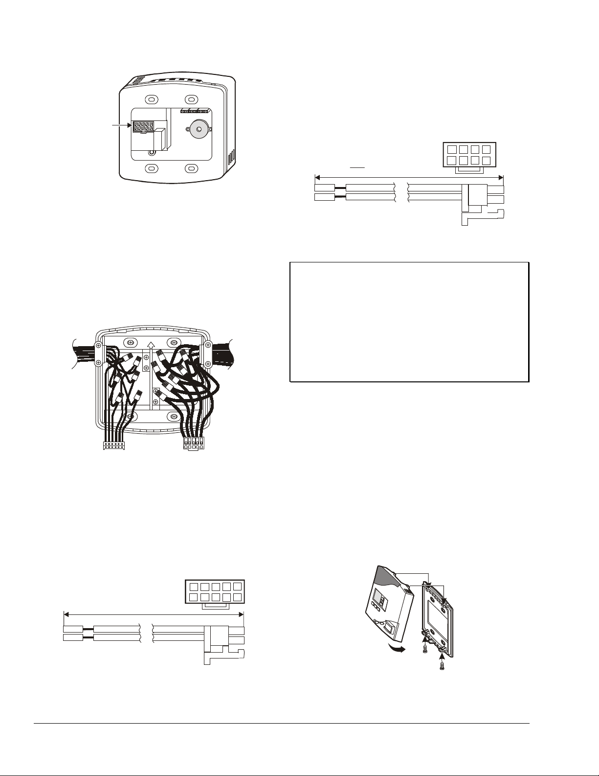
Phase
Transformer
Neutral
Heat Valve
Cool Valve
Heat
Cool
H
M
L
Med
Low
Fan Motor
Relay
Fan Coil Unit
Pack
Note: In this application, the valves and fan motor
operate with the same line voltage. Therefore,
grey (valve power) and violet (fan power) wires
are connected to the red (control power) wire with a
wire nut.
Note: This drawing only reflects connections
between the FCU/PTAC and the MRC Stat.
It does not include the door switch, Network,
or other connections.
24 VAC
MRC
O
B
B
G
r
r
l
r
a
o
a
e
n
w
c
e
g
k
n
n
e
(
(
3
(
5
(
1
)
1
)
)
0
)
1 2 3 4 5
6 7 8 9 10
6
5
43
2
1
Y
B
G
W
R
V
e
l
u
l
l
e
o
w
(
4
(
)
6
)
e
i
r
h
o
e
d
i
l
y
t
e
e
(
t
2
(
8
(
(
)
7
9
)
)
)
H1
7
1098
Logic and Relays
Figure 6: 4-Pipe, 3-Speed Fan FCU with 7 Wires 24 VAC Wiring
Table 1: Pin Number Wire Color and Function
Pin Number Wire Color Function
1
2
3
4
5
6
7
8
9
10
Green Ground
Red Control Power
Black Neutral
Blue High Fan
Brown Medium Fan
Yellow Cold Water Valve
White Hot Water Valve
Grey Valve Power
Violet Fan Power
Orange Low Fan
Modular Room Control (MRC) Series Digital Thermostat Installation Instructions 3
Page 4
Phase
Heat Valve
Cool Valve
H
M
L
Fan Motor
Fan Coil Unit
Note: In this application, the valves and fan motor
operate with the same line voltage. Therefore,
grey (valve power) and violet (fan power) wires
are connected to the black (control power) wire with a
wire nut.
Note: This drawing only reflects connections
between the FCU/PTAC and the MRC Stat.
It does not include the door switch, Network,
or other connections.
MRC
GREEN(1)
BLUE(10)
WHITE(3)
1 2 3 4 5
6 7 8 9
5
43
2
1
ORANGE( 5)
YELLOW(4)
7
6
VIOLET (9)
RED(6)
BLACK(2)
BROWN( 7)
GREY(8)
H1
10
1098
Figure 7: 4-Pipe, 3-Speed Fan FCU with 7 Wires 100 VAC - 277 VAC Wiring
Table 2: Pin Number Wire Color and Function
Pin Number Wire Color Function
1
2
3
4
5
6
7
8
9
10
Green Ground
Black Control Power
White Neutral
Yellow High Fan
Orange Medium Fan
Red Cold Water Valve
Brown Hot Water Valve
Grey Valve Power
Violet Fan Power
Blue Low Fan
4 Modular Room Control (MRC) Series Digital Thermostat Installation Instructions
Logic and Relays
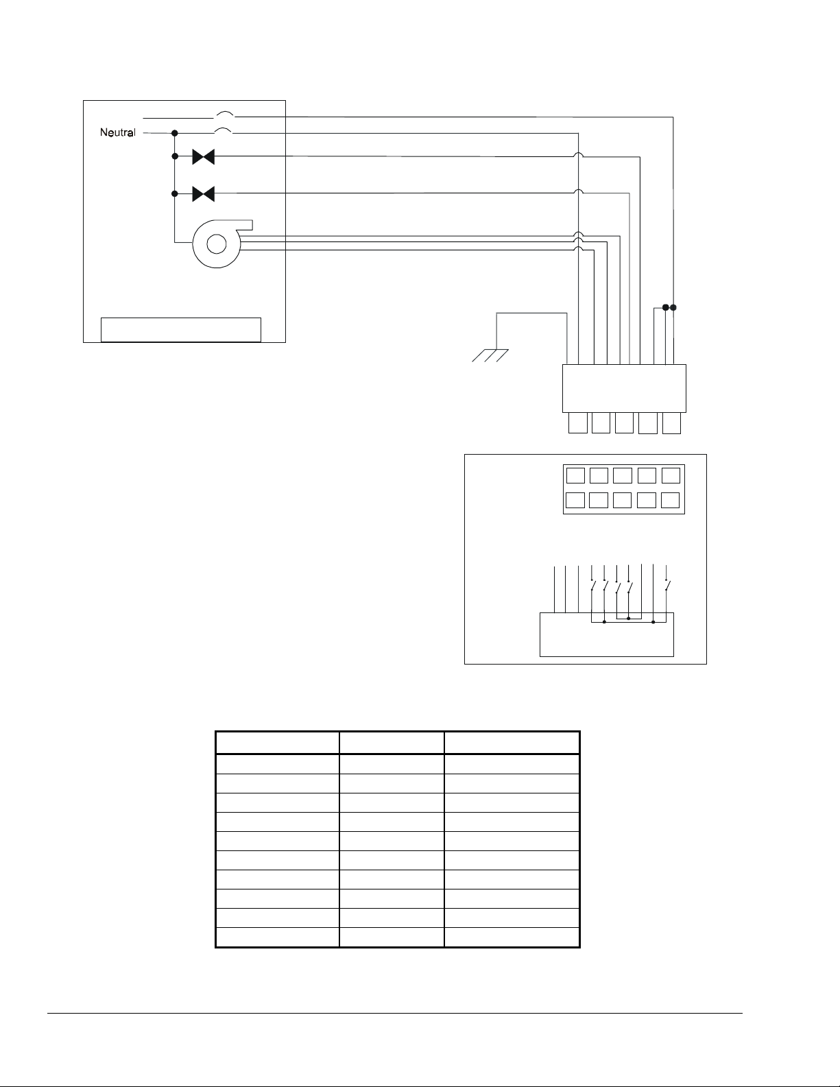
Page 5

Phase
Neutral
Heat Valve
Cool Valve
H
L
Fan Motor
Fan Coil Unit
ORANGE(5)
GREEN(1)
BLUE(10)
YELLOW (4)
7
6
5
Note: In this application, the valves and fan motor
operate with the same line voltage. Therefore,
grey (valve power) and violet (fan power) wires
are connected to the black (control power) wire with a
wire nut.
Note: This drawing only reflects connections
between the FCU/PTAC and the MRC Stat.
It does not include the door switch, Network,
or other connections.
MRC
WHITE( 3)
1 2 3 4 5
6 7 8 9
43
2
1
Logic and Relays
Figure 8: 4-Pipe, 2-Speed Fan FCU with 6 Wires 100 VAC - 277 VAC Wiring
Table 3: Pin Number Wire Color and Function
Pin
Wire Color Function
Number
1
2
3
4
5
6
7
8
9
10
Green Ground
Black Control Power
White Neutral
Yellow High Fan
Orange Medium Fan
Red Cold Water Valve
Brown Hot Water Valve
Grey Valve Power
Violet Fan Power
Blue Low Fan
VIOLET(9)
RED(6)
BLACK(2)
GREY(8)
BROWN(7)
H1
10
1098
Modular Room Control (MRC) Series Digital Thermostat Installation Instructions 5
Page 6

Phase
Neutral
Fan Coil Unit
Heat Strip
Cool Valve
Fan Motor
Note: In this application, the valves, heat strip, and
fan motor operate with the same line voltage.
Therefore, grey (valve and heat strip power) and
violet (fan power) wires are connected to the
black (control power) wire with a wire nut.
Note: This drawing only reflects connections
between the FCU/PTAC and the MRC Stat.
It does not include the door switch, Network,
or other connections.
Relay
H
M
L
MRC
GREEN(1)
WHITE( 3)
BLUE(10)
1 2 3 4 5
6 7 8 9 10
5
43
2
1
BROWN(7)
ORANGE(5)
6
GREY(8)
VIOLET(9)
RED(6)
YELLOW(4)
7
8
BLACK(2)
H1
109
Figure 9: 2-Pipe, 3-Speed Fan FCU with Heat Strip and 7 Wires 100 VAC - 277 VAC Wiring
Table 4: Pin Number Wire Color and Function
Pin Number Wire Color Function
1
2
3
4
5
6
7
8
9
10
Green Ground
Black Control Power
White Neutral
Yellow High Fan
Orange Medium Fan
Red Cold Water Valve
Brown Hot Water Valve
Grey Valve Power
Violet Fan Power
Blue Low Fan
6 Modular Room Control (MRC) Series Digital Thermostat Installation Instructions
Logic and Relays
Page 7

Phase
Neutral
Transformer
Heat Valve
Cool Valve
24 VAC
Fan Coil Unit
H
M
L
Fan Motor
ORANGE(5)
BROWN(7)
BLUE(10)
YELLOW(4)
GREEN(1)
WHITE(3)
VIOLET(9)
RED(6)
BLACK(2)
GREY(8)
Note: In this application, the fan motor operates
at line voltage, the control and valves operate at
24 VAC. Therefore, grey (valve power) wire is
connected to the black (control power) wire with
a wire nut.
Note: This drawing only reflects connections
between the FCU/PTAC and the MRC Stat.
It does not include the door switch, Network,
or other connections.
MRC
1 2 3 4 5
6 7 8 9 10
6
5
43
2
1
Logic and Relays
H1
7
1098
Figure 10: 4-Pipe, 3-Speed Fan FCU with 7 Wires 100 VAC - 277 VAC Fan Wiring, and 24 VAC Control and
Valve Wiring
Table 5: Pin Number Wire Color and Function
Pin Number Wire Color Function
1
2
3
4
5
6
7
8
9
10
Green Ground
Black Control Power
White Neutral
Yellow High Fan
Orange Medium Fan
Red Cold Water Valve
Brown Hot Water Valve
Grey Valve Power
Violet Fan Power
Blue Low Fan
Modular Room Control (MRC) Series Digital Thermostat Installation Instructions 7
Page 8

Setup and Adjustments
The MRC coupled with a magnetic door switch (wired
or wireless) and a Passive Infrared (PIR) sensor
(on-board or separate [wall mount or ceiling mount])
becomes the brain of a highly effective energy
management system for guestrooms.
Door Switch - Wired (MRC19-MDS0)
In each room, run a two-conductor, 24-gage
[minimum] cable from the thermostat to the doorframe
location (see Figure 11) extending through the door
header framing leaving a minimum of 5 in. (127 mm) of
extra cable. The cable should extend through the
center of the framing approximately 5 in. (127 mm ) in
from the top (or side) corner of the door.
Run the other end of the cable [along with any other
low-voltage cables] to the back of the MRC thermostat.
A minimum of 12 in. (305 mm) of extra cable should be
left at the thermostat location for termination.
IMPORTANT: New Construction.
At the time of doorframe installation, the cable must
be pulled through a pre-drilled hole in the hollow
metal door header. This allows for installation of the
door switch at a later date. (The door must also be
pre-drilled to accept the magnet side of the door
switch.)
Note: The MRC19-MDS0 has a lip that protrudes
below the frame of the door. The spacing between the
door and the frame must be able to accommodate this
lip (which is about 0.060 in. [1.5 mm] thick).
The switch and the mating magnet may also be
installed horizontally near the top, as shown in the
drawing as an alternate location. For installation in a
wooden door/frame, the depth of the hole in the frame
should be 2 in. (51 mm) and the depth of the hole in
the door should be 1 in. (25.4 mm).
Clearance
4 to 6 in.
102 to 152 mm
Alternate
Location
Hole
Diameter
0.75 in.
19 mm
(Door and Frame)
0.10 in. (2.54 mm) Minimum
0.50 in. (12.7 mm) Maximum
Note: If an MRC19-PKG0 DND/MUR external plate
is being used, the cable from the MRC19-MDS can be
terminated at the location of the MRC19-PKG0. A
minimum of 12 in. (305 mm) of extra cable should be
left at the MRC19-PKG0 location for connection to the
MRC19-PKG0. This method of installation eliminates
the need to run the cable directly to the MRC
Thermostat. Refer to the Do-Not-Disturb/Make-Up-
Room/Door Chime Kit Installation Instructions
(Part No. 24-9778-22) for more detailed installation
and wiring instructions.
The MRC19-MDS0 is a normally open reed magnet
switch. Electrically, the contacts are closed when the
reed switch is in close proximity to a suitable magnet.
Figure 11 defines the recommended mounting method
for the switch in a hotel guestroom environment. The
location of the contact was selected so that the switch
detects a door that is resting against the frame but is
not latched. Placing the switch closer to the hinge of
the door provides a door closed indication with
increasingly open angle.
Figure 11: MRC19-MDS0 Installation
Door Switch - Wireless (MRC19-MDS2)
In each room, run the supplied two-conductor, 24-gage
cable from the doorframe location (see Figure 12)
extending through the door header framing leaving a
minimum of 12 in. (305 mm) of extra cable. The cable
is to extend through the center of the framing
approximately 5 in. (127 mm) in from the top (or side)
corner of the door or where otherwise specified.
The cable should be run from the door header location
to the specified location of the MRC19-MDS2 or MDS3
infrared transmitter. The transmitter is typically
mounted above or to the side of the doorframe casing.
A minimum of 12 in. (305 mm) of extra cable should
protrude from the wall for connection to the infrared
transmitter.
8 Modular Room Control (MRC) Series Digital Thermostat Installation Instructions
Page 9

IMPORTANT: New Construction.
At the time of doorframe installation, the cable must
be pulled through a pre-drilled hole in the hollow
metal door header. This allows for installation of the
door switch at a later date. (The door must also be
pre-drilled to accept the magnet side of the door
switch.)
Clearance
4 to 6 in.
102 to 152 mm
Alternate
Location
(Door and Frame)
0.10 in. (2.54 mm) Minimum
0.50 in. (12.7 mm) Maximum
Note: The sensor is corner mounted and does not
cover the cable if it is more than 3/4 in. (19 mm) out of
the corner. Determine the specific location of the
motion detector by establishing where the optimal
coverage of the room occurs. The owner, project
architect, and/or interior designer must review and
approve the location.
Four-conductor 24-gage cable from
PIR Motion
Detector
PIR to Thermostat
FCU Cable
CINET Connection
to Floor Bridge
Hole
Diameter
0.75 in.
19 mm
Figure 12: MRC19-MDS2 Installation
Motion Detector (PIR) Non-integrated in
Thermostat
Note: Refer to the Modular Room Control
MRC19-PIR Series Motion Detector Sensors
Installation Instructions (Part No. 24-9778-49) for
more detailed installation and wiring instructions.
Wall Mount
In each room where a non-integrated motion
detector is required, run a four-conductor, 24-gage
cable from the location of the motion detector (typically
the corner of the room), along with any other
low-voltage cables directly to the MRC
thermostat (see
Figure 13). Leave a minimum of 12 in. (305 mm) of
extra cable at the thermostat for connections.
F/C
OFF/AUTOFANDISPLAY
MAKE UP
ROOM
DO NOT DISTURB
MRC
Thermostat
Figure 13: MRC19-PIRW Motion Sensor Installation
Ceiling Mount
Mount the detector on a firm section of ceiling at a
height of between 8 and 15 feet (2.44 and 4.57 m) and
well away from neon or fluorescent lights.
Run a four-conductor, 24-gage cable from the location
of the motion detector (along with any other
low-voltage cables) to the MRC thermostat. Leave a
minimum of 12 in. (305 mm) of extra cable at the
thermostat for connections.
One end of the cable should extend directly out of the
corner, 1-1/2 in. (38 mm) below the bottom of the
crown molding (refer to architectural plans for crown
molding dimensions). A minimum of 12 in. (305 mm) of
extra cable should extend beyond the finished wall
surface.
Modular Room Control (MRC) Series Digital Thermostat Installation Instructions 9
Page 10
Operation
The following descriptions are the display and control
button functionality for the standard MRC product:
F/C
OFF/AUTO FAN DISPLAY
MAKE UP
ROOM
DO NO T DISTU RB
Figure 14: Liquid Crystal Display (LCD) and
Control Buttons
• The OFF/AUTO button cycles the MRC between
OFF and AUTO modes. In AUTO mode, the MRC
automatically determines the optimum valve and
fan speed settings needed to maintain target (SET
temperature). In the OFF mode, only the word
OFF is displayed and the MRC is no longer in
control of the fan speed or valve settings except
for maintaining room temperature between
programmed maximum and minimum limits.
• The FAN button is only functional when the MRC
is in AUTO mode. If pressed, the display first
shows the current fan speed. If pressed again, fan
speed cycles to the next higher speed, and that
speed is displayed. After HI fan speed is reached,
if the button is pressed again, fan speed cycles
back to LO, and the sequence begins again. The
MRC automatically adjusts valve settings in an
attempt to maintain target temperature. After
10 minutes, operation reverts to full AUTO in
which the MRC sets the fan to the speed best
suited to maintain target temperature.
• The DISPLAY button cycles between SET (target)
temperature and ROOM (actual) temperature.
When the MRC is activated and in AUTO mode,
the SET temperature is automatically displayed.
The ROOM temperature is only displayed if the
DISPLAY button is pressed and then is displayed
for only 5 seconds. Following that 5-second
period, the display reverts to SET temperature.
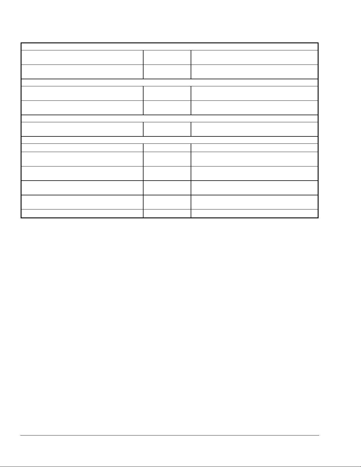
Table 6 through Table 9 are four typical scenarios
showing the automatic operation of the MRC under
various temperature conditions.
Table 6: 2-Pipe, 3 Speed Fan FCU with Cold Water in Pipe
System State
(OFF/AUTO)
OFF
AUTO
AUTO
AUTO
AUTO
AUTO
Room Temperature Set Temperature Fan Valve
75° 72°
72° 72°
73° 72°
75° 72°
77° 72°
70° 72°
OFF CLOSED
OFF CLOSED
LO OPEN
MED OPEN
HI OPEN
OFF CLOSED
Table 7: 2-Pipe, 3 Speed Fan FCU with Cold Water in Pipe and Continuous Fan Specified
System State
(OFF/AUTO)
OFF
AUTO
AUTO
AUTO
AUTO
AUTO
Room Temperature Set Temperature Fan Valve
75° 72°
72° 72°
73° 72°
75° 72°
77° 72°
70° 72°
LO CLOSED
LO CLOSED
LO OPEN
MED OPEN
HI OPEN
LO CLOSED
10 Modular Room Control (MRC) Series Digital Thermostat Installation Instructions
Page 11

Table 8: 4-Pipe, 3 Speed Fan FCU with Hot and Cold Water Available
System State
(OFF/AUTO)
OFF
AUTO
AUTO
AUTO
AUTO
AUTO
AUTO
Room
Temperature
75° 72°
72° 72°
73° 72°
75° 72°
77° 72°
70° 72°
67° 72°
Set
Temperature
Fan
OFF CLOSED CLOSED
OFF CLOSED CLOSED
LO OPEN CLOSED
MED OPEN CLOSED
HI OPEN CLOSED
LO CLOSED OPEN
HI CLOSED OPEN
Table 9: 2-Pipe, 2 Speed Fan FCU with Cold Water in Pipe, Heat Strip
and Continuous Fan Specified
System State
(OFF/AUTO)
OFF
AUTO
AUTO
AUTO
AUTO
AUTO
AUTO
Room
Temperature
75° 72°
72° 72°
73° 72°
75° 72°
77° 72°
70° 72°
67° 72°
Set
Temperature
Fan Valve
LO CLOSED OFF
LO CLOSED OFF
LO OPEN OFF
HI OPEN OFF
HI OPEN OFF
LO CLOSED ON
HI CLOSED ON
Cold Water
Valve
Hot Water
Valve
Heat Strip
Valve
Table 10: Accessories
Description Part Number Corresponding Literature
5 Triac Expansion Board
6 Relay Expansion Board
5 Triac/2 AO Expansion Board
6 Relay/2 AO Expansion Board
IR Lamp Module - Non-Dimming
IR Wall Switch - Non-Dimming
Continued on next page . . .
Expansion Boards
MRC19-EXP1 –
MRC19-EXP2 –
MRC19-EXP3 –
MRC19-EXP4 –
Lamp and Lighting Control Devices
MRC19-LMP0
MRC19-LMP1
MRC Series Digital Thermostat Product Bulletin
MRC Series Digital Thermostat Product Bulletin
(LIT-1201430)
(LIT-1201430)
Modular Room Control (MRC) Series Digital Thermostat Installation Instructions 11
Page 12
Passive IR Detector, Wall Mounted
Passive IR Detector, Ceiling Mounted
Smart IR Eye to Communicate with Locks,
Wall Mounted
Smart IR Eye to Communicate with Locks,
Ceiling Mounted
Do-Not-Disturb/Make-Up-Room/Door Chime
Packaged Set of DND/MUR/Chime Including
Wiring Harnesses
Oversized Adapter Plate 6.25” x 6.25”
Magnetic Door Switch, Wired, Core Mount
Magnetic Door Switch, Wired, Surface Mount
IR Transmitter w/ MRC-6MDS-0 (white)
IR Transmitter w/ MRC-6MDS-0 (black)
Remote IR Transceiver for Extender Cards
Motion Detectors (Cont.)
MRC19-PIRW
MRC19-PIRC
MRC Series Motion Detector Sensors Installation
Instructions (Part No. 24-9778-49)
MRC Series Motion Detector Sensors Installation
Instructions (Part No. 24-9778-49)
IR Eyes
MRC19-SIRW –
MRC19-SIRC –
MRC19-PKG0
DND/MUR/Door Chime Kit Installation Instructions
Peripherals
MRC19-PLT0 –
MRC19-MDS0
MRC19-MDS1
MRC19-MDS2
MRC19-MDS3
MRC19-EYE0 –
MRC Series Digital Thermostat Product Bulletin
MRC Series Digital Thermostat Product Bulletin
MRC Series Digital Thermostat Product Bulletin
MRC Series Digital Thermostat Product Bulletin
(Part No. 24-9778-22)
(LIT-1201430)
(LIT-1201430)
(LIT-1201430)
(LIT-1201430)
12 Modular Room Control (MRC) Series Digital Thermostat Installation Instructions
Page 13

Technical Specifications
Product
Power Requirements
Relay Contact Rating
Triac Relay Contact Rating
Recommended Wire Size
Thermostat Measurement
Range
Outdoor Air Temperature
Indication Range
Display Resolution
Minimum Deadband
°C/°F Conversion
Ambient Operating
Conditions
Ambient Storage
Conditions
Dimensions (H x W x D)
Shipping Weight
FCC Compliance
MRC Series Digital Thermostat
24 VAC at 50/60 Hz, 24 VDC nominal, 2.4 VA (MRC19-3xxxx and MRC19-4xxxx)
100 to 240 VAC at 50/60 Hz, 2.4 VA (MRC19-5xxxx)
265 to 277 VAC at 50/60 Hz, 2.4 VA (MRC19-6xxxx)
240 VAC, 2 ampere maximum
50 mA minimum, 250 mA maximum
18 gauge
33 to 99°F (1 to 37°C)
0 to 99°F (-18 to 37°C)
Setpoint: one decimal point; Actual Temperature: zero decimal point for °F and one decimal
point for °C
2°F (1°C) between heating and cooling
Button located on front display
41 to 149°F (5 to 65°C), 0-95% RH noncondensing
33 to 149°F (1 to 65°C)
4.7 x 4.7 x 1.2 in. (120 x 120 x 30 mm)
0.6 lb (0.27 kg)
This equipment has been tested and found to comply with the limits for a Class B digital
device, pursuant to Part 15 of the FCC Rules. These limits are designed to provide
reasonable protection against harmful interference when the equipment is operated in a
commercial environment. This equipment generates, uses, and can radiate radio frequency
energy and, if not installed and used in accordance with the instruction manual, may cause
harmful interference to radio communications. Operation of this equipment in a residential
area is likely to cause harmful interference, in which case the user will be required to
correct the interference at his own expense.
The performance specifications are nominal and conform to acceptable industry standards. For application at conditions beyond these
specifications, consult the local Johnson Controls office. Johnson Controls, Inc. shall not be liable for damages resulting from misapplication or
misuse of its products.
Controls Group
507 E. Michigan Street
P.O. Box 423 Published in U.S.A.
Milwaukee, WI 53201 www.johnsoncontrols.com
Modular Room Control (MRC) Series Digital Thermostat Installation Instructions 13
 Loading...