

Page 1
STANDARD PSC
INSTALLATION MANUAL
ISO 9001
Certified Quality
Management System
!
!
MODULAR MULTI-POSITION
AIR HANDLERS
MODELS: MP SERIES
LIST OF SECTIONS
GENERAL . . . . . . . . . . . . . . . . . . . . . . . . . . . . . . . . . . . . . . . . . . . . . .1
SAFETY . . . . . . . . . . . . . . . . . . . . . . . . . . . . . . . . . . . . . . . . . . . . . . . .1
UNIT INSTALLATION . . . . . . . . . . . . . . . . . . . . . . . . . . . . . . . . . . . . .2
DUCT WORK AND CONNECTIONS . . . . . . . . . . . . . . . . . . . . . . . . . 5
ELECTRIC HEATER INSTALLATION . . . . . . . . . . . . . . . . . . . . . . . .6
LINE POWER CONNECTIONS . . . . . . . . . . . . . . . . . . . . . . . . . . . . . .7
LOW VOLTAGE CONTROL CONNECTIONS . . . . . . . . . . . . . . . . . .8
LIST OF FIGURES
Return Duct Attachment . . . . . . . . . . . . . . . . . . . . . . . . . . . . . . . . . . . .2
Typical Installation . . . . . . . . . . . . . . . . . . . . . . . . . . . . . . . . . . . . . . . .3
Coil and Air Handler Attachment Details . . . . . . . . . . . . . . . . . . . . . . .3
Gasket Location . . . . . . . . . . . . . . . . . . . . . . . . . . . . . . . . . . . . . . . . . .4
Dimensions & Duct Connection Dimensions . . . . . . . . . . . . . . . . . . . .4
Typical Horizontal Installation . . . . . . . . . . . . . . . . . . . . . . . . . . . . . . .5
Duct Attachment . . . . . . . . . . . . . . . . . . . . . . . . . . . . . . . . . . . . . . . . . .6
LIST OF TABLES
Dimensions . . . . . . . . . . . . . . . . . . . . . . . . . . . . . . . . . . . . . . . . . . . . .4
Physical and Electrical Data - Cooling Only . . . . . . . . . . . . . . . . . . . . .8
Electrical Data - Cooling Only . . . . . . . . . . . . . . . . . . . . . . . . . . . . . . . .8
Electrical Heat: Minimum Fan Speed . . . . . . . . . . . . . . . . . . . . . . . . . .9
KW & MBH Conversions - For Total Power Input Requirement . . . . . 9
BLOWER SPEED CONNECTIONS . . . . . . . . . . . . . . . . . . . . . . . . . . 8
UNIT DATA . . . . . . . . . . . . . . . . . . . . . . . . . . . . . . . . . . . . . . . . . . . . 8
MAINTENANCE . . . . . . . . . . . . . . . . . . . . . . . . . . . . . . . . . . . . . . . . 14
AIR SYSTEM ADJUSTMENT . . . . . . . . . . . . . . . . . . . . . . . . . . . . . . 14
WIRING DIAGRAM . . . . . . . . . . . . . . . . . . . . . . . . . . . . . . . . . . . . . 15
TYPICAL THERMOSTAT CONNECTIONS . . . . . . . . . . . . . . . . . . . 16
START UP SHEET . . . . . . . . . . . . . . . . . . . . . . . . . . . . . . . . . . . . . . 17
Duct Work Transition. . . . . . . . . . . . . . . . . . . . . . . . . . . . . . . . . . . . . . 6
Blower Delay Control Board . . . . . . . . . . . . . . . . . . . . . . . . . . . . . . . . 6
Line Power Connections . . . . . . . . . . . . . . . . . . . . . . . . . . . . . . . . . . . 7
Blower Speed Connections . . . . . . . . . . . . . . . . . . . . . . . . . . . . . . . . 8
Duct Static Measurements. . . . . . . . . . . . . . . . . . . . . . . . . . . . . . . . . 14
Wiring Diagram - PSC - Single Phase Heat Kits . . . . . . . . . . . . . . . 15
Typical Wiring Diagram - PSC . . . . . . . . . . . . . . . . . . . . . . . . . . . . . 16
Electric Heat Performance Data: 208/230-1-60 . . . . . . . . . . . . . . . . . 9
Electrical Data For Single Source Power Supply: 208V-230V-1-60 . 10
Electrical Data For Multi-Source Power Supply: 208V-230V-1-60 . . 11
Air Flow Data (CFM) . . . . . . . . . . . . . . . . . . . . . . . . . . . . . . . . . . . . . 12
SECTION I: GENERAL
The MP modular air handler series provides the flexibility for installation
in any position. This unit may be used for upflow, downflow, horizontal
right, or horizontal left applications.
These units may be located in a closet, utility room, attic, crawl space,
or basement. These versatile models may be used for cooling or heat
pump operation with or without electric heat or indoor coil.
Top or side power and control wiring, color coded leads for control
wiring, and electric heaters all combine to make the installation easy
and minimize installation cost.
Electric heat kits are available as field installed accessories. Single
phase kits are available from 2.5 kW to 20 kW.
SECTION II: SAFETY
This is a safety alert symbol. When you see this symbol on
labels or in manuals, be alert to the potential for personal
injury.
Understand and pay particular attention to the signal words DANGER,
WARNING, or CAUTION.
DANGER indicates an imminently hazardous situation, which, if not
avoided, will result in death or serious injury
WARNING indicates a potentially hazardous situation, which, if not
avoided, could result in death or serious injury
CAUTION indicates a potentially hazardous situation, which, if not
avoided may result in minor or moderate injury.
alert against unsafe practices and hazards involving only property
damage.
.
.
It is also used to
WARNING
FIRE OR ELECTRICAL HAZARD
Failure to follow the safety warnings exactly could result in serious
injury, death or property damage. A fire or electrical hazard may result
causing property damage, personal injury or loss of life.
WARNING
The air handler area must not be used as a broom closet or for any other
storage purposes, as a fire hazard may be created. Never store items
such as the following on, near or in contact with the furnace.
1. Spray or aerosol cans, rags, brooms, dust mops, vacuum cleaners or other cleaning tools.
2. Soap powders, bleaches, waxes or other Cleaning compounds;
plastic items or containers; gasoline, kerosene, cigarette li ghter
fluid, dry cleaning fluids or other volatile fluid.
3. Paint thinners and other pain ting compounds.
4. Paper bags, boxes or other paper products
Never operate the air handler with the blower door removed. To do so
could result in serious personal injury and/or equipment damage.
1190828-UIM-G-0915
Page 2
1190828-UIM-G-0915
!!!
SIDE VIEW
RETURN AIR
DUCT
A0398-001
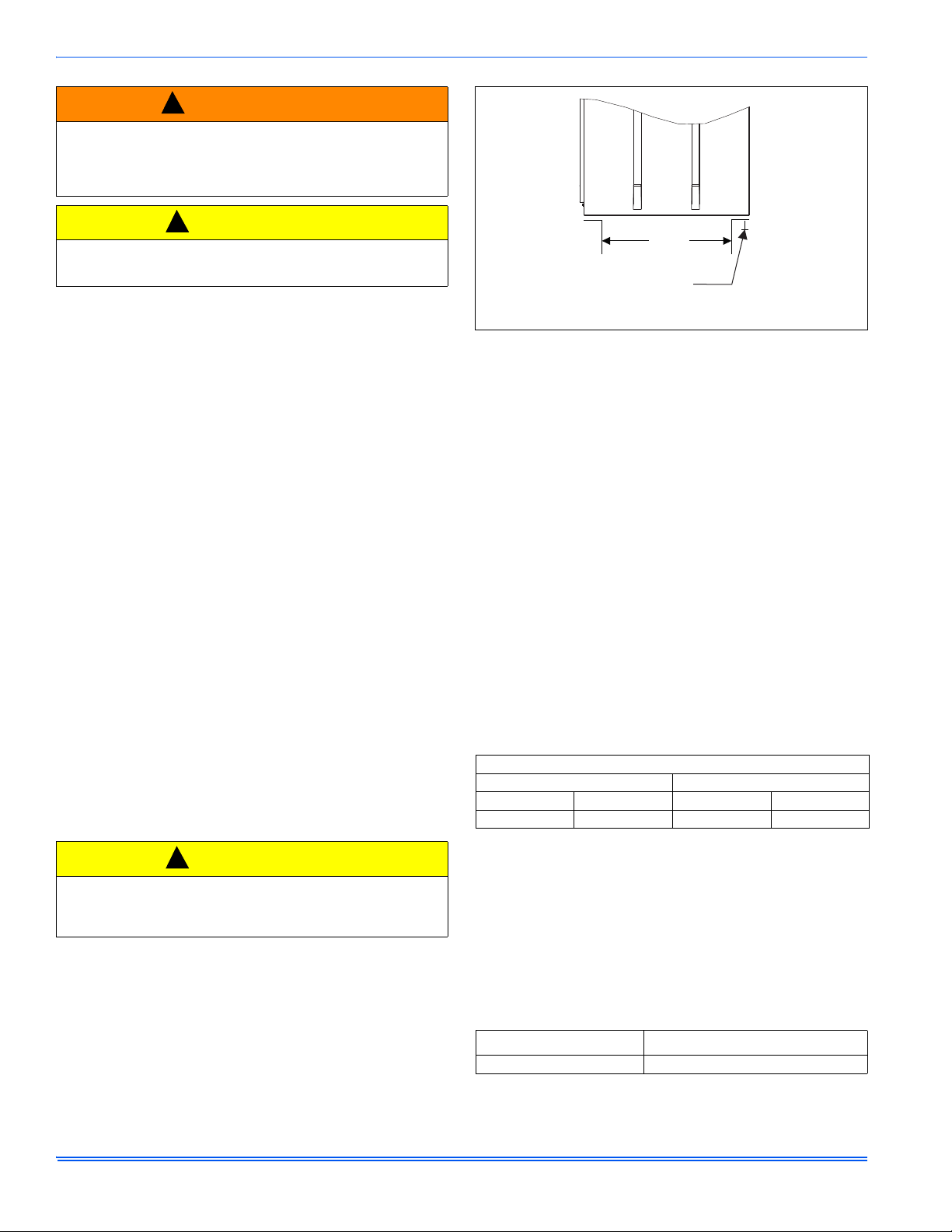
When attaching duct work with
screws - keep screws within 5/8”
of sides and back of air handler.
WARNING
Improper installation, adjustment, alteration, or maintenance may create a condition where the operation of the product could cause personal injury or property damage. Refer to this manual for assistance,
or for additional information, consult a qualified contractor, installer, or
service agency.
CAUTION
This product must be installed in strict compliance with the installation
instructions and any applicable local, state, and national codes
including, but not limited to building, electrical, and mechanical codes.
SAFETY REQUIREMENTS
1. Failure to carefully read and follow all instructions in this manual
can result in air handler malfunction, death, personal injury and/or
property damage.
2. This air handler should be installed in accordance with all national
and local building/safety codes and requirements, local plumbing or
wastewater codes, and other applicable codes.
3. This air handler should be installed only in a location and position
specified in the “Unit Installation” section of this Instruction Manual.
4. The air handler is not to be used for temporary heating of buildings
or structures under construction.
5. Always install the air handler to operate within the air handler’s
intended maximum outlet air temperature.
6. The unit rating plate displays the air handler model number. The
unit dimensions for the supply air plenum are provided in Figure 5
and Table 1 of this Instruction Manual. The plenum must be
installed according to the instructions. The return air duct attachment is shown in Figure 1.
7. Clearance from combustible material is provided under “Clearances” in the “Unit Installation” section.
8. It is necessary to maintain clearances for servicing. Access must be
allowed for electric heaters and blower.
9. The unit rating plate and power supply must be verified to ensure
that the electrical characteristics match.
10. Air handler shall be installed so the electrical components are protected from water.
11. Installing and servicing heating/cooling equipment can be hazardous due to the electrical components. Only trained and licensed
personnel should install, repair, or service heating/cooling equipment. Unlicensed service personnel can perform basic maintenance functions such as cleaning and replacing the air filters. When
working on heating/cooling equipment, the precautions in the manuals and on the labels attached to the unit and other safety precautions must be observed as applicable.
CAUTION
These air handlers should be transported & handled in an upright,
upflow position. Failure to do so may result in unit damage and personal injury. Configuration conversions should be done at site of
installation.
12. These instructions cover minimum requirements and conform to
existing national standards and safety codes. In some instances
these instructions exceed certain local codes and ordinances,
especially those who have not kept up with changing residential
and non-HUD modular home construction practices. These instructions are required as a minimum for a safe installation.
FIGURE 1: Return Air Duct Attachment
INSPECTION
As soon as a unit is received, it should be inspected for possible damage during transit. If damage is evident, the extent of the damage
should be noted on the carrier’s freight bill. A separate request for
inspection by the carrier’s agent should be made in writing. Also, before
installation the unit should be checked for screws or bolts, which may
have loosened in transit. There are no shipping or spacer brackets
which need to be removed.
It should be verified that the appropriate coil and accessories (such as
heater kit and thermostatic expansion valve kit) are available as
required. Installation of these accessories or field conversion of the unit
should be accomplished before setting the unit in place or connecting
any wiring, duct work or piping.
SECTION III: UNIT INSTALLATION
UNIT SIZING
1. The size of the unit should be based on an acceptable heat loss or
gain calculation for the structure. The ACCA – Manual J or other
approved methods may be used. Reference Figure 5 and Table 1.
2. Only connect the air handler to a duct system which has an external
static pressure within the allowable range.
3. Airflow must be within the minimum and maximum limits approved
for electric heat, indoor coils and outdoor units.
Entering Air Temperature Limits
Wet Bulb Temp.°F Dry Bulb Temp. °F
Min. Max. Min. Max.
57 72 65 95
4. When an air handler is installed so that supply ducts carry air circulated by the air handler to areas outside the space containing the air
handler, the return air shall also be handled by duct(s) sealed to the
air handler casing and terminating in the space to be cooled/
heated.
5. Refer to the unit rating plate for the air handler model number, and
then see the dimensions page of this instruction for supply air plenum dimensions. The plenum must be installed according to the
instructions.
6. The installer must check available supply power and verify that it is
within the normal operating voltage range for the unit. The acceptable voltage range for these units is as follows:
Air Handler Voltage
208-230-1-60 187-253
1. Rated in accordance with ARI Standard 110, utilization range “A”.
Normal Operating
1
Voltage Range
2 Johnson Controls Unitary Products
Page 3
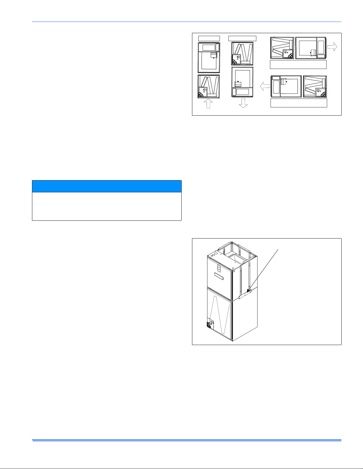
CLEARANCES
A0346-001
UPFLOW
DOWNFLOW
HORIZONTAL RIGHT
HEAT
HORIZONTAL LEFT
HEAT
HEAT
HEAT
HEAT
A0347-001
OUTER TIE PLATE (3 PLACES)
AIR
HANDLER
COIL
NOTE:
External tie plates
are installed on both
sides and the back
Clearances must be taken into consideration, and provided for as
follows:
1. Maintenance and servicing access - minimum 36” from front of unit
recommended for blower motor / coil replacement.
2. The duct work connected to this unit is designed for zero clearance
to combustible materials.
3. A combustible floor base accessory is available for downflow applications of this unit, if required by local code.
LOCATION
Location is usually predetermined. Check with owner’s or dealer’s
installation plans. If location has not been decided, consider the
following in choosing a suitable location:
1. Select a location with adequate structural support, space for service
access, and clearance for air return and supply duct connections.
2. Using hanging brackets to wall mount this single piece air handler
unit is not recommended.
3. Normal operating sound levels may be objectionable if the air handler is placed directly over some rooms such as bedrooms, study,
etc.
4. If using the air handler unit with an indoor coil, select a location that
will permit installation of condensate line to open drain or outdoors
allowing condensate to drain away from structure.
NOTICE
The primary and secondary drain line must be trapped to allow proper
drainage of condensate water. The secondary drain line should be
piped to a location that will give the occupant a visual warning that the
primary drain is clogged. If the secondary drain line is not used, it
must be capped.
5. When an indoor coil is installed in an attic or above a finished ceiling, an auxiliary drain pan should be provided under the air handler
as is specified by most local building codes.
6. Proper electrical supply must be available.
7. If unit is located in an area of high humidity (i.e. an unconditioned
garage or attic), nuisance sweating of casing may occur. On these
installations, unit duct connections and other openings should be
properly sealed, and a wrap of 2” fiberglass insulation with vinyl
vapor barrier should be used.
1190828-UIM-G-0915
FIGURE 2: Typical Installation
AIR HANDLER AND COIL UPFLOW, DOWNFLOW,
AND HORIZONTAL POSTIONS
1. Apply neoprene gasket to the return air end of air handler.
2. Attach three tie plates to external sides and back of air handler
casing using screws. Refer to Figure 3.
3. Position blower casing over appropriate coil opening (depending
on configuration). Refer to Figure 2.
4. Attach the three tie plates to coil casing using screws. Refer to Figure 3.
5. Remove coil access panel.
6. Slide the coil out of the coil cabinet, and set coil to the side.
7. Locate 2” wide foam gasket.
8. Apply foam gasket over the air handler and coil mating seams on
the interior of both unit sides and back. Refer to Figure 4.
9. Slide the coil into the housing, and install the coil access panel.
AIR HANDLER CONFIGURATION
These air handler units are supplied ready to be installed in an upflow,
downflow, horizontal right or horizontal left position. Refer to Figure 2.
The unit requires no conversion procedures.
FIGURE 3: Coil and Air Handler Attachment Details
Johnson Controls Unitary Products 3
Page 4
1190828-UIM-G-0915
FOAM GASKET
AIR HANDLER
E
F
A
A0327-001
SERVICE DISCONNECT
PANEL
TOP OUTLET
DIMENSIONS
BOTTOM INLET
DIMENSIONS
C
D
12-3/16”
19-1/8”
B
20-1/2”
21-1/2”
FIGURE 4: Gasket Location
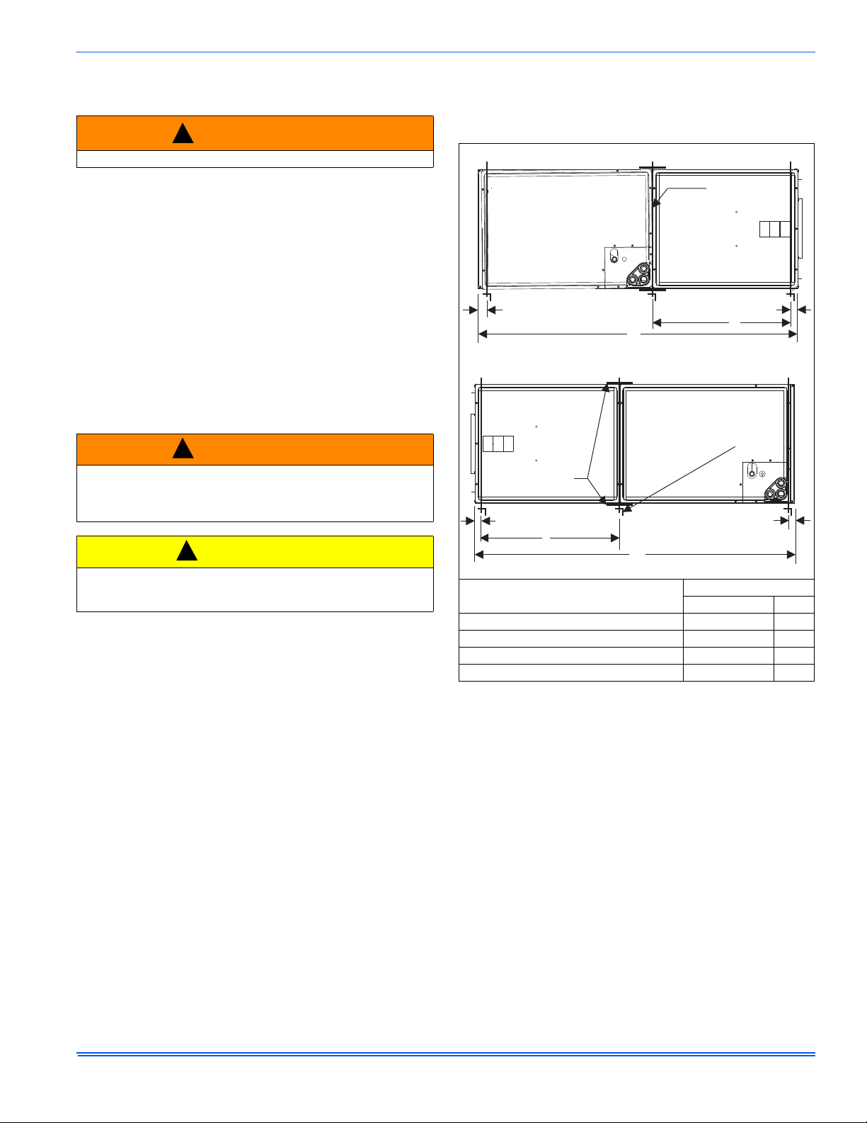
FIGURE 5: Dimensions & Duct Connection Dimensions
MP
1
ABCDEF
TABLE 1:
Dimensions
MODELS
Height Width Bottom Opening Top Opening Power Control
08B 21-1/2 17-1/2 16-1/2 16-1/2
12B 21-1/2 17-1/2 16-1/2 16-1/2
14D 22-1/2 24-1/2 23-1/2 23-1/2
16C 22-1/2 21 20 20
20D 22-1/2 24-1/2 23-1/2 23-1/2
1. All dimensions are in inches.
2. Actual size (Conduit size).
Dimensions
Wiring Knockouts
2
7/8 (1/2)
1-3/8 (1)
7/8 (1/2)
1-23/32 (1-1/4)
4 Johnson Controls Unitary Products
Page 5
1190828-UIM-G-0915
!
!
!
SUSPENSION SUPPORT LOCAT IONS FOR HORIZONTAL RIGHT
2”
1-1/2”
MIN. 1-1/2” x 1-1/2”
Angle Recommended
length 26” minimum
with 2” clearance on both
sides of Air Handler
MIN. 3/8”
THREADED ROD
H
1”
1-1/2”
A0348-002
X
H
SUSPENSION SUPPORT LOCAT IONS FOR HORIZONTAL LEFT
X
TIE PLATE
SECTION IV: DUCT WORK AND
CONNECTIONS
WARNING
Use only 1/2” screws to connect duct work to bottom of unit.
Air supply and return may be handled in one of several ways best
suited to the installation. Upflow, horizontal or downflow applications
may be used.
The vast majority of problems encountered with heating and cooling
systems can be linked to improperly designed or installed duct systems.
It is therefore highly important to the success of an installation that the
duct system be properly designed and installed.
When installing a central air return grille in or near the living space, it is
advisable to design the duct work so that the grille is not in direct line
with the opening in the unit. One or two elbows and acoustical duct liner
assures a quieter system. Operation where return air duct is short or
where sound may be a problem, acoustical duct liner should be used
inside the duct. If electric heat is used, non-flammable material must be
used.
Use flexible duct connectors to minimize the transmission of vibration/
noise into the conditioned space. Never fasten duct work directly to the
structure.
WARNING
Do not bring in return air from a location which could introduce hazardous substances into the airflow.
Use 1/2” screws to connect duct work to cabinet. If pilot holes are
drilled, drill only through field duct and unit flange.
HORIZONTAL SUSPENSION
For suspension of these units in horizontal applications, it is recommended to use angle steel support brackets with threaded rods, supporting the units from the bottom, at the locations shown in Figure 6.
CAUTION
This unit is not designed for non-ducted (freeblow) applications. Do
not operate without duct work attached to unit.
Equipment should never be operated without filters.
Insulation of duct work is a must where it runs through an unheated
space during the heating season or through an uncooled space during
the cooling season. The use of a vapor barrier is recommended to
prevent absorption of moisture from the surrounding air into the
insulation.
The supply air duct should be properly sized by use of a transition to
match unit opening. All ducts should be suspended using flexible
hangers and never fastened directly to the structure.
Duct work should be fabricated and installed in accordance with local
and/or national codes. This includes the standards of the National Fire
Protection Association for Installation of Air-Conditioning and
Ventilating Systems, NFPA No. 90B. Duct systems should be designed
in accordance with the Air Conditioning Contractors of America (ACCA)
– Manual D.
(Cabinet Width) Position
(17-1/2”) Horizontal Left 40-1/2” – 47-1/2” 20”
(21” thru 24-1/2”) Horizontal Left 43-1/2” – 55-1/2” 21”
(17-1/2”) Horizontal Right 40-1/2” – 47-1/2” 20”
(21” thru 24-1/2”) Horizontal Right 43-1/2” – 55-1/2” 21”
FIGURE 6: Typical Horizontal Installation
Dimensions
HX
Johnson Controls Unitary Products 5
Page 6
1190828-UIM-G-0915
A0445-001
DUCT FLANGES
(Shipped in bag with unit)
A0332-001
RECOMMENDED
TRANSITION
SUGGESTED LOCATI ON
OF BLOCK OFF PLATE
!
!
PSC CONTROLBOARD
A0356-001
DUCT FLANGES
Three duct flanges are provided to assist in positioning and attaching
duct work to the air handler. These flanges are included in the unit parts
bag. With the screws from the parts bag, install one of the duct flanges.
Duct flanges have holes on both legs with one leg longer than the other.
The longer leg can be used to mate against the air handler so that
different thicknesses of duct board can be made flush with the outer
surface of the air handler. Repeat the procedure for the other two
flanges. Refer to Figure 7. If the flanges are not used, they may be
discarded.
FIGURE 7: Duct Attachment
CAUTION
Use 1/2” screws to connect duct work to unit. Longer screws will
pierce the drain pan and cause leakage. If pilot holes are drilled, drill
only though field duct and unit bottom duct flange.
Duct work that is not designed to match the supply air opening can
cause turbulence inside the plenum. This turbulence can change the air
flow patterns across the electric heater limit switches. If the factory
suggested transition cannot be fabricated, it is recommended that a
block off plate (approximately 8" high and running the full width of the
plenum) be attached to the supply opening. Refer to Figure 8 as a
visual aid. The use of this block off plate will enable better air circulation
across the limit switches.
AIR FILTERS
Return air filters are required and must be field supplied. Filtration must
be accomplished external to the unit.
.
CAUTION
Equipment should never be operated without filters.
SECTION V: ELECTRIC HEATER
INSTALLATION
If the air handler requires electric heat, install the electric heat kit
according to the installation instructions included with the kit. After
installing the kit, mark the air handler nameplate to designate the heater
kit that was installed. If no heater is installed, mark the name plate
appropriately to indicate that no heat kit is installed.
Use only 6HK Revision C or later heater kits, as listed on air handler
name plate and in these instructions. Use data from Tables 4 through 9
for information on required minimum motor speed tap to be used for
heating operation, maximum over-current protection device required as
listed for combination of air handler and heater kit.
FIGURE 8: Duct Work Transition
UNIT CONNECTIONS
There are several ways to handle the supply and return air duct
connections. The location and sizing of the connections depends on the
situation and the method best suited to the installation. Upflow,
horizontal or downflow applications may be used.
The supply air duct should be properly sized by use of a transition to
match unit opening. Refer to Table 1 for air handler unit inlet and outlet
dimensions.
FIGURE 9: Blower Delay Control Board
6 Johnson Controls Unitary Products
Page 7

1190828-UIM-G-0915
GND.
FIELD POWER WIRING
(208/230V)
NO ELECTRIC HEAT
COMPONENT CODES
CKT - CIRCUIT
CN - WIRE CONNECTOR/NUT
GND - GROUND LUG
SD - SERVICE DISCONNECT
POWER
SUPPLY
CN
CN
GND
JUMPER BAR
SINGLE SOURCE POWER
MULTI-SOURCE POWERSINGLE-SOURCE POWER
WITH JUMPER BAR
TERMINAL BLOCK OR
SERVICE DISCONNECT
POWER
SUPPLY
POWER
SUPPLY
2 CIRCUITS ON 13KW-20KW
SD
SD
POWER
SUPPLY
GND
GND
L1
L2
L1
L2
L1
L2
L1
L2
SD
SD
CKT 2
CKT 1
SINGLE PHASE ELECTRIC HEAT OPTIONS:
2 CIRCUITS ON 13KW-20KW
A0429-001
SECTION VI: LINE POWER CONNECTIONS
Power may be brought into the unit through the supply air end of the
unit (top left when unit is vertical) or the left side panel. Use the hole
appropriate to the unit’s orientation in each installation to bring conduit
from the disconnect. The power lead conduit should be terminated at
the electrical control box. Refer to Tables 3, 8 and 9 to determine
proper wire sizing. Refer to the latest edition of the National Electric
Code or in Canada the Canadian electrical Code and local codes to
determine correct wire sizing. To minimize air leakage, seal the wiring
entry point at the outside of the unit.
All electrical connections to air handlers must be made with copper
conductors. Direct connection of aluminum wiring to air handlers is
not approved.
If aluminum conductors are present, all applicable local and national
codes must be followed when converting from aluminum to copper
conductors prior to connection to the air handler.
The chosen conductor and connections all must meet or exceed the
amperage rating of the overcurrent protector (service disconnect or
fuse) in the circuit.
Additionally, existing aluminum wire within the structure must be sized
correctly for the application according to National Electric Code and
local codes. Caution must be used when sizing aluminum rather than
copper conductors, as aluminum conductors are rated for less current
than copper conductors of the same size.
FIGURE 10: Line Power Connections
Johnson Controls Unitary Products 7
Page 8

1190828-UIM-G-0915
FACTORY WIRED TO
TRANSFORMER
FACTORY WIRED TO
FAN MOTOR RELAY
TERMINAL ON
CONTROLBOARD
PUR
PUR
HIGH
MED
LOW
GND.
230 VOLT
BLOWER MOTOR
CAP
BRN
BLK
A0342-001
PSC STANDARD MOTOR
FACTORY WIRED TO
TRANSFORMER
FACTORY WIRED TO
FAN MOTOR RELAY
TERMINAL ON
CONTROLBOARD
PSC STANDARD MOTOR
ALTERNATE CONNECTION
AP60, RFCX60, MP20
ALL OTHER AIR HANDLER
GND.
CAP
BRN
BLK
H M L
RC
PRP
PRP
230 VOLT
BLOWER
MOTOR
SECTION VII: LOW VOLTAGE CONTROL
CONNECTIONS
The 24 volt power supply is provided by an internally wired low voltage
transformer which is standard on all models. if the unit is connected to a
208 volt power supply, the low voltage transformer must be rewired to
the 208 volt tap. See the unit wiring diagram.
Field supplied low voltage wiring can exit the unit through the top right
(when unit is vertical upflow) or the right side panel. Refer to Figure 5.
Remove desired knockout and pierce foil faced insulation to allow
wiring to pass through. Use as small of a hole as possible to minimize
air leakage. Install a 7/8” plastic bushing in the selected hole and keep
low voltage wiring as short as possible inside the control box.
To further minimize air leakage, seal the wiring entry point at the
outside of the unit.
The field wiring is to be connected at the pigtails supplied with the air
handler. Refer to Figures 13 and 14 for system wiring.
NOTICE
All wiring must comply with local and national electrical code requirements. Read and heed all unit caution labels.
NOTICE
It is possible to vary the amount of electric heat turned on during the
defrost cycle of a heat pump. Standard wiring will only bring on the
first stage of electric heat during defrost. See Table 7 for additional
information on heat during defrost cycle.
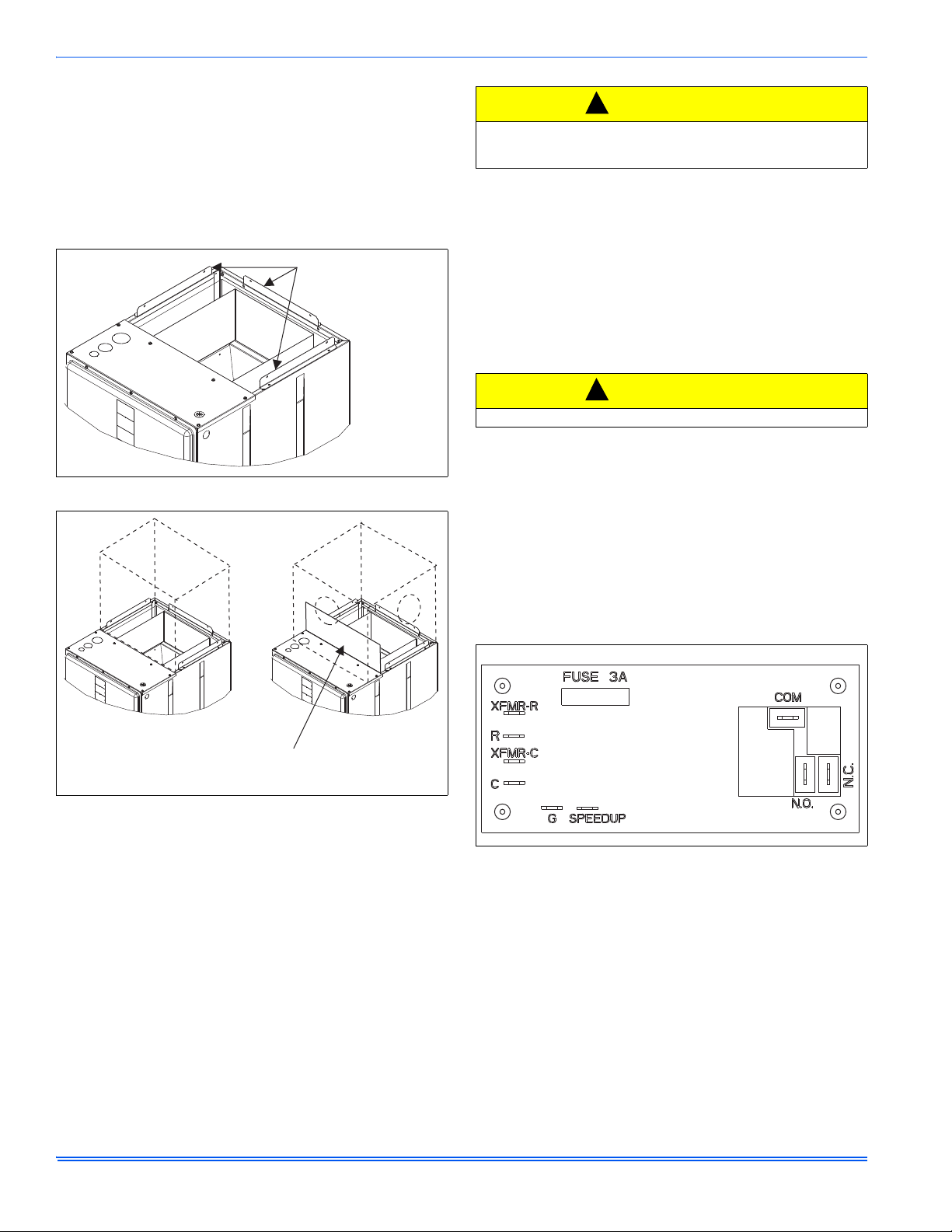
SECTION VIII: BLOWER SPEED
CONNECTIONS
Adjust blower motor speed to provide airflow within the minimum and
maximum limits approved for indoor coil, electric heat and outdoor unit.
Speed tap adjustments are made at the motor terminal block. Airflow
data is shown in Table 10.
Connect motor wires to motor speed tap receptacle for speed desired.
See unit wiring label for motor wiring details.
Blower Speed Connections
FIGURE 11: Blower Speed Connections
SECTION IX: UNIT DATA
TABLE 2:
Models MP08B MP12B MP14D MP16C MP20D
Blower - Diameter x Width
Motor
Voltage
Full Load Amps @230V
Filter
Shipping / Operating Weight (lbs.)
1. Field supplied.
TABLE 3:
1. FLA = Full Load Amps
2. MOP = Maximum Overcurrent Protection device; must be HACR type service disconnect or time delay fuse. Refer to the latest edition of the National Electric Code or in Canada
8 Johnson Controls Unitary Products
Physical and Electrical Data - Cooling Only
10 x 8 10 x 8 10 x 10 10 x 10 10 x 10
HP
Nominal RPM
1/4 HP 1/2 HP 1/2 HP 1/2 HP 1 HP
850 1085 1085 1040 1007
208/230 208/230 208/230 208/230 208/230
1.4 2.6 2.8 2.9 4.1
Type DISPOSABLE OR PERMANENT
Size
1
Bottom Rack Kit
Permanent Type Kit
16 x 20 x 1 16 x 20 x 1 22 x 20 x 1 20 x 20 x 1 22 x 20 x 1
1BR01117 1BR01117 1BR01124 1BR01121 1BR01124
1PF0601 1PF0601 1PF0603 1PF0602 1PF0603
52/51 52/51 75/74 68/67 75/74
Electrical Data - Co oling Only
Models
Motor FLA
1
MP08B 1.4 1.8 15
MP12B 2.6 3.3 15
MP14D 2.8 3.5 15
MP16C 2.9 3.6 15
MP20D 4.1 5.1 15
the Canadian electrical Code and local codes to determine correct wire sizing.
Minimum Circuit Ampacity
MOP
2
Page 9

1190828-UIM-G-0915
TABLE 4:
Electrical Heat: - Minimum Fan Speed
Heater Kit Models
1,2
Nom. kW
@240V
Air Handler Models
MP08B MP12B MP14D MP16C MP20D
6HK(0,1)6500206 2.4kW Low Low Low Low Low
6HK(0,1)6500506 4.8kW Low Low Low Low Low
6HK(0,1)6500806 7.7kW Low Low Low Low Low
6HK(0,1)6501006 9.6kW Low Low Low Low Low
6HK(1,2)6501306 12.5kW Med Low Low Low Low
6HK(1,2)6501506 14.4kW – Med Low Low Low
6HK(1,2)6501806 17.3kW – Med Low Low
6HK(1,2)6502006 19.2kW – Med Med High
1. (0,1) - 0 = no service disconnect OR 1 = with service disconnect.
2. (1,2) - 1 = with service disconnect, no breaker jumper bar OR 2 = with service disconnect & breaker jumper bar.
Low
Low
TABLE 5: KW & MBH Conversions - For Total Power Input Requirement
For a power distribution voltage that is different than the provided nominal voltage, multiply the kW and MBH data from the table by the conversion
factor in the following table.
DISTRIBUTION POWER NOMINAL VOLTAGE CONVERSION FACTOR
208V 240V 0.75
220V 240V 0.84
230V 240V 0.92
TABLE 6:
Electric Heat Performance Data: 208/230-1-60
Heater
Models
1,2
Nominal kW
@240V
Total Heat
3
kW Staging
kW MBH W1 Only W1 + W2
208V 230V 208V 230V 208V 230V 208V 230V
6HK(0,1)6500206 2.4 1.8 2.2 6.2 7.5 1.8 2.2 1.8 2.2
6HK(0,1)6500506 4.8 3.6 4.4 12.3 15 3.6 4.4 3.6 4.4
6HK(0,1)6500806 7.7 5.8 7.1 19.7 24.1 5.8 7.1 5.8 7.1
1PH
6HK(0,1)6501006 9.6 7.2 8.8 24.6 30.1 7.2 8.8 7.2 8.8
6HK(1,2)6501306 12.5 9.4 11.5 32 39.2 3.1 3.8 9.4 11.5
6HK(1,2)6501506 14.4 10.8 13.2 36.9 45.1 3.6 4.4 10.8 13.2
6HK(1,2)6501806 17.3 13 15.9 44.3 54.2 6.5 7.9 13 15.9
6HK(1,2)6502006 19.2 14.4 17.6 49.2 60.2 7.2 8.8 14.4 17.6
1. (0,1) - 0 = no service disconnect OR 1 = with service disconnect.
2. (1,2) - 1 = with service disconnect, no breaker jumper bar OR 2 = with service disconnect & breaker jumper bar.
3. For different power distributions, see conversion table.
Johnson Controls Unitary Products 9
Page 10

1190828-UIM-G-0915
TABLE 7:
Electrical Data For Single Source Power Supply: 208/230-1-60
Air Handler Models
Heater
Models
1,2
Heater
Amps @240V
Field Wiring
Min. Circuit Ampacity
MOP.
3
208V 230V 208V 230V
6HK(0,1)6500206 10 12.4 13.7 15 15
6HK(0,1)6500506 20 23.2 25.7 25 30
MP08B
6HK(0,1)6500806 32 36.4 40.3 40 45
6HK(0,1)6501006 40 44.9 49.6 45 50
6HK(1,2)6501306 52 58.1 64.3 60 70
6HK(0,1)6500206 10 13.8 15.2 15 20
6HK(0,1)6500506 20 24.6 27.2 25 30
6HK(0,1)6500806 32 37.8 41.8 40 45
MP12B
6HK(0,1)6501006 40 46.2 51.1 50 60
6HK(1,2)6501306 52 59.4 65.8 60 70
6HK(1,2)6501506 60 67.8 75.0 70 80
6HK(1,2)6501806 72 81.1 89.7 90 90
6HK(1,2)6502006 80 89.5 98.9 90 100
6HK(0,1)6500206 10 14.0 15.5 15 20
6HK(0,1)6500506 20 24.8 27.4 30 30
6HK(0,1)6500806 32 38.0 42.1 40 45
MP14D
6HK(0,1)6501006 40 46.4 51.3 50 60
6HK(1,2)6501306 52 59.7 66.0 60 70
6HK(1,2)6501506 60 68.1 75.2 70 80
6HK(1,2)6501806 72 81.3 89.9 90 90
6HK(1,2)6502006 80 89.7 99.2 90 100
6HK(0,1)6500206 10 14.1 15.6 15 20
6HK(0,1)6500506 20 24.9 27.5 30 30
6HK(0,1)6500806 32 38.1 42.2 40 45
MP16C
6HK(0,1)6501006 40 46.5 51.5 50 60
6HK(1,2)6501306 52 59.8 66.1 70 70
6HK(1,2)6501506 60 68.2 75.4 70 80
6HK(1,2)6501806 72 81.4 90.0 90 90
6HK(1,2)6502006 80 89.8 99.3 90 100
6HK(0,1)6500206 10 15.5 17.1 20 20
6HK(0,1)6500506 20 26.3 29.0 30 30
6HK(0,1)6500806 32 39.5 43.7 40 45
MP20D
6HK(0,1)6501006 40 47.9 53.0 50 60
6HK(1,2)6501306 52 61.1 67.6 70 70
6HK(1,2)6501506 60 69.5 76.9 70 80
6HK(1,2)6501806 72 82.8 91.5 90 100
6HK(1,2)6502006 80 91.2 100.8 100 110
1. (0,1) - maybe 0 (no service disconnect) or 1 (with service disconnect).
2. (1,2) maybe 1 (with service disconnect, no breaker jumper bar) or 2 (with service disconnect & breaker jumper bar).
3. MOP = Maximum Overcurrent Protection device; must be HACR type circuit breaker or time delay fuse. Refer to the latest edition of the National Electric Code or in
Canada the Canadian electrical Code and local codes to determine correct wire sizing.
10 Johnson Controls Unitary Products
Page 11

1190828-UIM-G-0915
TABLE 8:
Electrical Data For Multi-source Power Supply: 208/230-1-60
Air Handlers
Models
Heater
Models
1, 2
Total Heater
Amps @240V
Min. Circuit Ampacity
MOP
208V 230V 208V 230V
Circuit Circuit
1st
3
2nd
1st
3
2nd
1st
3
2nd
3
1st
3
2nd
MP08B 6HK16501306 52 20.5 37.6 22.5 41.5 25 40 25 45
6HK16501306 52 22 37.6 24 41.5 25 40 25 45
MP12B
6HK16501506 60 24.9 43.3 27.2 47.9 25 45 30 50
6HK16501806 72 42.3 39 46.4 43.1 45 40 50 45
6HK16502006 80 46.6 43.3 51.2 47.9 50 45 60 50
6HK16501306 52 22.3 37.6 24.3 41.5 25 40 25 45
MP14D
6HK16501506 60 25.2 43.3 27.5 47.9 30 45 30 50
6HK16501806 72 29.5 39 46.6 43.1 30 40 50 45
6HK16502006 80 32.4 43.3 51.4 47.9 35 45 60 50
6HK16501306 52 22.4 37.6 24.4 41.5 25 40 25 45
MP16C
6HK16501506 60 25.3 43.3 27.6 47.9 30 45 30 50
6HK16501806 72 42.6 39 46.8 43.1 30 40 50 45
6HK16502006 80 47.0 43.3 51.5 47.9 35 45 60 50
6HK16501306 52 23.9 37.6 25.9 41.5 25 40 30 45
MP20D
6HK16501506 60 26.8 43.3 29.1 47.9 30 45 30 50
6HK16501806 72 44.1 39 48.3 43.1 45 40 50 45
6HK16502006 80 48.5 43.3 53 47.9 50 45 60 50
1. (0,1) - maybe 0 (no service disconnect) or 1 (with service disconnect).
2. (1,2) maybe 1 (with service disconnect, no breaker jumper bar) or 2 (with service disconnect & breaker jumper bar).
3. MOP = Maximum Overcurrent Protection device; must be HACR type circuit breaker or time delay fuse. The 1st Circuit includes the blower motor amps. Refer to the
latest edition of the National Electric Code or in Canada the Canadian electrical Code and local codes to determine correct wire sizing.
Johnson Controls Unitary Products 11
Page 12

1190828-UIM-G-0915
TABLE 9:
Air Flow Data (CFM)
MP Models CM Models
1
Blower
Motor Speed
0.10 0.20 0.30 0.40 0.50 0.60 0.70
External Static Pressure (in. wc.)
208 Volts
High 975 965 953 926 889
CM18B
MP08B
CM24B
Medium 729 719 700 643 614
Low 576 561 501 455 407
High 950 944 927 907 876
Medium 713 703 686 656 591
Low 560 546 511 448 398
High 1459 1410 1342 1275 1200
CM30B
MP12B
CM36B
Medium 1241 1210 1156 1110 1044
Low 992 965 940 911 867
High 1487 1438 1383 1315 1245
Medium 1226 1202 1166 1119 1079
Low 959 950 925 892 866
High 1944 1891 1832 1767 1693
CM30D
Medium 1518 1494 1470 1425 1377
Low 1208 1198 1180 1155 1019
High 1967 1920 1848 1781 1710
MP14D
CM36D
Medium 1520 1508 1486 1446 1398
Low 1207 1202 1176 1156 1028
High 1949 1912 1854 1791 1715
CM42D
Medium 1538 1521 1492 1458 1406
Low 1197 1190 1179 1128 1052
High 1776 1709 1646 1573 1491
CM36C
Medium 1591 1545 1486 1424 1300
Low 1360 1331 1285 1194 1097
High 1746 1687 1616 1536 1386
MP16C
CM42C
Medium 1564 1507 1451 1388 1246
Low 1339 1301 1258 1136 1052
High 1817 1756 1678 1599 1511
CM48C
Medium 1673 1618 1542 1477 1349
Low 1448 1419 1362 1281 1136
High 2035 1994 1922 1858 1781
CM42D
Medium 1849 1819 1771 1694 1650
Low 1679 1654 1624 1578 1526
High 2061 2001 1937 1871 1780
CM48D
MP20D
CM60D
Medium 1867 1835 1786 1727 1653
Low 1678 1657 1615 1572 1518
High 2021 1979 1897 1833 1751
Medium 1852 1811 1758 1697 1639
Low 1646 1630 1596 1555 1491
High 1867 1832 1784 1729 1652
CM64D
Medium 1498 1484 1443 1411 1361
Low 1128 1122 1115 1096 1020
1. Air handler units have been tested to UL 1995 / CSA 22.2 standards up to 0.50" wc. external static pressure.
Dry coil conditions only, tested without filters.
For optimal performance, external static pressures of 0.2" to 0.5" are recommended. Applications above 0.5" are not recommended.
772 724
540 354
289 209
838 742
533 478
294 208
1129 1022
1002 917
822 758
1150 1073
1007 945
818 716
1594 1303
1186 1071
968 830
1623 1532
1203 1101
970 885
1645 1358
1265 1144
998 903
1328 1171
1173 1066
1027 941
1265 1147
1148 998
994 876
1296 1120
1138 915
1001 948
1658 1562
1575 1364
1339 1263
1684 1570
1563 1328
1441 1235
1668 1521
1547 1389
1384 1247
1572 1462
1233 1138
967 893
12 Johnson Controls Unitary Products
Page 13

1190828-UIM-G-0915
TABLE 9:
Air Flow Data (CFM)1 (Continued)
MP Models CM Models
Blower
Motor Speed
External Static Pressure (in. wc.)
0.10 0.20 0.30 0.40 0.50 0.60 0.70
230 Volts
High 1142 1126 1093 1057 1009
CM18B
MP08B
CM24B
Medium 855 840 826 798 756
Low 676 663 638 584 528
High 1105 1088 1060 1030 987
Medium 825 815 802 780 752
Low 655 636 616 569 504
High 1521 1471 1397 1322 1241
CM30B
MP12B
CM36B
Medium 1369 1329 1281 1224 1166
Low 1130 1107 1071 1029 972
High 1557 1507 1440 1363 1289
Medium 1351 1321 1266 1207 1153
Low 1103 1083 1056 1024 976
High 2092 2038 1958 1884 1795
CM30D
Medium 1725 1697 1634 1598 1534
Low 1374 1366 1339 1316 1250
High 2099 2040 1980 1903 1814
MP14D
CM36D
Medium 1725 1694 1652 1605 1541
Low 1388 1372 1340 1306 1277
High 2083 2033 1960 1894 1820
CM42D
Medium 1690 1662 1623 1587 1534
Low 1399 1393 1370 1338 1269
High 1850 1785 1705 1625 1541
CM36C
Medium 1693 1642 1574 1499 1378
Low 1512 1465 1407 1324 1225
High 1815 1754 1680 1593 1472
MP16C
CM42C
Medium 1670 1613 1554 1473 1311
Low 1488 1445 1376 1259 1181
High 1886 1818 1739 1646 1567
CM48C
Medium 1742 1683 1622 1538 1461
Low 1563 1512 1455 1399 1234
High 2123 2076 2001 1926 1840
CM42D
Medium 1999 1959 1896 1821 1744
Low 1851 1819 1768 1698 1626
High 2178 2107 2034 1953 1878
CM48D
MP20D
CM60D
Medium 2014 1965 1905 1843 1761
Low 1867 1832 1779 1727 1661
High 2132 2052 1993 1899 1813
Medium 1985 1941 1872 1798 1729
Low 1848 1810 1758 1695 1627
High 2069 2011 1929 1848 1755
CM64D
Medium 1962 1902 1832 1758 1675
Low 1833 1787 1734 1667 1581
1. Air handler units have been tested to UL 1995 / CSA 22.2 standards up to 0.50" wc. external static pressure.
Dry coil conditions only, tested without filters.
For optimal performance, external static pressures of 0.2" to 0.5" are recommended. Applications above 0.5" are not recommended.
953 852
696 594
482 404
948 859
678 591
467 345
1161 1057
1092 1015
910 842
1185 1125
1076 1019
928 851
1714 1591
1454 1179
1070 904
1680 1605
1467 1182
1106 1026
1720 1459
1460 1233
1159 1073
1373 1242
1261 1145
1101 1022
1278 1206
1210 1082
1056 979
1348 1163
1237 1121
1086 1019
1744 1439
1651 1347
1544 1269
1775 1604
1660 1351
1544 1280
1733 1594
1648 1507
1548 1355
1651 1402
1558 1335
1382 1269
Johnson Controls Unitary Products 13
Page 14

1190828-UIM-G-0915
Take measurements here if
using a filter rack.
Return air static must be
taken between the filter and
indoor coil.
A0395-001
SECTION X: MAINTENANCE
Filters must be cleaned or replaced when they become dirty. Inspect at
least once per month. The frequency of cleaning depends upon the
hours of operation and the local atmospheric conditions. Clean filters
keep unit efficiency high.
COIL CLEANING
If the coil needs to be cleaned, it should be cleaned with water.
LUBRICATION
The bearings of the blower motor are permanently lubricated.
CONDENSATE DRAINS
During the cooling season check the condensate drain lines to be sure
that condensate is flowing from the primary drain but not from the
secondary drain. If condensate ever flows from the secondary drain the
unit should be promptly shut off and the condensate pan and drains
cleaned to insure a free flowing primary drain.
SECTION XI: AIR SYSTEM ADJUSTMENT
To check the Cubic Feet per Minute (CFM), measure external duct
static using a manometer and static pressure tips. To prepare coil for
static pressure drop measurements run the fan only to assure a dry coil.
NOTICE
Refer to Table 10 for coil Air Flow Data of Cubic Feet Per Minute
(CFM). Run the fan on the highest speed to be used.
Drill 2 holes, one 12” away from the air handler in the supply air duct
and on 12” away from the air handler in the return air duct (before any
elbows in the duct work). Insert the pressure tips, and energize the
blower motor. See Table 10 to determine the air flow, and make the
necessary adjustments to keep the CFM within the airflow limitations of
the coil.
EXTERNAL DUCT STATIC
Measure the supply air static pressure. Record this positive number.
Measure the return air static pressure. Record this negative number.
Treat the negative number as a positive, and add the two number s together to determine the total external system static pressure. If a filter
rack is installed on the return air end of the air handler or indoor coil section, make sure to measure the return air duct static between the filter
and the indoor coil.
FIGURE 12: Duct Static Measurements
14 Johnson Controls Unitary Products
Page 15

SECTION XII: WIRING DIAGRAM
BLOWER
MOTOR
RC
XFORMER
BLK
RED/WHT
RED/
WHT
PRP
PRP
BLU/WHT
BLU/WHT
GRN FAN
BRN
WHT
ORG
RED 24V (HOT)
BLU 24V (COM)
ELECTRIC HEAT
1st STAGE
AUXILIARY HEAT
2nd STAGE
BRN
GRN
PRP
BLK
H M L
EQUIPMENT
GROUND
BLK
RED/WHT
{
208-240 VAC 60HZ
1 PHASE SUPPLY
24V
240V
COM
208V
XFORMER
BLOWER
MOTOR
N.O.
N.C.
COM
BLOWER
CONTROL
RELAY
RED
GRN
BLU
WHT
BRN
BLOWER CONTRL COIL
USE COPPER CONDUCTORS ONLY.
IF ALUMINUM CONDUCTORS ARE PRESENT,
ALL APPLICABLE LOCAL AND NATIONAL
CODES MUST BE FOLLOWED.
SEE INSTALLATION INSTRUCTIONS FOR PROPER
LOW VOLTAGE FIELD WIRING CONNECTIONS.
LEGEND
LS - LIMIT SWITCH
SEQ - SEQUENCER
HE - HEATING ELEMENT
FL - FUSIBLE LINK
H - SEQUENCER HEATER
RC - RUN CAPACITOR
RLY - RELAY
H
H
H
H
H
H
5134584-UWD-A-0615
10 KW AND BELOW
RC
13 KW AND ABOVE
XFMR-C
XFMR-R
C
R
G
SPEEDUP
N.O.
N.C.
COM
BLOWER
TIME
DELAY
24V
240V
COM
208V
1
2
3
4
5
6
1
2
3
4
5
6
BLOWER
MOTOR
RC
PRP
BRN
GRN
BLK
H M L
PRP
BLOWER
MOTOR
RC
ALTERNATE
CONNECTION
AP60
RFCX60
MP20
ALT
CONN
L2
L1
L2
L1
HE1
HE2
LS
LS
HE3
LS
H
H
FL
FL
FL
3
1
5
4
SEQ2
SEQ1
RED/WHT
EQUIPMENT
GROUND
YEL
BRN
YEL
BLK
RED
BRN
WHT
BLU
PRP
BLU
RED
BLU
BLU
HE4
LS
FL
H
H
3
1
5
4
BLU
BLK
BLU
L2
L1
RED/WHT
EQUIPMENT
GROUND
YEL
BLK
WHT
BLU
PRP
YEL
BLU
HE1
LS
FL
WHEN INSTALLING HEATER KIT, BE SURE THE BLOWER SPEED IS
SET TO THE SPEED SPECIFIED FOR THE AIR HANDLER/HEATER KIT
COMBINATION ON THIS UNIT'S INSTALLATION INSTRUCTIONS.
HEATER KITS:
6HK*6500206
6HK*6500506
HEATER KITS:
6HK*6501806
6HK*6502006
1
2
3
4
5
6
1
2
3
4
5
6
HEATER KITS:
6HK*6501306
6HK*6501506
L2
L1
L2
L1
HE1
HE2
LS
LS
HE3
LS
FL
FL
FL
SEQ2
SEQ1
RED/WHT
EQUIPMENT
GROUND
BLK
RED
YEL
BLK
RED
BLK
BRN
WHT
BLU
PRP
BLU
YEL
BLU
1
2
3
4
5
6
L2
L1
HE2
LS
FL
RLY 2
RLY 1
RED/WHT
EQUIPMENT
GROUND
YEL
BLK
BLU
YEL
WHT
BLU
PRP
BLU
BLU
HE1
LS
FL
WHT
HEATER KITS:
6HK*6500806
6HK*6501006
1
2
3
4
5
6
RLY
BLU
BLU
BLU
YEL
YEL
RLY
BLU
BLU
BLU
YEL
BLU
YEL
BRN
RLY 2
RLY 1
YEL
BLK
BLK
BLK
RED
RED
BLU
YEL
WHT
BLU
3
1
5
4
H
H
3
1
5
4
H
H
SEQ or RLY
SEQ or RLY
AIR HANDLER - WITH NO HEAT KIT
WIRING DIAGRAM
208-240 VOLT
HE5
LS
FL
HE4
LS
FL
HE3
LS
FL
HE2
LS
FL
HE1
LS
FL
YEL
OD UNIT CONTACTOR
SEQ or RLY
SEQ or RLY
SEQ or RLY
SEQ or RLY
SEQ or RLY
SEQ or RLY
SEQ or RLY
SEQ or RLY
1190828-UIM-G-0915
FIGURE 13: Wiring Diagram - PSC - Single Phase Heat Kits
Johnson Controls Unitary Products 15
Page 16

1190828-UIM-G-0915
A0370-002
W2
X/L
X/L
X/LX/L
FIELD INSTALLED
JUMPER IF SINGLE
STAGE THERMOSTAT
IS USED.
SECTION XIII: TYPICAL THERMOSTAT CONNECTIONS
FIGURE 14: Typical Wiring Diagram - PSC
16 Johnson Controls Unitary Products
Page 17

SECTION XIV: START UP SHEET
Residential Air Handler
with Electric Heat Start-Up Sheet
Proper start-up is critical to customer comfort and equipment longevity
Other Jumpers
(Check all that apply)
Equipment Data
Blower Type
&
Set-Up
A B C D
A
B
C D
Total external static pressure
Supply Return
Condensate drain properly connected per the installation instructions Condensate trap has been primed with water
Duct connections are complete:
Number of filters Filter size
Unit is level
Filters installed
Retrofit
New Construction
Down flow
Up flow Horizontal Left
Horizontal Right
Ground connected
Start-Up TechnicianCompany Name
208 volts AC 230 volt AC
Line Voltage Measured (Volts AC)
Supply static (inches of water column)
Supply air dry bulb temperature
Return air dry bulb temperature
Temperature drop
1 2 3 4 5
Low Medium Low Medium Medium High High
A B C D
Outside air dry bulb temperature
Return air wet bulb temperature
Supply air wet bulb temperature
Return static (inches of water column)
Electrical Connections & Inspection (Complete all that apply)
Continued on next Page
ECM
X-13
PSC
A
B
C D
Low voltage value between "R" and "C" at control board (Volts AC)
Thermostat wiring is complete Thermostat cycle rate or heat anticipator adjusted to Installation Manual specifications
AC
HP
ML
H
NOYES
Equipment Data
Air Flow Setup
COOL
ADJUST
DELAY
HEAT
HUM STAT
AC/HP
CONT FAN
Name Address
City State or Province Zip or Postal Code
Daytime Phone
Unit Model # Unit Serial #
Transformer wired properly for primary supply voltageInspect wires and electrical connections
Unit Location and Connections (Check all that apply)
General Information (Check all that apply)
Start-Up Date
Filters
Owner Information
Print Form Reset Form
1190828-UIM-G-0915
Johnson Controls Unitary Products 17
Page 18

Explain operation of system to equipment owner
Explain the importance of regular filter replacement and equipment maintenance
Clean Up Job Site
Owner Education
Comments and Additional Job Details
Provide owner with the owner's manual
Explain thermostat use and programming (if applicable) to owner
Unit Operation and Cycle Test
(Complete all that apply)
Operate the unit through continuous fan cycles from the thermostat, noting and correcting any problems
Operate the unit through cooling cycles from the thermostat, noting and correcting any problems
Operate the unit through mechanical heating cycles from the thermostat, noting and correcting any problems
Operate the unit through emergency heating cycles from the thermostat, noting and correcting any problems
Job site has been cleaned, indoor and outdoor debris removed from job site
Tools have been removed from unit
All panels have been installed
Heating return air
dry bulb temperature
Number
of elements
Heating supply air
dry bulb temperature
Air temperature rise
Electric heat kit - Model number Serial number Rated KW
Heater 1
Heater 6
Heater 3
Heater 5
Heater 2
Heater 4
Heater 1
Heater 4
Heater 2
Heater 5
Heater 3
Heater 6
Electric Heat
(Complete all that apply)
Measured Voltage
Measured Amperage
Subject to change without notice. Published in U.S.A 1190828-UIM-G-0915
Copyright © 2015 by Johnson Controls, Inc. All rights reserved. Supersedes: 1190828-UIM-F-0915
York International Corp.
5005 York Drive
Norman, OK 73069
 Loading...