

Page 1
MICROPROCESSOR BASED TURBINE FLOW METER
Installation and Operation Guide
2013-3
11451 Belcher Road South, Largo FL 33773 • USA • Tel +1 (727) 447-6140 • Fax +1 (727) 442-5699
www.onicon.com • sales@onicon.com
04-18
Page 2

SAFETY INFORMATION
i
!
!
This meter was calibrated at the factory before shipment. To ensure correct use of the meter, please read
this manual thoroughly.
Regarding this manual:
• This manual should be passed on to the end user.
• Before use, read this manual thoroughly to comprehend its contents.
• The contents of this manual may be changed without prior notice.
• All rights reserved. No part of this manual may be reproduced in any form without ONICON’s
written permission.
• ONICON makes no warranty of any kind with regard to this material, including, but not limited
to, implied warranties of merchantability and suitability for a particular purpose.
• All reasonable effort has been made to ensure the accuracy of the contents of this manual.
However, if any errors are found, please inform ONICON.
• ONICON assumes no responsibilities for this product except as stated in the warranty.
• If the customer or any third party is harmed by the use of this product, ONICON assumes
no responsibility for any such harm owing to any defects in the product which were not
predictable, or for any indirect damages.
Safety Precautions:
The following general safety precautions must be observed during all phases of installation,
operation, service, and repair of this product. Failure to comply with these precautions or
with specic WARNINGS given elsewhere in this manual violates safety standards of design,
manufacture, and intended use of the product. ONICON Incorporated assumes no liability for
the customer’s failure to comply with these requirements. If this product is used in a manner not
specied in this manual, the protection provided by this product may be impaired.
The following symbols are used in this manual:
Messages identied as “WARNING” contain information regarding the personal safety of
individuals involved in the installation, operation or service of this product.
Messages identied as “CAUTION” contain information regarding potential damage to the
product or other ancillary products.
WARNING
CAUTION
IMPORTANT NOTE
Messages identied as “IMPORTANT NOTE” contain information critical to the proper
operation of the product.
11451 Belcher Road South, Largo FL 33773 • USA • Tel +1 (727) 447-6140 • Fax +1 (727) 442-5699 • sales@onicon.com
Microprocessor Turbine Flow Meter Manual 04/18 - 2013-3 Page 2
Page 3

TABLE OF CONTENTS
1.0 INTRODUCTION .............................................................................................................4
1.1 Purpose of This Guide ..........................................................................................4
1.2 Typical Turbine Flow Meters ...............................................................................4
1.3 Standard Features and Specications ..................................................................5
1.4 Model Numbering System ....................................................................................6
1.5 Additional Required Hardware ............................................................................6
1.6 Serial Number .......................................................................................................6
2.0 UNPACKING ................................................................................................................7
2.1 Checking That You Have Received Everything ...................................................7
3.0 INSTALLATION, REMOVAL & ADJUSTMENT .............................................................8
3.1 Installation Site Selection ....................................................................................8
3.2 Insertion Meter Straight Run Requirements ......................................................10
3.3 Insertion Meter Mechanical Installation ............................................................11
3.3.1 Insertion Meter Installation Kits ...............................................................12
3.3.2 ONICON Dry Tap Installation Hardware Kits ...........................................12
3.3.3 ONICON Hot Tap Installation Hardware Kits ...........................................12
3.3.4 Customer Supplied Installation Hardware ...............................................13
3.3.5 Conrming the Stack Height .....................................................................14
3.4 Installing the Insertion Meter .............................................................................15
3.4.1 Installing the Meter With a Factory Supplied Depth Gage ......................16
3.4.2 Calculating Insertion Depth Using Conguration Utility ........................16
3.5 Removal of the Insertion Meter ..........................................................................17
3.6 Inline Flow Meter Straight Run Requirements and Mechanical Installation...19
3.7 Wiring Connections ............................................................................................20
4.0 START-UP & COMMISSIONING ...................................................................................21
4.1 Helpful Hints for Start-up and Commissioning ................................................21
4.2 Insertion Meter Start-up and Commissioning ...................................................22
4.3 Insertion Meter Start-up and Commissioning Worksheet .................................23
4.4 Inline Meter Start-up and Commissioning ........................................................24
4.5 Inline Meter Start-up and Commissioning Worksheet ......................................25
4.6 Troubleshooting Guide .......................................................................................26
5.0 ANALOG ADJUSTMENT PROCEDURE .......................................................................27
5.1 Diagnostic LEDs ..................................................................................................28
APPENDIX
A User Connections and Internal Wiring Diagrams
B Installation Hardware Instructions
C Insertion Turbine Assembly Detail Drawings
11451 Belcher Road South, Largo FL 33773 • USA • Tel +1 (727) 447-6140 • Fax +1 (727) 442-5699 • sales@onicon.com
Microprocessor Turbine Flow Meter Manual 04/18 - 2013-3 Page 3
Page 4
SECTION 1.0: INTRODUCTION
!
We, at ONICON Incorporated, would like to thank you for purchasing our quality, U.S. made, turbine
ow meter. As our valued customer, our commitment to you is to provide fast reliable service and
assistance, while continuing to offer you new products to meet your growing ow measurement needs.
1.1 PURPOSE OF THIS GUIDE
We have written this guide to provide the persons responsible for the installation, operation and
maintenance of your turbine ow meter with the most specic equipment information they will
need. This is NOT an electrical or plumbing trade manual.
WARNING
Please do not permit any persons to install, operate or maintain this equipment unless they have a
complete knowledge of their trade skills and are competent to work on high pressure hot and cold
water systems, according to their individual trades. Death or permanent injury may result from
accidents with these systems.
This guide is the basic reference tool for all ONICON Turbine Flow Meters. If you have not
purchased all of the options, there will be references in this manual which are not applicable to
your meter(s).
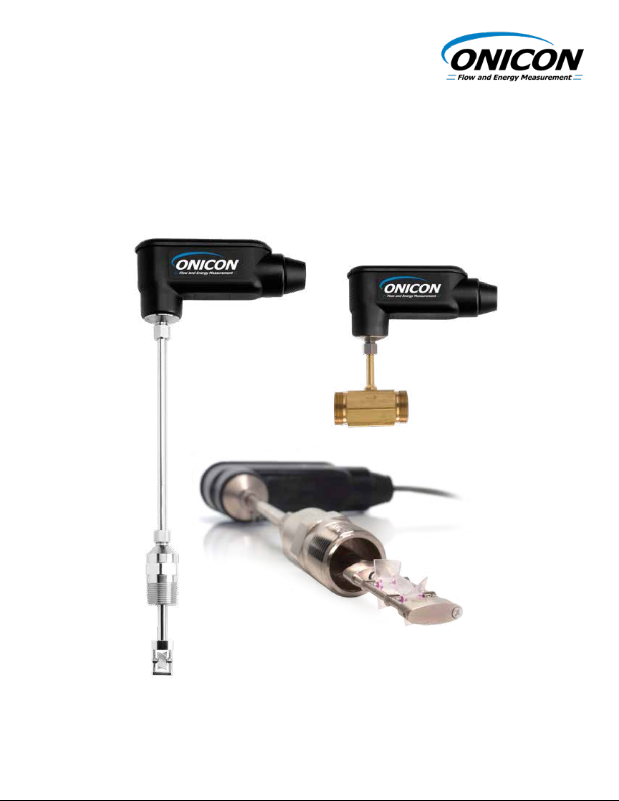
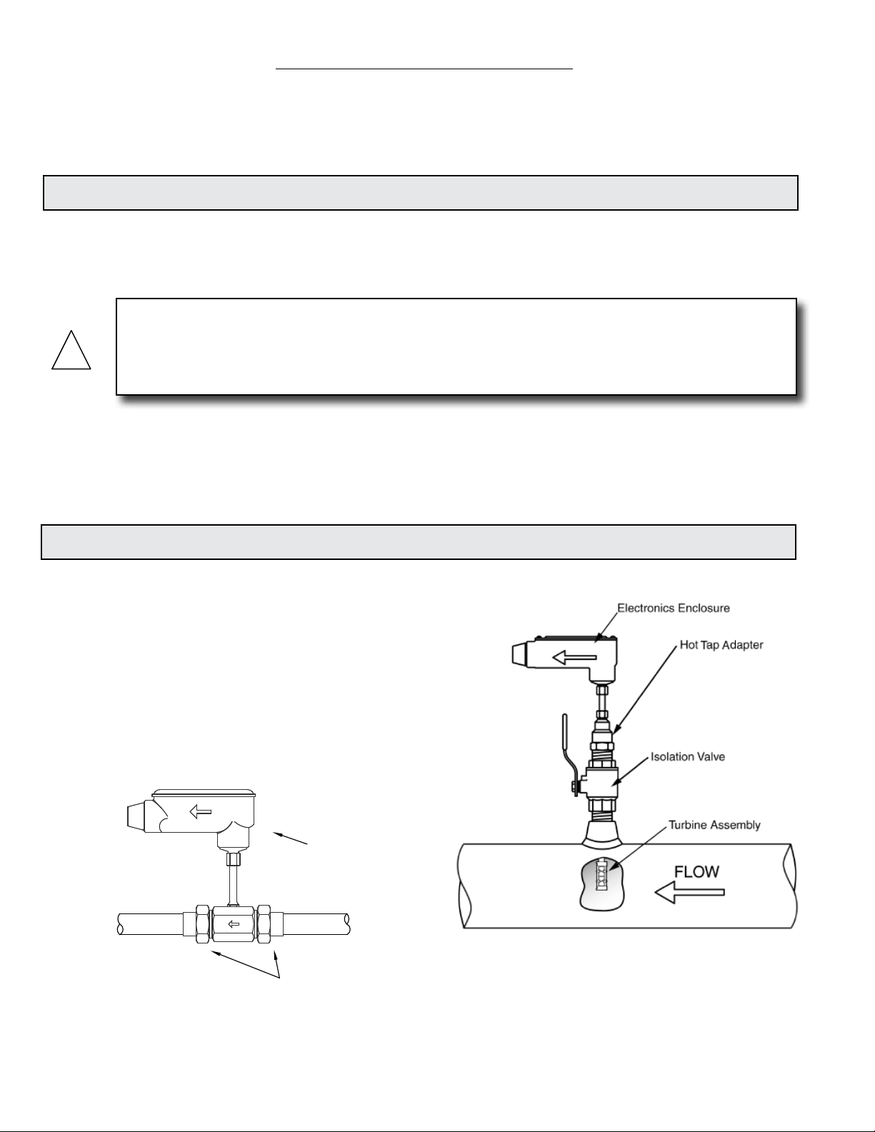
1.2 TYPICAL TURBINE FLOW METERS
ONICON’s Turbine Flow Meters measure the velocity
of owing liquids by counting the frequency at
which the blades of a rotating turbine pass a xed
electrode. Circuitry within the ow meter electronics
enclosure then converts the rotational rate to digital
and/or analog signals which are transmitted via
a connecting cable to any of ONICON’s display
devices, Btu meters and/or a data acquisition system.
Electronics Enclosure
Sweat or NPT
Process Connections
Insertion Meter
Inline Meter
11451 Belcher Road South, Largo FL 33773 • USA • Tel +1 (727) 447-6140 • Fax +1 (727) 442-5699 • sales@onicon.com
Microprocessor Turbine Flow Meter Manual 04/18 - 2013-3 Page 4
Page 5
1.3 STANDARD FEATURES AND SPECIFICATIONS
(Refer to specication sheet for particular model to obtain additional details)
ACCURACY
Insertion Meters
± 0.5% of reading at calibrated velocity
± 1% of reading from 3 to 30 ft/s (10:1 range)
± 2% of reading from 0.4 to 20 ft/s (50:1 range)
Inline Meters
± 0.5% of reading at calibrated velocity
± 2% of reading from 0.8 to 38 GPM (50:1 range)
SENSING METHOD
Single- Turbine Meters
Single turbine electronic impedance sensing
(non-magnetic and non-photoelectric)
Dual-Turbine Meters
Dual turbine electronic impedance sensing
(non-magnetic and non-photoelectric) and
frequency averaging circuitry.
PIPE SIZE RANGE
Single-Turbine Insertion Meters
1¼” through 72” nominal
Dual-Turbine Insertion Meters
2½” through 72” nominal
Inline Meters
¾” or 1” NPT threaded or copper sweat process
connections
SUPPLY VOLTAGE
24±4 V AC/DC at 80 mA
LIQUID TEMPERATURE RANGE
Standard: 180° F continuous, 200° F peak
High Temp: 280° F continuous, 300° F peak
Insertion meters operating above 250° F require 316
stainless steel construction option
AMBIENT TEMPERATURE RANGE
-5° to 160° F (-20° to 70° C)
OPERATING PRESSURE
400 PSI maximum
PRESSURE DROP
Insertion Meters
Less than 1 PSI at 20 ft/s, decreasing
in larger pipes and lower velocities
Inline Meters
3 PSI at maximum ow rate
MATERIAL
Insertion Meters
Wetted metal components
Standard: Electroless nickel plated brass
Optional: 316 stainless steel
Inline Meters
Brass sensor body
ELECTRONICS ENCLOSURE
Standard: Weather-tight aluminum enclosure
(NEMA4)
Optional: Submersible enclosure (NEMA6)
ELECTRICAL CONNECTIONS
Standard: 10’ of PVC jacketed cable with ½”
NPT conduit connection
Optional: Indoor DIN connector with 10’ of
plenum rated cable
OUTPUT SIGNAL(S)
Standard: Calibrated frequency output
0-15 V pulse, Maximum Hz, Scaled Pulse/
Alarm Output (Field Congurable)
Optional: Analog and Iso Analog outputs also
available, based on model
APPROVALS
Optional
TURBINE INSERTION FLOW METER
NSF/ANSI 61 <MH60590>
ALSO CLASSIFIED
IN ACCORDANCE WITH
NSF/ANSI 372
For F-1100 / F-1200 Series Only,
maximum temperature 180° F (82° C)
11451 Belcher Road South, Largo FL 33773 • USA • Tel +1 (727) 447-6140 • Fax +1 (727) 442-5699 • sales@onicon.com
Microprocessor Turbine Flow Meter Manual 04/18 - 2013-3 Page 5
Page 6
1.4 MODEL NUMBERING SYSTEM
METER ORDERING INFORMATION
Meter Model Number Coding = F-1ABB-CC-DD-EFGH
A = Number of Turbines E= Wetted Materials
1 = Single Turbine 1 = Electroless Ni Plated Brass
2 = Dual Turbine 2 = 316 SS
BB = Meter Type 3 = Bronze Body, Inline
00 = Insertion F= Electronics Enclosure
34 = ¾" Inline 2 = NEMA 4 Weathertight Enclosure
01 = 1" Inline 3 = NEMA 6 Submersible Enclosure
CC = Outputs G= Wiring Connection
00 = Freq. and Scaled Pulse 2 = 10’ PVC Jacketed Cable, Pig Tail with ½” Conduit Adapter
10 = Freq., analog and Scaled Pulse 5 = 10' Plenum Rated Cable, DIN Connector
11 = Freq., Iso. Analog, and Scaled Pulse 6 = 25' PVC Jacketed Cable, Pig Tail with ½" Conduit Adapter
DD = Meter Type and Pipe Size Range 7 = 10' Submersible Cable with Connector
A1 = 1.25 - 2.5” (F-1100 Only) H = Process Adapter
B2 = 2.5 – 4.0” (F-1100 Only) 1 = 1" NPT Adapter, Medium Temperature (Temp. </= 150° F)
C3 = 2.5 - 10” 2 = 1" NPT Adapter, High Temperature (Temp. </= 280° F)
D4 = 2.5 - 16” 3 = 1" NPT Adapter, NSF Rated for Domestic Water
E5 = 2.5 - 22” 9 = Inline, coupling adapters based on pipe material
F6 = 2.5 - 72”
00 = Inline
1.5 ADDITIONAL REQUIRED HARDWARE
All ONICON insertion type meters can be installed and removed via a 1” or
larger full port ball valve without stopping ow. The terms “Dry Tap” and
“Hot Tap” refer to the installation method of the isolation valve kit only.
Dry Tap Installation Hardware: For new construction or scheduled
shutdown; once kit is installed, the ow meter can be installed or removed
without system shutdown.
Hot Tap Installation Hardware: For applications which require the access
hole in the pipe to be drilled through the valve using a wet tap drilling
machine while the hydronic system is pressurized and operating.
NOTE: Installation hardware materials vary greatly based on pipe
material, pipe size and dry tap vs. hot tap versions.
1.6 SERIAL NUMBER
Serial Number
The serial number of your ow meter is located on a label on the side of the electronics enclosure.
The model number is also listed on this label. The serial number is a unique identier that you
should refer to, along with the model number, whenever you contact ONICON for assistance
regarding your meter.
11451 Belcher Road South, Largo FL 33773 • USA • Tel +1 (727) 447-6140 • Fax +1 (727) 442-5699 • sales@onicon.com
Microprocessor Turbine Flow Meter Manual 04/18 - 2013-3 Page 6
Page 7

SECTION 2.0: UNPACKING
Turbine ow meters are generally shipped in one package unless optional hardware or equipment is
ordered. This package may contain up to two complete meters along with the optional installation kits.
Any display equipment ordered with the meters, will be packed separately. Please open all packages
with caution to avoid damaging to their contents. In the event that anything is damaged when you
receive it, notify the shipping company immediately and the ONICON customer service department.
Most products are shipped insured unless the customer specically requests otherwise.
2.1 CHECKING THAT YOU HAVE RECEIVED EVERYTHING
The Documentation
Enclosed with each ow meter is a comprehensive documentation package which includes the
following items:
• Installation and Operation Guide
• Flow Meter Calibration Certicate
Please notify the ONICON customer service department if any documents are missing.
The Flow Meter
The ow meter was carefully packed prior to shipment and should arrive without any damage.
Prior to installation, inspect for physical damage such as broken turbine blades or a damaged
stem.
• Test the turbine(s) to see that they rotate freely when you gently blow on them parallel to
their shafts.
• Make sure that the threads on the insertion meter hot tap adapter have not been
damaged.
• Inspect the insertion meter stem for bends or other damage. The stem forms the seal
against liquid leakage as it slides through an ‘O’ ring inside the hot tap adapter. Deep
scratches may cause leakage.
• The serial and model numbers on the laminated wiring connection/calibration data tag
attached to the meter should match the numbers on the tag mounted directly on the ow
meter. Be sure that the unit was calibrated to the correct pipe size and ow range.
11451 Belcher Road South, Largo FL 33773 • USA • Tel +1 (727) 447-6140 • Fax +1 (727) 442-5699 • sales@onicon.com
Microprocessor Turbine Flow Meter Manual 04/18 - 2013-3 Page 7
Page 8
SECTION 3.0: INSTALLATION, REMOVAL & ADJUSTMENT
!
! i !
WARNING
Insertion ow meters may often be installed in pipes which are under high pressure. Accidents
with these systems can cause serious injury or death. Only persons experienced with high pressure
systems and related knowledge in the heating, cooling and uid metering elds should attempt to
install adjust or remove the ow meter. Carefully read the installation and removal instructions in
this manual before performing any work on these meters.
ONICON will be happy to assist with technical recommendations and to provide guidance
by telephone or e-mail. On-site eld engineering, installation and service is also available at
additional cost.
3.1 INSTALLATION SITE SELECTION
Install the ow meter where it will be accessible for personnel to perform necessary periodic
maintenance. The clearance required for insertion meter installations is typically 23”-36” from
the pipe wall to the nearest obstruction above the valve assembly. This clearance dimension will
increase with large diameter pipes. Allow at least 6” of clearance for inline meter installations.
The environment should be free of corrosive liquids/fumes, temperature extremes and heavy
vibration. The following information should be used as a guide to the proper location for
installing the meter.
GENERAL PRACTICES:
1. For best results, install the ow meter in a straight run of pipe, free of bends, tees, valves,
transitions, and obstructions.
2. Straight run requirements vary based on the nature of the upstream obstruction. Review
the following pages for guidelines in determining minimum upstream straight run
requirements based on the nature of the obstruction.
Note: Depending upon specic location details, more or less straight run may be
required to produce a satisfactory ow prole.
3. If there is insufcient straight run, allow 80% of the run upstream and 20% of the run
downstream.
IMPORTANT NOTE
Always use the maximum available straight run. When more than the minimum required
straight run is available, place the meter such that the excess straight run is upstream of the
meter location.
11451 Belcher Road South, Largo FL 33773 • USA • Tel +1 (727) 447-6140 • Fax +1 (727) 442-5699 • sales@onicon.com
Microprocessor Turbine Flow Meter Manual 04/18 - 2013-3 Page 8
Page 9
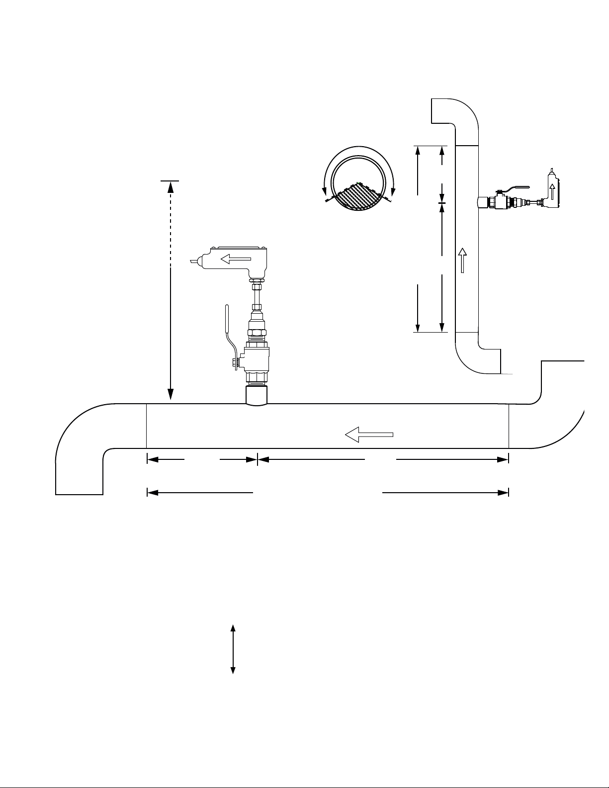
INSERTION AND INLINE FLOW METER SITE SELECTION
GENERAL GUIDELINES
(Shown with Insertion Meter)
• Install in vertical or horizontal pipe.
• For horizontal pipe position meter
anywhere in upper 240°
CLEARANCE
CLEARANCE
REQUIRED
REQUIRED
FOR INSTALLATION
FOR INSTALLATION
23” - 36”
Depending on
23" - 36"
pipe size
Depending on
Allow at least
pipe size
6” for inline meters
FLOW
Downstream
20%
Available Straight Run*
Upstream
80%
Vertical Pipe
FLOW
Position
(Downward ow
is also allowed)
20%
Downstream
80%
Upstream
Available Straight Run*
*See following pages for model specic straight run requirements.
EVALUATING UPSTREAM PIPING CONDITIONS
Straight Pipe
Single Bend
Pipe Reduction or Enlargement
Outowing Tees
Multiple Bends in Same Plane
Multiple Bends Out of Plane
Inowing Tees
Control Valves
Worse Better
11451 Belcher Road South, Largo FL 33773 • USA • Tel +1 (727) 447-6140 • Fax +1 (727) 442-5699 • sales@onicon.com
Microprocessor Turbine Flow Meter Manual 04/18 - 2013-3 Page 9
Page 10
FLOW DIRECTION
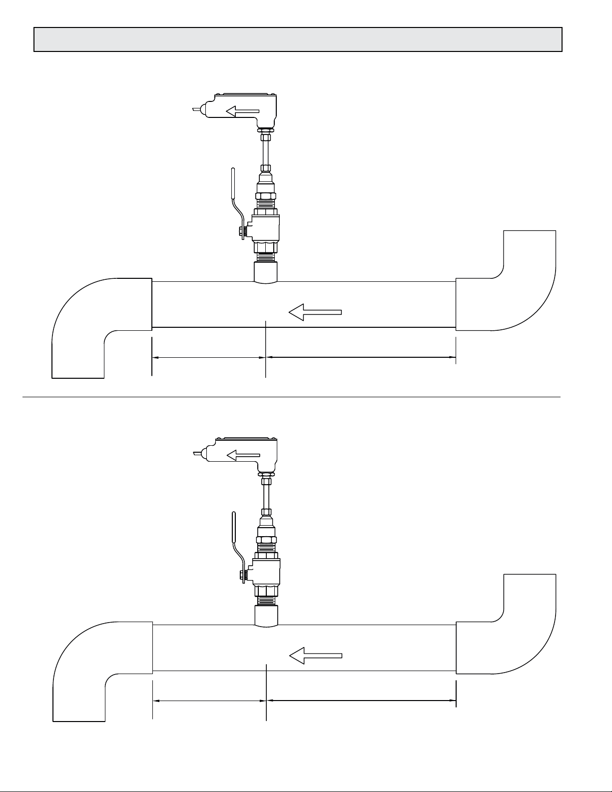
3.2 INSERTION METER STRAIGHT RUN REQUIREMENTS
Series F-1100 Single Turbine Flow Meters
FLOW DIRECTION
Minimum downstream
straight run distance
5 pipe diameters to any
valve, elbow, tting, etc.
GENERAL PRACTICES
1. For best results, install the ow meter in a straight run of pipe,
free of bends, tees, valves, transitions, and obstructions for a
distance of at least 20 pipe diameters upstream and 5 diameters
downstream.
2. Longer straight runs may be required in applications where the
meter is placed downstream from devices which cause unusual
ow prole disruption or swirl, for example, modulating valves or
two elbows in close proximity and out of plane, etc.
3. If there is not sucient straight run, allow 80% of the run upstream and
20% of the run downstream. If the total length of straight run is less
than 20 diameters, performance may seriously
degrade, and consideration should be given to
changing to the series F-1200 Dual Turbine
Flow Meter.
FLOW DIRECTION
Minimum upstream
straight run distance
20 pipe diameters from any
valve, elbow, tting, etc.
Series F-1200 Dual Turbine Flow Meters
GENERAL PRACTICES
1. For best results, install the ow meter in a straight run of pipe,
free of bends, tees, valves, transitions, and obstructions for a
distance of 10 pipe diameters upstream and 5 diameters
downstream.
Minimum downstream
straight run distance
5 pipe diameters to any
valve, elbow, tting, etc.
2. Longer straight runs may be required in applications where the
meter is placed downstream from devices which cause unusual
ow prole disruption or swirl, for example, modulating valves or
two elbows in close proximity and out of plane, etc.
3. If there is not sucient straight run, allow 80% of the run
upstream and 20% of the run downstream.
FLOW DIRECTION
Minimum upstream
straight run distance
10 pipe diameters from any
valve, elbow, tting, etc.
11451 Belcher Road South, Largo FL 33773 • USA • Tel +1 (727) 447-6140 • Fax +1 (727) 442-5699 • sales@onicon.com
Microprocessor Turbine Flow Meter Manual 04/18 - 2013-3 Page 10
Page 11
3.3 INSERTION METER MECHANICAL INSTALLATION
!
! i !
ONICON Insertion Turbine Flow Meters employ a hot tap adapter design that allows for insertion
and removal, when necessary, without interrupting ow and draining the pipe. To take advantage
of this feature, the ow meter must be installed through an isolation valve. The installation must
also allow for sufcient overhead clearance to fully extract the meter, and a full 1” opening in the
pipe wall is required to clear the sensor head and allow for insertion. Make sure that your valves
and ttings are full port and at least 1” in actual internal diameter.
CLEARANCE
REQUIRED
FOR INSTALLATION
Typically
30 - 40"
23”- 36”
depending on
pipe size and
height of valve
assembly.
Dry Tap Installation
Kit for Steel Pipe
Minimum Hole Size = 1"
Must be centered
1" Full port ball valve
1" Close nipple
1" Branch outlet
NOTE: Use stainless steel or brass
close nipple only.
1¼" for
hot tap
CAUTION
ONICON insertion style ow meters must be installed through a valve assembly. Failure to do so
negates the ability to remove the meter without shutting down ow and draining the system. It will
also result in an excessive amount of stem protruding from the pipe. Excessive stem lengths
unnecessarily expose the meter to incidental damage.
IMPORTANT NOTE
11451 Belcher Road South, Largo FL 33773 • USA • Tel +1 (727) 447-6140 • Fax +1 (727) 442-5699 • sales@onicon.com
Microprocessor Turbine Flow Meter Manual 04/18 - 2013-3 Page 11
Flow meters installed through oversized access holes will be subjected to undesirable turbulence
that may affect the accuracy of the meter.
Page 12
3.3.1 Insertion Meter Installation Kits
ONICON offers a wide range of installation hardware kits for commonly used pipe
materials. The kits are specically designed for ONICON insertion ow meters, and their
use is recommended. Refer to Appendix B of detailed information regarding ONICON
installation hardware kits.
The use of ONICON installation hardware kits accomplishes two important objectives.
First, it ensures that the proper hardware is used. Second, it simplies order processing
by standardizing the dimensions of the installation hardware.
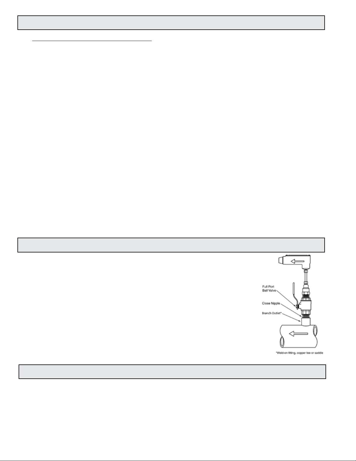
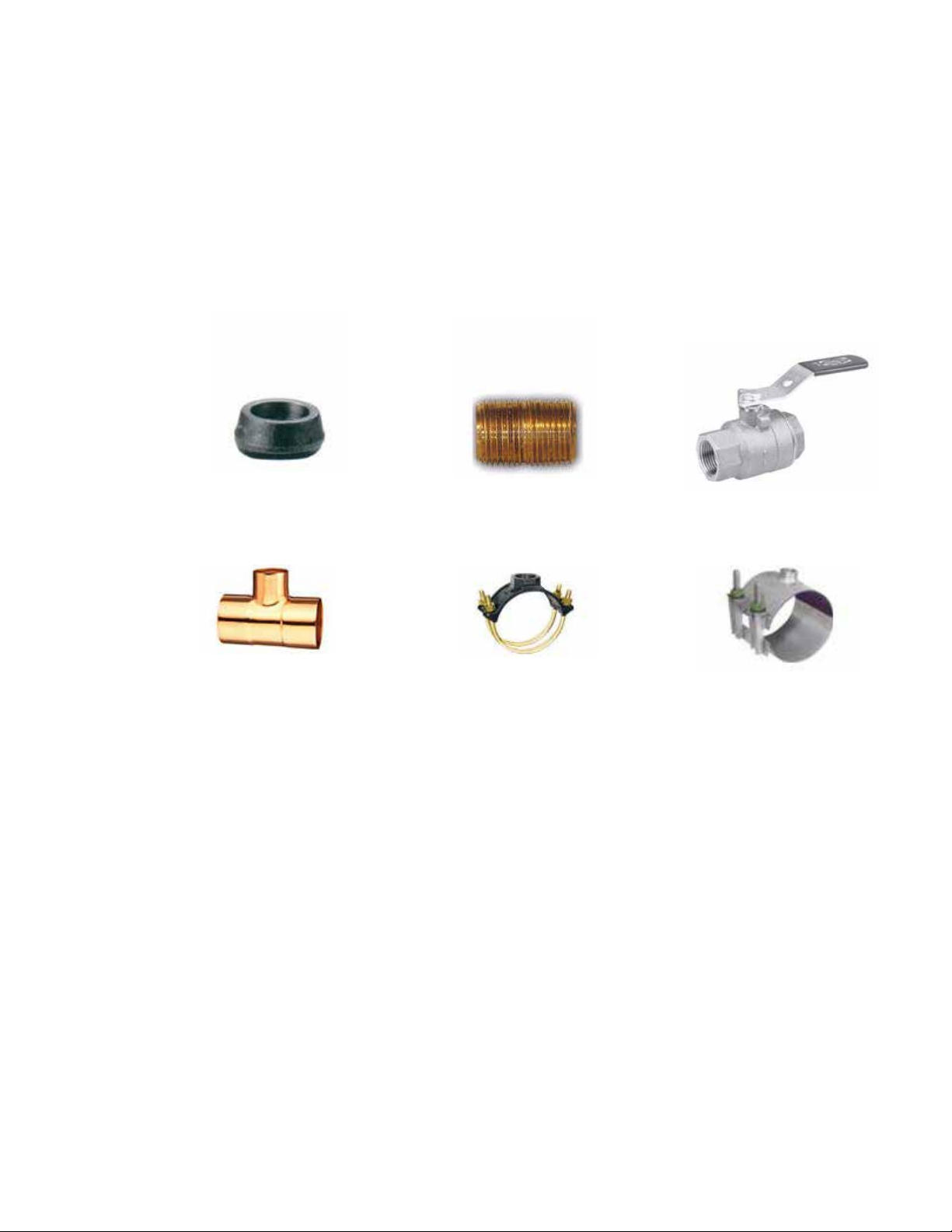
ONICON installation hardware kits consist of three separate component parts:
Some type of threaded
branch outlet,
An interconnecting
close nipple,
And a full port
isolation valve.
Different pipe materials require different branch outlets and may include additional
bushings to properly size the opening.
3.3.2 ONICON Dry Tap Installation Hardware Kits
Dry Tap installation hardware kits are designed to be installed on piping systems that are
drained and at atmospheric pressure. The access hole is drilled (1” minimum) prior to
installation of the branch outlet with 1” NPT threads, the close nipple and full port ball
valve. Once the isolation valve is installed, the piping system can be ushed, lled and
pressurized. The ow meter may now be inserted or removed by hand without having to
stop ow or drain the system. Please read all instructions before proceeding with meter
insertion.
3.3.3 ONICON Hot Tap Installation Hardware Kits
ONICON offers an alternative installation hardware kit when it is not practical to relieve
pressure and drain the system. In this case, a 1¼” branch outlet, a close nipple and a 1¼”
full port ball valve are installed rst. Then, a hot tap drilling apparatus is used to drill a 1”
diameter hole through the valve. This eliminates the need to stop ow and drain the pipe.
Please read all instructions before proceeding with meter insertion.
11451 Belcher Road South, Largo FL 33773 • USA • Tel +1 (727) 447-6140 • Fax +1 (727) 442-5699 • sales@onicon.com
Microprocessor Turbine Flow Meter Manual 04/18 - 2013-3 Page 12
Page 13
!
3.3.4 Customer Supplied Installation Hardware
!
! i !
There are occasions where circumstances require that the customer provide the installation
hardware or that the ow meter be installed through existing hardware. In these cases, it is
important to conrm that the installation hardware is suitable for use with the ow meter
provided by ONICON before it is installed. The installation must allow for sufcient overhead
clearance to fully extract the meter, must not be too tall where the meter cannot reach the
appropriate depth, and a full 1” opening in the pipe wall is required to clear the sensor head
and allow for insertion. Make sure that your valves and ttings are full port and at least 1” in
actual internal diameter.
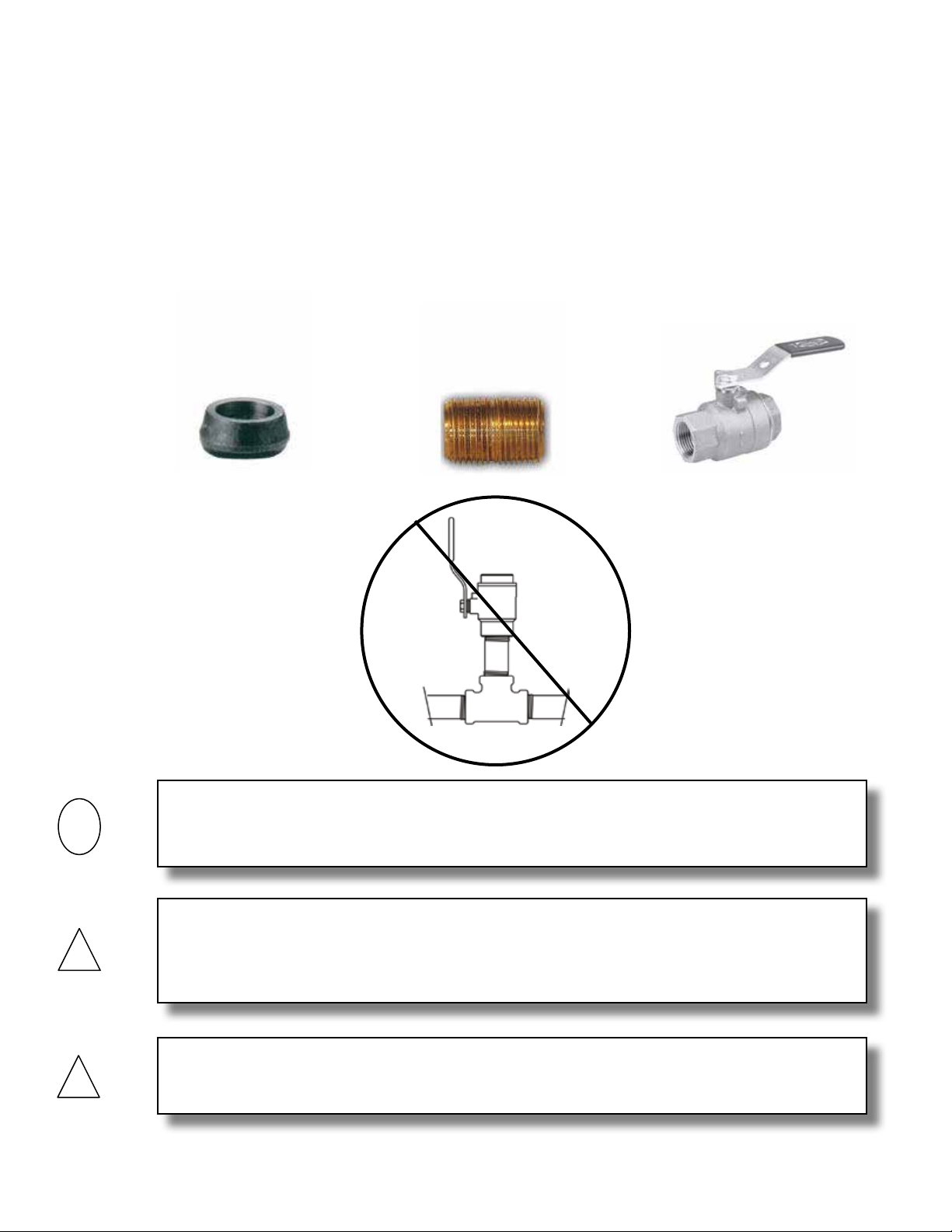
Installation hardware generally consists of three separate component parts:
Some type of threaded
branch outlet,
An interconnecting
close nipple,
And a full port
isolation valve.
IMPORTANT NOTE
Do not use threaded steel or slip PVC tees to provide the 1” opening in the pipe. Tees of this
type will cause signicant errors in the ow measurement.
CAUTION
In order to provide the ow meter with the correct stem length, ONICON must know the
overall height of the installation hardware as measured from the outside wall of the pipe to
the top of the valve where the meter is installed.
CAUTION
Use stainless steel or brass nipple only.
11451 Belcher Road South, Largo FL 33773 • USA • Tel +1 (727) 447-6140 • Fax +1 (727) 442-5699 • sales@onicon.com
Microprocessor Turbine Flow Meter Manual 04/18 - 2013-3 Page 13
Page 14
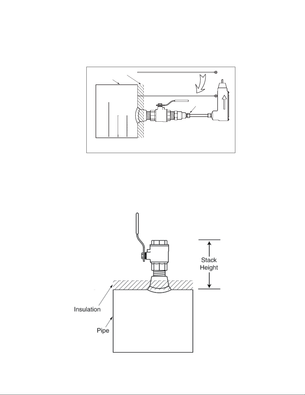
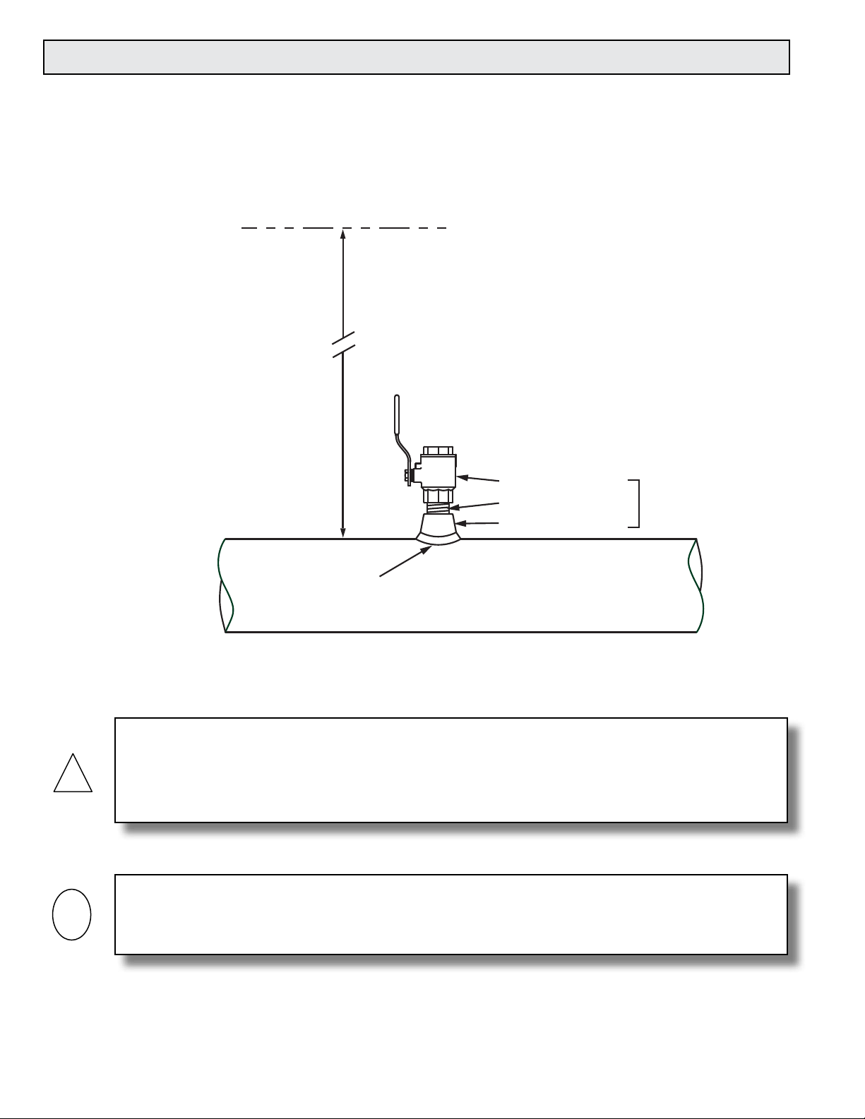
3.3.5 Conrming the Stack Height
STACK HEIGHT 8.5”
ONICON Insertion Turbine Flow Meter stem lengths vary according to the pipe diameter and
the height of the installation hardware stack. ONICON records the stack height dimension
provided by the customer at the time of order entry, and the information is used to size the
stem. This dimension is shown on the laminated insertion depth gage tag attached to the
meter.
Insulation
Pipe
FOR S/N #250791
ANY OTHER METER
DO NOT USE FOR
READ OTHER SIDE OF THIS TAG BEFORE INSTALLING METER
GAGE LENGTH 10.937"
1) Pierce insulation until
gage tip touches pipe.
2) Insert flow meter until
bottom of electronics case
touches eye of depth gage.
Depth Gage
Flow Direction
Lock Nut
3) Confirm arrow is
aligned with flow
and tighten lock nut.
Prior to installing the meter, conrm that the stack height recorded on the tag is close to the
actual stack height. Flow meter stems are intentionally over sized to allow for variations of at
least 2” in the stack height. Contact ONICON prior to installation if there are any questions
regarding stack height or stem length. This will allow ONICON to offer you credit for your
meter if you decide to exchange the meter for one with a different stem length. Returns may
be subject to a restocking fee.
11451 Belcher Road South, Largo FL 33773 • USA • Tel +1 (727) 447-6140 • Fax +1 (727) 442-5699 • sales@onicon.com
Microprocessor Turbine Flow Meter Manual 04/18 - 2013-3 Page 14
Page 15

3.4 INSTALLING THE INSERTION METER
!
!
WARNING
SYSTEM MAY BE UNDER HIGH PRESSURE. When installing the meter, adjusting its position
or removing the meter, be sure to hold the electronics enclosure rmly by hand before SLOWLY
loosening the positioning clamping nut. Failure to do this will allow the pressure to suddenly and
rapidly force the meter from the pipe causing serious injury. The meter could also be damaged or
break apart causing a break in the water seal with the resultant loss of large amounts of water. The
hand effort required to hold the meter will be 0.11 times the pipe pressure.
Begin by calculating the effort that will be required to hold the meter. Establish adequate footing for
this task, taking extra caution when working from a ladder or platform. Use the following formula:
E=0.11xP Where: E = effort in pounds
P = system pressure in pounds per square inch
Example: In a 300 PSI system, 33 pounds of effort is required to insert the meter into the pipe.
WARNING
When you are ready to rell the system, make sure that all lines are lled with water before inserting
the turbine assembly into the stream. If the lines are not lled, air may interrupt the owing stream
and damage the turbine assembly. A greater danger is that if this is a hot water system, some water
may ash into steam and exceed the high temperature limit for the turbine and its mechanical
assembly. This ash over could exceed the pressure ratings of the meter and the assembly could fail
allowing steam and hot water to escape causing serious injury.
1. After tting the necessary plumbing hardware, ush the
entire system so that it is free of ux, solder and slag.
2. Prepare to install the ow meter by loosening the clamping
nut and withdrawing the turbine assembly fully into the
hot tap adapter.
3. Next, thread the adapter on to the ball valve using a paste
type thread sealant. Do not use Teon tape as torn strands
of the tape may wind around the turbine, slowing down or
even stopping the turbine.
4. Check the installation for leaks by slightly opening the
ball valve. An ‘O’ ring in the adapter seals the meter stem
against leakage. If there are any leaks around the clamping
nut or stem, DO NOT ATTEMPT TO STOP THE LEAKAGE
BY OVERTIGHTENING THE CLAMPING NUT. Damage to
this nut or the clamping ring under the nut may prevent
the assembly from properly holding the meter in the pipe.
The clamping nut is not part of the sealing mechanism.
Any leaks in this area indicate that the ‘O’ ring is not
sealing properly and you must contact the factory for
assistance.
Hot Tap
Adapter
Apply Paste
Type Sealant
to Threads
11451 Belcher Road South, Largo FL 33773 • USA • Tel +1 (727) 447-6140 • Fax +1 (727) 442-5699 • sales@onicon.com
Microprocessor Turbine Flow Meter Manual 04/18 - 2013-3 Page 15
Page 16

3.4.1 Installing the Meter with a Factory Supplied Depth Gage:
!
!
! i !
1. Open valve completely, loosen the position
clamping nut, and insert the meter until the
bottom of the electronics case touches the eye
of the depth gage. (Pierce insulation with gage
until the tip touches the pipe.)
2. Position the electronics enclosure parallel to the
pipe in the proper direction relative to the ow.
This will position the turbine with its axis in
line with the ow and in the correct direction.
Insertion Depth
Gage provided
with each meter
Position
Clamping Nut
3. Tighten the position clamping nut. Contact
ONICON for assistance when installing a meter
without a depth gage.
FLOW
CAUTION
Do not release the ow meter until you have tightened the position clamping nut enough to hold the
ow meter in the desired position. This will require less torque than you might think, so be careful
not to overtighten it and risk damaging the adapter, nut or stem.
IMPORTANT NOTE
For installations with a limited straight run of pipe (less than the recommended distances
shown on pages 10), adjustments in insertion depth may be needed to compensate for velocity
ow prole variations. Please contact the factory for information on velocity ow proling for
determining the average velocity location in undeveloped ow locations.
WARNING
If adjustment of the meter depth is required, the same procedure must be followed as if the meter
were being removed. Please carefully read the section below on removal of the meter. Remember, the
meter may be under high pressure and failure to follow the procedure may result in serious injury.
3.4.2 Calculating Insertion Depth Using Conguration Utility
Inserting the ONICON turbine meter to the proper depth is critical in ensuring that the meter
is measuring at the average velocity point in the pipe.
If the turbine meter is provided without a depth gauge, or if the calibrated pipe size is
changed in the eld, the insertion depth can be acquired with the use of the Smart Turbine
Meter Conguration Utility.
This utility can be acquired for free from ONICON’s website:
11451 Belcher Road South, Largo FL 33773 • USA • Tel +1 (727) 447-6140 • Fax +1 (727) 442-5699 • sales@onicon.com
Microprocessor Turbine Flow Meter Manual 04/18 - 2013-3 Page 16
www.onicon.com/TurbineMeter_Conguration.html
A complete guide to the utility can also be acquired from ONICON’s website. The manual you
are currently reading will not describe in detail how to install and use the utility in whole.
In the “Pipe Selection” tab of the Smart Turbine Meter Conguration Utility, the “Gauge
Length” will dynamically change based on the pipe size programmed into the meter. This is
the distance required to properly set the depth at installation.
Page 17

!
!
If the insertion meter is to be installed on a pipe with insulation, the insulation thickness can be
Gauge Length
*Gauge Length - Insulation Thickness
Insulation Thickness
subtracted from the “Gauge Length” to acquire the measured distance needed to properly insert
the meter.
3.5 REMOVAL OF THE INSERTION METER
WARNING
Remember, the meter may be under high pressure. And while removal of the meter is basically the
reverse of the insertion procedure detailed above, care must be taken to ensure that the meter is
supported against the pipe pressure before the position clamping nut is loosened. Failure to do this
will allow the pressure to suddenly and rapidly force the meter from the pipe causing serious injury.
Prior to removal of the meter, make sure that you are standing on a secure platform and have both
hands available to manipulate the ow meter.
11451 Belcher Road South, Largo FL 33773 • USA • Tel +1 (727) 447-6140 • Fax +1 (727) 442-5699 • sales@onicon.com
Microprocessor Turbine Flow Meter Manual 04/18 - 2013-3 Page 17
WARNING
Page 18

Position
Clamping Nut
First support the ow meter against the pipe pressure by
!
holding the electronics enclosure rmly in hand BEFORE
loosening the position clamping nut. The effort required is the
same as that required for insertion of the meter and should be
calculated according to the formula in section 3.4 covering
insertion of the meter. This effort will be 0.11 times the pipe
pressure. If your footing is not secure, or if your ability to
hold the meter is limited for any reason, DO NOT loosen the
clamping nut.
SLOWLY loosen the position clamping nut and carefully and
slowly allow the pressure to force the meter out of the pipe. This
Position
Clamping Nut
is not at all difcult, but you must not let go of the meter until
it is fully withdrawn into the hot tap adapter. DO NOT attempt
to close the ball valve until you are certain that the turbine
assembly is fully withdrawn into the hot tap adapter.
A common cause of damage to meters comes from accidentally
closing the valve and crushing the turbine assembly. To
avoid this, gently rotate the meter back and forth by using the
electronics enclosure, while closing the valve slowly. If the valve
touches any part of the meter, you will feel it as you are moving
the meter. If the valve touches anything, it means the meter is
not fully withdrawn. Usually a gentle twisting motion while
withdrawing the meter will clear any obstruction and permit the
meter to withdraw completely. (Excessive build-up on the stem
may require the hot tap ‘O’ ring to be lubricated with silicone.)
Continue to hold the meter in place after the valve is completely closed to prevent the turbine
assembly from slipping back into the valve body. Slowly unscrew the hot tap adapter from the
valve. Once the adapter is loosened, allow pressure to vent from inside the hot tap adapter before
removing it from the valve. There will be a small amount of water inside the hot tap adapter. A
small container can be held under the valve to catch any spilled water. Once the meter has been
moved to its new depth, tighten the position clamping nut. Next, place several turns of electrical
tape around the stem just above the clamping nut so that at a later time, when the meter is
removed for service, it can be easily replaced at the same depth.
WARNING
In hot water systems, even a small amount of water can cause serious personal injury. Use extra
caution when working with hot water meters.
11451 Belcher Road South, Largo FL 33773 • USA • Tel +1 (727) 447-6140 • Fax +1 (727) 442-5699 • sales@onicon.com
Microprocessor Turbine Flow Meter Manual 04/18 - 2013-3 Page 18
Page 19

3.6 INLINE METER STRAIGHT RUN REQUIREMENTS AND MECHANICAL INSTALLATION
Locating the meter
Install process connections (sweat or threaded end pieces) making certain to leave adequate
straight unobstructed pipe runs upstream and downstream of the meter location.
1. The minimum upstream straight run should be at least 10 diameters and the downstream
straight run should be at least 5 diameters in length.
2. If more than 15 diameters of straight run are available at the installation site, the excess
straight run should be upstream of the meter location.
3. Please note that ONICON strongly recommends the use of strainers upstream of the meter
location.
4. ONICON also recommends the installation of isolation valves and a bypass loop to
accommodate servicing the meter.
TYPICAL INLINE METER INSTALLATION
Isolation Valve
Normally Open
5 Dia. Minimum
Straight Run
Downstream
20 Dia. Minimum
Straight Run
Upstream
Bypass Valve
Normally Closed
Isolation Valve
Normally Open
Upstream of
Flow Meter
Installing the meter body
1. Make sure the unions are free of nicks or scratches on either end of the ow meter body
and on the process connections.
2. Spray the union faces with a silicone spray or apply a thin coat of beeswax to enhance
seating. Do not use paste thread sealant on union faces.
3. Recommended torques for union seal: 70 ft/lbs minimum
4. Make sure alignment of pipe does not put lateral stress on either joint.
y-Strainer
Process
Connection
Process
Connection
Unions
11451 Belcher Road South, Largo FL 33773 • USA • Tel +1 (727) 447-6140 • Fax +1 (727) 442-5699 • sales@onicon.com
Microprocessor Turbine Flow Meter Manual 04/18 - 2013-3 Page 19
Page 20

!
3.7 WIRING CONNECTIONS
Make connections to the 10’ cable, which is supplied by ONICON and is pre-wired to the circuit
board.
CAUTION
Do not attempt to make any connections inside the electronics enclosure, or to remove factory
installed cable, strain relief or conduit tting. Damage resulting from these actions will not be
covered under warranty.
The most common cause of electronic failures are mis-wired connections. If you are adding
additional cable, please record any substitution of wire colors. If additional cable is purchased
from ONICON, the color code can be maintained. Cable from other sources will most likely have a
different set of colors. Please refer to Appendix A for wiring diagrams and factory color codes.
Only qualied service personnel should make connections between the ow meter and the user’s
external equipment. Any misapplication of power and/or ground can result in improper operation
or damage to the ow meter circuitry, and to any externally connected equipment.
Output signal(s)
to control
system
(if ordered)
Connect factory wires
to field wires in appropriate
ONICON
Display or
BTU Meter
(Optional)
junction box.
Leave sufficient slack in conduit
and cable to allow the meter to be
removed without disconnecting wires.
½” FNPT
conduit connection
FLOW
11451 Belcher Road South, Largo FL 33773 • USA • Tel +1 (727) 447-6140 • Fax +1 (727) 442-5699 • sales@onicon.com
Microprocessor Turbine Flow Meter Manual 04/18 - 2013-3 Page 20
Page 21

SECTION 4.0: STARTUP & COMMISSIONING FOR ONICON
TURBINE FLOW METERS
Leave sufficient slack in conduit
and cable to allow the meter to be
removed without disconnecting wires.
Position
Clamping Nut
4.1 HELPFUL HINTS FOR START-UP AND COMMISSIONING
Step-by-step procedures and companion worksheets are located on the next four pages. Please
read all installation instructions carefully before proceeding with start-up and commissioning.
1. ONICON Insertion Turbine Flow Meters are individually congured for a particular
application. Be sure to verify the pipe size and location. Use the Smart Turbine Meter
Conguration Utility to change congural pipe size.
2. The electronic sensing systems will not work in air. Blowing on the turbine(s) will
not produce a signal. You can test the meter by holding the turbines under a faucet or
carefully moving it back and forth in a bucket of water.
3. When measuring analog output signals, remember that current (mA) must be measured in
series, while voltage is measured in parallel. If the 4-20 mA signal is already connected to
a control system, you must break the connection and measure the signal in series.
4. When measuring frequency outputs in Hertz, take your multimeter out of “auto-range
mode” and manually set the range for a voltage level above 15 VDC. This will prevent
false readings when no turbine signal is present.
5. All wiring connections should be made at the end of the factory cable. Do not attempt to
remove the factory installed cable or change the orientation of the electronics enclosure.
6. Never connect power to analog or frequency output signal wires. ONICON turbine ow
meters are not “loop-powered” devices.
7. Allow up to 45 seconds for signals to stabilize following power up.
11451 Belcher Road South, Largo FL 33773 • USA • Tel +1 (727) 447-6140 • Fax +1 (727) 442-5699 • sales@onicon.com
Microprocessor Turbine Flow Meter Manual 04/18 - 2013-3 Page 21
Page 22

4.2 INSERTION METER START-UP AND COMMISSIONING
Please read the entire procedure carefully before proceeding. Wiring diagrams are located in the
appendix. A worksheet for checking off the following steps and recording measured values is
located on the following page.
Is the meter located in the correct location as required by the plans?
Conrm meter location
and adequate straight
1
pipe run to achieve
desired results.
2 Conrm pipe size.
Conrm insertion depth
3
and orientation.
Conrm control system
4
programming.
Conrm connection
to correct ONICON
5
display or Btu meter
(if ordered).
Verify wiring before
6
connecting power.
Conrm correct supply
7
voltage.
8 Connect power. Wait approximately 45 seconds after power-on before proceeding further.
The following steps require ow in the pipe. Flow signal readings should be taken while holding the ow rate constant if possible;
otherwise, take the various output readings as quickly as possible.
Compare actual straight pipe upstream and downstream of the meter location to recommended distances
identied in the installation manual. Note: The manual is very conservative, assuming worst-case pipe
obstructions. Contact ONICON to discuss specics of your application. If straight pipe run is very short, consult
factory PRIOR to installing a single turbine meter to discuss possibility of upgrade to a dual turbine meter.
Conrm that the meter is programmed for the pipe size in which it is installed. When in doubt, measure
the circumference of the pipe. Pipe O.D. = (circumference / 3.14) – (insulation thickness x 2). Use the Smart
Turbine Meter Conguration Utility to change the meter’s pipe size.
Ensure the meter is inserted to the correct depth shown in the Smart Turbine Meter Conguration Utility and
that the electronics enclosure is parallel with the pipe, with the arrow in the direction of ow.
Conrm that the control system input point is properly congured for the analog range (or digital pulse
factor) identied in the Smart Turbine Meter Conguration Utility or calibration certicate.
Conrm that the ow meter serial number matches the ONICON display or Btu meter serial number (when
ordered together).
Prior to connecting the power, verify that the wiring is correct as shown in this manual (and/or with the
additional wiring diagram provided with ONICON display or Btu meter.) If in doubt, call ONICON for
assistance before proceeding further.
Verify that 24 (+/- 4) V is available. Serial Numbers 115692 and later can accept 24 V DC or AC, but earlier
meters required 24 VDC. Note: ONICON display module(s) or Btu meter(s) provide 24 VDC to the ow meter.
ONICON display modules and Btu meters are typically powered by 120 VAC; however, low voltage versions
are also available.
The average frequency output signal is a 0-15 VDC pulsed output ranging up to 500 Hz and must be
measured with a frequency counter or oscilloscope. Measure DC frequency (Hz) from GREEN(+) to BLACK(-).
Also measure DC volts on same wires. Five to seven VDC is normal for a spinning turbine, 0 or 14+ VDC
indicates a stopped turbine. (A reading of 1 to 4 VDC could indicate a problem)
Measure and record
9
frequency output(s)
Measure and record
analog or digital
outputs.
10
Compare various
output signals to each
11
other and to the ow
rate displayed by the
control system.
End of standard start-up and commissioning. Please contact ONICON at (727) 447-6140 with any questions.
Current Output:
Voltage (0-10V) Output:
Scaled Output:
GPM = Frequency in Hz X 60
Meter Factor in ppg
(Refer to certicate of calibration or Smart Turbine Meter Conguration Utility for meter factor.)
For dual turbine models, also measure and record the top and bottom turbine signals.
TOP: WHITE(+) to BLACK(-) BOTTOM: ORANGE(+) to BLACK(-)
Refer to ow meter wiring diagram for wire colors for the various outputs available based on your particular
ow meter model. Use the following formulas to calculate ow rate from measured analog signals:
GPM = (measured current in mA - 4) X Full Scale Analog Flow Rate
16
GPM = measured DC volts X Full Scale Analog Flow Rate
10
Each contact closure = unit volume identied as “Scaled Output Multiplier” in the Smart Turbine Meter
Conguration Utility (measure and record time interval between contact closures.)
The top and bottom turbine frequencies (dual) should ideally be within about 20% of each other and their
average should equal the average frequency output.
Compare the ow rates calculated in STEPS 9 and 10 to each other and to the ow rate indicated by the
control system. Refer to troubleshooting guide when readings are inconsistent.
11451 Belcher Road South, Largo FL 33773 • USA • Tel +1 (727) 447-6140 • Fax +1 (727) 442-5699 • sales@onicon.com
Microprocessor Turbine Flow Meter Manual 04/18 - 2013-3 Page 22
Page 23

4.3 INSERTION METER START-UP AND COMMISSIONING WORKSHEET
Please read all installation instructions carefully prior to proceeding with these steps. Wiring
diagrams are located in the appendix. Use the following worksheet for checking off the
commissioning steps and recording measured values:
STEP TEST / MEASUREMENT S/N: _______ S/N: _______ S/N: _______ S/N: ______
1 Meter location
2 Conrm pipe size
3 Insertion depth and orientation
4 Control system programming
5 Match display or Btu meter serial#
(if ordered)
6 Signal connections veried
7 Supply voltage veried
8 Connect power
The following steps require ow in the pipe. Flow signal readings should be taken while holding the ow rate
constant if possible; otherwise, take the various output readings as quickly as possible.
9 Frequency output(s):
Top = white Bottom = orange
Avg = green,
Avg freq. (HZ):
Hz
Hz
Hz
Hz
Avg freq. (VDC):
Top turbine (HZ):
Top turbine (VDC):
Bottom turbine (HZ):
Bottom turbine (VDC):
Calculated ow rate:
10 Analog or digital outputs
4-20 mA signal:
0-10 V signal:
Scaled output time interval
Calculated ow rate:
11 Flow rate displayed by control
system
VDC
Hz
VDC
Hz
VDC
GPM GPM GPM GPM
MA
VDC
GPM GPM GPM GPM
GPM GPM GPM GPM
VDC
Hz
VDC
Hz
VDC
MA
VDC
VDC
Hz
VDC
Hz
VDC
MA
VDC
VDC
Hz
VDC
Hz
VDC
MA
VDC
11451 Belcher Road South, Largo FL 33773 • USA • Tel +1 (727) 447-6140 • Fax +1 (727) 442-5699 • sales@onicon.com
Microprocessor Turbine Flow Meter Manual 04/18 - 2013-3 Page 23
Page 24

4.4 INLINE METER START-UP AND COMMISSIONING
Please read the entire procedure carefully before proceeding. Wiring diagrams are located in the
appendix. A worksheet for checking off the following steps and recording measured values is
located on the following page.
Conrm meter location
and adequate straight
1
pipe run to achieve
desired results.
Conrm control system
2
programming.
Conrm connection
to correct ONICON
3
display or Btu Meter (if
ordered).
Verify wiring before
4
connecting power.
Conrm correct supply
voltage.
5
6 Connect power. Wait approximately 45 seconds after power-on before proceeding further.
The following steps require ow in the pipe. Flow signal readings should be taken while holding the ow rate constant if possible;
otherwise, take the various output readings as quickly as possible.
Measure and record
frequency output(s):
7
Measure and record
analog or digital
outputs.
Current Output:
8
Voltage Output:
Scaled Output:
Compare various
output signals to each
9
other and to the ow
rate displayed by the
control system.
End of standard start-up and commissioning. Please contact ONICON at (727) 447-6140 with any questions.
Is the meter located in the correct location as required by the plans?
Compare actual straight pipe upstream and downstream of the meter location to recommended distances
identied in the installation manual. If straight pipe run is very short, consult ONICON PRIOR to installing
the meter.
Conrm that the control system input point is properly congured for the analog range (or digital pulse
factor) identied in the Smart Turbine Meter Conguration Utility or calibration certicate.
Conrm that the ow meter serial number matches the ONICON display or Btu meter serial number (when
ordered together).
Prior to connecting the power, verify that the wiring is correct as shown in this manual (and/or with the
additional wiring diagram provided with ONICON display or Btu meter.) If in doubt, call ONICON for
assistance before proceeding further.
Verify that 24 (+/- 4) V is available. Serial Numbers 115692 and later can accept 24 VDC or AC, but earlier
meters required 24 VDC. Note: ONICON display module(s) or Btu meter(s) provide 24 VDC to the ow
meter. ONICON display module(s) and Btu meter(s) are typically powered by 120 VAC; however, low voltage
versions are also available.
The frequency output signal is a 0-15 VDC pulsed output ranging up to 500 Hz and must be measured with
a frequency counter or oscilloscope. Measure DC frequency (Hz) from GREEN(+) to BLACK(-). Also measure
DC volts on same wires. Five to seven VDC is normal for a spinning turbine, 0 or 14+ VDC indicates a
stopped turbine. (1 to 4 VDC could indicate a problem)
GPM = Frequency in Hz X 60
Meter Factor in ppg
(Refer to certicate of calibration of Smart Turbine Meter Conguration Utility for meter factor)
Refer to ow meter wiring diagram for wire colors for the various outputs available based on your particular
ow meter model. Use the following formulas to calculate ow rate from measured analog signals:
GPM = (measured current in mA - 4) X Full Scale Analog Flow Rate
16
GPM = measured DC volts X Full Scale Analog Flow Rate
10
Each contact closure = unit volume identied as “Scaled Output Multiplier” in the Smart Turbine Meter
Conguration Utility (measure and record time interval between contact closures.)
Compare the ow rates calculated in STEPS 7 and 8 to each other and to the ow rate indicated by the
control system. Refer to troubleshooting guide when readings are inconsistent.
11451 Belcher Road South, Largo FL 33773 • USA • Tel +1 (727) 447-6140 • Fax +1 (727) 442-5699 • sales@onicon.com
Microprocessor Turbine Flow Meter Manual 04/18 - 2013-3 Page 24
Page 25

4.5 INLINE METER START-UP AND COMMISSIONING WORKSHEET
Please read all installation instructions carefully prior to proceeding with these steps. Wiring
diagrams are located in the appendix. Use the following worksheet for checking off the
commissioning steps and recording measured values:
STEP TEST / MEASUREMENT S/N: _______ S/N: _______ S/N: _______ S/N: ______
1 Meter location
2 Control system programming
3 Match display or Btu meter serial#
(if ordered)
4 Signal connections veried
5 Supply voltage veried
6 Connect power
The following steps require ow in the pipe. Flow signal readings should be taken while holding the ow rate
constant if possible; otherwise, take the various output readings as quickly as possible.
7 Frequency output(s): Avg = green,
Top = white Bottom = orange
Avg Freq. (HZ):
Avg Freq. (VDC):
Calculated Flow Rate:
8 Analog or digital outputs
4-20 mA signal:
0-10 V signal:
Scaled output time interval
Calculated Flow Rate:
9 Flow rate displayed by control
system
Hz
VDC
GPM GPM GPM GPM
MA
VDC
GPM GPM GPM GPM
GPM GPM GPM GPM
Hz
VDC
MA
VDC
Hz
VDC
MA
VDC
Hz
VDC
MA
VDC
11451 Belcher Road South, Largo FL 33773 • USA • Tel +1 (727) 447-6140 • Fax +1 (727) 442-5699 • sales@onicon.com
Microprocessor Turbine Flow Meter Manual 04/18 - 2013-3 Page 25
Page 26

4.6 TROUBLESHOOTING GUIDE
NOTE: Also refer to the START-UP and COMMISSIONING GUIDE located on the preceding pages.
REPORTED PROBLEM POSSIBLE SOLUTIONS
Verify that meter is inserted correctly into the pipe.
• Verify that the electronics enclosure is parallel with the pipe.
• Verify 24 V supply voltage.
No signal
• Verify correct wiring to control system (see wiring diagram).
• Check turbine(s) for debris.
• Check diagnostics in Smart Turbine Meter Conguration Utility
to see if you are getting turbine pulses. LED lights inside meter
enclosure will also ash if the turbines are spinning.
• Conrm that there is adequate straight pipe run upstream of the
meter. Verify pipe size. Contact factory if pipe size is different
from calibration tag.
• Verify that meter is inserted correctly into the pipe.
• Verify that the electronics enclosure is parallel with the pipe.
• Verify correct wiring to control system (see wiring diagram).
Reading is too high or too low
• Conrm that output signals agree with each other (frequency vs.
analog, etc.)
• Conrm that control system is programmed for correct ow range
or scale factor.
• Check turbine(s) for debris.
• Check pipe sized programming is Smart Turbine Meter
Conguration Utility.
Check for ground loop or offset voltage:
• Disconnect analog signal input to control system and measure
Analog signal seems high or
low and does not correspond
to frequency output
analog outputs directly from the ow meter.
• Re-connect signal input to control system and measure the analog
signals again.
• Any difference between these readings indicates a potential
ground loop or offset voltage.
• Please contact ONICON for further assistance.
Control system displays
ow rate, but no ow rate
indication on local display
module or Btu meter
• Verify that all wires from ow meter were connected to the
display module or Btu meter.
• The frequency output wire (green) must be connected for any
ONICON display or Btu meter.
For technical assistance, contact ONICON at (727) 447-6140.
11451 Belcher Road South, Largo FL 33773 • USA • Tel +1 (727) 447-6140 • Fax +1 (727) 442-5699 • sales@onicon.com
Microprocessor Turbine Flow Meter Manual 04/18 - 2013-3 Page 26
Page 27

SECTION 5.0: FIELD PROGRAMMING & DIAGNOSTICS
The Microprocessor Based Turbine Flow Meter enables the end-user with the ability to change
various parameters which affect the meter’s calibration, as well as provide diagnostic data which
can be useful in determining if the meter has/had a problem.
These parameters and diagnostic data can be accessed via the Smart Turbine Meter Conguration
Utility running on a PC interfaced with the meter’s Micro B USB port inside the electronics
enclosure.
Some of the calibration parameters which can be changed include:
• Set switch output to either Scaled Pulse or Alarm
• Pipe Size
• Analog output range and engineering units
• Scaled pulse scaling and engineering units
• Frequency output scaling
Some of the diagnostic data which is available:
• Top, Bottom, and Average turbine pulses
• Total Top, Bottom, and Average turbine pulses over the life of the meter
• Run time
• User-resettable totalizer
• Current frequency and analog output values to compare against control system
The Smart Turbine Meter Conguration Utility and the instructions for its use can be downloaded
at www.onicon.com/TurbineMeter_Conguration.html.
11451 Belcher Road South, Largo FL 33773 • USA • Tel +1 (727) 447-6140 • Fax +1 (727) 442-5699 • sales@onicon.com
Microprocessor Turbine Flow Meter Manual 04/18 - 2013-3 Page 27
Page 28

5.1 DIAGNOSTIC LEDS
! i !
The Microprocessor Based Turbine Meter features diagnostic LEDs, inside the electronics enclosure
on the meter’s electronics, which can be used to determine the status of the meter without the use of
a multimeter.
WHITE- Pulse Output From The Top Turbine (F-1200)
GREEN- Average Pulse Rate Of The Top And Bottom Turbine Outputs (F-1200)
or The Pulse Rate Turbine Output (F-1100)
ORANGE- Pulse Output From The Bottom Turbine (F-1200)
BLUE- Meter Status Indicator
How to read the blinking pattern:
Status LED (BLUE)
• Normal Status – 500ms ON, 500ms OFF
• Warning Status – 2 rapid blinks, then 500ms OFF
• Alarm Status – 3 rapid blinks, then 500ms OFF
• Error Status – 4 rapid blinks, then 500ms OFF
IMPORTANT NOTE
Connect the turbine meter to the Smart Turbine Meter Conguration Utility if receiving specic
warning/ alarm/ error message to get additional information.
Top Turbine LED (WHITE)
• This LED will blink at a rate proportional to the speed of the top turbine signal (F-1200
only).
• If this light is not blinking, yet the green and orange LEDs are, this could mean the top
turbine is bound or damaged. Remove the meter to inspect the top turbine.
Average Turbine LED (GREEN)
• This LED will blink at a rate proportional to the speed of the average turbine signal.
• For dual turbine meters, the average turbine signal is the average of the top and bottom
turbine speed.
• For single turbine meters, the average turbine signal is the speed of the single turbine.
Bottom Turbine LED (ORANGE)
• This LED will blink at a rate proportional to the speed of the bottom turbine signal
(F-1200 only).
• If this light is not blinking, yet the green and white LEDs are, this could mean the bottom
turbine is bound or damaged. Remove the meter to inspect the bottom turbine.
11451 Belcher Road South, Largo FL 33773 • USA • Tel +1 (727) 447-6140 • Fax +1 (727) 442-5699 • sales@onicon.com
Microprocessor Turbine Flow Meter Manual 04/18 - 2013-3 Page 28
Page 29

APPENDIX A
User Connections and Internal Wiring Diagrams
11451 Belcher Road South, Largo FL 33773 • USA • Tel +1 (727) 447-6140 • Fax +1 (727) 442-5699 • sales@onicon.com
Microprocessor Turbine Flow Meter Manual 04/18 - 2013-3 Page A-1
Page 30
FLOW METER WIRING INFORMATION
User Connections for Models with Frequency Output
Models: F-1XXX-00
ONICON
Flow and Energy Measurement
Wiring Information
WIRE COLOR CODE NOTES
(+) 24 ± 4 V AC/DC
supply voltage
RED
BLACK
(–) Common ground
(Common with pipe ground)
Connect to power supply
negative
GREEN
(+) Frequency output signal:
0-15 V peak pulse
SCALED PULSE OUTPUT
ORANGE
Dry Contact
WHITE
Dry Contact
Connect to power supply
positive
√
F-1XXX-00
FLOW METER
Max Hz can be set in
Smart Turbine Meter
Configuration Utility
Scaled Pulse Output
√
√
√
√
ON
I
CON
Flow and Energy Measurement
FLOW METER WIRING INFORMATION
User Connections for Models with Frequency Output
Models: F-1XXX-00
Wiring Information
WIRE COLOR CODE NOTES
(+) 24 ± 4 V AC/DC
supply voltage
(–) Common ground
(Common with pipe ground)
(+) Frequency output signal:
0-15 V peak pulse
SCALED PULSE OUTPUT
Dry Contact
Dry Contact
Connect to power supply
positive
Connect to power supply
negat i ve
Max Hz can be set in
Smart Turbine Meter
Configuration Utility
Scaled Pulse Output
F-1XXX-00
√
√
√
√
√
RED
BLACK
GREEN
ORANGE
WHITE
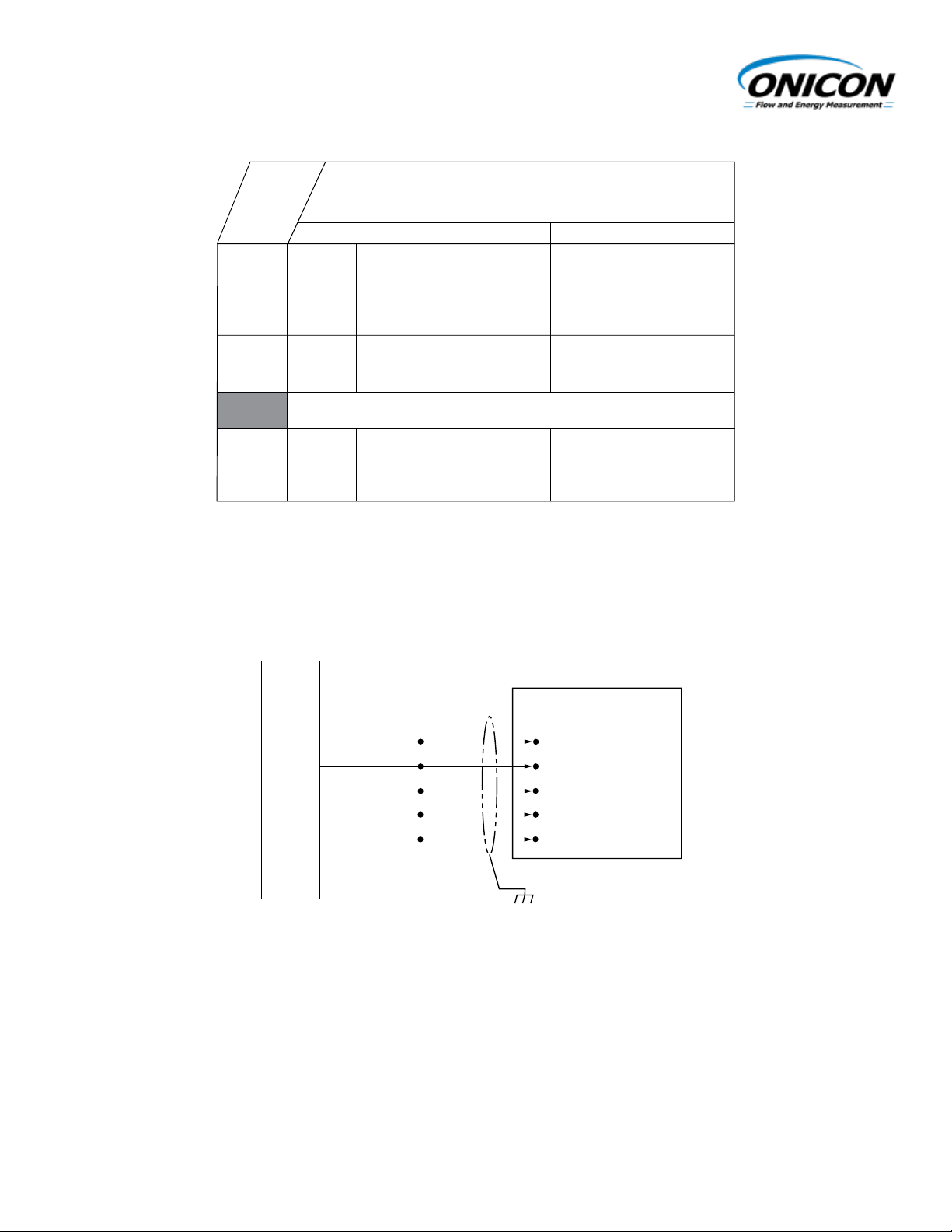
F-1XXX-00 WIRING DIAGRAM
Flow Meter Connections to ONICON Display or Btu Meter
F-1XXX-00 Wiring Diagram
Flow Meter Connections to ONICON Display or Btu Meter
RED
NOTES:
1. Black wire is common with the pipe (typically earth ground).
2. For ONICON display module or Btu meter, connect all wires provided. Refer to wiring
diagram provided with display or Btu meter
GREEN
BLACK
ORANGE
WHITE
ONICON Display
or BTU Meter
+ 24 V
FREQUENCY INPUT
GROUND
DRY CONTACT
DRY CONTACT
SHIELD
11451 Belcher Road South, Largo FL 33773 • USA • Tel +1 (727) 447-6140 • Fax +1 (727) 442-5699 • sales@onicon.com
Microprocessor Turbine Flow Meter Manual 04/18 - 2013-3 Page A-2
Page 31

ONICON
Flow and Energy Measurement
FLOW METER WIRING INFORMATION
User Connections for Models with Frequency Output
Models: F-1XXX-00
FLOW METER WIRING INFORMATION
User Connections for Models with Frequency Output
Models: F-1XXX-00
OUTPUT BOARD
SENSOR BOARD
MICRO B USB
(For configuration utility interface)
BOARD TO BOARD
CONNECTOR
DIAGNOSTIC LEDs
BLUE - STATUS
WHITE - TOP PULSES
ORANGE - BOTTOM PULSES
GREEN - AVERAGE PULSES
TOP TURBINE:
F-1200 ONLY
NOT USED
BOTTOM TURBINE:
F-1200 ONLY
NOT USED
DRY CONTACT
(ORANGE WIRE)
DRY CONTACT
(WHITE WIRE)
FREQUENCY OUTPUT
(GREEN WIRE)
COMMON GROUND
(BLACK WIRE)
+24V AC/DC SUPPLY (RED WIRE)
NOTES:
11451 Belcher Road South, Largo FL 33773 • USA • Tel +1 (727) 447-6140 • Fax +1 (727) 442-5699 • sales@onicon.com
Microprocessor Turbine Flow Meter Manual 04/18 - 2013-3 Page A-3
Page 32

FLOW METER WIRING INFORMATION
User Connections for Models with Non-Isolated Analog Outputs
Models: F-1XXX-10
ONICON
Flow and Energy Measurement
Wiring Information
WIRE COLOR CODE NOTES
(+) 24 ± 4 V AC/DC
supply voltage
RED
BLACK
(–) Common ground
(Common with pipe ground)
Connect to power supply
negative & analog input
ground
GREEN
(+) Frequency output signal:
0-15 V peak pulse
Required when meter
is connected to local
display or Btu meter
BLUE
(+) Analog signal
Jumper selectable
(4-20 mA / 0-10 V / 0-5 V)
BROWN
(-) Analog signal
SCALED PULSE OUTPUT
ORANGE
Dry Contact
WHITE
Dry Contact
Scaled Pulse Output
Connect to power supply
positive
F-1XXX-10
F-1XXXX-10 Wiring Diagram
Connections to a Control System (No Display or Btu Meter)
FLOW METER
√
√
√
√
√
√
√
ON
I
CON
Flow and Energy Measurement
!
FLOW METER WIRING INFORMATION
User Connections for Models with Analog Output
Models: F-1XXX-10
Wiring Information
F-1XXX-10
√
√
√
√
√
F-1XXX-10 WIRING DIAGRAM
Flow Meter Connections to ONICON Display or Btu Meter
√
√
BROWN
ORANGE
WIRE COLOR CODE NOTES
RED
BLACK
GREEN
BLUE
BROWN
ORANGE
WHITE
BLACK
BLUE
WHITE
(+) 24 ± 4 V AC/DC
supply voltage
(–) Common ground
(Common with pipe ground)
(+) Frequency output signal:
0-15 V peak pulse
(+) Analog signal
(-) Analog signal
Dry Contact
Dry Contact
RED
SCALED PULSE OUTPUT
Power
Source
+ 24 V
COM
+ ANALOG
- ANALOG
DRY CONTACT
DRY CONTACT
Connect to power supply
positive
Connect to power supply
negative & analog input
ground
Required when meter
is connected to local
display or Btu meter
Jumper selectable
(4-20 mA / 0-10 V / 0-5 V)
Scaled Pulse Output
Control System
NOTES:
1. Black wire is common with the pipe (typically earth ground).
2. For ONICON display module or Btu meter, connect all wires provided. Refer to wiring
diagram provided with display or Btu meter
CAUTION
This is NOT a “loop-powered” instrument. DO NOT connect power to any of the signal output
wires (blue, brown, green, orange or white)
11451 Belcher Road South, Largo FL 33773 • USA • Tel +1 (727) 447-6140 • Fax +1 (727) 442-5699 • sales@onicon.com
Microprocessor Turbine Flow Meter Manual 04/18 - 2013-3 Page A-4
Page 33

SENSOR BOARD
COMMON GROUND
(BLACK WIRE)
SCALED / ALARM (ORANGE WIRE)
+24V AC/DC SUPPLY (RED WIRE)
OUTPUT BOARD
DIAGNOSTIC LEDs
BLUE - STATUS
WHITE - TOP PULSES
ORANGE - BOTTOM PULSES
GREEN - AVERAGE PULSES
BOARD TO BOARD
CONNECTOR
SCALED / ALARM (WHITE WIRE)
FREQUENCY OUTPUT
(GREEN WIRE)
MICRO B USB
(For configuration utility interface)
BOTTOM TURBINE:
F-1200 ONLY
TOP TURBINE:
F-1200 ONLY
ANALOG OUTPUT TYPE JUMPER
(4-20 mA, 0-10 V, 0-5 V)
- ANALOG
(BROWN WIRE)
NOT USED
+ ANALOG
(BLUE WIRE)
NOT USED
NOT USED
ONICON
Flow and Energy Measurement
FLOW METER WIRING INFORMATION
User Connections for Models with Non-Isolated Analog Outputs
Models: F-1XXX-10
FLOW METER WIRING INFORMATION
User Connections for Models with Analog Output
Models: F-1XXX-10
NOTES:
11451 Belcher Road South, Largo FL 33773 • USA • Tel +1 (727) 447-6140 • Fax +1 (727) 442-5699 • sales@onicon.com
Microprocessor Turbine Flow Meter Manual 04/18 - 2013-3 Page A-5
Page 34

FLOW METER WIRING INFORMATION
User Connections for Models with Isolated Analog Outputs
Models: F-1XXX-11
ONICON
Flow and Energy Measurement
Wiring Information
WIRE COLOR CODE NOTES
(+) 24 ± 4 V AC/DC
supply voltage
RED
BLACK
(–) Common ground
(Common with pipe ground)
Connect to power supply
negative
GREEN
(+) Frequency output signal:
0-15 V peak pulse
Required when meter
is connected to local
display or BTU meter
BLUE
(+) Analog signal
Jumper selectable
(4-20 mA / 0-10 V / 0-5 V)
BROWN
(-) Analog signal
SCALED PULSE OUTPUT
ORANGE
Dry Contact
WHITE
Dry Contact
Scaled Pulse Output
Connect to power supply
positive
F-1XXX-11
F-1XXX-11 Wiring Diagram
Connections to a Control System (No Display or BTU Meter)
FLOW METER
√
√
√
√
√
√
√
!
FLOW METER WIRING INFORMATION
User Connections for Models with Isolated Analog Output
Models: F-1XXX-11
F-1XXX-11 WIRING DIAGRAM
F-1XXX-11
√
√
√
√
√
√
√
WIRE COLOR CODE NOTES
RED
BLACK
GREEN
BLUE
BROWN
ORANGE
WHITE
Wiring Information
(+) 24 ± 4 V AC/DC
supply voltage
(–) Common ground
(Common with pipe ground)
(+) Frequency output signal:
0-15 V peak pulse
(+) Analog signal
(-) Analog signal
SCALED PULSE OUTPUT
Dry Contact
Dry Contact
Connect to power supply
positive
Connect to power supply
negative
Required when meter
is connected to local
display or BTU meter
Jumper selectable
(4-20 mA / 0-10 V / 0-5 V)
Scaled Pulse Output
Flow Meter Connections to ONICON Display or Btu Meter
RED
BLACK
NOTES:
BLUE
BROWN
ORANGE
WHITE
1. Black wire is common with the pipe (typically earth ground).
2. For ONICON display module or Btu meter, connect all wires provided. Refer to wiring
diagram provided with display or Btu meter
CAUTION
Power
Source
+ 24 V
COM
Control System
+ ANALOG
- ANALOG
DRY CONTACT
DRY CONTACT
This is NOT a “loop-powered” instrument. DO NOT connect power to any of the signal output
wires (blue, brown, green, orange or white)
11451 Belcher Road South, Largo FL 33773 • USA • Tel +1 (727) 447-6140 • Fax +1 (727) 442-5699 • sales@onicon.com
Microprocessor Turbine Flow Meter Manual 04/18 - 2013-3 Page A-6
Page 35

ONICON
Flow and Energy Measurement
FLOW METER WIRING INFORMATION
User Connections for Models with Isolated Analog Outputs
Models: F-1XXX-11
FLOW METER WIRING INFORMATION
User Connections for Models with Isolated Analog Output
Models: F-1XXX-11
OUTPUT BOARD
*
ANALOG OUTPUT TYPE JUMPER
- ANALOG
(BROWN WIRE)
NOT USED
+ ANALOG
(BLUE WIRE)
MICRO B USB
(For configuration utility interface)
BOARD TO BOARD
CONNECTOR
DIAGNOSTIC LEDs
BLUE - STATUS
WHITE - TOP PULSES
ORANGE - BOTTOM PULSES
GREEN - AVERAGE PULSES
SENSOR BOARD
TOP TURBINE:
F-1200 ONLY
NOT USED
BOTTOM TURBINE:
F-1200 ONLY
NOT USED
DRY CONTACT
(ORANGE WIRE)
DRY CONTACT
(WHITE WIRE)
FREQUENCY OUTPUT
(GREEN WIRE)
COMMON GROUND
(BLACK WIRE)
+24V AC/DC SUPPLY (RED WIRE)
*
4-20 mA
0-5 V
0-10 V
NOTES:
11451 Belcher Road South, Largo FL 33773 • USA • Tel +1 (727) 447-6140 • Fax +1 (727) 442-5699 • sales@onicon.com
Microprocessor Turbine Flow Meter Manual 04/18 - 2013-3 Page A-7
Page 36

APPENDIX B
Installation Hardware Instructions
11451 Belcher Road South, Largo FL 33773 • USA • Tel +1 (727) 447-6140 • Fax +1 (727) 442-5699 • sales@onicon.com
Microprocessor Turbine Flow Meter Manual 04/18 - 2013-3 Page B-1
Page 37

2070
11451 Belcher Road South, Largo FL 33773 • USA • Tel +1 (727) 447-6140 • Fax +1 (727) 442-5699 • sales@onicon.com
Microprocessor Turbine Flow Meter Manual 04/18 - 2013-3 Page B-2
Page 38

2070
11451 Belcher Road South, Largo FL 33773 • USA • Tel +1 (727) 447-6140 • Fax +1 (727) 442-5699 • sales@onicon.com
Microprocessor Turbine Flow Meter Manual 04/18 - 2013-3 Page B-3
Page 39

2070
11451 Belcher Road South, Largo FL 33773 • USA • Tel +1 (727) 447-6140 • Fax +1 (727) 442-5699 • sales@onicon.com
Microprocessor Turbine Flow Meter Manual 04/18 - 2013-3 Page B-4
Page 40

2071
11451 Belcher Road South, Largo FL 33773 • USA • Tel +1 (727) 447-6140 • Fax +1 (727) 442-5699 • sales@onicon.com
Microprocessor Turbine Flow Meter Manual 04/18 - 2013-3 Page B-5
Page 41

2071
11451 Belcher Road South, Largo FL 33773 • USA • Tel +1 (727) 447-6140 • Fax +1 (727) 442-5699 • sales@onicon.com
Microprocessor Turbine Flow Meter Manual 04/18 - 2013-3 Page B-6
Page 42

APPENDIX C
Turbine Assembly Detail Drawings
11451 Belcher Road South, Largo FL 33773 • USA • Tel +1 (727) 447-6140 • Fax +1 (727) 442-5699 • sales@onicon.com
Microprocessor Turbine Flow Meter Manual 04/18 - 2013-3 Page C-1
Page 43

0098-2
04-18
TURBINE ASSEMBLY DETAILS FOR
UPPER SUPPOR
SAPPHIRE JEWEL
ON
I
CON
11451 Belcher Road South, Largo, FL 33773 • USA • Tel +1 (727) 447-6140 • Fax +1 (727) 442-5699
www.onicon.com • sales@onicon.com
Flow and Energy Measurement
Turbine must be free to slide
back and forth on the shaft with
at least .015” of movement.
TUNGSTEN CARBIDE
TURBINE SHAFT
Replace turbines in the same end-for-end relationship to the direction
of flow. (Mark one end of the turbine and the same end of the upper
support with a permanent felt tip marker)
After re-assembly, test the turbine for free rotation by gently blowing
on the turbine PARALLEL TO ITS SHAFT. The turbine must spin
freely and must have a minimum of .015” of free end play.
SAPPHIRE JEWEL RADIAL BEARINGS
If these bearings are removed from the turbine or
loosened at all, the flow meter must be returned to the
factory for recalibration or the turbine must be replaced.
ALL MODELS IN F-1100 SERIES
T
SUPPORT POST
2-56 Stainless, Philips Head Screws.
Clean philips head grooves with a sharp
instrument befor trying to loosen screws
in a meter which has been in service.
11451 Belcher Road South, Largo FL 33773 • USA • Tel +1 (727) 447-6140 • Fax +1 (727) 442-5699 • sales@onicon.com
Microprocessor Turbine Flow Meter Manual 04/18 - 2013-3 Page C-2
THRUST BEARINGS
TURBINE ROTOR
LOWER SUPPORT
Page 44

0099-2
04-18
UPPER SUPPORT
REMOVABLE
SUPPORT POST
SAPPHIRE JEWEL
THRUST BEARINGS
TURBINE
ROTORS
LOWER
SUPPORT
TUNGSTEN CARBIDE
TURBINE SHAFT
NON-REMOVABLE
SUPPORT POST
TURBINE ASSEMBLY DETAILS FOR
ALL MODELS IN F-1200 SERIES
ON
I
CON
Flow and Energy Measurement
11451 Belcher Road South, Largo, FL 33773 • USA • Tel +1 (727) 447-6140 • Fax +1 (727) 442-5699
www.onicon.com • sales@onicon.com
2-56 Stainless, Philips Head Screws.
Clean philips head grooves with a sharp
instrument befor trying to loosen screws
in a meter which has been in service.
Turbine must be free to slide
back and forth on the shaft with
at least .015” of movement.
Replace turbines in the same end-for-end
relationship to the direction of flow. (Mark
one end of the turbine and the same end
of the upper support with a permanent felt
tip marker)
After re-assembly, test the turbine for free
rotation by gently blowing on the turbine
PARALLEL TO ITS SHAFT. The turbine
must spin freely and must have a
minimum of .015” of free end play.
SAPPHIRE JEWEL RADIAL BEARINGS
If these bearings are removed from the turbine or
loosened at all, the flow meter must be returned to the
factory for recalibration or the turbine must be replaced.
11451 Belcher Road South, Largo FL 33773 • USA • Tel +1 (727) 447-6140 • Fax +1 (727) 442-5699 • sales@onicon.com
Microprocessor Turbine Flow Meter Manual 04/18 - 2013-3 Page C-3
 Loading...