

Johnson Controls METASYS TEC1100 Series, METASYS TEC1103, METASYS TEC1102, METASYS TEC1101 Technical Bulletin
Page 1

ECHNICAL BULLETIN
T
TEC1100 Series Thermostat
Issue Date August 8, 2002
Introduction
Description
In this document, Building Automation System (BAS) is a generic term
that refers to the Metasys® Network (Network Control Module [NCM] or
N30 series), Companion, and Facilitator® supervisory systems. When you
refer to system specific applications, use the specific system names.
The TEC1100 Series includes three nonprogrammable models:
single-stage (TEC1101), heat pump (TEC1102), and multistage
(TEC1103). The applications include furnace, air conditioner, heat pump,
and rooftop units. The TEC1100 incorporates fuzzy logic for precise
control in a thermostat type package.
All TEC1100s have Metasys N2 communication capability. This
communication allows the user to view and adjust parameters from a
remote workstation. It also provides information, such as outdoor air
temperature, to the TEC1100 units on the bus. The thermostat is easy to
operate and normally displays room temperature and mode of operation
using Cooling ( ) or Heating ( ) icons. When there is a call for cooling,
the Snowflake icon ( ) blinks. Likewise, during a call for heating, the
Flame icon ( ) blinks. When the temperature is satisfied, neither icon
blinks. In the Auto mode, both icons ( ) appear continuously when
satisfied. Light-Emitting Diodes (LEDs) on the top of TEC1102/1103
models use Binary Inputs (BIs) to indicate a clogged filter and external
service. A unique temperature alarm (BI 2) indicates that the zone
temperature has not been satisfied in 45 minutes.
© 2002Johnson Controls, Inc.
Part No. 24-8980-2, Rev. A www.johnsoncontrols.com
Code No. LIT-6363155
1
Page 2

Used to select Heating,
Auto, Off, or Emergency Heat
(E ht; available on TEC1102
only) mode of operation.
Cooling,
Used to run fan
continuously.
LEDs (TEC1102, TEC1103 only) indicate
system activity or problems (see Table 3).
75
Mode
Fan
Figure 1: TEC1100
Outdoor
Day/Night
Tec1100face
Used to display outside
temperature (optional).
Used to alternate between
day and night setpoints.
Timed Occupied mode when
keyboard locked.
Used to increase/decrease values
or change between C or F.°°
2 TEC1100 Series Thermostat Technical Bulletin
Page 3

Table 1: Specifications
Product TEC1101-1 Thermostat with N2 Bus, 1 Heat/1 Cool
TEC1102-1 Thermostat with N2 Bus, Heat Pump
TEC1103-1 Thermostat with N2 Bus, 2 Heat/2 Cool
Power Requirements
Relay Contact Rating
Binary Inputs
(LED 1, LED 2, CLK1)
Recommended Wire Size
Thermostat Measurement
Range
Outdoor Air Temperature
Indication Range
Control Range
Display Resolution
Minimum Deadband
°C/°F Conversion
N2 Communications
Ambient Operating
Conditions
Ambient Storage
Temperatures
Dimensions (H x W x D)
Shipping Weight
UL and cUL Listing
CE Compliance
FCC Compliance
The performance specifications are nominal and conform to acceptable industry standards. For application at
conditions beyond these specifications, consult the local Johnson Controls office. Johnson Controls, Inc. shall not
be liable for damages resulting from misapplication or misuse of its products.
This device complies with Class A Part 15 of the FCC rules. It was also verified to Class B. Operation is subject to
the following two conditions:
(1) This device may not cause harmful interference.
(2) This device must accept any interference received, including interference that may cause undesired operation.
This Class A digital apparatus meets all of the requirements of the Canadian Interference-Causing Equipment
Regulations. Cet appareil numerique de la classe A respecte toutes les exigences du Reglement sur le materiel
brouilleur du Canada.
20-30 VAC, 50-60 Hz, Class 2, 24 VAC nominal, 2.4 VA maximum not including
driven loads
Maximum Inductive: 1 ampere with surges to 3 amperes, 24 VAC Class 2
Maximum Resistive: 1 ampere, 24 VDC (2000 VA maximum for all outputs)
Minimum: 10 mA for 24 VAC circuit; 10 mA for a 24 VDC circuit
20-30 VAC or 22-30 VDC (Negative on 24 V [C] terminal). Switches at 2 VDC.
18 gauge at 100 feet/22 gauge at 20 feet
0 to 48°C (28 to 124°F)
-48 to 48°C (-50 to 124°F)
Heating: 5 to 30°C in 1° increments (38 to 88°F in 1° increments)
Cooling:16 to 40°C in 1° increments (60 to 88°F in 1° increments)
1°C (1°F)
1°C (2°F) (between heating and cooling)
20°C = 68°F, each Celsius degree above or below 20°C is 2°F
Isolated bidirectional, RS-485, 9600 baud
0 to 55°C (32 to 131°F); 5 to 90% RH noncondensing
-34 to 55°C (-30 to 131°F)
114.3 x 101.6 x 22.2 mm (4-1/2 x 4 x 7/8 in.)
0.171 kg (0.37 lb)
UL 873 Multiple Class 2 Device, UL94HB Plastic Enclosure
CISPR 22, Residential Class B, CE Directive (89/336/EEC, EN50081/1,
EN50082/2) Industrial and Residential
This equipment has been tested and found to comply with the limits for a Class A
digital device and verified to Class B pursuant to Part 15 of FCC Rules. These
limits are designed to provide reasonable protection against harmful interference
when this equipment is operated in a commercial environment. This equipment
generates, uses, and can radiate radio frequency energy and, if not installed and
used in accordance with the instruction manual, may cause harmful interference to
radio communications. Operation of this equipment in a residential area is likely to
cause harmful interference in which case the user is required to correct the
interference at his/her own expense.
TEC1100 Series Thermostat Technical Bulletin 3
Page 4

Table 2: TEC1100 Series Accessory Ordering Information
Item Product Code Number
Optional Accessories (includes mounting hardware)
Replacement Door for nonprogrammable thermostat (10/box) TEC10DOOR-NONPROG
Remote or Averaging Indoor Temperature Sensor SEN-500-1*
Outdoor Air Sensor with Outdoor Air Temperature Communication Module SEN-500-2**
Duct Mounted Outdoor Air Sensor with Outdoor Air Temperature
Communication Module
4- to 5-wire Conversion Module ACC-500-1***
Thermostat Wall Plate to conceal existing holes ACC-500-2****
Replacement Parts
Replacement Outdoor Air Temperature Communication Module SEN-500-603
Replacement Outdoor Air Temperature Sensor (includes mounting hardware) SEN-500-604
Replacement Duct Mount Outdoor Air Temperature Sensor
(includes mounting hardware)
Repair Parts
3 in. Sensor Probe (use with outdoor air sensor) SEN-500-601
8 in. Sensor Probe (use with duct-mount outdoor air sensor) SEN-500-602
* See SEN-500-1 Remote Indoor Temperature Sensor Product/Technical Bulletin (LIT-216504).
** See SEN-500-2 and SEN-500-3 Outdoor Air Temperature Sensors Product/Technical Bulletin
(LIT-216179).
*** See ACC-500-1 Conversion Module Product/Technical Bulletin (LIT-216500).
**** See ACC-500-2 Thermostat Wall Plate Product/Technical Bulletin (LIT-216502).
SEN-500-3**
SEN-500-605
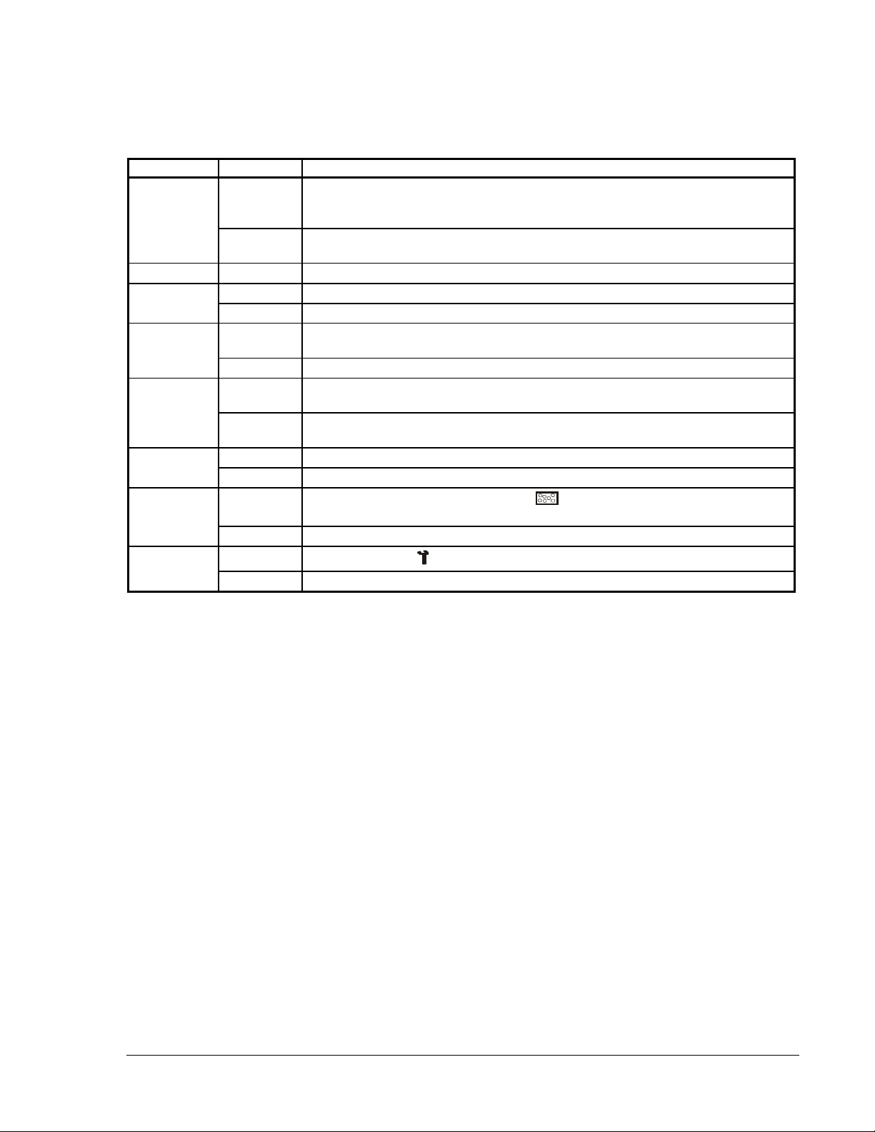
Table 3: Alarm Indicators (TEC1102 Heat Pump and TEC1103 Multistage)
LED Position Function BI
Right (
Center
(no symbol)
Left ( )
Temperature
Alarm (no LED)
Note: Either binary input (LED 1 or LED 2) can be used as a fan-proving switch for other applications.
Indicates a fault. Controlled by external switch on LED 2, which displays a
)
wrench icon and reports Change-of-State (COS) to the Metasys system and
causes the Network Dial Modem (NDM) to dial out.
(TEC1102 heat pump only). Indicates when Emergency (Auxiliary) heat
(E ht) is activated. Internally controlled. No COS.
Indicates filter needs changing. Controlled by external switch on LED 1, which
displays the filter icon and reports a COS to the Metasys system and causes
the NDM to dial out.
If the room temperature is more than 1°C (1°F) away from the setpoint after
45 minutes of operation, a COS occurs which causes the NDM to dial out.
Once the temperature reaches the setpoint, the alarm returns to normal.
1
N/A
3
2
4 TEC1100 Series Thermostat Technical Bulletin
Page 5

Table 4: Applications
Application Recommended Model
Fan Coil Unit
Heat Pump
Unit Heaters
Packaged Rooftop
Packaged Heating/Cooling
TEC1101-1
TEC1102-1
TEC1101-1
TEC1103-1 and Separate Economizer Package
(M130EAA-2 or equal in place of Stage 1). Refer to the
AD-DME1702-1 Direct Mount Economizer Controller
Technical Bulletin (LIT-6363020).
TEC1101-1 or TEC1103-1
Installation
Required Installation Tools
Mounting the TEC1100 Series Thermostat
The tools needed to install the TEC1100 Series thermostats are:
• drill
• 3/16 in. drill bit
• 1/8 in. and 1/4 in. flat-blade screwdrivers
• hammer
• marking pencil
• wire stripper
Note: Two plastic anchors with screws and the cover lock are included
with the TECs.
Mount the TEC1100 Series thermostat on an interior wall, approximately
1.5 m (5 ft) above the floor in a location of average temperature (72°F).
Do not mount the thermostat on outdoor walls or behind doors. Be sure to
install the thermostat away from direct sunlight or radiant heat, air
discharge grills, stairwells, or outdoor doors. Keep the thermostat away
from steam or water pipes, warm air stacks, areas with no airflow, or
sources of electrical interference.
To mount:
1. Lift the thermostat cover and insert a small coin into the slot located in
the bottom center of the thermostat case.
2. Twist 1/4 turn (Figure 2).
TEC1100 Series Thermostat Technical Bulletin 5
Page 6

Mount tec1100
Figure 2: Separating and Mounting the TEC1100
3. Grasp the base from the bottom two corners, and separate from the
thermostat.
4. Swing the thermostat out from the bottom, and lift up and out from the
base.
Note: When replacing an existing thermostat, use wire tags to identify
terminal designations.
5. Place the rectangular opening in the base over the equipment control
wires.
6. Use the base as a template, and mark the location of two mounting holes.
7. Drill two 5 mm (3/16 in.) holes at the marked locations.
8. Tap nylon anchors (included) flush to wall surface.
9. Place thermostat mounting holes over anchors, and screw the
thermostat into place using the included anchor screws (Figure 2).
10. Plug the hole in the wall to eliminate air drafts on the sensor with the
adhesive foam from the ACC-INSL-x Foam Pad Mounting Kit. If you
are not using this kit, use putty or duct tape to plug the hole.
Wiring the TEC1100 Series Thermostats
Follow these steps to wire the TECs:
1. Connect the wires from the existing system to the thermostat
terminals. Refer to Figure 4, Figure 6, and Figure 8 for wiring
diagrams.
2. Push any extra wire back into the wall. The wires must be flush to the
plastic base.
3. Plug the hole in the wall to eliminate air drafts on the sensor.
6 TEC1100 Series Thermostat Technical Bulletin
Page 7

Setting the DIP Switches
Select Dual Inline Package (DIP) switches to perform a variety of
different functions: fan runtime delay, keyboard disable, and multistage
heating or cooling.
Note: Before selecting a minimum On/Off time for the TEC1100 Series,
verify the equipment can tolerate the following hourly maximum
cycle rates: 7.5 cycles per hour when using 4-minute On/Off
(preferred for energy savings) or 15 cycles per hour when using
2-minute On/Off.
TEC1101 Single-Stage Wiring Configuration and DIP Switch Settings
Refer to Figure 3, Figure 5, and Figure 7 for DIP switch settings.
Table 5: TEC1101 Single-Stage DIP Switch Selections
DIP Switch Selection Description
1
2
3
* When DIP Switch 2 is on, you can only use the Day/Night mode button to select 1-hour override to occupied
setpoints if in Night mode. All other buttons are read-only. You can also view the N2 address.
On Allows 2-minute minimum On/Off time for heating or cooling equipment.
Off Allows 4-minute (preferred) minimum On/Off time for heating or cooling equipment.
On*
Off Unlocks the keyboard.
On In Heating mode, with a call for heat, the plenum temperature switch controls fan
Off Heating or Cooling mode allows the fan to operate immediately with a call for heat
Locks the keyboard, disabling buttons to prevent tampering. The Day/Night mode
button can select 1-hour override.
operation. However, Cooling mode allows the fan to operate immediately with a
call for cooling. The temperature switch is wired directly to the fan.
or cooling.
Heat/Cool: 4 Minute
(Minimum On/Off)
Fan Immediate
with Call for Heat
O
1
2
3
Heat/Cool: 2 Minute
(Minimum On/Off)
Keyboard LockedKeyboard Unlocked
Fan On with Plenum
Temperature Switch
CLK1
CLK2
RS2
RS1
RS+V
N2+
N2REF
TEC1101
Heating
Cooling
Fan
Power in
Common
W1
Y1
G
R
24V
24V(c)
Hcn2diwi
N
Figure 3: TEC1101 Single-Stage, Factory-Set DIP Switch Settings and
Wiring Configuration
TEC1100 Series Thermostat Technical Bulletin 7
Page 8

Table 6: TEC1101 Single-Stage Output Terminal Designations
Terminal Function
W1
Y1
G Energizes fan on call for heating or cooling or by pressing the Fan button.
R
24V
24V(c)
CLK1, CLK2
RS2, RS1, RS+V
N2+, N2-, REF
Energizes on call for heating.
Energizes on call for cooling.
Provides independent switching voltage.
Provides 24 VAC from equipment transformer.
Provides 24 VAC (common) from equipment transformer.
Connects remote clock/timer for alternate setpoints.
Connects outdoor air temperature or indoor remote sensors; refer to instructions included
with sensors.
Metasys N2 Bus connections
If the transformer (T2) is to power all of the loads, the yellow
pin jumper must be inserted (f actory position), which connects
R to 24 V. The jumper is located on the electronics board above
the relays. If a separate 24 V transformer (T1) is to be used,
it must be connected between R and 24 V(c), and the jumper
should not be connected between R and 24 V.
Jumper
Y1
Optional Plenum
Temperature Sensor
First St age
W1
Heat
First Stage
Cooling
G
Fan
R
T1 T2
24 V
24 V(c)
Figure 4: TEC1101 Single-Stage Wiring Schematic
CPN, FAC,
N2+
Electronics
Rs1
Remote
Sensor
(if used)
Metasys
or NCM
N2- REF
CLK1
Rs2
Clock/Timer
CLK2
Remote
(if used)
Thermostat
Equipment
8 TEC1100 Series Thermostat Technical Bulletin
Page 9
TEC1102 Heat Pump Wiring Configuration and DIP Switch Settings
Table 7: TEC1102 Heat Pump DIP Switch Selections
DIP Switch Selection Description
1
2
3
4
5
6
7
8
* When DIP Switch 4 is on, you can only use the Day/Night mode button to select 1-hour override to occupied
setpoints if in Night mode. All other buttons are read-only. You can also view the N2 address.
On Compressor/Auxiliary Interlocked: turns off the compressor when the auxiliary heat
(E ht) is on. The compressor remains off for 2 minutes after the auxiliary heat is
turned off to ensure that the heat pump coil has cooled.
Off Compressor/Auxiliary Normal: allows the compressor and auxiliary heat to be on
simultaneously.
Off Not used. Switch should remain in the Off position.
On Allows 2-minute minimum On/Off time for heating or cooling equipment.
Off Allows 4-minute minimum On/Off time for heating or cooling equipment (preferred).
On*
Off Unlocks the keyboard.
On Comfort: allows the Auxiliary Heat to be energized when the room temperature
Off Economy: minimizes the use of Auxiliary Heat. If the room temperature error is
On Allows multistage heating or cooling.
Off Allows single-stage heating or cooling.
On
Off No filter icon.
On
Off No wrench icon.
Locks the keyboard, disabling buttons to prevent tampering. Day/Night mode
button can select 1-hour override.
error is greater than 0.5°C (1°F) for 1.5 hours.
0.5°C (1°F) for 3 hours, auxiliary heat is energized.
Liquid Crystal Display (LCD) filter icon (
24 VAC.
LCD wrench icon (
) turns on with LED 2 contact closure to 24 VAC.
) turns on with LED 1 contact closure to
TEC1100 Series Thermostat Technical Bulletin 9
Page 10

Compressor/Auxiliary
g
Normal
Not Used
Heat/Cool: 4 Minute
(Minimum On/Off)
Keyboard Unlocked
Economy
Single-Stage
LED 1 Icon Off
LED 2 Icon Off
1
2
3
4
5
6
7
8
Compressor/Auxiliary
Interlocked
ON
Not Used
Heat/Cool: 2 Minute
(Minimum On/Off)
Keyboard Locked
Comfort
Multistage
LED 1 Icon
LED 2 Icon
(Wrench/ Fault)
(Filter)
2nd Stage Compressor
LED1
LED2
CLK1
CLK2
RS2
Rs1
RS+V
N2+
N2 REF
Auxiliary Heating
1st Stage Compressor
24 VAC Power In
24 VAC Common
Cool Reversing Valve
Heat Reversin
TEC1102
Fan
Figure 5: TEC1102 Heat Pump, Factory-Set DIP Switch Settings,
and Wiring Configuration
Table 8: TEC1102 Heat Pump Output Terminal Designations
Terminal Function
Y2
W1
Y1
G Energizes fan on call for heating or cooling or by pressing Fan button.
R
24V
24V(c)
LED 1, LED 2
CLK1, CLK2
RS2, RS1, RS+V
O
B
N2+, N2-, Ref
Energizes Compressor 2 on call for second stage heating or cooling.
Energizes auxiliary heat as third stage heating or emergency heat.
Energizes Compressor 1 on call for first stage heating or cooling.
Provides independent switching voltage.
Provides 24 VAC from equipment transformer.
Provides 24 VAC (common) from equipment transformer.
LED 1 or LED 2 contact closure to 24 VAC from remote switch.
Connects remote clock/timer for alternate setpoints.
Connects outdoor air temperature or indoor remote sensors; refer to instructions included
with sensors.
Energizes reversing valve in the Cooling mode.
Energizes reversing valve in the Heating mode.
N2 Bus
Valve
Y2
W1
Y1
G
R
24V
24V(C)
O
B
Hpn2wire
10 TEC1100 Series Thermostat Technical Bulletin
Page 11

If the transformer (T2) is to power all of the loads, the
yellow pin jumper must be inserted connecting
R to 24 V. The jumper is located on the electronics board
above the relays. If a separate 24 V transformer (T1) is to
be used, it must be connected between R and 24 V(c), and
the jumper should be removed between R and 24 V.
Jumper
Metasys
CPN, FAC,
NCM
N2-
N2+
Electronics
REF
W1
First St age
Compressor
Auxiliary
Heat
Y1 Y2 G O B R CLK1
Fan
Second
Stage
Compressor
Reverse
Val ve
Heating
Reverse
Val ve
Cooling
24 V
T1 T2
24 V(c)
LED1
LED2
Field Contact Switches
RS1
RS+V
Remote
Sensor
(if used)
RS2
Remote
Clock/Timer
(if used)
Figure 6: TEC1102 Heat Pump Wiring Schematic
CLK2
Thermostat
Equipment
Hpndiag
TEC1100 Series Thermostat Technical Bulletin 11
Page 12

TEC1103 Multistage Wiring Configuration and DIP Switch Settings
Table 9: TEC1103 Multistage DIP Switch Selections
DIP Switch Selection Description
1
2
3
4
5
6
* When DIP Switch 2 is on, you can only use the Day/Night mode button to select 1-hour override to occupied
setpoints if in Night mode. All other buttons are read-only. You can also view the N2 address.
Heat/Cool: 4 Minute
(Minimum On/Off)
Keyboard Unlocked
Single-Stage
LED 1 Icon Off
LED 2 Icon Off
On Allows 2-minute minimum On/Off time for heating or cooling equipment.
Off Allows 4-minute minimum On/Off time for heating or cooling equipment
(preferred).
On*
Locks the keyboard, disabling buttons to prevent tampering. The Day/Night
mode button can select 1-hour override.
Off Unlocks the keyboard.
Off Not used. Switch should remain in the Off position.
On Allows multistage heating or cooling.
Off Allows single-stage heating or cooling.
LED 1 Icon
On/Off
LED 2 Icon
On/Off
Not Used
Optional selection: LCD filter icon (
to 24 VAC.
Optional selection: LCD wrench icon (
closure to 24 VAC.
Heat/Cool: 2 Minute
1
2
3
4
5
6
ON
(Minimum On/Off)
Keyboard Locked
Not Used
Multistage
LED 1 Icon
LED 2 Icon
(Wrench/ Fault)
(Filter)
) comes on with LED 1 contact closure
) comes on with LED 2 contact
TEC1103
LED1
Second Stage Cooling
LED2
CLK1
CLK2
Rs1
RS2
RS+V
N2+
N2-
REF
Fan
24 VAC Power In
Common
Second Stage Heating
Y2
W1
Y1
G
R
24V
24V(c)
W2
Figure 7: TEC1103 Multistage Factory-Set DIP Switch Setting and
Wiring Configuration
12 TEC1100 Series Thermostat Technical Bulletin
Msn2wire
Page 13

Table 10: TEC1103 Multistage Output Terminal Designations
Terminal Function
W2
Y2
W1
Y1
G Energizes fan on call for heating or cooling or by pressing the Fan button.
R
24V
24V(c)
LED 1, LED 2
CLK1, CLK2
RS2, RS1, RS+V
N2+, N2-, REF
Energizes on call for second stage heat.
Energizes on call for second stage cooling.
Energizes on call for first stage heat.
Energizes on call for first stage cooling.
Independent switching voltage
24 VAC from equipment transformer
24 VAC (common) from equipment transformer
Input connection that energizes LED 1 or LED 2 from remote status device to 24 VAC
Connections for remote clock/timer for alternate setpoints
Connection for outdoor temperature sensor and/or indoor remote sensor option; refer to
instructions included with sensors.
Metasys N2 Bus connections
If the transformer (T2) is to power all of the loads, the
yellow pin jumper must be inserted, which connects
R to 24 V. The jumper is located on the electronics
board above the relays. If a separate 24 V transformer
(T1) is to be used, it must be connected between
R and 24 V(c), and the jumper should not be
connected between R and 24 V.
Jumper
24 V
R
G
Y2
Y1
W2
Second
Stage
Heat
Compressor
Second
Stage
Fan
T1
24 V(c)
T2
W1
First St age
Heat
First St age
Compressor
Figure 8: TEC1103 Multistage Wiring Schematic
Metasys
CPN, FAC,
NCM
N2+ REF
N2-
Electronics
LED2
Field Contact Switches
LED1
RS+V
RS1
Remote
Sensor
(if used)
RS2
CLK1
Clock/Timer
CLK2
Remote
(if used)
Msndiag
Thermostat
Equipment
Connecting the N2 Bus
To connect the N2 Bus:
1. Observe the polarity when connecting the N2 Bus wires to the
TEC1100.
Note: Each TEC has self-terminating End-of-Line (EOL) resistors.
However, one EOL resistor is needed at the BAS (two are
preferred at opposite ends).
2. Continue this process for each TEC1100 using the daisy-chain wiring
method (Figure 9).
TEC1100 Series Thermostat Technical Bulletin 13
Page 14

TEC1100
NCM300 Series
Port 1 - N2 Bus
NCM200 Series
(TB1 or Communicator
Terminal Board)
HRD
GRD
or
SFT
GRD
SFT
GRD
Connecting to N30 Series
To
Next
N2
Device
N2+
N2-
N2
REF
REF
N2
N2-
N2+
Figure 9: Connecting the TEC1100 to an NCM
DS1
DS2
DS3
Tec 1100n30
To
Next
N2
Device
N2
REF
N2-
N2+
N2+
N2REF
TEC1100
N2+
N2-
N2 REF
N2+
N2-
REF
N30
24 VAC
N2+
N2REF
S
Tec 1100 ncm
Figure 10: Connecting the TEC1100 to the N30 Series
Connecting to the Companion/ Facilitator System
TEC1100
N2+
N2REF
N2+
N2REF
Figure 11: Connecting the TEC1100 to the
Companion/Facilitator System
14 TEC1100 Series Thermostat Technical Bulletin
Companion/Facilitator
Transformer
24VAC
GND
24VAC
N2+
N2-
REF
N2 Bus
Connector
Tec 1100 cpn
Page 15

Connecting to Network Display Module (NDM)
NDM
TEC1100
REF
N2N2+
N2+
N2-
REF
Figure 12: Connecting the TEC1100 to the NDM
N2 ADDRESS
F
F
O
N2 TRANSMIT
N2 RECEIVE
OUT
IN
REF
N2N2+
1
2
4
8
16
32
64
128
N2 END
OF LINE
NU-NDM101-0
REV - M9426
POWER
9-12 VAC/D C
0.5A
©
1995
4100/D01 /03
tec1100ndm
Setting the N2 Address
N2 Device Mapping
To set the N2 Address:
1. Push the Fan and Mode buttons simultaneously for 10 seconds after
the machine is turned on. The lower section of the display shows the
current N2 address.
2. Push the ∨ or ∧ buttons to change the address (1-253). Map the
TEC1100 into CPN/FAC/NCM/N30 series as a vendor device (VND).
3. Push any button to exit this mode, or wait 5 seconds and the TEC
automatically returns to normal operation.
Note: You can lock the keyboard using the DIP switch to prevent address
change, however, this disables access to other functions except
temporary occupancy.
When adding the TEC to the Metasys system (Person-Machine Interface
[PMI] and Companion system), you must define the TEC1100 as a Vendor
Device (VND). For the NCM, do not direct map any points. Run control
of these points through the Control System (CS) object only.
Note: For the TEC110x-0, do not use the Adjust command with the
Companion/Facilitator (CPN/FAC) system. This command is not
supported. The TEC110x-0 responds with an offline message but
continues to operate normally.
TEC1100 Series Thermostat Technical Bulletin 15
Page 16

Table 11: N2 Bus Objects
Point Name TEC
Point
Type/
Addr.
Room Temp
Outdoor Temp
Heating SP
Cooling SP
a
a
a
ADI-1 N2 AI
ADI-2 N2 AI
ADI-3 N2 AO
ADI-4 N2 AOAOCSAD ADI4 1 to 47°C (29 to 99°F)
N30
(CPN/
FAC)
Object
Type
d
(AI)
d
(AI)
(AO)
BAS
Override Range TEC
Model
Point
Type
CSAD ADI1 0 to 48°C
(28 to 124°F)
CSAD ADI2 -48 to 48°C
(-54 to 124°F)
CSAD ADI3 1 to 47°C (29 to 99°F)
1101
TEC
1102
TEC
1103
♦♦♦
♦♦♦
♦♦♦
♦♦♦
Setback Heating SP
a
ADI-5 N2 AO
CSAD ADI5 1 to 47°C (29 to 99°F)
♦♦♦
(AO)
Setback Cooling
a
SP
Minimum Heat SP
ADI-6
a
ADI-7 N2 AO
N2 AO
(AO)
CSAD ADI6 1 to 47°C (29 to 99°F)
CSAD ADI7 1 to 47°C (29 to 99°F)
♦♦♦
♦♦♦
(AO)
Maximum Heat SP
a
ADI-8 N2 AO
CSAD ADI8 1 to 47°C (29 to 99°F)
♦♦♦
(AO)
Minimum Cool SP
a
ADI-9 N2 AO
CSAD ADI9 1 to 47°C (29 to 99°F)
♦♦♦
(AO)
Maximum Cool SP
a
Fan
a
Mode
Occupancy
W1 State
a
ADI-10 N2 AO
(AO)
BD-1
N2 BO
(BO)
BD-2 N2
MSO
(AO)
a
BD-3
N2 BO
(BO)
BD-4 N2 BI
CSAD
1 to 47°C (29 to 99°F)
♦♦♦
ADI10
CSBD BD1
0 = Off/Auto,
♦♦♦
1 = On/MAN
CSMS BD2 0 = Off 1= Cool,
ef
2 = Heat, 3= Auto,
4 = E Ht (Aux Heat)
CSBD BD3
0 = Unoccupied,
Mode
f
0-3
Mode
0-4
♦♦♦
1 = Occupied
CSBD BD4 0 = Off, 1 = On Heat 1 E Heat Heat 1
Mode
0-3
(BI)
W2 State or Heat
Pump ‘O/B’
BD-5 N2 BI
(BI)
CSBD BD5 0 = Off, 1 = On Heat
Pump
Heat 2
O/B
Continued on next page . . .
Notes:
a Commandable
c On the Metasys NCM system, map BD9 Temp Units Mode as a Binary Output (BO) object in a Control System
(CS) object with Autorestore and Local Control set.
d AIs are commandable in the Companion/Facilitator system.
e The Multiple Command Output (MCO) object is used to schedule multiple Multi-State Objects (MSOs).
f When defining the N2 MSO object, select TEC Mode from the States Text Menu. Type 5 in the Number of
States field if you’re using the TEC1102 Heat Pump model, or type 4 for any other model. Mode 4, or
Emergency (Auxiliary) Heat (displayed as E ht), is only available on the TEC1102 Heat Pump model.
The Controller Point Type is the fixed point definition inside the controller. The CPN/FAC point is the software point
definition inside of the Companion software. The BAS Model Point type is the definition inside the model file. An
NCM CS object must be used to retrieve the data.
Control of the Analog Data (AD) objects is the last command received is the one that controls the thermostat. For
example, if the Metasys system sends a Night override, but the occupant selects Day mode, the TEC goes into Day
mode.
16 TEC1100 Series Thermostat Technical Bulletin
Page 17

Point Name
(Cont.)
TEC
Point
Type/
Addr.
N30
(CPN/
FAC)
Object
BAS
Model
Point
Type
Override Range TEC
1101
TEC
1102
TEC
1103
Type
Y1 State
Y2 State
G State – Fan
Temp Units
Wrench BI
Temp Alarm
Filter
Notes:
a Commandable
b Can be a COS alarm to the BAS or NDM to initiate a dial-out.
c On the Metasys NCM system, map BD9 Temp Units Mode as a Binary Output (BO) object in a Control System
(CS) object with Autorestore and Local Control set.
The Controller Point Type is the fixed point definition inside the controller. The CPN/FAC point is the software point
definition inside the Companion software. The BAS Model Point type is the definition inside the model file. An NCM
CS object must be used to retrieve the data.
Control of the Analog Data (AD) objects is the last command received is the one that controls the thermostat. For
example, if the Metasys system sends a Night override, but the occupant selects Day mode, the TEC goes into Day
mode.
ac
b
b
b
BD-6 N2 BI
(BI)
BD-7 N2 BI
(BI)
BD-8 N2 BI
(BI)
BD-9 N2 BO
(BO)
BI-1
BI-2 N2 BI
BI-3 N2 BI
N2 BI
(BI)
(BI)
(BI)
CSBD BD6 0 = Off, 1 = On Cool 1 Comp 1 Cool 1
CSBD BD7 0 = Off, 1 = On Comp 2 Cool 2
CSBD BD8 0 = Off, 1 = On
CSBD BD9 0 = °C, 1 = °F
CSBI BI1 0 = Normal, 1 = Alarm
CSBI BI2 0 = Normal, 1 = Alarm
CSBI BI3 0 = Normal, 1 = Alarm
♦♦♦
♦♦♦
♦♦
♦♦♦
♦♦
Installing the Thermostat Cover Lock
To install the thermostat cover lock:
1. Place the ends of the lock piece (included with unit) under the lock
pins extending from the bottom of the mounted base. The tab in the
middle of the lock piece extends downward from the mounted base
(Figure 13).
2. Press the lock piece up and into the base while gently prying open the
thermostat to release the lock. Use caution to avoid cracking the
thermostat base or cover.
TEC1100 Series Thermostat Technical Bulletin 17
Page 18

Plastic
Lock Pins
Thermostat
Base
Snap
plastic lock
piece into place.
Hinged
Tab s
Insloc
Figure 13: Installing the Thermostat Cover Lock
Reattaching the Thermostat
To reattach the thermostat:
1. Position the thermostat inside the cover, and attach on the hinged tabs
located at the top of the base.
2. Swing the thermostat and cover down.
3. Press on the bottom center edge until the plastic lock snaps in place
(Figure 13).
18 TEC1100 Series Thermostat Technical Bulletin
Page 19

TEC1100 Features
Table 12: TEC1100 Features
Feature Description
Control
Algorithm
Clock Terminals
CLK1 - CLK2
Temporary
Occupied with
Keyboard Lock
Remote Sensor
Outdoor/Duct
Temperature
Sensor
Power Failures or
N2 Failures
N2 Dial Module
(NDM)
N2 Address Push Fan and Mode buttons simultaneously and hold for 10 seconds to view address.
Over time, the TEC1100 learns how long it takes the system to meet the load. If the system
can change the room temperature quickly, the TEC1100 allows the thermostat to drift further
from setpoint before starting the equipment. If the system takes a longer period of time to
change the room temperature, the TEC1100 does not allow the temperature to drift as far
from setpoint. The TEC1100 also takes into account the minimum On/Off times.
The 2-minute On/Off time allows the equipment to cycle more frequently at smaller
differentials than the 4-minute On/Off time.
For multistage applications, the TEC1100 does not bring on the next stage of cooling or
heating if it knows that the system can change the temperature by 6° in one hour or 1° in
10 minutes. To verify thermostat operation, force the next stage on by changing the setpoint
by more than 2° (see the Verifying Proper Thermostat Operation section).
The TEC1100 thermostat accepts a contact closure for a clock/timer to allow the use of
alternate or setback heating and cooling setpoints in place of a BAS.
When the contact is open, the Day icon (
setpoint. When the contact is closed, the Night icon (
to the night setpoint. Pressing the Day/Night button when the thermostat is in Night mode
switches the thermostat to Day mode, even if a clock/timer is used. The Clock (CLK)
contacts on the thermostat are in parallel with the thermostat Day/Night button and changes
to the next command given by the clock. Therefore, if the thermostat is in Night mode
(contacts closed) and the thermostat is switched to the Day mode from the front panel, then
at the next clock control time, the thermostat stays in the Day mode. When the contacts
close again the following night, the thermostat switches to night setpoints.
When in Night mode, select this feature by pushing Day/Night button to put TEC1100 in
1-hour timed override to occupied setpoints.
When using a remote sensor (SEN-500-1), the TEC1100 internal sensor is disabled. If two to
six remote sensors are connected, then they can be used for temperature averaging. See the
SEN-500-1 Remote Indoor Temperature Sensor Product/Technical Bulletin (LIT-216504) for
more information.
There are two separate analog inputs on the TEC1100, which are the room sensor and a
duct or outdoor air sensor on a slave bus. The duct temperature appears when the Outdoor
button is pushed. On the TEC1101 and TEC1103, the outdoor/duct sensor is simply a
monitor of temperature. On the TEC1102, the Outdoor temperature provides a low
temperature lockout (see Displaying Outdoor/Duct Air Temperature under the
Commissioning section later in this document). Both of these can be displayed on the LCD or
at the Metasys system. The Outdoor temperature can be a global N2 Override from a single
sensor. For wiring information, refer to the SEN-500-2 and SEN-500-3 Outdoor Air
Temperature Sensors Product/Technical Bulletin (LIT-216179).
In the event of a power failure, or 10 minutes after an N2 communication loss, the thermostat
retains the last setpoints. When power is restored, it remains in normal operation and does
not require resetting. If power was lost when the thermostat was in Night mode, it returns to
Day mode.
There are three binary input points to cause a COS that triggers the remote NDM to dial out.
Binary Inputs 1 and 3 (wrench and filter) are general purpose inputs powered by 24 VAC or
22-30 VDC. Binary Input 2 is the Temperature Alarm binary data point that causes a COS if
the zone temperature is moving away from the setpoint after 45 minutes. The COSs operate
regardless of which stages are on. Overrides remain after the NDM hangs up.
) appears, and the thermostat adjusts to the day
) appears, and the thermostat adjusts
TEC1100 Series Thermostat Technical Bulletin 19
Page 20
Commissioning
Verifying Proper Thermostat Operation
Selecting an Operation Mode
To verify proper thermostat operation:
1. Press the Mode button to select the Heating or Cooling mode.
2. Press the ∨ or ∧ buttons to raise the setpoint above or below the
current ambient temperature. The thermostat calls for either heating or
cooling.
To energize each stage of heating quickly, set the heating setpoint 2°F
above the present room temperature. Wait for the Heat icon displayed on
the Liquid Crystal Display (LCD). For example, if the room temperature is
70°F, set the heating setpoint to 72°F. The first stage of heating should
energize. Once the Heat icon is off, readjust the setpoint 2°F above the last
setpoint (for example, 74°F). When the Heat icon is off, adjust the setpoint
2°F higher (76°F), to energize the auxiliary heat (TEC1102 model only).
Press the Mode button to select from the modes listed in Table 13.
Table 13: TEC1100 Series Thermostat Modes
Mode Description
COOL
HEAT
E Ht
Auto
OFF
Note: The thermostat never allows less than 1°C (2°F) difference between cooling and
heating setpoints. Use caution when using the OFF mode in extremely cold weather.
When the Snowflake icon (
thermostat is in the Cooling mode. When the thermostat is calling for
cooling, the snowflake blinks.
When the Flame icon (
thermostat is in the Heating mode. When the thermostat is calling for
heating, the flame blinks.
When the Flame icon (
thermostat operates using the emergency heat with the compressor locked
out (TEC1102 Heat Pump only).
When the Snowflake (
displayed, the thermostat automatically changes over between heating and
cooling.
When OFF is displayed, the equipment does not operate.
) and the word COOL are displayed, the
) and the word HEAT are displayed, the
) and E Ht (emergency heat) are displayed, the
) and the Flame ( ) icons and the word Auto are
20 TEC1100 Series Thermostat Technical Bulletin
Page 21

Selecting a Temperature Scale
Press the ∨ and ∧ buttons simultaneously to alternate between Celsius and
Fahrenheit display. This does not affect the BAS display. For example,
hotel room temperature can be displayed in °F on the Companion system,
but a hotel guest can switch the local display to °C. If power loss occurs,
the TEC reverts to the last network command (in this example, °F).
Selecting Fan Operation
Displaying Outdoor/Duct Air Temperature
Setting the Electronic Outdoor High and Low Balance Points
For continuous operation, press the Fan button and the Fan icon ( )
appears. If the Fan button has not been selected, the fan operates
automatically on a call for heat or cool (no fan symbol appears).
When an outdoor or duct temperature sensor (order separately) is
connected to the TEC1100 thermostat or if the outdoor air temperature is
available from the N2 network, press the Outdoor button. The
temperature is displayed along with corresponding icons ( ). The
Metasys BAS can display the Outdoor Duct Air temperature when mapped
back. The TEC1102 uses the outdoor air sensor or N2 value for low
temperature compressor lockout and high temperature heating lockout.
When there is no N2 command and the sensor option is not connected, the
thermostat displays --- when the button is pushed.
To use outdoor air lockout, you must set the high and low balance points.
Any outdoor temperature above the high balance point locks out the
auxiliary heat, and any outdoor temperature below the high balance point
allows the auxiliary heat to run when called for by the thermostat.
Similarly, any outdoor temperature below the low balance point locks out
the compressor, and any temperature above the low balance point allows
the compressor to run when called for by the thermostat. Both balance
points can be set from -48 to 50°C (-55 to 125°F).
Note: To set the high and low balance points, an outdoor sensor must be
attached to the unit.
To set the high and low balance points for outdoor air lockout:
1. Press and hold the Outdoor button, then press the Mode button. HibP
appears in the display, meaning high balance point, along with the
current balance setpoint.
2. Press the ∨ and ∧ buttons to set the high balance point temperature.
3. Press the Outdoor button. LobP appears in the display, meaning low
balance point, along with the current balance setpoint.
4. Press the ∨ and ∧ buttons to set the low balance point temperature.
5. Press the Mode button to resume operation.
TEC1100 Series Thermostat Technical Bulletin 21
Page 22

Selecting Day or
Night Mode (
)
When the TEC1100 Series thermostat is first installed, or after a power
loss, the display shows the Day icon ( ) and the temperature. Once the
BAS overrides the Day/Night mode, the corresponding symbol appears.
To select Day or Night mode:
• use BAS to schedule the Day/Night modes through the occupancy
binary data point, or
• press the Day/Night icon ( ), or
• install a time clock using the CLK1 and CLK2 terminals, to activate
the thermostat’s Night mode
Sensor Calibration
Setting the Thermostat Setpoints
The internal and remote sensors can be calibrated to eliminate wire
resistance errors or to match another reference.
To calibrate the thermostat:
1. Press and hold the Fan button for 10 seconds.
2. Adjust the temperature with the ∨ and ∧ buttons. The temperature is
shown on the lower display to the hundredth place. For example,
72°F on the large display is shown as 72 13.
3. Press the Fan button again to accept the reading.
To set the thermostat setpoints:
1. Press the Day/Night button until the Day icon ( ) appears.
2. Set the mode to Cool ( ).
3. Select the desired temperature for equipment to maintain during the
day while in the Cooling mode, using the ∨ or ∧ buttons. The cooling
setpoint range is 16 to 40°C (60 to 88°F).
4. Set the mode to Heat ( ).
5. Select the desired temperature for equipment to maintain during the
day while in the Heating mode using the ∨ or ∧ buttons. The heating
setpoint range is 5 to 30°C (38 to 88°F).
6. Press the Day/Night button until the Night icon ( ) appears.
7. Repeat Steps 2 through 5 for the night setpoints.
8. Verify N2 address is not inadvertently changed.
Keyboard Locked
The Keyboard Lock is selected by setting the DIP switch. The Locked
icon ( ) appears on the display when any button is pressed. Use keyboard
lock to put the TEC into occupied setpoints for one hour. All the
TEC values may be overridden from the Operator Workstation (OWS).
22 TEC1100 Series Thermostat Technical Bulletin
Page 23

Troubleshooting
N2 Bus
Configuration
See Table 14 if the TEC1100 thermostat does not function properly during
N2 Bus Configuration.
Troubleshooting
Table 14: N2 Bus Configuration Troubleshooting
Error/Trouble
Condition
TEC1100 cycles online
and offline.
TEC1100 does not come
online.
Entire N2 Bus is offline.
Possible Causes Solution
Two or more controllers have the
same address.
There are ‘Y’ or ‘T’ taps or the
repeater lost power or is wired
incorrectly.
Two or more controllers have the
same address.
N2 Bus contains too many devices. The maximum of N2 devices allowed on the
TEC1100 does not have power. Apply power to the TEC1100.
N2 cable runs are broken. Locate and correct the wiring.
Device type is incorrect. TEC1100 address must be VND device type.
EOL jumpers on MM-CVT101 or NCM
are not installed.
MM-CVT101 is not plugged into
Personal Computer (PC) or
120 VAC source.
Wiring near the BAS is broken. Repair the wiring.
No point mapping entered Define the BAS database.
Change each duplicate address to a unique
number.
Refer to the N2 Communications Bus
Technical Bulletin (LIT-636018).
Change each duplicate address to a unique
number.
N2 Bus is as follows: 100 devices per NCM,
32 devices per N30, 32 devices per N31,
150 devices per the Companion/Facilitator
system.
Install EOL jumpers properly.
Plug MM-CVT101 into PC or plug it into a
120 VAC source.
TEC1100 Series Thermostat Technical Bulletin 23
Page 24
Occupant Hot/Cold Complaints Troubleshooting
Zone temperature control problems, usually reported as occupant hot/cold
complaints, can have causes ranging from the building or mechanical
system to the control components. Table 15 helps locate the cause of zone
temperature control problems with TEC1100 Series thermostats.
Table 15: TEC1100 Series Thermostat Troubleshooting
Symptom Possible Cause Corrective Action
No display/faint
display
Keyboard
inoperative.
Thermostat does
not call for heat.
Thermostat does
not call for cooling.
Fan does not turn
on with the system.
“AC” is flashing in
the LCD.
LCD shows missing
or extra segments.
-55 appears when
Outdoor button is
pushed.
“-- -- --” appears.
Supply voltage incorrect. Use a voltmeter to check the voltage between the 24 V and
24 V(c) terminals. Voltage should be between 20-30 VAC.
If voltage is less than 20 VAC, disconnect the thermostat
and check the voltage between 24 V and the other system
wires; see possible causes below. If voltage is greater than
30 VAC, troubleshoot the power source and replace the
thermostat.
System transformer weak
or overloaded.
Thermostat damaged
because system voltage
was greater than 30 VAC.
Keyboard is locked. Switch the keyboard DIP switch to the unlocked position.
Short cycle delay still in
progress
Thermostat setpoint is
satisfied.
Short cycle delay still in
progress
Thermostat setpoint is
satisfied.
Fan failure Place a wire between Terminals R and G. Fan should turn
Plenum temperature switch
failure
20-30 VAC absent from
R and C terminals
LCD failure Replace the unit.
The sensor wire is open
inside the outdoor/duct
sensor module.
Miswired outdoor air sensor
or N2 override missing
Check and/or replace with a suitable 24 V transformer.
Replace with new thermostat, and ensure new thermostat
is isolated from the system using suitable relays and a
transformer of the proper rating.
Wait 2 to 4 minutes for the equipment short cycle
protection to complete.
Press Mode button until thermostat is in heat mode. Raise
the heating setpoint using the ∧ button.
Wait 2 to 4 minutes for the equipment short cycle
protection to complete.
Lower the cooling setpoint using the ∨ button.
on. If it does not, troubleshoot the fan system. If fan contact
does not energize, replace the thermostat.
In Heat mode with a separate plenum switch, the fan does
not turn on until the plenum is up to its preset temperature.
Replace the plenum switch.
Using a voltmeter, measure voltage between the 24 V and
24 V(c) terminals. If the reading is less than 20 VAC, check
system transformer. If the voltage is between 20 and
30 VAC, replace the thermostat.
Repair or replace the sensor element (SEN-500-604 or
SEN-500-605; see the SEN-500-2 and SEN-500-3 Outdoor
Air Temperature Sensors Product/Technical Bulletin
[LIT-216179] for more information).
Add the sensor. Check the N2 command.
Controls Group
507 E. Michigan Street
P.O. Box 423 www.johnsoncontrols.com
Milwaukee, WI 53201 Printed in U.S.A.
24 TEC1100 Series Thermostat Technical Bulletin
 Loading...