

Page 1
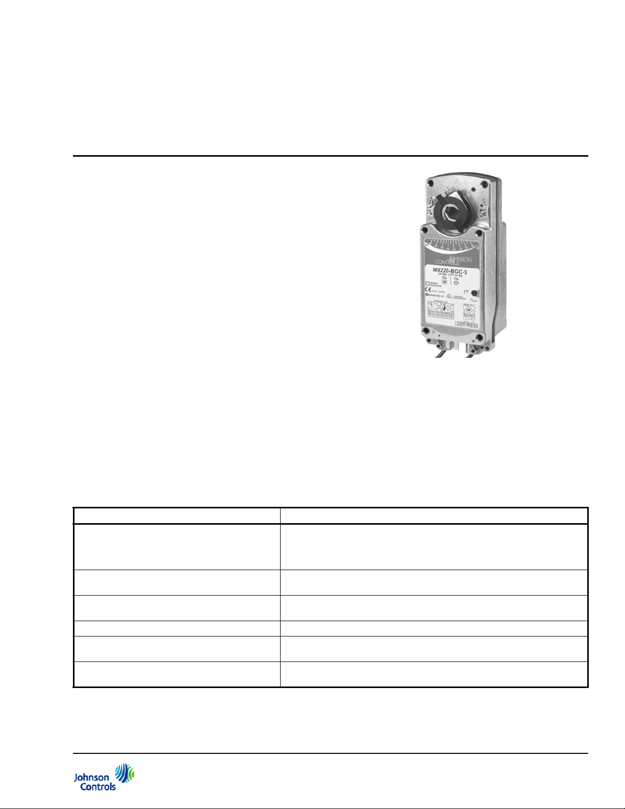
Figure 1: M9220-xxx-3 Electric Spring Return
Actuator
M9220-xxx-3 Electric Spring Return Actuators
Product Bulletin
Refer to the QuickLIT Web site for the most up-to-date version of this document.
The M9220-xxx-3 Actuators are direct mount, spring
return electric actuators that operate on these available
power options:
• AC 24 V at 50/60 Hz or DC 24 V (AGx, BGx, GGx,
HGx)
• AC 120 V at 60 Hz (BAx)
• AC 230 V at 50/60 Hz (BDx)
These bidirectional actuators do not require a damper
linkage and are easily installed on dampers with 1/2 to
3/4 in. or 12 to 19 mm round shafts, or on dampers with
3/8 and 1/2 in. or 10, 12, and 14 mm square shafts,
using the standard shaft clamp inclu ded with the
actuator. An optional M9220-600 Jackshaft Coupler Kit
is available for 3/4 to 1-1/16 in. or 19 to 27 mm round
shafts, or 5/8 and 3/4 in. or 16, 18, and 19 mm square
shafts.
Code No. LIT-12011057
Issued November 19, 2012
Supersedes November 8, 2012
A single M9220-xxx-3 Electric Spring Return Actuator
provides a running and spring return torque of 177 lb·in
(20 N·m). Two or three models mounted in tandem
deliver twice or triple the torque (354 lb·in [40 N·m] or
531 lb·in [60 N·m]). Integral line voltage auxiliary
switches are available on the xxC models to indicate
end-stop position or to perform switching functions
within the selected rotation range.
Table 1: Features and Benefits (Part 1 of 2)
Features Benefits
Available Torques of 177 lb·in (20 N·m) for
Single Actuators, 354 lb·in (40 N·m) for Two
Models, and 531 lb·in (60 N·m) for Three
Models Mounted in Tandem
Reversible Mounting Design Simplifies installation and enables the actuator to spring return in either
Electronic Stall Detection throughout Entire
Rotation Range
Removable Coupler Adapts to a shorter damper shaft.
Integral 48 in. (1.2 m) Halogen-Free Cables
with Colored and Numbered Conductors
Integral Auxiliary Switches (xxC Models) Provide one fixed and one adjustable switch point with line voltage
Offer a selection that is most suitable for the application.
direction.
Extends the life of the actuator by deactivating the actuator motor when an
overload condition is detected.
Simplify field wiring.
capability.
M9220-xxx-3 Electric Sp ring Return Actuators Product Bulletin 1
Page 2
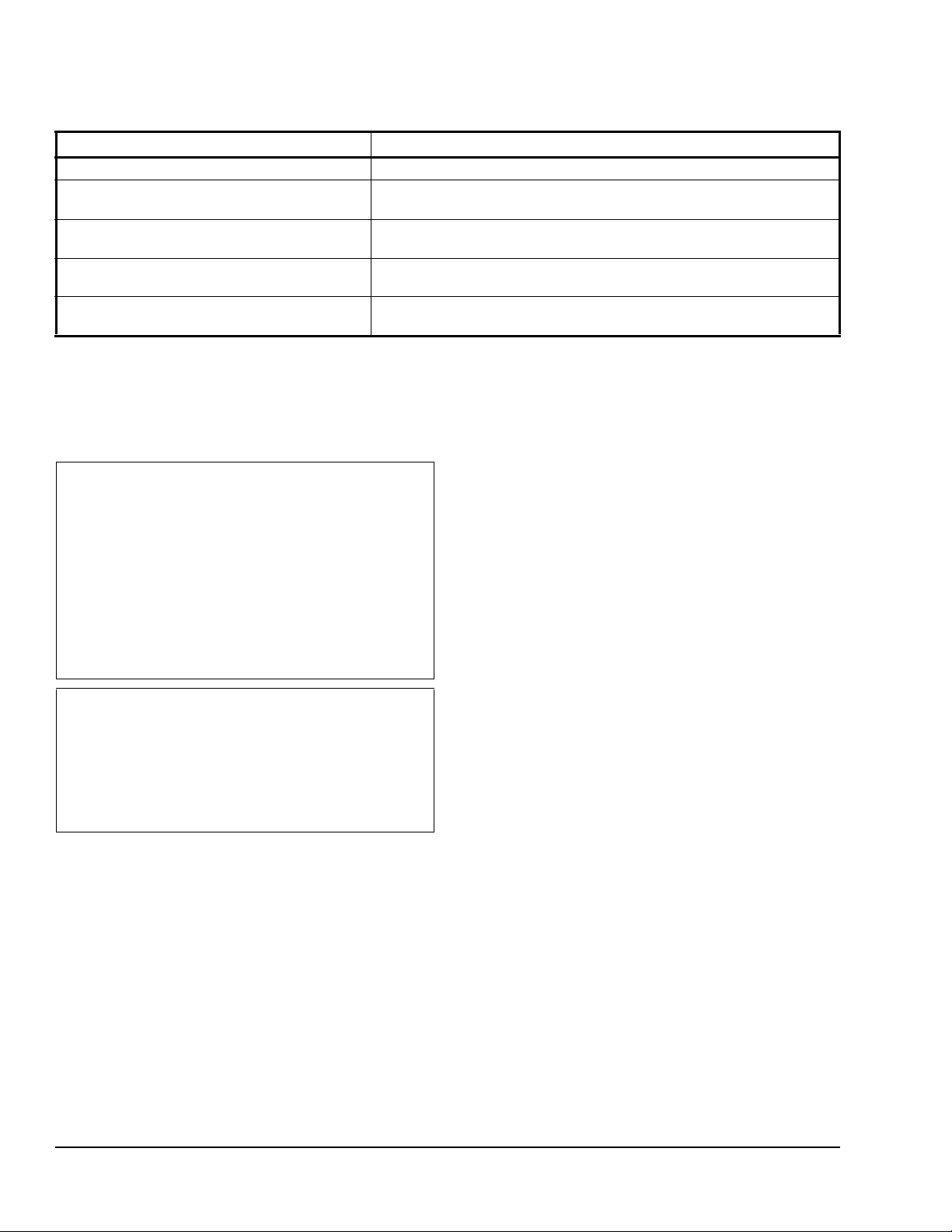
Table 1: Features and Benefits (Part 2 of 2)
Features Benefits
NEMA 2 (IP54) Rated Aluminum Enclosure Protects the internal components of the actuator from dirt and moisture.
Easy-to-Use Locking Manual Override with
Auto Release and Crank Storage
Integral Connectors for 3/8 in. (10 mm)
Flexible Metal Conduit
Override Control
(Proportional Models Only)
Microprocessor-Controlled Brushless
DC Motor (-AGx, -GGx, and -HGx Types)
Allows for manual positioning of the actuator hub.
Simplify installation and field wiring.
Supports control system override applications through field wiring.
Provides constant run-time independent of torque.
Product Overview
The M9220-xxx-3 Electric Spring Return Actuators
provide reliable control of dampers and valves in
Heating, Ventilating, and Air Conditioning (HVAC)
systems.
IMPORTANT: Use this M9220-xxx-3 Electric Spring
Return Actuator only to control equipment under
normal operating conditions. Where failure or
malfunction of the electric actuator could lead to
personal injury or property damage to the controlled
equipment or other property, additional precautions
must be designed into the control system.
Incorporate and maintain other devices such as
supervisory or alarm systems or safety or limit
controls intended to warn of, or protect against,
failure or malfunction of the electric actuator.
IMPORTANT: Do not install or use this
M9220-xxx-3 Electric Spring Return Actuator in or
near environments where corrosive substances or
vapors could be present. Exposure of the electric
actuator to corrosive environments may damage the
internal components of the device, and will void the
warranty.
Operation
The M9220-xxx-3 Actuators are available for use with
on/off, floating, and proportional controllers.
On/Off Control (M9220-Bxx-3 Actuators)
When power is applied, the actuator drives open and
the output hub rotates against the spring from -5 to 90°.
The actuator is electronically overload protected should
the actuator stall before reaching 90°. It holds position
at the end of the stroke until power is removed. When
power is removed, the actuator spring returns to the
-5° position.
An M9220-603 adjustable stop kit is available to limit
the stroke of the actuator between 30 and 90° in 5°
increments. M9220-BxC-3 actuators include two
integral Single-Pole, Double-Throw (SPDT) auxiliary
switches. One switch is set to trip at 11° as the actuator
is spring return closed.
Floating Control (M9220-Axx-3 Actuators)
Note: The information in this section assumes that
Side A of the actuator (Counterclockwise [CCW] spring
return) is facing you and the Direct Acting/Reverse
Acting (DA/RA) selector switch is set in the DA
position.
The actuator receives power by applying AC/DC 24 V
between the black (common) and red (+AC/DC 24 V)
wires. A controller applies power between the black
and gray or black and orange wires to command the
actuator to drive Clockwise (CW) or CCW at a constant
speed, independent of load.
Applying AC/DC 24 V be twe e n the bl a ck and gr ay
wires causes the actuator to drive CW from -5 toward
90° at a constant speed, independent of load. The time
required to drive full stroke from 0 to 90° is nominally
150 seconds. When AC/DC 24 V power between the
black and gray wires is removed, the actuator stops
and holds its position. The longer power is applied
between the black and gray wires, the farther the
actuator rotates toward the 90° position.
Applying AC/DC 24 V power between the black and
orange wires causes the actuator to drive CCW toward
the -5° position. The longer AC/DC 24 V power is
applied between the black and orange wires, the
farther the actuator travels toward the -5° position.
When power between the black and orange wires is
removed, the actuator stops and holds its position.
M9220-xxx-3 Electric Spring Return Actuators Product Bulletin2
Page 3

Changing the DA/RA switch from DA to RA reverses
the direction the actuator drives when power is applied
between the black and gray or black and o range wir es.
The actuator is overload protected should it stall
anywhere within its stroke. If the actuator stalls, it
retries once after 2 minutes, assuming AC/DC 24 V is
still applied.
If power is lost between the black (common) and red
(+AC/DC 24 V) wires, the actuator spring returns to the
-5° position. If power between the black and red wires
is momentarily interrupted, the actuator drives to the
-5° position and waits for the controller to command it
in either the CW or CCW direction.
Proportional Control (M9220-GGx-3 Actuators)
Note: The information in this section assumes that
Side A of the actuator (CCW spring return) is facing
you and the control selector switch is set to the
0 …10 V CW position.
The actuator is powered with AC/DC 24 V power
between the black (common) and red (+AC/DC 24 V)
wires. A proportional controller provides a DC 0 to 10 V
signal between the black (common) and gray (control
signal input) wires.
As the control signal increases from DC 0 to 10 V, the
actuator drives CW from the -5 to 90° position. The
position at which the actuator stops is proportional to
the control signal. The actuator provides about
120 steps of control.
As the signal decreases, the actuator reverses
direction and drives CCW toward the -5° position. A
DC 0 to 10 V feedback signal is provided between the
black (common) and orange (DC 0 to 10 V feedback
signal output) to indicate the position of the actuator.
The direction in which the actuator drives with an
increasing control signal can be reversed by
positioning the selector switch to the DC 0... 10 V CCW
position. When the actuator is placed in this position,
and it is at the 90° position with a DC 0 V control signal,
the actuator proportionally drives to the -5° position as
the control signal increases.
The actuator spring returns when power is interrupted
between the black and red wires. When power returns,
the actuator drives to the fully spring-return position to
establish an end-of-stroke position, then drives to the
position commanded by the DC 0 to 10 V controller.
This model has a selector switch that provides
operation for DC 2 to 10 V controllers. This switch
allows a CW or CCW rotation as the control signal
increases from DC 2 to 10 V. The feedback signal
between the black and orange wires changes to
DC 2 to 10 V when the input signal selector is set to the
DC 2...10 V CW or CCW position.
The M9220-GGx-3 actuators can be controlled by a
DC0to20mA or DC4to20mA controller by placing
a field furnished 1/4 watt 500 ohm resistor between the
black (common) and orange (+DC 0([4] to 20 mA
control signal input) wires.
Proportional Control/Adjustable (M9220-HGx-3 Actuators)
The M9220-HGx-3 actuators operate in a similar
manner to the M9220-GGx-2 actuators, except the
M9220-HGx-3 actuators have an adjustable start
voltage, which can be programmed between
DC 0 to 10 V. The span adjustment can be
programmed between a DC 2 to 10 V range, allowing
the actuator to operate between DC 0 to 20 V. The
M9220-HGx-3 actuator is programmed in the factory
for DC0to10V.
For this actuator, the feedback signal between the
black and orange wires always provides a DC 0 to 10 V
output, regardless of the start voltage or span selected.
Repair Information
A number of replacement parts are available; see
Table 2 for more details. If the M9220-xxx-3 Electric
Spring Return Actuator fails to operate within its
specifications, replace the unit. For a replacement
electric actuator, contact the nearest
Johnson Controls® representative.
M9220-xxx-3 Electric Spring Return Actuators Product Bulletin 3
Page 4
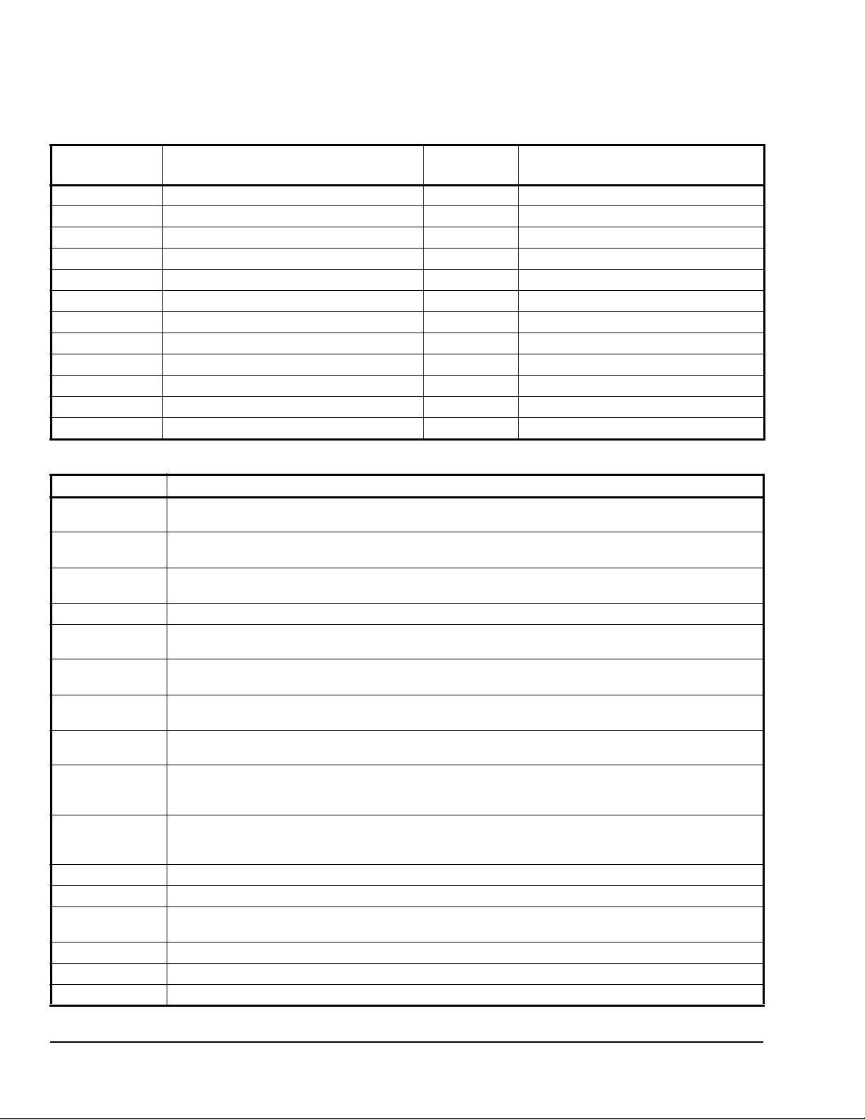
Ordering Information
Table 2: Electric Spring Return Actuator Models
Code Number Control Type Auxiliary
Switches
M9220-AGA-3 Floating None AC 24 V at 50/60 Hz or DC 24 V
M9220-AGC-3 Floating Two AC 24 V at 50/60 Hz or DC 24 V
M9220-BAA-3 On/Off None AC 120 V at 60 Hz
M9220-BAC-3 On/Off Two AC 120 V at 60 Hz
M9220-BDA-3 On/Off None AC 230 V at 50/60 Hz
M9220-BDC-3 On/Off Two AC 230 V at 50/60 Hz
M9220-BGA-3 On/Off None AC 24 V at 50/60 Hz or DC 24 V
M9220-BGC-3 On/Off Two AC 24 V at 50/60 Hz or DC 24 V
M9220-GGA-3 Proportional None AC 24 V at 50/60 Hz or DC 24 V
M9220-GGC-3 Proportional Two AC 24 V at 50/60 Hz or DC 24 V
M9220-HGA-3 Proportional w/Adjustable Zero and Span None AC 24 V at 50/60 Hz or DC 24 V
M9220-HGC-3 Proportional w/Adjustable Zero and Span Two AC 24 V at 50/60 Hz or DC 24 V
Table 3: Accessories and Replacement Parts (Order Separately)
Code Number Description
1
DMPR-KC003
M9000-158 Tandem Mounting Kit used to Mount Two Models of M9220-xxx-3 Series Proportional Electric Spring
M9000-200 Commissioning Tool that Provides a Control Signal to Drive 24 V On/Off, Floating, Proportional,
M9000-153 Crank arm
M9000-170 Remote Mounting Kit, Horizontal. Kit includes Mounting Bracket, M9000-153 Crank Arm, Ball Joint, and
M9000-171 Remote Mounting Kit, Vertical. Kit includes Mounting Bracket, M9000-153 Crank Arm, Ball Joint, and
M9000-320 Weather Shield Enclosure - NEMA 3R Enclosure for Protecting a Single M9210/20 Actuator from Rain,
M9000-604 Replacement Anti-rotation Bracket Kit (with Screws) for
M9220-600 1 in. (25 mm) Jackshaft Coupler Kit (with Locking Clip) for Mounting M9220-xxx-3 Proportional Electric
M9220-601 Replacement Coupler Kit (with Locking Clip) for Mounting M9220-xxx-3 Proportional Electric Spring
M9220-602 Replacement Locking Clips for M9220-xxx-3 Proportional Electric Spring Return Actuators (Five per Bag)
M9220-603 Adjustable Stop Kit for M9220-xxx-3 Proportional Electric Spring Return Actuators
M9220-604 Replacement Manual Override Cranks for M9220-xxx-3 Proportional Electric Spring Return Actuators
M9220-610 Replacement Shaft Gripper, 10 mm Square Shaft with Locking Clip
M9220-612 Replacement Shaft Gripper, 12 mm Square Shaft with Locking Clip
M9220-614 Replacement Shaft Gripper, 14 mm Square Shaft with Locking Clip
7 in. (178 mm) Blade Pin Extension (without Bracket) for Johnson Controls Direct-Mount Damper
Applications
Return Actuators
and/or Resistive Electric Actuators
Mounting Bolts
Mounting Bolts
Sleet, or Snow
M9220-xxx-3 Series Proportional Electric Spring Return Actuators
Spring Return Actuators on Dampers with 3/4 to 1-1/16 in. or 19 to 27 mm Round Shafts, or
5/8 and 3/4 in. or 16, 18, and 19 mm Square Shafts
Return Actuators on Dampers with 1/2 to 3/4 in. or 12 to 19 mm Round Shafts, or 3/8 and 1/2 in. or 10,
12, and 14 mm Square Shafts
(Five per Bag)
Power Requirements
1. Furnished with the damper and orderable separately.
M9220-xxx-3 Electric Spring Return Actuators Product Bulletin4
Page 5

Figure 2: M9220-xxx-3 Electric Spring Return Actuator Dimensions, in. (mm)
A
4
(102)
10-5/16
(262)
2-3/16
(56)
FIG:dmns
1-3/4
(44)
3-3/16
(81)
3/4
(19)
(56)
2
(51)
1-19/32
(40)
1-1/16
(27)
1/4 (6.5)
Mounti ng Hole
(6 Locations)
1-19/32
(40)
1-19/32
(40)
6-15/16
(176)
Dimensions
10
(254)
1/8
(3)
1
(25)
2-3/16
M9220-xxx-3 Electric Spring Return Actuators Product Bulletin 5
Page 6

Technical Specifications
M9220-xxx Series Electric Spring Return Actuators (Part 1 of 3)
Product Codes M9220-AGx-3 Models: Floating
M9220-Bxx-3 Models: On/Off
M9220-GGx-3 Models: Proportional
M9220-HGx-3 Models: Proportional Adjustable
Power Requirements AGx, HGx, GGx
Models
BAx Models AC 120 V (AC 102 to 132 V) at 60 Hz: 0.25 A Running, 0.13 A Holding
BDx Models AC 230 V (AC 198 to 264 V) at 50/60 Hz: 0.15 A Running, 0.09 A Holding
BGx Models AC 24 V (19.2 to 30 V) at 50/60 Hz: Class 2, 24.6 VA Running,
Transformer Sizing
Requirements
Input Signal/Adjustments AGx Models AC 19.2 to 30 V at 50/60 Hz or DC 24 V ±10%, Class 2;
Control Input Impedance GGx, HGx
Feedback Signal GGx Models 0 (2) to 10 VDC for Desired Rotation Range up to 90°;
Auxiliary Switch Rating xxC Models Two Single-Pole, Double-Throw (SPDT), Double-Insulated Switches with
Spring Return Direction is Selectable with Mounting Position of Actuator:
Running and Spring Return Torque 177 lb·in (20 N·m) for a Single Actuator;
AGx, HGx, GGx
Models
Bxx Models 25 VA Minimum per Actuator
GGx Models Factory Set DC 0 to 10 V, CW Rotation with Signal In crease;
HGx Models Factory Set DC 0 to 10 V, CW Rotation with Signal Increase;
Models
HGx Models 0 to 10 VDC for Desired Rotation Range up to 90°;
AC 24 V (19.2 to 30 V) at 50/60 Hz: Class 2, 15.5 VA Running,
7.7 VA Holding Position;
DC 24 V (21.6 to 26.4 V): Class 2, 6.7 W Running, 2.9 W Holding Position
Position
Position
7.7 VA Holding Position;
DC 24 V (21.6 to 26.4 V): Class 2, 17.6 W Running,
2.8 W Holding Position
20 VA Minimum per Actuator
Switch Selectable Direct or Reverse Action with Signal Increase
Selectable DC 0 (2) to 10 V or 0 (4) to 20 mA with Field Furnished 500
Ohm, 0.25 W Minimum Resistor; Switch Selectable Direct or Reverse
Action with Signal Increase
Selectable DC 0 to 10 V or 0 to 20 mA with Field Furnished 500 Ohm,
0.25 W Minimum Resistor;
Start Point Programmable DC 0 to 10 V;
Span Programmable DC2to10V;
Switch Selectable Direct or Reverse Action with Signal Increase
Voltage Input: 100,000 Ohms;
Current Input: 500 Ohms with Field Furnished 500 ohm Resistor
Corresponds to Rotation Limits, 1 mA maximum
Corresponds to Rotation Limits, 1 mA maximum
Gold Flash Contacts:
AC 24 V, 50 VA Pilot Duty;
AC 120 V, 5.8 A Resistive, 1/4 hp, 275 VA Pilot Duty;
AC 240 V, 5.0 A Resistive, 1/4 hp, 275 VA Pilot Duty
Side A, Actuator Face Away from Damper for CCW Spring Return;
Side B, Actuator Face Away from Damper for CW Spring Return
354 lb·in (40 N·m) for Two Models Mounted in Tandem
531 lb·in (60 N·m) for Three Models Mounted in Tandem
M9220-xxx-3 Electric Spring Return Actuators Product Bulletin6
Page 7

M9220-xxx Series Electric Spring Return Actuators (Part 2 of 3)
Valid Tandem Combinations Two M9220-Bxx-3
Three M9220-AGx-3
One M9220-HGx-3 Master with One or Two M9220-GGX-3 Slaves
One M9220-GGx-3 Master with One or Two M9220-GGX-3 Slaves
Rotation Range Adjustable from 30 to 90° CW or CCW with Optional
M9220-603 Adjustable Stop Kit; Mechanically Limited to 90°
Rotation Time
Power On (Running)
Rotation Time
Power Off
(Spring Returning)
Cycles 60,000 Full Stroke Cycles; 1,500,000 repositions
Audible Noise Rating
(AGx, HGx, GGx Models)
Audible Noise Rating
(BGx Models)
Electrical Connections Actuator
Conduit Connections Integral Connectors for 3/8 in. (10 mm) Flexible Metal Conduit
Mechanical Connections Standard
Aluminum Enclosure NEMA 2 (IP54) for All Mounting Orientations
Ambient Conditions Operating -40 to 131°F (-40 to 55°C); 90% RH Maximum, Noncondensing
Dimensions See Figure 2.
AGx Models 150 Seconds for 0 to 177 lb·in (0 to 20 N·m) at All Operating Conditions;
Independent of Load
HGx, GGx
Models
BGx Models 24 to 57 Seconds for 0 to 177 lb·in (0 to 20 N·m) at All Operating
AGx, HGx, GGx
Models
BGx Models 11 to 15 Seconds for 0 to 177 lb·in (0 to 20 N·m) at Room Temperature;
Power On
(Running)
Power On
(Holding)
Power Off
(Spring
Returning)
Power On
(Running)
Power On
(Holding)
Power Off
(Spring
Returning)
(All Models)
Auxiliary
Switches
(xxC Models)
Shaft Clamp
Included with
Actuator
Optional
M9220-600
Jackshaft
Coupler Kit
Storage -85 to 185°F (-65 to 85°C); 95% RH Maximum, Noncondensing
150 Seconds for 0 to 177 lb·in (0 to 20 N·m) at All Operating Conditions;
Independent of Load
90 Seconds for 0 to 177 lb·in (0 to 20 N·m) in Calibration or Override Mode
Conditions; 35 Seconds Nominal at Full Rated Load
20 Seconds for 0 to 177 lb·in (0 to 20 N·m) at Room Temperature
35 Seconds Maximum for 0 to 177 lb·in (0 to 20 N·m) at -22°F (-30°C)
130 Seconds Maximum for 0 to 177 lb·in (0 to 20 N·m) at -40°F (-40°C)
<40 dBA at 39-13/32 in. (1 m)
<20 dBA at 39-13/32 in. (1 m)
<55 dBA at 39-13/32 in. (1 m)
<66 dBA at 39-13/32 in. (1 m)
<18 dBA at 39-13/32 in. (1 m)
<66 dBA at 39-13/32 in. (1 m)
48 in. (1.2 m) Halogen-Free Cable with 18 AWG (0.75 mm
48 in. (1.2 m) Halogen-Free Cable with 18 AWG (0.75 mm2) Wire Leads
1/2 to 3/4 in. or 12 to 19 mm Diameter Round Shafts, or
3/8 and 1/2 in. or 10, 12, and 14 mm Square Shafts
3/4 to 1-1/16 in. or 19 to 27 mm Diameter Round Shafts, or
5/8 and 3/4 in. or 16, 18, and 19 mm Square Shafts
2
) Wire Leads
M9220-xxx-3 Electric Spring Return Actuators Product Bulletin 7
Page 8

Metasys® and Johnson Controls® are registered trademarks of Johnson Controls, Inc.
All other marks herein are the marks of their respective owners. © 2012 Johnson Controls, Inc.
Building Efficiency
507 E. Michigan Street, Milwaukee, WI 53202
M9220-xxx Series Electric Spring Return Actuators (Part 3 of 3)
Compliance North America UL Listed, File E27734, CCN XAPX (United States) and XAPX7 (Canada)
Europe CE Mark, EMC Directive 89/336/EEC (M9220-xGA-3 Models)
CE Mark, Low Voltage Directive 73/23/EEC
(M9220-BDA-3 and M9220-xxC-3 Models)
Australia and
New Zealand
Shipping Weight xGx Models 6.4 lb (2.9 kg)
BAx and BDx
Models
The performance specifications are nominal and conform to acceptable industry standards. For application at conditions beyond these
specifications, consult the local Johnson Controls office. Johnson Controls, Inc. shall not be liable for damages resulting from misapplication or
misuse of its products.
C-Tick Mark, Australia/NZ Emissions Compliant
(Models: All M9220-xGx and M9220-xDx)
7.6 lb (3.5 kg)
M9220-xxx-3 Electric Spring Return Actuators Product Bulletin 8
Published in U.S.A. www.johnsoncontrols.com
 Loading...