

Page 1
M9208-xxx-x Series Electric
Spring-Return Actuator
Electric Damper Actuators
Code No. LIT-1900562
M9208-xxx-x Series Electric Spring-Return Actuators
Description
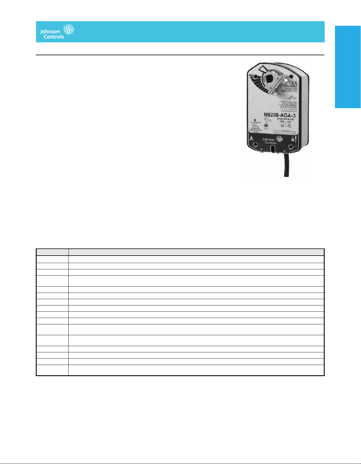
The M9208-xxx-x Series Electric
Spring-Return Actuators provide control of
dampers in HVAC systems. All actuators in
this series provide 70 lb·in (8 N·m) rated
torque. A mechanical spring-return system
provides rated torque with and without power
applied to the actuator. The series includes
the following control options:
• On/Off, 24 V, 120 VAC, 230 VAC power
• On/Off and Floating Point, 24 V power
• Proportional, 24 V power, for 0(2) to
10 VDC or 0(4) to 20 mA Control Signal
These actuators are configured for direct
mounting and do not require a damper
linkage. Actuators can be mounted directly to
a damper shaft from 5/16 to 5/8 in.
(8 to 16 mm) diameter with a universal clamp.
For shafts up to 3/4 in. (19 mm) diameter, use
the accessory Large Shaft Coupler Kit
M9208-600. An accessory crankarm and
remote mounting kit are available for
applications where the actuator cannot be
direct coupled to the damper shaft. Optional
line voltage auxiliary switches indicate an
end-stop position or perform switching
functions within the selected rotation range.
Refer to the M9208-xxx-x Series Electric
Spring-Return Actuators Product Bulletin
(LIT-12011480) for important product
application information.
Accessories and Replacement Parts
Code Number Description
1
DMPR-KC003
M9000-200 Commissioning Tool that Provides a Control Signal to Drive 24 V On/Off, Floating, Proportional, and/or Resistive Electric Actuators (Quantity 1)
M9000-321 Weather Shield Kit for Damper Application of M9203 and M9208 Series Elect ric Spring-Return Actuators (Quantity 1)
M9000-400 Jackshaft Linkage Kit. Open-Ended Design Enables Clamping onto a Jackshaft without Requiring Access to the Ends of the Jackshaft.
M9000-560 Ball Valve Linkage Kit for applying M9203 and M9208 Series Electric Spring-Return Actuators to VG1000 Series Valves (Quantity 1)
M9000-604 Replacement Anti-Rotation Bracket Kit for M9208, M9210, and M9220 Series Electric Spring-Return Actuators (Quantity 1)
M9000-606 Position Indicator for Damper Applications of M9203 and M9208 Series Actuators (Quantity 5)
M9200-100 Threaded Conduit Adapter, 1/2 NPSM, for M9210(20) and M(VA)9208 Series Actuators (Quantity 5)
M9208-100 Remote Mounting Kit, Including Mounting Bracket, M9208-150 Crankarm, Ball Joint, and Mounting Fasteners (Quantity 1)
M9208-150 Crankarm Adapter Kit (Quantity 1)
M9208-600 Large Shaft Coupler Kit (with Locking Clip) for Mounting M9208 Series Ele ctric Spring-Return Actuators on Dampers with Round Shafts from
M9208-601 Replacement Standard Coupler Kit (with Locking Clip) for Mounting M9208 Series Electric Spr i ng-Return Actuators on Dampers with Round
M9208-602 Replacement Locking Clips for M9208 Series Electric Spring-Return Actuators (Quantity 5)
M9208-603 Adjustable Stop Kit for M9208 Series Electric Spring-Return Actuators (Quantity 1)
M9208-604 Replacement Manual Override Cranks for M9208 Series Electric S pr ing-Retur n Actuators wi th Long Crank Rad ius: 2.83in .(72mm) (Quantit y 5)
M9208-605 Replacement Manual Override Cranks for M9208 Series Electric Spring-Return Actuators with Short Crank Radius: 1.83in.(46.5mm)
1. Furnished with the damper and may be ordered separately
7 in. (178 mm) Blade Pin Extension (without Bracket) for Johnson Controls Direct-Mount Damper Applicat ions (Quantity 1)
(Quantity 1)
1/2 to 3/4 in. (12 to 19 mm) or Square Shafts from 3/8to9/16in.(10 to 14 mm) (Quantity 1)
Shafts from 5/16 to 5/8 in. (8 to16mm) or Square Shafts from 1/4 to 1/2 in. (6 to 12 mm) (Quantity 1)
(Quantity 5)
Features
• 70 lb·in (8 N·m) rated torque
• direct-coupled design
• reversible mounting
• electronic stall detection
• double-insulated construction
• microprocessor-controlled
brushless DC motor
(-AGx and -GGx types)
• external mode selection switch
(-AGx and -GGx types)
• locking manual override with auto release
and crank storage
• integral cables with colored and numbered
conductors
• integral connectors for 3/8 in. (10 mm)
Flexible Metal Conduit (FMC)
• optional integrated auxiliary switches
• UL, CE, and C-Tick compliance
• manufactured under International
Standards Organization (ISO) 9001 quality
control standards
• 5-year warranty
Electric Damper ActuatorsElectric Damper ActuatorsElectric Damper ActuatorsElectric Damper Actuators
The performance specifications are nomina l and con form to accep table ind ustry stand ards. For applicati ons at con ditions be yond these specification s, consult th
Johnson Controls, Inc. shall not be liable for damages resulting from misapplication or misuse of its products. © 2014 Johnson Controls, Inc.
V–43
Page 2
Electric Damper Actuators
M9208-xxx-x Series Electric Spring-Return Actuators (Continued)
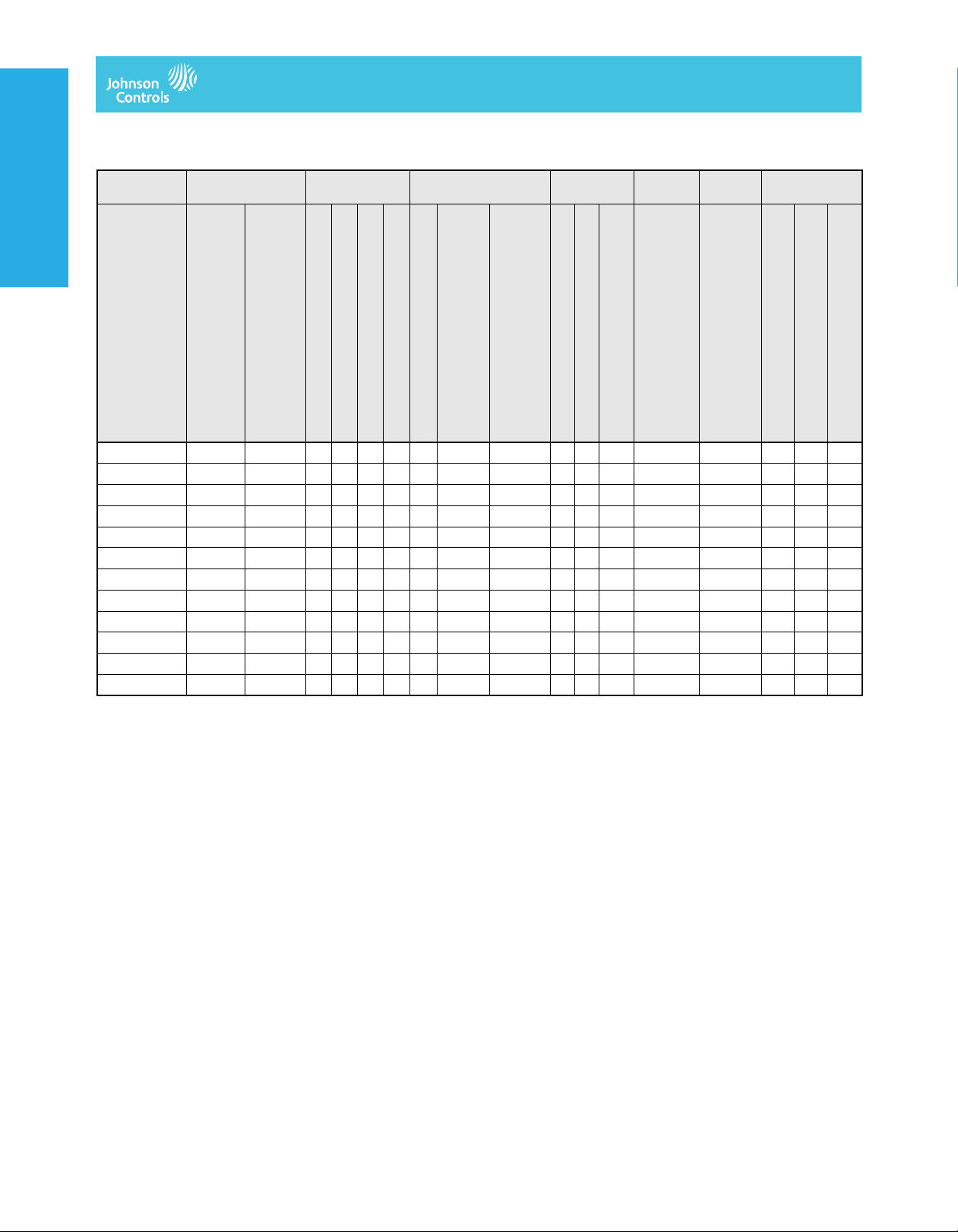
Selection Chart
Code Number Rotation Time
Electric Damper Actuators
Electric Damper ActuatorsElectric Damper Actuators
M9208-AGA-2
M9208-AGA-3
M9208-AGC-3
M9208-BGA-3
M9208-BGC-3
M9208-BAA-3
M9208-BAC-3
M9208-BDA-3
M9208-BDC-3
M9208-GGA-2
M9208-GGA-3
M9208-GGC-3
1. 22 seconds nominal at room temperature and rated load, 94 seconds maximum at rated load and -40ºF (-40ºC)
2. 21 seconds nominal at room temperature and rated load, 39 seconds maximum at rated load and -4ºF (-20ºC),
108 seconds maximum at 53 lb·in (6 N·m) and -40ºF (-40ºC)
(Seconds) for 90°
Power On (Running)
150
150
150
55 to 71
55 to 71
55 to 71
55 to 71
55 to 71
55 to 71
150
150
150
17 to 25
17 to 25
17 to 25
13 to 26
13 to 26
13 to 26
13 to 26
13 to 26
13 to 26
17 to 25
17 to 25
17 to 25
Electric Damper Actuators
Power
Requirements
Power Off (Spring Return)
24 VAC +/- 25%, VDC +20%/-10%
1
1
1
2
2
2
2
2
2
1
1
1
24 VAC +/- 20%, VDC +20%/-10%
■ 8 7.9 (5.5) — ■■ ■ ■
■ 8 7.9 (5.5) — ■■ ■ ■
■ 8 7.9 (5.5) — ■■ ■ ■ ■
■ 7 6.1 (1.2) — ■■■
■ 7 6.1 (1.2) — ■■■■
■ 8 7.9 (5.5) — ■■ ■■
■ 8 7.9 (5.5) — ■■ ■ ■
■ 8 7.9 (5.5) — ■■ ■■ ■
Power Consumption Input Signal Position
Feedback
120 VAC +/- 10%
230 VAC +/- 10%
VA Rating, Transformer Sizing
VA: Running (Holding)
■ — — 0.05 (0.03) ■■■
■ — — 0.05 (0.03) ■■■■
■ — — 0.04 (0.03) ■■■
■ — — 0.04 (0.03) ■■■■
Amperage: Running (Holding)
On/Off
Floating Point
0(2) to 10 VDC
0(4) to 20 mA (with 500 Ohm Resistor)
Auxiliary
Switches
0(2) to 10 VDC
2 Single-Pole, Double-Throw (SPDT),
5.0 A (2.9 A Inductive) at 240 V
Electrical
Connection
48 in. (1.2 m) 18 AWG Appliance Cable
120 in. (3.05 m) 19 AWG Plenum Cable
Integral 3/8 in. (10 mm) FMC Connectors
The performance specifications are no minal and co nform t o acceptab le ind ustry standar ds. For appl ications at condition s beyond these specifica tions, consult th
Johnson Controls, Inc. shall not be liable for damages resulting from misapplication or misuse of its products. © 2014 Johnson Controls, Inc.
V–44
Page 3

Electric Damper Actuators
M9208-xxx-x Series Electric Spring-Return Actuators (Continued)
Technical Specifications
M9208-GGx-x Series Proportional Electric Spring-Return Actuator (Part 1 of 2)
Power Requirements -GGx Models AC 24 V (AC 19.2 V to 28.8 V) at 50/60 Hz: Class 2 (North America) or Safety Extra-Low Voltage
Input Signal /
Adjustments
Control Input Impedance -GGx Models Voltage Input: 100,000 Ohms
Feedback Signal -GGx Models DC 0 (2) to 10 V for Desired Rotation Range up to 95°
Auxiliary Switch
Rating
Spring Return Direction is Selectable with Mounting Position of Actuator:
Rated Torque Power On (Running) 70 lb·in (8 N·m) All Operating Temperatures
Rotation Range Maximum Full Stroke: 95°
Rotation Time
for 90 Degrees of
Travel
Life Cycles 60,000 Full Stroke Cycles with 70 lb·in (8 N·m) Load
Audible Noise Rating Power On (Running) < 35 dBA at 70 lb·in (8 N·m) Load, at a Distance of 39-13/32 in. (1 m)
-GGx Models Factory Set at DC 0 to 10 V, CW Rotation with Signal Increase;
-xxC Models Two Single-Pole, Double-Throw (SPDT), Double-Insulated Switches with Gold over Silver Contacts:
Power Off
(Spring Returning)
Power On (Running) 150 Seconds Constant for 0 to 70 lb·in (8 N·m) Load,
Power Off
(Spring Returning)
(SELV) (Europe),
7.9 VA Running, 5.5 VA Holding Position
DC 24 V (DC 21.6 V to 28.8 V): Class 2 (North America) or SELV (Europe),
3.5 W Running, 1.9 W Holding Position
Minimum Transformer Size: 8 VA per Actuator
Selectable DC 0 (2) to 10 V or 0 (4) to 20 mA with Field Furnished 500 Ohm, 0.25 W Minimum Resistor;
Switch Selectable Direct or Reverse Action with Signal Increase
Current Input: 500 Ohms with Field Furnished 500 Ohm Resistor
Corresponds to Rotation Limits, 0.5 mA at 10 V Maximum
AC 24 V , 50 VA Pilot Duty
AC 120 V, 5.8 A Resistive, 1/4 hp, 275 VA Pilo t Duty
AC 240 V, 5.0 A Resistive, 1/4 hp, 275 VA Pilo t Duty
Actuator Face Labeled A is away from Damper or Valve: CCW Spring Return
Actuator Face Labeled B is away from Damper or Valve: CW Spring Return
70 lb·in (8 N·m) All Operating Temperatures
Adjustable Stop: 35° to 95° Maximum Position
At All Operating Conditions
17 to 25 Seconds for 0 to 70 lb·in (8 N·m) Load, at Room Temperature
22 Seconds Nominal at Full Rated Load
94 Seconds Maximum with 70 lb·in (8 N·m) Load, at -40°F (-40°C)
1,500,000 Repositions with 70 lb·in (8 N·m) Load
Electric Damper ActuatorsElectric Damper ActuatorsElectric Damper ActuatorsElectric Damper Actuators
Power On (Holding) < 20 dBA at a Distance of 39-13/32 in. (1 m)
Power Off
(Spring Returning)
Electrical Connections Models: GGx-3 48 in. (1.2 m) UL 758 Type AWM Halogen-Free Cable with 18 AWG
Models: GGA-2 120 in. (3.05 m) UL 444 Type CMP Plenum Rated Cable with 19 AWG
Auxiliary Switches
(-xxC Models)
Conduit Connections Integral Connectors for 3/8 in. (10 mm) Flexible Metal Conduit
Mechanical Connections Round Shafts Range of Sizes: 5/16 to 5/8 in. (8 to 16 mm)
Square Shafts Range of Sizes: 1/4 to 1/2 in. (6 to 12 mm)
Enclosure Rating NEMA 2 (IP54) for All Mounting Directions
Ambient Conditions Standard Operating -40 to 140°F (-40 to 60°C); 90% RH Maximum, Noncondensing
Storage -40 to 185ºF (-40 to 85ºC); 95% RH Maximum, Noncondensing
Dimensions 6.33 x 3.90 x 2.26 in. (160.7 x 99 x 57.5 mm)
The performance specifications are no minal and co nform t o acceptab le ind ustry standar ds. For appl ications at condition s beyond these specifica tions, consult th
Johnson Controls, Inc. shall not be liable for damages resulting from misapplication or misuse of its products. © 2014 Johnson Controls, Inc.
< 52 dBA at 70 lb·in (8 N·m) Load, at a Distance of 39-13/32 in. (1 m)
(0.85 mm²) Conductors and0.25 in. (6 mm) Ferrule Ends
(0.75 mm²) Conductors and 0.25 in. (6 mm) Ferrule Ends
48 in. (1.2 m) UL 758 Type AWM Halogen-Free Cable with 18 AWG
(0.85 mm²) Conductors and 0.25 in. (6 mm) Ferrule Ends
V–45
Page 4

Electric Damper Actuators
M9208-xxx-x Series Electric Spring-Return Actuators (Continued)
Compliance United States UL Listed, CCN XAPX, File E27734; to UL 60730-1A: 2003-08, Ed. 3.1,
Electric Damper Actuators
Electric Damper ActuatorsElectric Damper Actuators
Shipping Weight Models: -GGA: 3.43 lb (1.6 kg)
Power Requirements -AGx Models AC 24 V (AC 19.2 V to 28.8 V) at 50/60 Hz: Class 2 (North America) or Safety Extra-Low Voltage
Input Signal -AGx Models AC 19.2 to 28.8 V at 50/60 Hz or DC 24 V +20%/-10%,
Control Input Impedance -AGx Models 3,000 Ohm Control Inputs
Auxiliary Switch Rating -xxC Models Two SPDT, Double-Insulated Switches with Gold over Silver Cont acts:
Spring Return Direction is Selectable with Mounting Position of Actuator:
Rated Torque Power On (Running) 70 lb·in (8 N·m) All Operating Temperatures
Rotation Range Maximum Full Stroke: 95°
Rotation Time
for 90 Degrees of Travel
Electric Damper Actuators
M9208-GGx-x Series Proportional Electric Spring-Return Actuator (Part 2 of 2)
Automatic Electrical Controls for Household and Similar Use; and
UL 60730-2-14: 2002-02, Ed. 1, Part 2, Particular Requirements for Electric Actuators. (Models: All)
Canada UL Listed, CCN XAPX7, File E27734; to UL 60730-1:02-CAN/CSA:
Europe CE Mark – Johnson Controls, Inc. declares that this product is in compliance with the essential
Australia and
New Zealand
M9208-AGx-x Series On/Off and Floating Point Control Electric Spring-Return Actuator (Part 1 of 2)
Power Off
(Spring Returning)
Power On (Running) 150 Seconds Constant for 0 to 70 lb·in (8·N m) Load,
July 2002, 3rd Ed., Automatic Electrical Controls for Household and Similar Use; and CSA C22.2
No. 24-93 Temperature Indicating and Regulating Equipment (Models: All).
requirements and other relevant provisions of the EMC Directive 2004/108/EC and Low Voltage
Directive 2006/95/EC.
C-Tick Mark, Australia/NZ Emissions Compliant (Models: All)
Models: -GGC: 3.8 lb (1.7 kg)
(SELV) (Europe), 7.9 VA Running, 5.5 VA Holding Position
DC 24 V (DC 21.6 V to 28.8 V): Class 2 (North America) or SELV (Europe),
3.5 W Running, 1.9 W Holding Position
Minimum Transformer Size: 8 VA per Actuator
Class 2 (North America) or SELV (Europe)
Minimum Pulse Width: 500 ms
AC 24 V, 50 VA Pilot Duty
AC 120 V, 5.8 A Resistive, 1/4 hp, 275 VA Pilot Duty
AC 240 V, 5.0 A Resistive, 1/4 hp, 275 VA Pilot Duty
Actuator Face Labeled A is away from Damper or Valve: CCW Spring Return
Actuator Face Labeled B is away from Damper or Valve: CW Spring Return
70 lb·in (8 N·m) All Operating Temperatures
Adjustable Stop: 35 to 95° Maximum Posit i on
At All Operating Conditions
Power Off
(Spring Returning)
Life Cycles 60,000 Full Stroke Cycles with 70 lb·in (8 N·m) Load
Audible Noise Rating Power On (Running) < 35 dBA at 70 lb·in (8 N·m) Load, at a Distance of 39-13/32 in. (1 m)
Power On (Holding) < 20 dBA at a Distance of 39-13/32 in. (1 m)
Power Off
(Spring Returning)
Electrical Connections Models: AGx-3 48 in. (1.2 m) UL 758 Type AWM Halogen-Free Cable with 18 AWG
Models: AGA-2 120 in. (3.05 m) UL 444 Type CMP Plenum Rated Cable with 19 AWG
Auxiliary Switches
(-xxC Models)
Conduit Connections Integral Connectors for 3/8 in. (10 mm) Flexi ble Metal Conduit
Mechanical Connections Round Shafts Range of Sizes: 5/16 to 5/8 in. (8 to 16 mm)
Square Shafts Range of Sizes: 1/4 to 1/2 in. (6 to 12 mm)
Enclosure Rating NEMA 2 (IP54) for All Mounting Directions
The performance specifications are no minal and co nform t o acceptab le ind ustry standar ds. For appl ications at condition s beyond these specifica tions, consult th
Johnson Controls, Inc. shall not be liable for damages resulting from misapplication or misuse of its products. © 2014 Johnson Controls, Inc.
17 to 25 Seconds for 0 to 70 lb·in (8 N·m) Load, at Room Temperature
22 Seconds Nominal at Full Rated Load
94 Seconds Maximum with 70 lb·in (8 N·m) Load, at -40°F (-40°C)
1,500,000 Repositions with 70 lb·in (8 N·m) Load
< 52 dBA at 70 lb·in (8 N·m) Load, at a Distance of 39-13/32 in. (1 m)
(0.85 mm²) Conductors and 0.25 in. (6 mm) Ferrule Ends
(0.75 mm²) Conductors and 0.25 in. (6 mm) Ferrule Ends
48 in. (1.2 m) UL 758 Type AWM Halogen-Free Cable with 18 AWG
(0.85 mm²) Conductors and 0.25 in. (6 mm) Ferrule Ends
V–46
Page 5

Electric Damper Actuators
M9208-xxx-x Series Electric Spring-Return Actuators (Continued)
M9208-AGx-x Series On/Off and Floating Point Control Electric Spring-Return Actuator (Part 2 of 2)
Ambient Conditions Standard Operating -40 to 140°F (-40 to 60°C); 90% RH Maximum, Noncondensing
Storage -40 to 185ºF (-40 to 85ºC); 95% RH Maximum, Noncondensing
Dimensions 6.33 x 3.90 x 2.26 in. (160.7 x 99 x 57.5 mm)
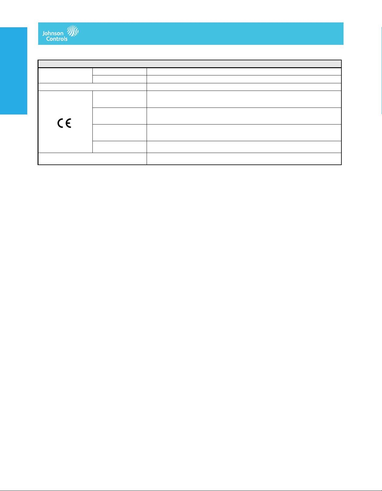
Compliance United States UL Listed, CCN XAPX, File E27734; to UL 60730-1A: 2003-08, Ed. 3.1,
Canada UL Listed, CCN XAPX7, File E27734; to UL 60730-1:02-CAN/CSA:
Europe CE Mark – Johnson Controls, Inc. declares that this product is in compliance with the essential
Australia and
New Zealand
Shipping Weight Models: -AGA: 3.43 lb (1.6 kg)
M9208-Bxx-3 Series On/Off Electric Spring-Return Actuators (Part 1 of 2)
Power Requirements -BGx Models AC 24 V (AC 18 V to 30 V) at 50/60 Hz: Class 2 (North America) or Safety Extra-Low Voltage (SELV)
-BAx Models AC 120 V (AC 102 V to 132 V) at 60 Hz: 0.05 A Running, 0.03 A Holding Position
Automatic Electrical Controls for Household and Similar Use ; and
UL 60730-2-14: 2002-02, Ed. 1, Part 2, Particular Requirements for Electric Actuators. (Models: All)
July 2002, 3rd Ed., Automatic Electrical Controls for Household and Similar Use; and CSA C22.2
No. 24-93 Temperature Indicating and Regulating Equipment (Models: All).
requirements and other relevant provisions of the EMC Directive 2004/108/EC and Low Voltage
Directive 2006/95/EC.
C-Tick Mark, Australia/NZ Emissions Compliant (Models: All)
Models: -AGC: 3.8 lb (1.7 kg)
(Europe), 6.1 VA Running, 1.2 VA Holding Position
DC 24 V (DC 21.6 V to 28.8 V): Class 2 (North America) or SELV (Europe), 3.5 W Running, 0.5 W
Holding Position
Minimum Transformer Size: 7 VA per Actuator
Electric Damper ActuatorsElectric Damper ActuatorsElectric Damper ActuatorsElectric Damper Actuators
-BDx Models AC 230 V (AC 198 V to 264 V) at 50/60 Hz: 0.04 A Running, 0.03 A Holding Position
Auxiliary Switch Rating -xxC Models T wo SPDT, Double-Insulated Switches with Gold over Silver Contacts:
Spring Return Direction is Selectable with Mounting Position of Actuator:
Rated Torque Power On (Running) 70 lb·in (8 N·m) All Operating Temperatures
Power Off
(Spring Returning)
Rotation Range Maximum Full Stroke: 95°
Rotation Time
for 90 Degrees of Travel
Life Cycles 60,000 Full-Stroke Cycles with 70lb·in(8N·m) Load
Audible Noise Rating Power On (Running) < 47 dBA at 70 lb·in (8 N·m) Load, at a Distance of 39-13/32 in. (1 m)
Power On (Running) 55 to 71 Seconds for 0 to 70 lb·in (8 N·m) Load, at All Operating Conditions
Power Off
(Spring Returning)
Power On (Holding) < 20 dBA at a Distance of 39-13/32 in. (1 m)
Power Off
(Spring Returning)
AC 24 V, 50 VA Pilot Duty
AC 120 V,5.8 A Resistive, 1/4 hp, 275 VA Pilot Duty
AC 240 V,5.0 A Resistive, 1/4 hp, 275 VA Pilot Duty
Actuator Side A is away from Damper or Valve: CCW Spring Return
Actuator Side B is away from Damper or Valve: CW Spring Return
70 lb·in (8 N·m) at Standard Oper ating Temperatures
53 lb·in (6 N·m) at Extended Operating Temperatures
Adjustable Stop: 35to 95°, Maximum Position
60 Seconds Nominal at Full Rated Load (0.25 rpm)
13 to 26 Seconds for 0 to 70 lb·in (8 N·m) Load, at Room Temperature
21 Seconds Nominal at Full Rated Load
39 Seconds Maximum with 70 lb·in (8 N·m) Load at -4°F (-20°C)
108 Seconds Maximum with 53 lb·in (6 N·m) Load at -40°F (-40°C)
< 52 dBA at 70 lb·in (8 N·m) Load, at a Distance of 39-13/32 in. (1 m)
Electrical Connections Actuator (All Models) 48 in. (1.2 m) UL 758 Type AWM Halogen-Free Cable with 18 AWG (0.85mm²) Conductors and
Auxiliary Switches
(-xxC Models)
Conduit Connections Integral Connectors for 3/8 in. (10 mm) Flexible Metal Conduit
Mechanical Connections Round Shafts Range of Sizes: 5/16 to 5/8 in. (8 to 16 mm)
Square Shafts Range of Size s: 1/4 to 1/2 in. (6 to 12 mm)
The performance specifications are no minal and co nform t o acceptab le ind ustry standar ds. For appl ications at condition s beyond these specifica tions, consult th
Johnson Controls, Inc. shall not be liable for damages resulting from misapplication or misuse of its products. © 2014 Johnson Controls, Inc.
0.25 in. (6 mm) Ferrule Ends
48 in. (1.2 m) UL 758 TypeAWM Halogen-Free Cable with 18 AWG (0.85 mm²) Conductors and
0.25 in. (6 mm) Ferrule Ends
V–47
Page 6
Electric Damper Actuators
M9208-xxx-x Series Electric Spring-Return Actuators (Continued)
Ambient Conditions Extended Operating -40 to -4°F (-40 to -20°C); 90% RH Maximum, Noncondensing
Dimensions 6.33 x 3.90 x 2.26 in. (160.7 x 99 x 57.5 mm)
Compliance United States UL Listed, CCN XAPX, File E27734; to UL 60730-1A: 2003-08, Ed. 3.1,
Electric Damper Actuators
Electric Damper ActuatorsElectric Damper Actuators
Shipping Weight Models: -BGC:3.75lb(1.7kg)
Electric Damper Actuators
M9208-Bxx-3 Series On/Off Electric Spring-Return Actuators (Part 2 of 2)
Storage -40 to 185°F (-40 to 85°C); 95% RH Maximum, Noncondensing
Automatic Electrical Controls for Household and Similar Use; and
UL 60730-2-14: 2002-02, Ed. 1, Part 2, Particular Requirements for Electric Actuators. (Models: All)
Canada UL Listed, CCN XAPX7, File E27734; to UL 60730-1:02- CAN/CSA:
Europe CE Mark – Johnson Controls, In c. declares that this product is in compliance with the essential
Australia and
New Zealand
July 2002, 3rd Ed., Automatic Electrical Controls for Household and Similar Use; and
CSA C22.2 No. 24-93 Temperature Indicating and Regulating Equipment (Models: All).
requirements and other relevant provisions of the EMC Directive 2004/108/EC and
Low Voltage Directive 2006/95/EC.
C-Tick Mark, Australia/NZ Emissions Compliant (Models: All)
Models: -BAC and -BDC: 4.15 lb (1.9 kg)
The performance specifications are no minal and co nform t o acceptab le ind ustry standar ds. For appl ications at condition s beyond these specifica tions, consult th
Johnson Controls, Inc. shall not be liable for damages resulting from misapplication or misuse of its products. © 2014 Johnson Controls, Inc.
V–48
 Loading...