

Page 1
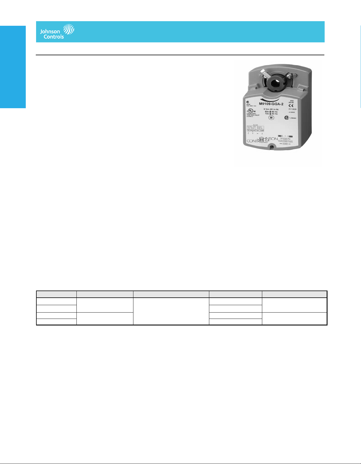
M9109-xGx-2 Series
Electric Non-Spring-Return Actuator
Electric Damper Actuators
M9109-xGx-2 Series Electric Non-Spring-Return Actuators
Description
The M9109 Series direct-mount electric
actuators operate on AC 24 V power and are
available for use with floating or proportional
controllers. These non-spring-return actuators
are easily installed on a VAV box, a round
Electric Damper Actuators
Electric Damper ActuatorsElectric Damper Actuators
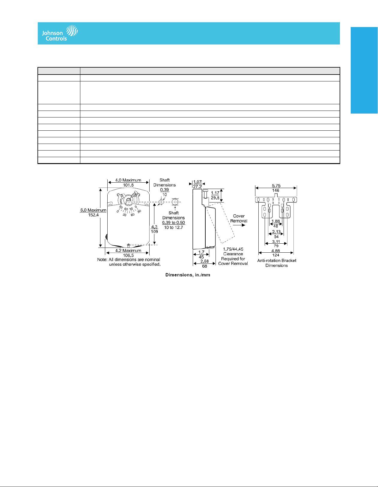
damper shaft up to 1/2 in. (13 mm) in diameter,
or a 3/8 in. (10 mm) square shaft. The M9109
with an M9000-520 linkage can be used to
control 2 in. (DN50) VG1000 Series ball
valves.
The M9109 models have 80 lb·in (9 N·m)
running torque. They have a nominal
60-second travel time for 90° of rotation at
60 Hz (72 seconds at 50 Hz) with a
load-independent rotation time. The
M9109-xGC-2 models are available with
integral auxiliary switches to perform switching
functions at any angle within the selected
rotation range.
Refer to the M9109 Series Electric
Non-Spring-Return Actuators Product Bulletin
(LIT-120112) for important product application
information.
Applications
The M9109 is used to position balancing,
control, round, and zone dampers in typical
HVAC applications. It can also be used with an
M9000-520 linkage to control VG1000 Series
ball valves. The M9109 mounts directly on the
duct surface, round damper, or small
rectangular damper with an anti-rotation
bracket and two sheet metal screws
(included). Additional linkages or couplers are
not required. For more information, refer to the
M9109 Series Electric Non-Spring-Return
Actuators Installation Instructions
(Part No. 34-636-1190).
Electric Damper Actuators
Features
• simple direct coupling reduces installation
and commissioning time and improves
reliability by eliminating damper linkages
Single screw coupling provides three-point
shaft gripping
• designed for zone damper and ball valve
actuator applications
• small, compact design allows installation in
tight-fitting locations
• designed for zone damper and ball valve
actuator applications
• floating and proportional control inputs
• 60-second running time at 60 Hz
• long life brushless synchronous drive motor
technology provides constant running time
independent of load
• robust 80 lb·in (9 N·m) torque rating
• whisper quiet 35 dBA noise rating
• magnetic clutch provides over torque
protection over the entire range of rotation
• -4 to 125°F (-20 to 52°C) ambient
temperature rating
• 100,000 full stroke cycle, 2,500,000
reposition rating
• manual gear release simplifies setup and
field adjustments
• 1/2 in. NPT threaded conduit opening
meets electrical code requirements and
allows the use of flexible armored cable
• position feedback (-GGX models) provides
simple, closed-loop control with accurate
position sensing
• adjustable rotation stops allow application
versatility with 30 to 90° clockwise or
counterclockwise rotation
Code No. LIT-1900154
Repair Information
If the M9109-xGx-2 Series Electric Actuator
fails to operate within its specifications,
replace the unit. For a replacement actuator,
contact the nearest Johnson Controls®
representative.
Selection Chart
Code Number Control Type Torque / Timing / Voltage Auxiliary Switches Comments
1
M9109-AGA-2
M9109-AGC-2
M9109-GGA-2 DC 0(2) to 10 V
M9109-GGC-2 2-SPDT
1. To avoid excessive wear or drive time on the motor for the -AGx models, use a controller and/ or sof tware t hat provid es a time- out fun cti on to remove th e si gnal at
the end of rotation (stall). The -GGx models have an auto shutoff to avoid excessive wear or drive time on the motor.
The performance specifications are nomina l and con form to accep table ind ustry stand ards. For applicati ons at con ditions be yond these specification s, consult th
Johnson Controls, Inc. shall not be liable for damages resulting from misapplication or misuse of its products. © 2014 Johnson Controls, Inc.
Floating 80 lb·in (9 N·m)
1
DC 0(4) to 20 mA proportional
60 seconds at 60 Hz
AC 24 V 50/60 Hz
None
2-SPDT
None DC 0(2) to 10 V feedback
V–30
Page 2
Electric Damper Actuators
M9109-xGx-2 Series Electric Non-Spring-Return Actuators (Continued)
Accessories
Code Number Description
DMPR-KC003 Square head blade pin extension without bracket
DMPR-KC010 Adjustable blade position indicator switch kit with total switching load limited to 2,000 VA for the following applications:
Pilot duty: AC 24 V, 50 VA; AC 125/250/277 V, 125 VA
Motor load: AC 125/250/277 V, 1/3 hp
Resistive load: AC 125 V, 11 A; AC 250 V, 8 A; AC 277 V, 7 A (all maximum values)
DMPR-KC011 Hex head blade pin extension without bracket
DMPR-KC012 Hex head blade pin extension with bracket
DMPR-KC213 Damper jackshaft 1/2 in. diameter , 1 panel
DMPR-KC214 Damper jackshaft 1/2 in. diameter , 2 panel
M9000-105 Pluggable 3-terminal block
M9000-106 Pluggable 4-terminal block
M9000-160 Replacement anti-rotation bracket for M9106 and M9109 Series actuators
M9000-200 Commissioning tool provides a control signal to drive on/off, floating, proportional, or resistive actuators
M9000-520 Valve linkage kit for field mountin g an M9109 act uator to a 2 in. (DN50) VG1000 Series ball valve
Electric Damper ActuatorsElectric Damper ActuatorsElectric Damper ActuatorsElectric Damper Actuators
The performance specifications are no minal and co nform t o acceptab le ind ustry standar ds. For appl ications at condition s beyond these specifica tions, consult th
Johnson Controls, Inc. shall not be liable for damages resulting from misapplication or misuse of its products. © 2014 Johnson Controls, Inc.
V–31
Page 3
Electric Damper Actuators
M9109-xGx-2 Series Electric Non-Spring-Return Actuators (Continued)
Technical Specifications
Power Requirement AGx: AC 20 to 30 V at 50/60 Hz, 2.5 VA supply, Class 2
Control Type AGx: floating
Electric Damper Actuators
Electric Damper ActuatorsElectric Damper Actuators
Input Signal AGx: AC 20 to 30 V at 50/60 Hz
Input Signal Adjustments: AGx: CW and COM terminals, CW rotation; CCW and COM terminals, CCW rotation
Input Impedance AGx: 200 ohms, nominal
Feedback Signal AGF: 10,000 ohm potentiometer, 1 W
Auxiliary Switch Rating xGC: two single-pole, double-throw (SPDT) switches rated at AC 24 V, 1.5 A inductive, 3.0 A resistive, 35 VA
Torque Rating 80 lb·in (9 N·m)
Cycle Life 100,000 full cycles; 2,500,000 repositions rated at 80 lb·in (9 N·m)
Audible Noise Rating 35 dBA maximum at 39.4 in. (1 m)
Rotation Range Adjustable from 30 to 90°, CW or CCW
Rotation Time 60 seconds at 60 Hz and 72 seconds at 50 Hz for 90°
Electrical Connection 1/4 in. spade terminals (to order optional pluggable terminal blocks, see Accessories
Mechanical Connection 3/8 to 1/2 in. (10 to 12.7 mm) round shaft or 3/8 in. (10 mm) square shaf t
Enclosure Rating NEMA 2, IP32
Ambient Operating Rating -4 to 125°F (-20 to 52°C); 90% RH maximum, noncondensing
Ambient Storage Rating -40 to 176°F (-40 to 80°C); 90% RH maximum, noncondensing
Shipping Weight 2.4 lb (1.08 kg)
Compliance United States UL 873 Listed, File E27734, CCN XAPX
Electric Damper Actuators
M9109-xGx-2 Series Electric Non-Spring-Return Actuators
GGx: AC 20 to 30 V at 50/60 Hz, 3.2 VA supply, Class 2
GGx: DC 0(2) to 10 V or DC 0(4) to 20 mA proportional
GGx: DC 0(2) to 10 V or DC 0(4) to 20 mA
GGx (voltage input or current input):
Jumper selectable: DC 0(2) to 10 V or DC 0(4) to 20 mA
Factory setting: DC 0 to 10 V, CW rotation with signal increase
Action is jumper selectable direct (CW) or reverse (CCW) with signal increase.
GGx: voltage input, 150,000 ohms; current input, 500 ohms
GGx: DC 0 to 10 V or DC 2 to 10 V for 90° (10 VDC at 1 mA);
Corresponds to input signal span selection
maximum per switch, Class 2
)
Canada CSA C22.2 No. 139 Certified, File LR85083, Class 3221 02
Europe CE Mark - Johnson Controls, Inc. declares that this product is in compliance with the essential requirements and
other relevant provisions of the EMC Directive 2004/108/EC.
The performance specifications are no minal and co nform t o acceptab le ind ustry standar ds. For appl ications at condition s beyond these specifica tions, consult th
Johnson Controls, Inc. shall not be liable for damages resulting from misapplication or misuse of its products. © 2014 Johnson Controls, Inc.
V–32
 Loading...