

Page 1
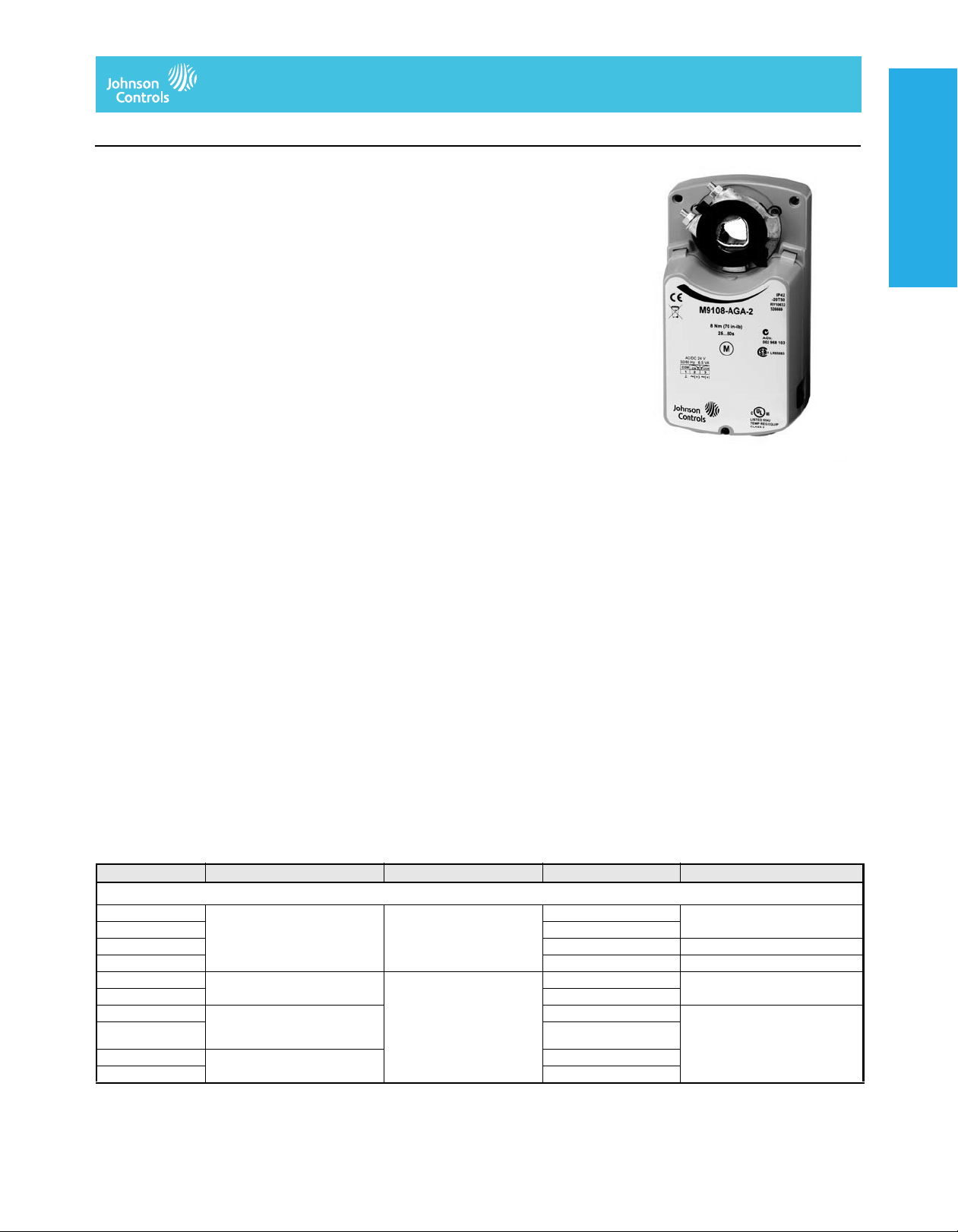
M9108 Series Electric
Non-Spring-Return Actuators
Electric Damper Actuators
Code No. LIT-1922030
M9108, M9116, M9124, and M9132 Series Electric Non-Spring-Return Actuators
Description
The M91xx Series includes M9108, M9116,
M9124, and M9132 models. All of these
direct-mount electric actuators operate on
AC/DC 24 V power. The M91xx actuators are
available for use with on/off, floating,
proportional, or resistive controllers. These
bidirectional actuators do not require a damper
linkage, and are easily installed on a damper
with a round shaft up to a 3/4 in. (20 mm) in
diameter or a square shaft up to 5/8 in.
(16 mm). They may be direct or remote
mounted to a damper, or mounted to a valve
using one of the M9000-5xx Valve Linkage
Kits.
A single M91xx model delivers up to 280 lb·in
(32 N·m) of torque. Two -AGx, -GGx, or -HGx
models in tandem deliver twice the torque or
560 lb·in (64 N·m). The angle of rotation is
mechanically adjustable from 0 to 90° in.
5-degree increments. Integral auxiliary
switches are available to indicate end-stop
position or to perform switching functions at
any angle within the selected rotation range.
Position feedback is available through
switches, a potentiometer, or a DC 0(2) to
10 V signal.
Features
• simple direct coupling reduces installation
and commissioning time while improving
reliability by eliminating damper linkages
• six torques: 70 to 560 lb·in (8 to 64 N·m)
offer the most suitable choice for the
application
• four control inputs meet the needs of most
applications
• output position feedback provides simple
closed-loop control with accurate position
sensing
• electronic stall detection ensures higher
reliability by deactivating the actuator motor
when a stall condition is detected
• master/slave operation allows
synchronized control for two actuators
• stacked for tandem applications
• zero and span adjustment (-HGx models)
allows sequential operation of dampers
from a single input signal of DC 0(2) to
10 V, DC 0(4) to 20 V, or DC 0(4) to 20 mA
• jumper-selectable rotation direction and
manual gear release simplify installation,
setup, and field adjustments
• NPT threaded housing provides easy
connection for electrical fittings
• manual gear release simplifies
damper/valve setup and commissioning
Applications
M91xx actuators are designed to position air
dampers and valves in HVAC systems.
Applications include: positioning return air or
exhaust dampers, controlling face and bypass
dampers, positioning blades for variable
volume fans, positioning VF4000 and
VF5000 Series butterfly valves, and
positioning VG1000 Series ball valves and
VG7000 Series globe valves when used with
the M9000-5xx Series Valve Linkages. Two of
the following models provide twice the amount
of running torque of a single unit when
mounted in tandem: M9116-GGx or -HGx,
M9124-AGx, -GGx or -HGx, and M9132-AGx
or -GGx.
Refer to the manufacturer’s information to
properly size the damper, valve, and/or
actuator. Spring-return actuators, such as the
M9206 and M9216 Series actuators, are
recommended for use with outdoor air
dampers in cold climates. These compact
M91xx actuators use a DC motor with stall
detection circuitry that operates throughout
the entire stroke.
The -GGx, -HGx, and -JGx models employ
noise-filtering techniques on the control signal
to eliminate repositioning due to line noise.
Rotation is mechanically limited to 93° by
integral end stops. The position of the actuator
is visually indicated from 0 to 90° on the cover.
An anti-rotation bracket prevents lateral
movement of the actuator. Pressing the
spring-loaded gear release on the actuator
cover disengages the gear train for manual
repositioning of the coupler.
Refer to the M9108, M9116, M9124, M9132
Series Electric Non-Spring-Return Actuators
Product Bulletin (LIT-2681058) or the M9108,
M9116, M9124, M9132 Series Electric
Non-Spring-Return Actuators Installation
Instructions (Part No. 34-636-399) for
important product application information.
Repair Information
If the M9108, M9116, M9124, or M9132 Series
Electric Actuator fails to operate within its
specifications, replace the unit. For a
replacement actuator, contact the nearest
Johnson Controls representative.
Electric Damper ActuatorsElectric Damper ActuatorsElectric Damper ActuatorsElectric Damper Actuators
Selection Chart
M9108, M9116, M9124, and M9132 Series Electric Non-Spring-Return Actuators (Part 1 of 2)
Code Number Control Type Torque / Timing / Voltage Auxiliary Switches Comments
M9108 Electric Non-Spring-Return Actuators
M9108-AGA-2 On/off, floating 70 lb·in (8 N·m)
M9108-AGC-2 2-SPDT
M9108-AGD-2 None 135 ohm potentiometer
M9108-AGE-2 None 1,000 ohm potentiometer
M9108-GGA-2 DC 0(2) to 10 V
M9108-GGC-2 2-SPDT
M9108-HGA-2 DC 0 to 10 V
M9108-HGC-2 2-SPDT
M9108-JGA-2 100 to 10,000 ohm potentiometer None
M9108-JGC-2 2-SPDT
The performance specifications are nomina l and con form to accep table ind ustry stand ards. For applicati ons at con ditions be yond these specification s, consult th
Johnson Controls, Inc. shall not be liable for damages resulting from misapplication or misuse of its products. © 2014 Johnson Controls, Inc.
DC 0(4) to mA proportional
DC 0 to 20 mA proportional
Adjustable start and span
25 to 50 seconds
AC 24 V 50/60 Hz
DC 24 V
70 lb·in (8 N·m)
25 to 50 seconds
AC 24 V 50/60 Hz
DC 24 V
V–33
None
None DC 0(2) to 10 V feedback
None DC 0 to 10 V feedback
Page 2
Electric Damper Actuators
M9108, M9116, M9124, and M9132 Series Electric Non-Spring-Return Actuators
(Continued)
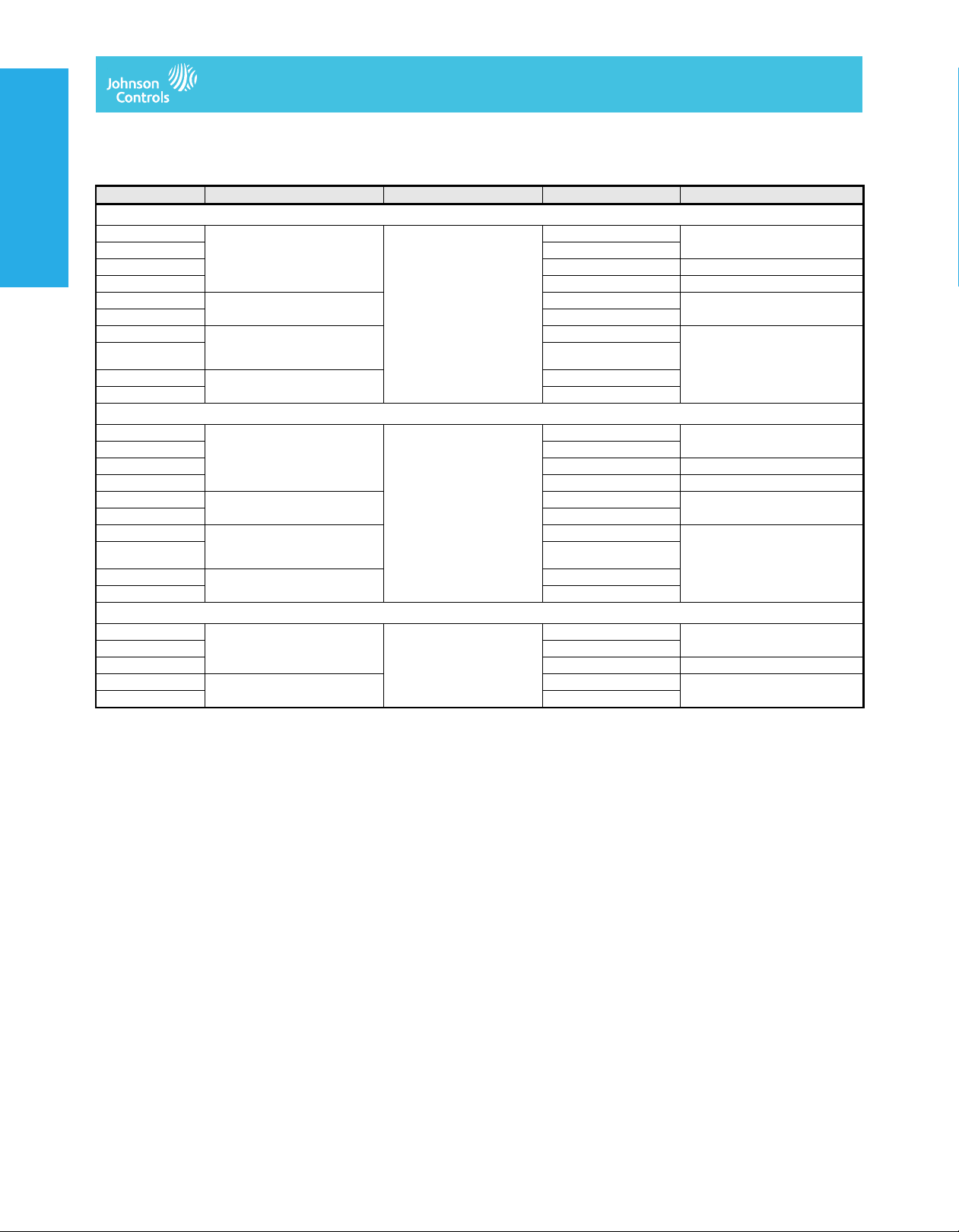
M9108, M9116, M9124, and M9132 Series Electric Non-Spring-Return Actuators (Part 2 of 2)
Code Number Control Type Torque / Timing / Voltage Auxiliary Switches Comments
M9116 Electric Non-Spring-Return Actuators
M9116-AGA-2 On/off, floating 140 lb·in (16 N·m)
M9116-AGC-2 2-SPDT
Electric Damper Actuators
Electric Damper ActuatorsElectric Damper Actuators
M9116-AGD-2 None 135 ohm potentiometer
M9116-AGE-2 None 1,000 ohm potentiometer
M9116-GGA-2 DC 0(2) to 10 V
M9116-GGC-2 2-SPDT
M9116-HGA-2 DC 0 to 10 V
M9116-HGC-2 2-SPDT
M9116-JGA-2 100 to 10,000 ohm potentiometer None
M9116-JGC-2 2-SPDT
M9124 Electric Non-Spring-Return Actuators
M9124-AGA-2 On/off, floating 210 lb·in (24 N·m)
M9124-AGC-2 2-SPDT
M9124-AGD-2 None 135 ohm potentiometer
M9124-AGE-2 None 1,000 ohm potentiometer
M9124-GGA-2 DC 0(2) to 10 V
M9124-GGC-2 2-SPDT
M9124-HGA-2 DC 0 to 10 V
M9124-HGC-2 2-SPDT
M9124-JGA-2 100 to 10,000 ohm potentiometer None
M9124-JGC-2 2-SPDT
M9132 Electric Non-Spring-Return Actuators
M9132-AGA-2 On/off, floating 280 lb·in (32 N·m)
M9132-AGC-2 2-SPDT
M9132-AGE-2 None 1,000 ohm potentiometer
M9132-GGA-2 DC 0(2) to 10 V
M9132-GGC-2 2-SPDT
DC 0(4) to mA proportional
DC 0 to 20 mA proportional
Adjustable start and span
DC 0(4) to mA proportional
DC 0 to 20 mA proportional
Adjustable start and span
DC 0(4) to mA proportional
Electric Damper Actuators
70 to 115 seconds
AC 24 V 50/60 Hz
DC 24 V
115 to 175 seconds
AC 24 V 50/60 Hz
DC 24 V
115 to 205 seconds
AC 24 V 50/60 Hz
DC 24 V
None
None DC 0(2) to 10 V feedback
None DC 0 to 10 V feedback
None
None DC 0(2) to 10 V feedback
None DC 0 to 10 V feedback
None
None DC 0(2) to 10 V feedback
The performance specifications are no minal and co nform t o acceptab le ind ustry standar ds. For appl ications at condition s beyond these specifica tions, consult th
Johnson Controls, Inc. shall not be liable for damages resulting from misapplication or misuse of its products. © 2014 Johnson Controls, Inc.
V–34
Page 3

Electric Damper Actuators
M9108, M9116, M9124, and M9132 Series Electric Non-Spring-Return Actuators
(Continued)
Accessories
Code Number Description
1
DMPR-KC003
DMPR-KC011 Hex head blade pin extension without bracket
DMPR-KC012 Hex head blade pin extension with bracket
DMPR-KC210 Damper jackshaft 1 in. diameter, 1 panel
DMPR-KC211 Damper jackshaft 1 in. diameter, 2 panel
DMPR-KC212 Damper jackshaft 1 in. diameter, 3 panel
DMPR-KC213 Damper jackshaft 1/2 in. diameter, 1 panel
DMPR-KC214 Damper jackshaft 1/2 in. diameter, 2 panel
M9000-103 14 VA transformer, 120/24 VAC, 60 Hz, Class 2
M9000-104 14 VA transformer, 230/24 VAC, 60 Hz, Class 2
M9000-105 Pluggable 3-terminal block
M9000-151 Base mount linkage kit for remote inside duct mounting (not intended for M9132 actuators or any tandem application)
M9000-153 Crankarm kit for remote mounting (not intended for M9132 actuators or any tandem application)
M9000-154 1 in. jackshaft coupler for mounting on a 1 in. diameter damper shaft
M9000-155 Manual handle for positioning a damper or valve when power is removed from an M91xx actuator
M9000-158 Mounting kit to tandem mount two M9116-GGx or -HGx models; two M9124-AGx, -GGx, or -HGx; or two M9132-AGx or -GGx models on a
M9000-160 Replacement anti-rotation bracket for M91xx Series actuators
M9000-200 Commissioning tool provides a control signal to drive on/off, floating, proportional, or resistive actuators
M9000-516 Valve linkage kit for mounting M9108 actuators to 1/2 in. to 2 in. two-way and three-way VG1000 Series ball valves
M9000-518 Valve linkage kit for mounting M9124 actuators to 2-1/2 in. to 4 in. VG1xA5 Series flange body ball valves to VG1x43 1-1/2 in. valves
1. Furnished with the damper and may be ordered separately
Square head blade pin extension without bracket for Johnson Controls® CD-1300 direct-mount applications
damper
Electric Damper ActuatorsElectric Damper ActuatorsElectric Damper ActuatorsElectric Damper Actuators
The performance specifications are no minal and co nform t o acceptab le ind ustry standar ds. For appl ications at condition s beyond these specifica tions, consult th
Johnson Controls, Inc. shall not be liable for damages resulting from misapplication or misuse of its products. © 2014 Johnson Controls, Inc.
V–35
Page 4

Electric Damper Actuators
M9108, M9116, M9124, and M9132 Series Electric Non-Spring-Return Actuators
(Continued)
Technical Specifications
Power Requirement M9108- and M9116 -AGx: AC 20 to 30 V at 50/60 Hz or DC 24 V ±10%; 6.5 VA supply mini mum
Control Type AGx: on/off and floating
Electric Damper Actuators
Electric Damper ActuatorsElectric Damper Actuators
Input Signal AGx: V 24 AC at 50/60 Hz or DC 24 V
Input Signal Adjustments AGx: factory setting, terminals 1 and 2, CW rotation; terminals 1 and 3, CCW rotation
Input Impedance GGx and HGx: voltage input, 205,000 ohms for 0 (2) to 10 V and 410, 000 ohms for 0 (4) to 20 V; current input,
Feedback Signal AGD: 135 ohm feedback potentiometer
Auxiliary Switch Rating xGC: two single-pole, double-throw (SPDT) switches rated at 24 VAC 1.5 A inductive, 3.0 A resistive, 35 VA
Torque Rating M9108: 70 lb·in (8 N·m) for one unit; not intended for tandem use
Cycle Life M9108, M9116 and M9124 60,000 cycles at rated load
Audible Noise Rating 45 dBA at 1 m
Rotation Range 0 to 90° in 5-degree increments, mechanically limited to 93° - rot ation range is ad justed by repositioning t he output
Rotation Time M9108: 30 seconds at 50% rated load, 25 to 50 seconds for 0 to 70 lb·in (0 to 8 N·m)
Electrical Connection M9124- and M9132-AGx: 1/4 in. spade terminals with pluggable 3-terminal blocks (see Accessories
Mechanical Connection 3/8 to 3/4 in. (10 to 20 mm) diameter round shaft or 3/8 to 5/8 in. (10 to 16 mm) square shaft
Enclosure Rating NEMA 2, IP42
Ambient Operating Rating -4 to 122°F (-20 to 50°C); 0 to 95% RH, noncondensing
Ambient Storage Rating -40 to 186°F (-40 to 86°C); 0 to 95% RH, noncondensing
Shipping Weight 2.9 lb (1.3 kg)
Compliance United States UL 873 Listed, File E27734, CCN XAPX
Electric Damper Actuators
M9108, M9116, M9124, and M9132 Series Electric Non-Spring-Return Actuators
All other models: AC 20 to 30 V at 50/60 Hz or DC 24 V ±10%; 7.5 VA supply minimum
GGx: DC 0(2) to 10 V or DC 0(4) to 20 mA proportional
HGx: DC 0 to 10 V or DC 0 to 20 mA proportional with adjustable start and span
JGx: proportional from 100 to 10,000 ohm potentiometer controller
GGx and HGx: DC 0(2) to 10 V, DC 0(4) to 20 V, or DC 0(4) to 20 mA
JGx: potentiometer value is 100 ohms minimum to 10,000 ohms maximum
GGx and HGx (voltage input or current input):
Jumper selectable: DC 0(2) to 10 V, DC 0(4) to 20 V, or DC0(4) to 20 mA
Adjustable: zero, DC 0 to 6 V, DC 0 to 12 V, or DC 0 to 12 mA
Span, DC 2 to 10 V, DC 4 to 20 V, or DC 4 to 20 mA
Factory setting: DC 0 to 10 V, DC 0 to 20 mA, CW rotation with signal increase
GGx, HGx, and JGx: action is jumper selectable direct (CW) or reverse (CCW) with signal increase.
500 ohms
JGx: 1.8 megohms
AGE: 1,000 ohm feedback potentiometer
GGx and HGx: DC 0 to 10 V or DC 2 to 10 V for 90° (10 VDC at 1 mA) corresponds to input signal span selection.
JGx: DC 0 to 10 V for 90° (10 VDC at 1 mA)
maximum per switch, Class 2
M9116: 140 lb·in (16 N·m) for one unit, 280 lb·in (32 N·m) for two in tandem (-GGx, -HGx)
M9124: 210 lb·in (24 N·m) for one unit, 420 lb·in (48 N·m) for two in tandem (-AGx, -GGx, -HGx)
M9132: 280 lb·in (32 N·m) for one unit, 560 lb·in (64 N·m) for two in tandem (-AGx , -GGx)
M9132 30,000 cycles at rated load
hub
M9116: 80 seconds at 50% rat ed load, 70 to 115 seconds for 0 to 140 lb·in (0 to 16 N·m)
M9124: 130 seconds at 50% rated load, 115 to 175 seconds for 0 to 210 lb·in (0 to 24 N·m)
M9132: 140 seconds at 50% rated load, 115 to 205 seconds for 0 to 280 lb·in (0 to 32 N·m)
)
All other models: screw terminals for 22 to 14 AWG; maximum of two 18, 20, or 22 AWG per terminal
1 in. (25.4 mm) diameter jackshaft with M9000-154 coupler
Canada CSA C22.2 No. 139 Certified, File LR85083, Class 3221 02
Europe CE Mark - Johnson Controls, Inc. declares that this product is in compliance with the essential requirements and
other relevant provisions of the EMC Directive 2004/108/EC.
The performance specifications are no minal and co nform t o acceptab le ind ustry standar ds. For appl ications at condition s beyond these specifica tions, consult th
Johnson Controls, Inc. shall not be liable for damages resulting from misapplication or misuse of its products. © 2014 Johnson Controls, Inc.
V–36
 Loading...