

Page 1
Damper
Damper
Shaft
Installation Instructions M9106AGx-2N0x
Issue Date June 3, 2014
M9106-AGx-2N0x Series Electric
Non-Spring Return Actuators
Installation
IMPORTANT: Use this M9106-AGx-2N0x Series
Actuator only to control equipment
under normal operating conditions.
Where failure or malfunction of the
actuators could lead to personal
injury or property damage to the
controlled equipment or other
property, additional precautions must
be designed into the control system.
Incorporate and maintain other
devices, such as supervisory or alarm
systems or safety or limit controls,
intended to warn of or protect against
failure or malfunction of the
actuators.
IMPORTANT : Utiliser ce M9106-AGx-2N0x Series
Actuator uniquement pour
commander des équipements dans
des conditions normales de
fonctionnement. Lorsqu'une
défaillance ou un dysfonctionnement
du actuators risque de provoquer des
blessures ou d'endommager
l'équipement contrôlé ou un autre
équipement, la conception du
système de contrôle doit intégrer des
dispositifs de protection
supplémentaires. Veiller dans ce cas
à intégrer de façon permanente
d'autres dispositifs, tels que des
systèmes de supervision ou d'alarme,
ou des dispositifs de sécurité ou de
limitation, ayant une fonction
d'avertissement ou de protection en
cas de défaillance ou de
dysfonctionnement du actuators.
The actuator may be mounted in any convenient
orientation. When installing the DPT-2015 Differential
Pressure Transmitter on the actuator, mount it so the
tubing connecting the flow pick-up device to the
DPT-2015 creates a moisture trap. This will prevent
condensation from entering the sensor.
Parts Included
• M9106-AGx-2N0x Actuator
• CBL-2000-1 Wiring Harness and DPT-2015-0
Differential Pressure Transmitter (included with the
M9106-AGS-2N02)
• No. 10 self-drilling sheet metal screw
Special Tools Needed
• 5/16 in. (8 mm) square socket
• 3/8 in. (10 mm) 12-point socket
• drill with a 5/16 in. hex nut driver
• digital voltmeter (for troubleshooting the
transmitter)
Mounting
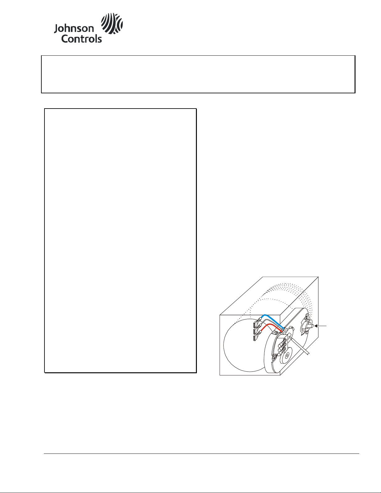
To mount the actuator to a damper:
1. Position the actuator on the damper shaft so the
damper shaft protrudes through the actuator
coupler as shown in Figure 1.
Figure 1: Mounting on the Damper Shaft
2. Make sure the actuator is in the desired mounting
position, parallel to the mounting surface as shown
in Figure 2.
No extra mounting brackets, linkage, or couplers are
required for standard mounting, but wiring terminals
must be accessible and protected from moisture and
corrosive fumes.
© 2014 Johnson Controls, Inc. 1
Part No. 34-636-1077, Rev. B www.johnsoncontrols.com
Page 2
Approximately
an 1/8 i n.
(3.2 mm) Gap
Gear
Release
Lever
Mounting
Surface
DPT-2015
Shoulder
Washer
Plastic Ribs
Self-drilling
Sheet Metal
Screw
CCW
COM
CW
O
U
T
G
N
D
I
N
(
-
)
L
O
D
PT
-2
015
Damper
Shaft
CCW to
Close
CW to
Close
Damper
Blade
Damper
Figure 2: Actuator Position
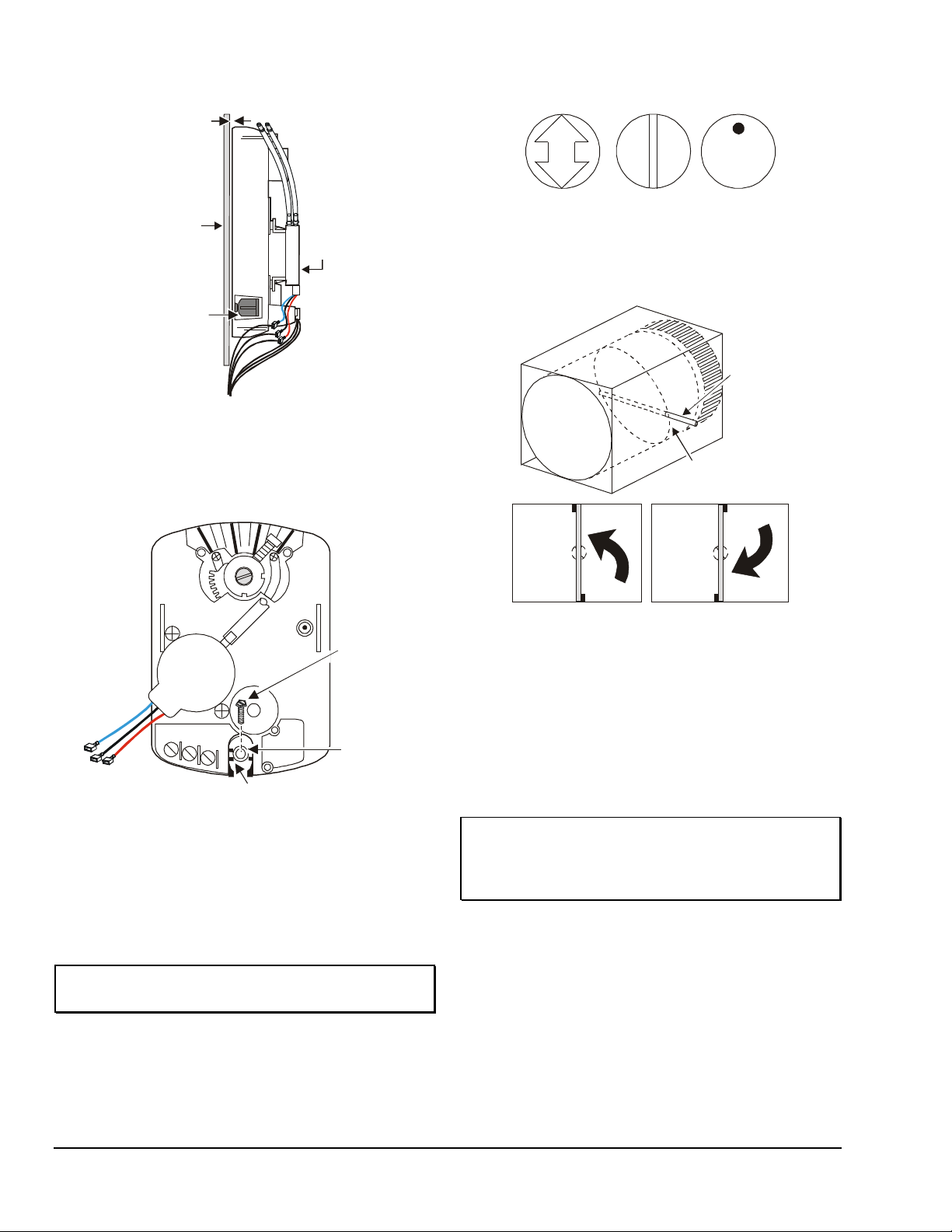
3. Verify that the shoulder washer is centered
between the plastic ribs of the actuator housing to
allow actuator movement during rotation.
(See Figure 3.)
Figure 4: Damper Position Icons
To set the actuator stroke, proceed as follows:
1. Grasp the damper shaft firmly with pliers and
rotate the damper fully closed. (See Figure 5.)
Figure 5: Damper Rotation
4. Hold the actuator in place on the damper shaft,
5. Place a 5/16 in. (8 mm) socket on the screw and
IMPORTANT: Do not overtighten the mounting
screw to avoid stripping the threads.
Rotation Range
Make sure that the damper blade is visually accessible
or its position is permanently marked on the end of the
damper shaft as shown in Figure 4.
2 M9106-AGx-2N0x Series Electric Non-spring Return Actuators Installation Instructions
Figure 3: Shoulder Washer Position
and insert the self-drilling sheet metal screw
through the shoulder washer. (See Figure 3.)
using a drill and extension, drill the screw into the
mounting surface until tight against the washer.
2. Press and hold the gear release lever shown in
Figure 2, and rotate the actuator coupler to the
fully closed position.
3. Make a note of the rotation travel and direction,
either Clockwise (CW) or Counterclockwise
(CCW), required to close the damper.
If rotation is less than 90°, proceed to Less Than
90 Degrees section.
IMPORTANT: Do not remove the sheet metal
screw and force the damper blade closed by rotating
the actuator. This puts additional stress on the gear
train and could reduce the life of the actuator.
90 Degrees
1. Release the gear release lever.
2. Secure the coupler to the shaft using a crescent
wrench or one of the tools from the Special Tools
Needed section to tighten the coupler set screw
against the damper shaft. (See Figure 6.)
Page 3

Coupler Set
Screw
45°
Damper
Shaft
End-stop
Set Screws on
End Sto ps
(2 each)
90°
30°
Stop Ge ar
60°
10°
COM
CW
CCW
Mounting
Bosses
Figure 6: Setting the Rotation Range
3. Keeping the actuator parallel to the mounting
surface, continue tightening the coupler set screw
approximately 1/2 turn to achieve 150 to 180 lb∙in
(17 to 20 N∙m) torque.
4. Press and hold the gear release lever, and turn the
coupler by hand to ensure the damper rotates from
end to end.
Proceed to the DPT-2015 section if needed.
Less Than 90 Degrees
If the damper shaft rotation is less than 90°, the stroke
of the actuator has to be adjusted using the scale on
the actuator. (See Figure 6.)
Use the center of the coupler set screw as a pointer to
observe the position on the scale when rotating the
coupler from one side to the other.
Examples:
• For a rotation range of 90°, set both end-stop
set screws fully up as shown in Figure 6.
IMPORTANT: Do not remove the end-stop
set screws, as this could interfere with the actuator’s
operation.
4. Hand tighten the set screw so it remains in this
position.
5. Secure the coupler to the shaft by using a crescent
wrench or one of the tools from the Special Tools
Needed section to tighten the coupler set screw
against the damper shaft. (See Figure 6.)
6. Keeping the actuator parallel to the mounting
surface, continue tightening the coupler set screw
approximately 1/2 turn to achieve 150 to 180 lb∙in
(17 to 20 N∙m) torque.
7. Repeat Steps 1 through 3 to set the desired
maximum rotation position.
8. Use the Phillips screwdriver to tighten both
end-stop set screws to a minimum of 25 lb∙in
(2.8 N∙m).
9. Press and hold the gear release lever, and turn the
coupler by hand to ensure the damper rotates from
end to end.
DPT-2015
The M9106-AGx-2N housing has two mounting bosses
for the DPT-2015. (See Figure 7.) Follow the
procedure in the installation instructions included with
the DPT-2015, DPT-2015 Differential Pressure
Transmitter for VAV Box Applications Installation
Instructions (Part No. 24-7547-18).
• For a rotation range of 60°, leave one end-stop
set screw fully up, and adjust the other one, so the
coupler rotates between the 30 and 90° indicator
marks on the scale.
• For a rotation range of 45°, adjust both end-stop
set screws, so the coupler rotates between 30 and
75°.
• For a rotation range of 30°, move both end-stop
set screws, so the coupler rotates between the
30 and 60° indicator marks on the scale.
To accurately set the end-stops:
1. Press and hold the gear release lever, and turn the
actuator coupler to the minimum rotation position
for the minimum ventilation flow required.
2. Release the gear release lever.
3. Use a Phillips screwdriver to loosen the end-stop
set screw that is closest to the stop gear. Move the
end-stop set screw in its slot until it is tight against
the stop gear. (See Figure 6.)
M9106-AGx-2N0x Series Electric Non-spring Return Actuators Installation Instructions 3
Figure 7: Location of the Mounting Bosses
Page 4

Wiring
!
!
CBL-20 00-x Wiring Harness
24
VAC
24
VAC
14.5 to 17
VDC
(+)
0.5 to 4.5
VDC
(+)
(-)
CCW COM CW IN GND OUT
Common
M9106-AGx-2N0x
DPT-2015
Upper Port
(-)LO
1/4 in. Ba rbe d P orts (2)
for Field-supplied Tubing
DPT-2015
CAUTION: Risk of Electric Shock.
Disconnect the power supply before making
electrical connections to avoid electric shock.
MISE EN GARDE : Risque de décharge
électrique. Débrancher l'alimentation avant de
réaliser tout raccordement électrique afin d'éviter tout
risque de décharge électrique.
The plenum-rated 20 in. (0.5 m) CBL-2000-2 and
72 in. (1.8 m) CBL-2000-3 Wiring Harnesses are also
available. (See Table 1.)
Setup and Adjustments
Air Pressure (M9106-AGS-2N02)
The flow pickup device provided with the Variable Air
Volume (VAV) box must be connected to the
DPT-2015 using field-supplied tubing as follows:
1. Cut two lengths of tubing, and connect them to the
flow pickup device.
CAUTION: Risk of Property Damage.
Do not apply power to the system before checking all
wiring connections. Short circuited or improperly
connected wires may result in permanent damage to
the equipment.
MISE EN GARDE : Risque de dégâts matériels.
Ne pas mettre le système sous tension avant d'avoir
vérifié tous les raccords de câblage. Des fils formant
un court-circuit ou connectés de façon incorrecte
risquent d'endommager irrémédiablement
l'équipement.
IMPORTANT: All wiring must be in accordance
with the National Electrical Code and local electrical
regulations.
The actuator requires a 24 VAC control signal and is
compatible with a variety of controllers. Refer to
Figure 8 for the wiring configuration.
IMPORTANT: Make sure the tubing is properly
sized and made of an elastic material, such as
silicone rubber, to ensure airtight connections and
minimize flow measurement errors.
2. Connect the tubing from the flow pickup device to
the corresponding barbed high and low pressure
ports on the DPT-2015. (See Figure 9.)
Note: The upper port is the low pressure port and
indicated as (-)LO on the transmitter.
Figure 8: Wiring Diagra m
Note: To avoid excessive wear or drive time on the
motor, use a controller and/or software that provides a
rotation (stall).
The 20 in. (0.5 m) CBL-2000-1 Wiring Harness,
accepted by Underwriters Laboratories, Inc.® (UL) for
time-out function to remove the signal at the end of
plenum use, is pre-wired with the M9106-AGS-2N02 or
may be ordered separately.
4 M9106-AGx-2N0x Series Electric Non-spring Return Actuators Installation Instructions
Figure 9: M9106-AGS-2N02 with Wiring Harness
3. Route the tubing so a portion of it is lower than the
DPT-2015. This creates a trap that prevents any
condensation from entering the sensor. Avoid
making any sharp bends in the tubing.
IMPORTANT: Overpressure limit is 15 in. W.C.
(3.74 kPa). Do not blow into ports to test their
operation, as this could damage the sensing
element.
Page 5

Commissioning
M9106-AGx-2N0x
After wiring is completed, apply power to the controller
and provide signals to the actuator to drive it at least
one complete cycle open and closed.
DPT-2015
To commission the transmitter:
1. Perform the checkout procedure provided in the
controller installation instructions, DPT-2015
Differential Pressure Transmitter for VAV Box
Applications Installation Instructions
(Part No. 24-7547-18), to ensure proper operation
of the transmitter.
Troubleshooting
M9106-AGx-2N0x
If the actuator is not responding or working properly:
• Verify that the actuator assembly is properly
secured to the duct.
• Check that all electrical connections are complete
and power is applied.
• Verify that the damper fully opens and closes,
using the gear release lever on the actuator.
• Check that the actuator stroke is set for the
desired application.
IMPORTANT: Perform commissioning when
the transmitter is permanently mounted and
operating at normal temperatures.
2. Set up and zero using HVAC PRO software
when using a DPT-2015 with a Johnson Controls
VAV Series controller. Refer to the Variable Air
Volume Controller Technical Bulletin
(LIT-6363040) for details.
• Verify that the air lines on the DPT-2015 are
connected to their respective high and low ports
with no kinks in the tubing.
• Check the supply voltage to ensure it is within the
14.5 to 17 VDC range and the polarity is correct.
• Disconnect the air lines from the high and low
ports, and place a voltmeter across the OUT and
GND terminals on the DPT-2015. If the output is
not between 0.4 and 0.6 volts with power applied
to the DPT-2015 in the vertical position, the
transmitter is defective and should be replaced.
Note: Voltage readings may vary by 0.1 volt if the
transmitter is in the horizontal position.
DPT-2015
The DPT-2015 must be auto zeroed by a
Johnson Controls VAV controller. If the DPT-2015 is
not operating properly:
M9106-AGx-2N0x Series Electric Non-spring Return Actuators Installation Instructions 5
Repairs and Replacement
Field repairs must not be made. For a replacement
product or an accessory, refer to the M9106-AGx-2N0x
Series Electric Non-Spring Return Actuators Product
Bulletin (LIT-2681126).
Page 6

Technical Data
Product
Input Signal
M9106-AGx-2N0x: 24 VAC (20 to 30 VAC) at 50 or 60 Hz
Mechanical Output
Audible Noise Rating
35 dBA maximum at 1 m
Rotation Range
Electrical Connection
Enclosure
NEMA1, IP30
Building Efficiency
M9106-AGx-2N0x Series Electric Non-Spring Return Actuators
Power Requirements M9106-AGA-2N01: 20 to 30 VAC at 50/60 Hz, 2.5 VA supply, Class 2
M9106-AGx-2N02: 20 to 30 VAC at 50/60 Hz, 2.1 VA supply, Class 2
DPT-2015: 15 VDC (14.5 to 17 VDC) unregulated; 15 mA maximum
Motor Input Impedance M9106-AGA-2N01: 200 ohms, nominal
M9106-AGx-2N02: 250 ohms, nominal
DPT-2015-0 Pressure Range: 0 to 1.5 in. W.C. (0 to 374 Pa)
Over Pressure Limit: 15 in. W.C. (3.74 kPa)
Output Voltage: 0.5 to 4.5 VDC with 25,000 ohm minimum load impedance
Running Torque: 53 lb∙in (6 N∙m)
Cycles 100,000 full cycles; 2,500,000 repositions rated at 53 lb∙in (6 N∙m)
Adjustable from 30 to 90°, CW or CCW
Rotation Time M9106-AGx-2N01: Nominal 60 seconds at 60 Hz and 72 seconds at 50 Hz for 90°
M9106-AGS-2N02: Nominal 120 seconds at 60 Hz and 144 seconds at 50 Hz for 90°
No. 6-32 screw terminals on the M9106 actuator; 1/4 in. spade terminals on the DPT-2015
Pressure Connection 6 in. (152 mm) length of silicone tubing with barbed fittings for 1/4 in. (6.35 mm)
O.D. tubing
Ambient Operating
Conditions
Ambient Storage
Conditions
Dimensions (H x W x D) M9106-AGA-2N01: 5.95 x 4.2 x 2.15 in. (151.2 x 107.3 x 54.6 mm)
Shipping Weight M9106-AGA-2N0x: 2.0 lb (0.91 kg)
Agency Compliance
(M9106 Actuator)
The performance specificati ons are nominal and conform to acceptable industry standards. For application at condit i ons beyond these
specifications, consult the local Johnson Control s office. Johnson Controls, I nc. shall not be liable for damages resulting from misapplication
or misuse of its products .
M9106-AGA-2N0x: 32 to 125°F (0 to 52°C); 90% RH maximum, non-condensing
M9106-AGS-2N02: 32 to 125°F (0 to 52°C); 90% RH maximum, non-condensing
60 to 100°F (16 to 38°C); 90% RH maximum, non-condensing
For DPT rated accuracy, see DPT-2015 Differential Pressure Transmitter for VAV Box
Applications Installation Instructions (Part No. 24-7547-18).
-20 to 150°F (-29 to 66°C); 90% RH maximum, non-condensing
M9106-AGx-2N02: 5.95 x 4.2 x 2.32 in. (151.2 x 107.3 x 58.9 mm) with the DPT-2015
M9106-AGS-2N02: 2.2 lb (0.99 kg) with the DPT-2015
UL 873 Listed, File E27734, CCN XAPX
CSA C22.2 No. 139 Certified, File LR85083, Class 3221 02
CE Mark, EMC Directive 89/336/EEC
507 E. Michigan Street, Milwaukee, WI 53202
Metasys® and Johnson Controls® are registered trademarks of Johnson Controls, Inc.
All other marks herein are the marks of their respective owners. © 2014 Johnson Controls, Inc.
6 M9106-AGx-2N0x Series Electric Non-spring Return Actuators Installation Instructions
 Loading...