

Page 1

M9102-AGA-1S and M9104-xGA-1S Series Electric
Non-Spring Return Actuators
Installation Instructions
Refer to the QuickLIT website for the most up-to-date version of this document.
Part No. 34-636-1506, Rev. F
Issued July 14, 2015
Applications
The M9102 and M9104 Series Actuators are directmount, non-spring return elec tric actuators that operate
on AC 24 V power. Employing a synchronous motor,
these actuators provide floating control (AGA), floating
control with automatic shut-off (IGA), and proportional
control with selectable 0-10 or 2-10 VDC (GGA).
All models are compact in size, and are easily installed
on Variable Air Volume (VAV) boxes, Variable Air
Volume and Temperature (VVT) two-position zone
applications, or small to medium-sized dampers with a
round shaft up to 13 mm in diameter, or a 10 mm
square shaft.
The M9102 Series Electric Non-Spring Return
Actuators provide a running torque of 2 N·m, and the
nominal travel time is 36 seconds at 50 Hz for 90° of
rotation.
The M9104 Series Electric Non-Spring Return
Actuators provide a running torque of 4 N·m, and the
nominal travel time is 72 seconds at 50 Hz for 90° of
rotation.
IMPORTANT: Use this M9102 or M9104 Series
Electric Non-Spring Return Actuator only to control
equipment under normal operating conditions.
Where failure or malfunction of the electric actuator
could lead to personal injury or property damage to
the controlled equipment or other property,
additional precautions must be designed into the
control system. Incorporate and maintain other
devices such as supervisory or alarm systems or
safety or limit controls intended to warn of, or protect
against, failure or malfunction of the electric
actuator.
IMPORTANT: Utiliser ce M9102 or M9104 Series
Electric Non-Spring Return Actuator uniquement
pour commander des équipements dans des
conditions normales de fonctionnement. Lorsqu'une
défaillance ou un dysfonctionnement du electric
actuator risque de provoquer des blessures ou
d'endommager l'équipement contrôlé ou un autre
équipement, la conception du système de contrôle
doit intégrer des dispositifs de protection
supplémentaires. Veiller dans ce cas à intégrer de
façon permanente d'autres dispositifs, tels que des
systèmes de supervision ou d'alarme, ou des
dispositifs de sécurité ou de limitation, ayant une
fonction d'avertissement ou de protection en cas de
défaillance ou de dysfonctionnement du electric
actuator.
M9102-AGA-1S and M9104-xGA-1S Series Electric Non-Spring Return Actuators
Installation Instructions
1
Page 2
Installation
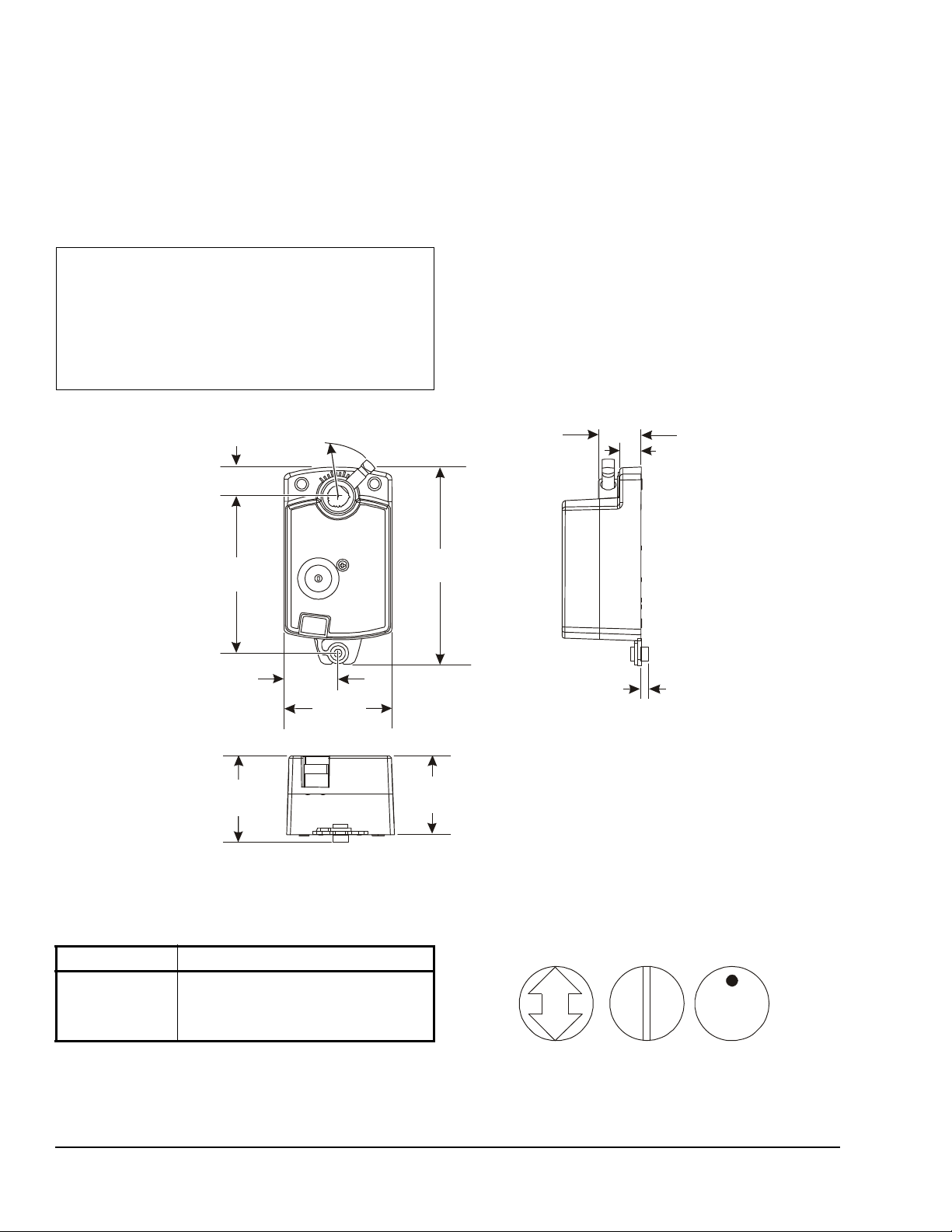
Figure 1: M9102 and M9104 Series Electric Non-Spring Return Actuator Dimensions, mm
36
71
104
131
57
32
20
Radius
Clearance
F
I
G
:
d
m
Figure 2: Damper Position Icons
The M9102 and M9104 Series Electric Non-Spring
Return Actuators mount directly to the surface in any
convenient orientation using a single No. 10 self-drilling
sheet metal screw (included with the actuator). No
additional linkages or couplers are required. Electrical
connections on the actuator are clearly labeled to
simplify installation.
IMPORTANT: Do not install or use this M9102 or
M9104 Series Electric Non-Spring Return Actuator
in or near environments where corrosive substances
or vapors could be present. Exposure of the electric
actuator to corrosive environments may damage the
internal components of the device, and will void the
warranty.
Set Screw
Parts Included
• one electric non-spring return actuator with an
integrated 1.2 m (48 in.) long cable
• one No.10 self-drilling sheet metal screw
Special Tools Needed
• 8 mm square socket
• #2 Phillips screwdriver
• 10 mm 12-point socket
• drill with a 8 mm hex nut driver
• digital voltmeter or M9000-200 Commissioning
Tool
28
14
Accessories
Table 1: Accessories (Order Separately)
Code Number Description
M9000-200 Commissioning Tool that Provides a
Mounting
To mount the actuator to a damper:
Control Signal to Drive 24 V On/Off,
Floating, Proportional, and/or Resistive
Electric Actuators
5
52
m
i
d
_
t
c
a
:
G
I
F
1. Check that the damper blade is visually accessible,
or its position is permanently marked on the end of
the damper shaft, as illustrated in Figure 2.
s
o
p
_
p
M9102-AGA-1S and M9104-xGA-1S Series Electric Non-Spring Return Actuators Installation Instructions2
Page 3
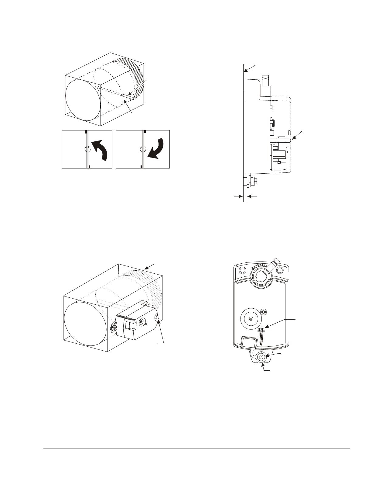
2. Grasp the damper shaft firmly with pliers and rotate
Shaft
CCW to
Close
CW to
Close
Blade
Damper
Figure 3: Damper Rotation
F
I
G
:
a
c
t
_
m
o
u
n
t
Damper
Shaft
Figure 4: Mounting the Actuator onto the
Damper Shaft
Figure 5: Positioning the Actuator
F
I
G
:
a
c
t
_
p
o
s
Button
Approximately a
5 mm Gap
Surface
Figure 6: Inserting the Screw into the Shoulder
Washer
No. 10
Sheet Metal
Screw
F
I
G
:
s
c
r
_
w
a
s
h
Plastic
Washer
Washer
the damper fully closed, as illustrated in Figure 3.
Damper
Damper
t
a
t
o
r
_
p
m
d
:
G
I
F
3. Press and hold the gear release lever, and rotate
the actuator coupler to the fully closed position.
4. Make a note of the rotation range and direction,
either Clockwise (CW) or Counterclockwise
(CCW), required to close the damper.
5. Position the actuator onto the damper shaf t so that
the damper shaft protrudes through the actu at or
coupler, as illustrated in Figure 4.
6. Be certain that the actuator is in the desired
mounting position parallel to the mounting surface,
as illustrated in Figure 5.
Mounting
Gear
Release
7. Hold the actuator in place on the damper shaf t, and
insert the No. 10 self-drilling sheet metal screw
through the shoulder washer as illustrated in
Figure 6.
Damper
Self-Drilling
Shoulder
Retainer
M9102-AGA-1S and M9104-xGA-1S Series Electric Non-Spring Return Actuators Installation Instructions 3
Page 4

8. Place a 8 mm socket on the screw and use a drill
Figure 7: M9102-AGA-1S and M9104-AGA-1S
Control Wiring Diagram
DA
1
3
F
I
G
:
M
9
1
0
x
-
A
G
A
-
1
S
d
i
DA
2
BLK
Figure 8: M9104-IGA-1S Control Wiring
Diagram - Floating
3
~
12
RED
BLK ORN
DA
DA
Figure 9: M9104-IGA-1S Control Wiring
Diagram - On/Off
312
BLK
DADA
and extension to drill the screw into the mounting
surface. Drive the screw until it is tight against the
washer.
IMPORTANT: Do not overtighten the mounting
screw. Overtightening may strip the threads.
9. Tighten the square cou pler bolt to the shaft using
an 8 mm (5/16 in.) wrench or 10 mm (3/8 in.) 12point socket. Tighten to 11 to 15 N·m (100 to 130
lb·in).
Wiring
M9102-AGA-1S, M9104-AGA-1S
The M9102 and M9104 Series Electric Non-Spring
Return Actuators require an AC 24 V input signal and
are compatible with a variety of VAV and VVT
controllers. These electric actuators include an
integrated 1.2 m (48 in.) long cable. See Figure 7 for
proper wiring.
g
a
RED ORN
M9104-IGA-1S
The M9104-IGA Series Electric Non-Spring Return
valve actuators require an AC 24 V input signal and
work with a variety of controllers. These electric
actuators include an integrated 1.2 m (48 in.) long
cable and have an auto-shutoff feature to preven t
excessive wear or drive time on the motor. See
Figure 8 and Figure 9 for proper wiring options.
AC 24 V 50/60 Hz
AC 24 V 50/60 Hz
~
Note: When using an AGA model, you must use a
VAV or VVT controller and/or software that provides a
timeout function at the end of rotation (stall) to avoid
excessive wear or drive time on the actuator motor.
ORN
RED
AC 24 V 50/60 Hz
~
Note: When using the VA9104-AGA-1S or
VA9104-IGA-1S Series actuator with a controller
featuring triac output, add a 4.7k ohm resistor one half
watt between the Common (COM) and CCW terminals.
M9102-AGA-1S and M9104-xGA-1S Series Electric Non-Spring Return Actuators Installation Instructions4
Page 5

M9104-GGA-1S
Figure 10: M9104-GGA-1S Control Wiring
Diagram
External Resistor
Y
DC 0(2)...10 V Control
DC 0(2)...10 V
~
2
AC 24 V
0(2)...10 V
1
DC 0(4)...20 mA
AC
24 V
Y
~
+
2
AC 24 V
1
!
!
Figure 11: Feedback Signal Relative to the
Rotation Range
10.0V
8.7V
7.3V
6.0V
4.7V
3.3V
10.0V
8.3V
6.7V
5.0V
3.3V
1.7V
75°
75°
60°
60°45°
45°
30°
30°
15°
15°
0°
0°
Rotation Range
2-10V
Feedback
0-10V
Feedback
Direct
Acting
2-10V
Feedback
Reverse
Acting
0-10V
Feedback
0.0V
1.7V
3.3V 5.0V
6.7V
8.3V
10.0V
10.0V
8.7V7.3V6.0V4.7V
3.3V2.0V
Figure 12: M9104-GGA Factory Switch Setting
The M9104-GGA Series Electric Non-Spring Return
valve actuators require AC 24 V power and a
DC 0(2) to 10 V or DC 0(4) to 20 mA controller input
signal. These electric actuators include an integrated
1.2 m (48 in.) long cable. See Figure 10 for proper
wiring.
BLK
RED
GRY ORN
4
3
90°
90°
0.0V
2.0V
k
b
d
f
:
G
I
F
AC
24 V
DC 0(2)...10 V
DC 0(4)...20 mA Control with
0(2)...10 V
BLK
RED
GRY
34
DC 0(2)...10 V
M9104-GGA actuators are factory set for Direct Acting
(DA) mode and for a DC 0 to 10 V input control signal.
In DA mode, a minimum control signal drives the
actuator to the full CCW position, and a maximum
control signal drives the actuator to the full CW
position.
For Reverse Acting (RA) operation, a minimum control
signal drives the actuator to the full CW position and a
maximum signal drives the actuator to the full CCW
position.
To change the factory settings (DA, 0-10 V), remove
the actuator cover and adjust the switches on the
circuit board as shown in Figure 12.
M9102-AGA-1S and M9104-xGA-1S Series Electric Non-Spring Return Actuators Installation Instructions 5
+
U
ORN
U
+
CAUTION: Risk of Electric Shock.
Disconnect the power supply before
making electrical connections to avoid
electric shock.
+
MISE EN GARDE : Risque de décharge
électrique.
Débrancher l'alimentation avant de
réaliser tout raccordement électrique afin
d'éviter tout risque de décharge
électrique.
CAUTION: Risk of Property Damage.
Do not apply power to the system before
checking all wiring connections. Short
circuited or improperly connected wires
may result in permanent damage to the
equipment.
MISE EN GARDE : Risque de dégâts
matériels.
Ne pas mettre le système sous tension
avant d'avoir vérifié tous les raccords de
câblage. Des fils formant un court-circuit
ou connectés de façon incorrecte
risquent d'endommager
irrémédiablement l'équipement.
Page 6

IMPORTANT: Make all wiring connections in
accordance with local, national, and regional
regulations. Do not exceed the electrical ratings of
the M9102 or M9104 Series Electric Non-Spring
Return Valve Actuator.
Setup and Adjustments
Commissioning
After wiring is completed, apply power to the VAV or
VVT controller and provide input signals to the actuator
to drive it at least one complete cycle open and closed.
Troubleshooting
If the M9102 or M9104 Series Electric Non-Spring
Return Actuator is not responding or working properly:
• verify that the actuator assembly is properly
secured to the duct
• check that all electrical connections are complete
and that power is applied
• verify that the damper fully opens and closes, using
the gear release button on the actuator
• check that the actuator stroke is set for the desired
application
Repairs and Replacement
If the M9102 or M9104 Series Electric Non-Spring
Return Actuator fails to operate within its specifications,
replace the unit. For a replacement electric actuator,
contact the nearest Johnson Controls® representative.
Technical Specifications
M9102-AGA-1S and M9104-xGA-1S Series Electric Non-Spring Return Actuators (Part 1 of 2)
Power Requirements M910x-AGA-1S AC 24 V +25%/-20% at 50/60 Hz, 2.1 VA, Class 2, Safety Extra-Low
M9104-IGA-1S AC 24 V +25%/-20% at 50/60 Hz, 3.0 VA, Class 2, SELV
M9104-GGA-1S AC 24 V +25%/-20% at 50/60 Hz, 2.9 VA, Class 2, SELV (Class III)
Control Ty pe M910x-AGA-1S Floating Control without Timeout
M9104-IGA-1S Floating or On/Off Control with Timeout
M9104-GGA-1S Proportional Control
Input Signal M9102-AGA-1S AC 24 V +25%/-20% at 50/60 Hz, Class 2, SELV
M9104-AGA-1S AC 24 V +25%/-20% at 50/60 Hz, Class 2, SELV
M9104-IGA-1S AC 24 V +25%/-20% at 50/60 Hz, Class 2, SELV
M9104-GGA-1S DC 0 (2) to 10 V or 0 (4) to 20 mA with field furnished 500 ohm resistor
Feedback Signal M9104-GGA-1S 0 to 10 VDC or 2 to 10 VDC for 90° (10 VDC at 1 mA)
Motor Input Impedance 200 ohms Nominal
Running Torque M9102 Series 2 N·m
M9104 Series 4 N·m
Travel Time M9102 Series 36 seconds at 50 Hz for 90° of rotation
M9104 Series 72 seconds at 50 Hz for 90° of rotation
Rotation Range 93° ±3°, CW or CCW
Cycles 100,000 Full Stroke Cycles;
Audible Noise Rating 35 dBA Nominal at 1 m
Electrical Connections M9104-AGA-1S
M9104-IGA-1S
M9104-GGA-1S
Mechanical Connections Up to 13 mm Diameter Round Damper Shaft or 10 mm Square Damper
Enclosure IP42, NEMA 2
Voltage (SELV)
Corresponds to input signal span selection
2,500,000 Repositions at Rated Running Torque
1.2 m (48 in.) Polyvinyl Chloride (PVC) cable with 0.75 mm
(19 AWG) and 6 mm (.25 in.) ferrule ends
2
1.2 m (48 in.) PVC cable with 0.75 mm
6 mm (.25 in.) ferrule ends
Shaft
conductors (19 AWG) and
2
conductors
M9102-AGA-1S and M9104-xGA-1S Series Electric Non-Spring Return Actuators Installation Instructions6
Page 7

Metasys® and Johnson Controls® are registered trademarks of Johnson Controls, Inc.
All other marks herein are the marks of their respective owners. © 2015 Johnson Controls, Inc.
Building Efficiency
507 E. Michigan Street, Milwaukee, WI 53202
M9102-AGA-1S and M9104-xGA-1S Series Electric Non-Spring Return Actuators (Part 2 of 2)
Ambient Conditions Operating -20 to 60°C; 90% RH Maximum, Noncondensing
Storage -29 to 66°C; 90 RH Maximum, Noncondensing
Compliance United States UL Listed, CCN XAPX, File 27734
Plenum rated, UL2043, suitable for use in other environmental spaces
(plenums) in accordance with section 300.22.(c) of the National Electrical
Code
Canada cUL Listed, CCN XAPX7, File 27734
Plenum Rated Per CSA 22.2 No. 236/UL 1995, Heating and Cooling
Equipment
Europe Johnson Controls, Inc. declares that this product is in compliance with the
essential requirements and other relevant provisions of the EMC Directive
2004/108/EC and the Low Voltage Directive 2006/95/EC.
Australia and
New Zealand
Shipping Weight 0.5 kg
The performance specifications are nominal and conform to acceptable industry standards. For application at conditions beyond these
specifications, consult the local Johnson Controls office. Johnson Controls, Inc. shall not be liable for damages resulting from misapplication or
misuse of its products.
C-Tick Mark, Australia/NZ Emissions Compliant
M9102-AGA-1S and M9104-xGA-1S Series Electric Non-Spring Return Actuators Installation Instructions 7
Published in U.S.A. www.johnsoncontrols.com
 Loading...