

Page 1

M9000-310 and M9000-320 Series Weather Shield
14- 1330-18, Rev. B
Enclosures
Installation Instructions
Applications
The M9000-310 and M9000-320 Weather Shield
Enclosures are cost-effective and durable weather
shields designed to provide a degree of protection for a
single Johnson Controls® M9000 Series Electric
Actuator used in either control damper or iron flanged
valve applications. These weather shield enclosures
are manufactured to National Electrical Manufacturers’
Association (NEMA) 3R specifications and protect the
electric actuator from corrosion, rain, freezing rain,
sleet, and snow. The enclosure can be mounted
indoors or outdoors; however, it may not prevent
externally formed ice from restricting the motion of the
rotary shaft.
Each enclosure is constructed of impact-grade ABS
plastic that provides excellent impact resistance. The
cover features ultraviolet inhibitors that extend service
life by preventing the cover from becoming brittle or
damaged by the sun or other environmental elements.
The transparent cover provides an unobstructed view
of the electric actuator without having to disassemble
the enclosure. An appliance cord enables installation of
control wiring, and a form-fitting seal prevents water or
moisture from entering the unit and damaging the
actuator.
IMPORTANT: The M9000-310 and M9000-320
Weather Shield Enclosures only provide protection
for the Johnson Controls M9000 Series Electric
Actuator used in control damper and iron flanged
valve applications. To ensure proper operation,
check that all associated equipment used in the
application is suitable for the surrounding
environment.
Part No. 14-1330-18, Rev. B
Issued
June 2016
Installation
Refer to the following documentation for more
information on the M9000 Series Electric Actuators and
Valve Linkages used with the M9000-310 and M9000320 Weather Shield Enclosures:
• M9106-xGx-2 Series Electric Non-Spring Return
Actuators Installation Instructions (Part No. 34636-1085)
• M9108, M91 1 6, M9124, and M9132 Series Electr
-Spring Return Actuators Installation
Non
Instructions (Part No. 34-636-399)
• M9109 Series Electric Non-spring Return
Actuators Installation Instructions (Part No. 34636-1190)
• M9220-AGx-3 Floating Electric Spring Return
Actuators Installation Instructions (Part No. 34636-1689)
• M9220-Bxx-3 On/Off Electric Spring Return
Actuators Installation Instructions (Part No. 34636-1239)
• M9220-GGx-3 Proportional Electric Spring Return
Actuators Installation Instructions (Part No. 34636-1697)
• M9000-53x Cast Iron Flanged V alve Linkage Kit for
Mounting a Single M9000 Series Electric Actuator
Installation Instructions (Part No. 14-1298-18)
• M9000-53x Series Cast Iron Flanged Va
kage Kit for Tandem Mounting of M9000 Series
Lin
Electric Actuators Installation Instruct
(
Part No. 14-1298-26)
lve
ions
ic
M9000-310 and M9000-320 Series Weather Shield Enclosures
Installation Instructions
1
Page 2
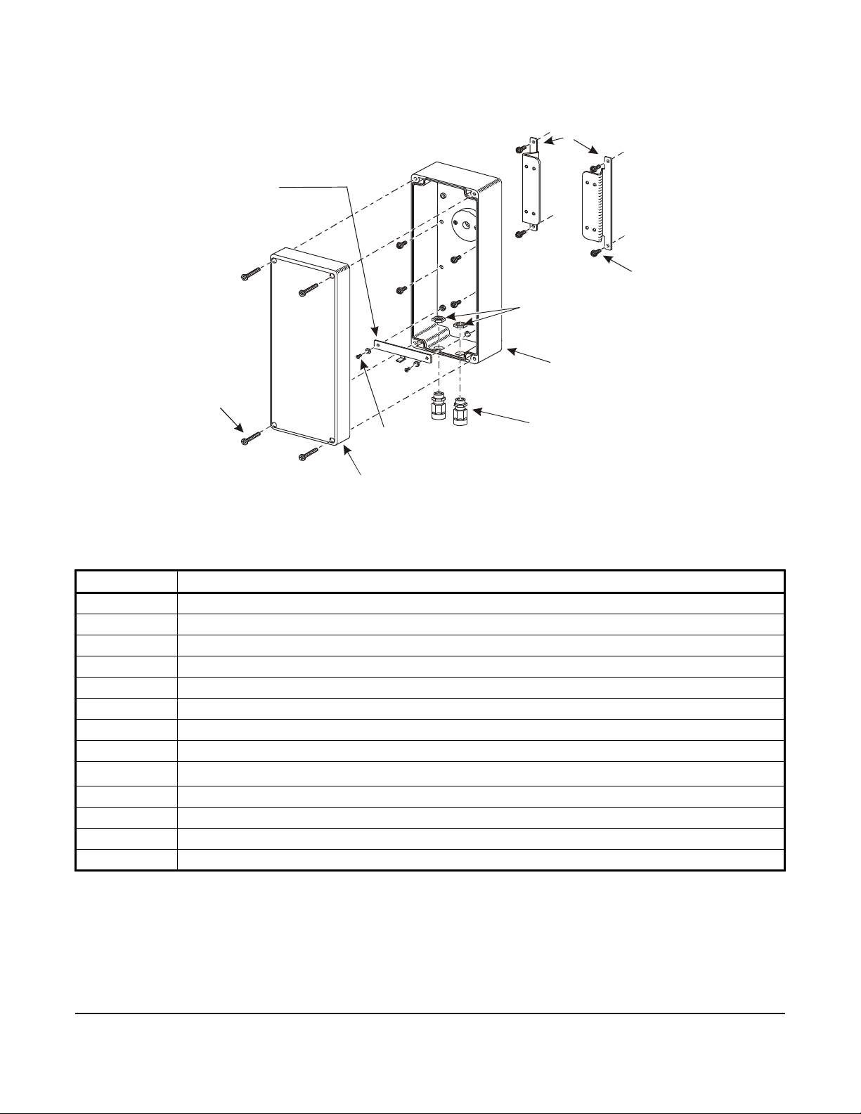
Parts Included
Hex-Head Screws
(Eight Lo cat ions)
Threaded
Hex Nuts
Enclos ure Base and
Seal Asse mbly
Cover Screws
(Four Locations)
Cover and
Strain Relief
Conduit Fittings
(Two Locat ions)
Anti-Rotation
Bracket
M3 x 8 mm
F
I
G
:
p
r
t
s
_
i
n
c
l
Figure 1: Parts Included in M9000-310 and M9000-320 Weather Shield Enclosure Kits (See Table 1)
Mounting
Brackets
No. 12-24 x 1/2 in.
Phillips Screws and
M4 Washers (Two Locations)
Gasket
Table 1: Parts Included in M9000-310 and M9000-320 Weather Shield Enclosure Kits
Quantity Description
1 Enclosure Base and Seal Assembly
1 Cover and Gasket
4 Cover Screws
2 Mounting Brackets
8 No. 12-24 x 1/2 in. Hex-Head Screws with Nitrile Patch
1 Anti-Rotation Bracket
2 M3 x 8 mm Phillips Screws
2 M4 Washers
2
1 Cap Plug
2 Threaded Hex Nuts
Strain Relief Conduit Fittings with 1/2 in. National Pipe Straight Mechanical (NPSM) Exit
1 Appliance Cord - 6 Conductor, 18 AWG Wire Gauge, 43 in. (109 cm)
1 Shaft Extender with Set Screw (M9000-320 Kit Only)
1. It is recommended that 1/2 in. liquid-tight conduit and 1/2 in. National Pipe Thread (NPT) liquid-tight fittings (purchased
locally) be used to terminate the control wiring to the weather shield enclosure strain relief conduit fittings.
1
M9000-310 and M9000-320 Series Weather Shield Enclosures Installation Instructions
2
Page 3
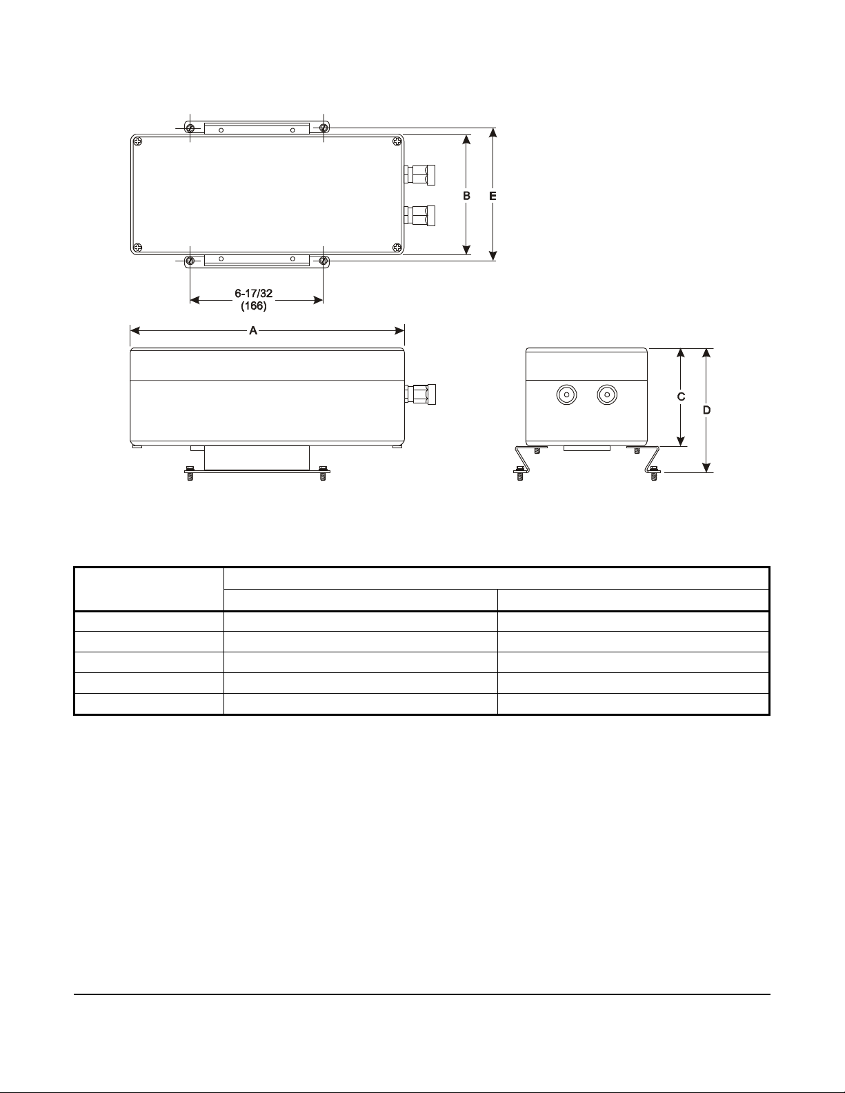
Dimensions
Figure 2: Weather Shield Enclosure Dimensions, in. (mm)
(See Table 2.)
s
n
m
d
:
G
I
F
Table 2: Weather Shield Enclosure Dimensions, in. (mm)
Dimension Weather Shield Enclosure
M9000-310 M9000-320
A 7-7/8 (200) 13-3/8 (340)
B 4-23/32 (120) 5-29/32 (150)
C 3-17/32 (90) 4-23/32 (120)
D 4-27/32 (123) 6-1/32 (153)
E 5-13/32 (137) 6-9/16 (167)
M9000-310 and M9000-320 Series Weather Shield Enclosures Installation Instructions
3
Page 4

Mounting
M9000-310
Bracket
Anti-Rotation
Bracket
Figure 3: Proper Orientation of the Anti- Rotation
Bracket
M9000-310
Figure 4: Proper Orientation of the
Mounting Brackets onto the Enclosure Base
The M9000-310 and M9000-320 Weather Shield
Enclosure Kits are shipped from the factory partially
assembled, with the cover held in place using the four
cover screws included with the kit. The remainder of
the parts required for moun ting can be foun d inside the
enclosure.
Control Damper Applications
Mount the weather shield enclosure onto a control
damper as follows:
1. Loosen the four cover screws using a No.1 Phillips
screwdriver and remove the cover and gasket
assembly from the enclosure base.
2. Orient the anti-rotation bracket onto the enclosure
as illustrated in Figure 3.
Note: The anti-rotation bracket must be oriented
properly for the anti-rotation tab to align with the slo t on
the electric actuator.
4. Orient the two mounting brackets onto the
enclosure base as illustrated in Figure 4.
M9000-320
5. Secure the mounting brackets to the enclosure
base using four No. 12-24 x 1/2 in. hex-head
screws (included with the kit).
Note: Each hex-head screw should be inserted from
the inside of the enclosure so that the nitrile patch
seals the mounting hole in the base.
t
k
r
b
t
n
m
:
G
I
F
Anti-Rotation
M9000-320
3. Secure the anti-rotation bracket to the threaded
brass inserts of the enclosure base using two
M3 x 8 mm Phillips screws and M4 washers
included with the kit. Tighten the Phillips screws to
a torque of 15 to 20 lb·in (1.7 to 2.3 N·m).
IMPORTANT: Do not overtighten the Phillips
screws. Overtightening may cause the threaded
inserts located in the enclosure base to become
dislodged, resulting in damage to the enclosure.
6. Install the enclosure and mounting bracket
assembly onto the damper shaft extension. Orient
the assembly so that the flanges of the mounting
brackets are flush with the mounting surface.
7. Using the mounting brackets as a template, mark
the mounting hole locations with a ball-peen
t
k
r
b
t
r
:
G
I
F
hammer and punch.
8. Remove the enclosure and mounting bracket
assembly from the damper shaft extension.
9. Drill pilot holes at each of the marked spots using a
drill and a No. 10 drill bit.
10. Reinstall the enclosure and mounting bracket
assembly onto the damper shaft extension. Orient
the assembly so that the flanges of the mounting
brackets are flush with the mounting surface and
the holes in the mounting brackets align with the
pilot holes drilled in Step 9.
11. Secure the enclosure and mounting bracket
assembly to the mounting surface using four
No. 12-24 x 1/2 in. hex-head screws included with
the kit. Tighten the hex-head screws to a torque of
20 to 25 lb·in (2.3 to 2.8 N·m).
M9000-310 and M9000-320 Series Weather Shield Enclosures Installation Instructions
4
Page 5

12. Install the two conduit fittings included with the kit
M9000-53x Series
Valve Lin kage
Primary Side of
M9000-53x Series
Valve Link age
Figure 5: Proper Orientation of the
Mounting Brackets onto the M9000-
53x Series Valve Linkage
into the enclosure base and secure them in place
using the threaded hex nuts.
IMPORTANT: The conduit fittings must be installed
properly to ensure a tight seal. Water or moisture
may damage or affect the operation of the electric
actuator within the enclosure.
13. Insert the appliance cord into one of the conduit
fittings so that the cable wrapping is visible inside
the enclosure. Tighten the conduit fitting to a
torque of 10 to 15 lb·in (1.1 to 1.7 N·m) to secure
the appliance cord in place.
14. Install the electric actuator onto the damper shaft
extension and the enclosure anti-rotation bracket.
Note: Refer to the documentation included with the
electric actuator for complete installation instructions.
15. Reinstall the cover and gasket assembly and
secure it in place using the four cover screws
included with the kit. Tighten the cover screws to a
torque of 5 to 8 lb·in (0.6 to 0.9 N·m) maximum.
IMPORTANT: The cover and gasket assembly
must be installed properly to ensure a tight seal.
Water or moisture may damage or affect the
operation of the electric actuator within the
enclosure.
3. Secure the anti-rotation bracket to the threaded
brass inserts of the enclosure base using two
M3 x 8 mm Phillips screws and M4 washers
included with the kit. Tighten the Phillips screws to
a torque of 15 to 20 lb·in (1.7 to 2.3 N·m).
IMPORTANT: Do not overtighten the Phillips
screws. Overtightening may cause the threaded
inserts located in the enclosure base to become
dislodged, resulting in damage to the enclosure.
4. Orient the two mounting brackets onto the primary
side of the M9000-53x Series Valve Linkage (for
single-mount applications) as illustrated in
Figure 5.
x
3
5
t
k
r
b
t
n
m
:
G
I
F
Secondary Side of
16. If one of the conduit fittings remains unused, seal
the fitting using the cap plug included with the
enclosure kit.
Iron Flanged Valve Applications
Mount the weather shield enclosure onto the M900053x Series Valve Linkage as follows:
1. Loosen the four cover screws using a No. 1 Phillips
screwdriver and remove the cover and gasket
assembly from the enclosure base.
2. Orient the anti-rotation bracket onto the enclosure
as illustrated in Figure 3.
Note: The anti-rotation bracket must be oriented
properly in order for the anti-rotation tab to align with
the slot on the electric actuator.
5. Secure the mounting brackets to the M900053x Series Valve Linkage using four No. 12-24 x 1/
2 in. hex-head screws (included with the kit).
6. Install the enclosure onto the input shaft of the
M9000-53x Series Valve Linkage. Orient the
enclosure so that the flanges of the mounting
brackets are flush with the surface of the enclosure
base.
7. Secure the enclosure to the mounting brackets
using four No. 12-24 x 1/2 in. hex-head screws
included with the kit. Tighten the hex-head screws
to a torque of 20 to 25 lb·in (2.3 to 2.8 N·m).
Note: Each hex-head screw should be inserted from
the inside of the enclosure so that the nitrile patch
seals the mounting hole in the base.
M9000-310 and M9000-320 Series Weather Shield Enclosures Installation Instructions
5
Page 6

8. Install the two conduit fittings included with the kit
Figure 6: Proper Mounting Position for Shaft
Extension
F
I
G
:
m
n
t
g
_
p
o
s
into the enclosure base and secure them in place
using the threaded hex nuts.
IMPORTANT: The conduit fittings must be installed
properly to ensure a tight seal. Water or moisture
may damage or affect the operation of the electric
actuator within the enclosure.
Steps 9 and 11 apply only to the M9000-320 kit when
used with the M9220 Series actuators. For the M90 00310 kit, proceed to Step 12.
9. For the M9000-320 kit used with the M9220 Series
actuators, install the shaft extension onto the input
shaft of the valve linkage. Ensure that the set
screws located on the shaft extension are oriented
perpendicular to the flat surfaces on the input shaft.
(See Figure 6.) To reduce friction, ensure that the
shaft extension and the seal assembly are not in
contact. A gap of no more than 1/8 in. is
recommended between these two components.
11. Using a flat blade screwdriver, remove and save
the spring clip from the M9220 actuator hub and
gripper assembly. Remove the actuator gripper
assembly from the actuator and retain.
12. Insert the appliance cord(s) for the actuator
through the conduit fittings.
13. Install the actuator into the enclosure/linkage
assembly. Insert the actuator anti-rotation slots
over the anti-rotation tab of th e bracket from
Step 3.
14. Center the shaft or shaft extension in the actuator
hub. For the M9220, reinstall the actuator gripper
assembly and secure in place using th e spring clip.
Secure the actuator coupler assembly to the shaft
following the actuator mounting instructions.
Note: Refer to the documentation included with the
electric actuator and valve linkage for complete
installation instructions.
15. Tighten the conduit fitting to a torque of 10 to
15 lb·in (1.1 to 1.7 N·m) to secure the appliance
cord in place.
16. Reinstall the cover and gasket assembly and
secure it in place using the four cover screws
included with the kit. Tighten the co ver scr ews to a
torque of 5 lb·in (0.6 N·m) maximum.
17. If the valve application is a tandem configuration,
repeat Steps 11 through 16 on the secondary side
of the M9000-53x Series Valve Linkage.
10. Secure the shaft extension to the input shaft of the
valve linkage using the supplied set screws and 5/
16 in. (8 mm) wrench. The recommended torque
applied to the set screws is 100 in·lb (11 N·m).
Tighten the screws evenly.
IMPORTANT: The cover and gasket assembly
must be installed properly to ensure a tight seal.
Water or moisture may damage or affect the
operation of the electric actuator within the
enclosure.
18. If one of the conduit fittings remains unused, seal
the fitting using the cap plug included with the
enclosure kit.
Repair Information
If the M9000-310 or M9000-320 Ser ies Weathe r Shield
Enclosure fails to operate within its specifications,
replace the unit. For a replacement weather shield,
contact the nearest Johnson Controls representative .
M9000-310 and M9000-320 Series Weather Shield Enclosures Installation Instructions
6
Page 7

Metasys® and Johnson Controls® are registered trademarks of Johnson Controls, Inc.
All other marks herein are the marks of their respective owners. © 2016 Johnson Controls, Inc.
Building Efficiency
507 E. Michigan Street, Milwaukee, WI 53202
Technical Specifications
M9000-310 and M9000-320 Weather Shield Enclosures
Materials Enclosure Impact-Grade ABS Plastic
Enclosure Seal Nitrile
Cover Transparent Impact-Grade ABS Plastic with Ultraviolet Inhibitors
Cover Gasket Neoprene
Weather Shield Rating NEMA 3R, IP32
Actuator Ambient
Operating
Temperature Limits
Weather Shield Enclosure Ambient Storage
Temperature Limits
Electrical Connections Strain Relief Conduit Fittings with 1/2 in. National Pipe Straight Mechanical
Shipping Weight M9000-310 2.0 lb (0.9 kg)
The performance specifications are nominal and conform to acceptable industry standards. For application at conditions beyond these
specifications, consult the local Johnson Controls office. Johnson Controls, Inc. shall not be liable for damages resulting from misapplication or
misuse of its products.
M9106 and M9109
(M9000-310 Only)
M9108, M9116,
M9124, and M9132
M9220 -40 to 131°F (-40 to 55°C)
M9000-320 3.3 lb (1.5 kg)
-4 to 122°F (-20 to 50°C)
-4 to 122°F (-20 to 50°C)
-40 to 176°F (-40 to 80°C)
(NPSM) Exit
European Single Point of Contact: NA/SA Single Point of Contact: AP AC Single Point of Contact:
JOHNSON CONTROLS
WESTENDHOF 3
45143 ESSEN
GERMANY
JOHNSON CONTROLS
507 E MICHIGAN ST
MIL WAUKEE WI 53202
USA
JOHNSON CONTROLS
C/O CONTROLS PRODUCT MANAGEMENT
NO. 22 BLOCK D NEW DISTRICT
WUXI JIANGSU PROVINCE 214142
CHINA
M9000-310 and M9000-320 Series Weather Shield Enclosures Installation Instructions
Published in U.S.A. www.johnsoncontrols.com
7
 Loading...