

Page 1
Code No. LIT-12012114
Installation Manual
Effective July 2015
JC-VSD Factory Packaged (FP) Series II
drive frames 4–8, Type 1 and 3R
Page 2

Page 3

Johnson Controls variable speed drives
Disclaimer of warranties and limitation of liability
The product discussed in this literature is subject to terms and conditions outlined in
Johnson Control Inc. selling policies. The sole source governing the rights and remedies
of any purchaser of this equipment is the relevant Johnson Control Inc. selling policy.
NO WARRANTIES, EXPRESS OR IMPLIED, INCLUDING WARRANTIES OF FITNESS FOR
A PARTICULAR PURPOSE OR MERCHANTABILITY, OR WARRANTIES ARISING FROM
COURSE OF DEALING OR USAGE OF TRADE, ARE MADE REGARDING THE
INFORMATION, RECOMMENDATIONS AND DESCRIPTIONS CONTAINED HEREIN
In no event will Johnson Control Inc. be responsible to the purchaser or user in contract, in
tort (including negligence), strict liability or otherwise for any special, indirect, incidental or
consequential damage or loss whatsoever, including but not limited to damage or loss of use
of equipment, plant or power system, cost of capital, loss of power, additional expenses in
the use of existing power facilities, or claims against the purchaser or user by its customers
resulting from the use of the information, recommendations and descriptions contained
herein. The information contained in this manual is subject to change without notice.
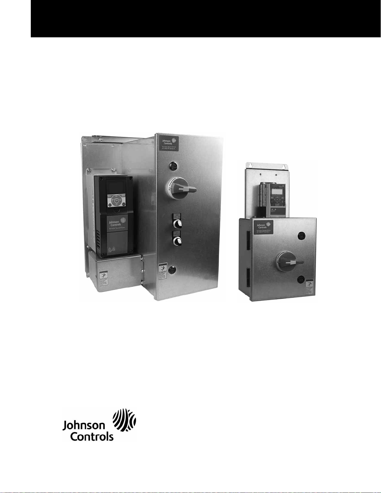
Cover Photo: Johnson Controls variable speed drives
Safety
Read and follow all safety information shown in the JC-VSD Series II Installation Manual
LIT-12011775.
Johnson Controls variable speed drives LIT-12012114—July 2015 www.johnsoncontrols.com i
Page 4

Johnson Controls variable speed drives
Table of contents
SAFETY
Definitions and symbols . . . . . . . . . . . . . . . . . . . . . . . . . . . . . . . . . . . . . . . . . . v
Hazardous high voltage . . . . . . . . . . . . . . . . . . . . . . . . . . . . . . . . . . . . . . . . . . . v
Warnings and cautions . . . . . . . . . . . . . . . . . . . . . . . . . . . . . . . . . . . . . . . . . . . v
GENERAL INFORMATION
Catalog/style numbering . . . . . . . . . . . . . . . . . . . . . . . . . . . . . . . . . . . . . . . . . . 1
Identification . . . . . . . . . . . . . . . . . . . . . . . . . . . . . . . . . . . . . . . . . . . . . . . . . . . 2
COMPONENT DIAGRAMS
IntelliPass and IntelliDisconnect—typical component locations . . . . . . . . . . . . 3
STANDARD FACTORY WIRED COMPONENTS
Drive isolation fuses . . . . . . . . . . . . . . . . . . . . . . . . . . . . . . . . . . . . . . . . . . . . . 8
Manual bypass switch . . . . . . . . . . . . . . . . . . . . . . . . . . . . . . . . . . . . . . . . . . . . 9
Space heater . . . . . . . . . . . . . . . . . . . . . . . . . . . . . . . . . . . . . . . . . . . . . . . . . . . 10
Plug-in options . . . . . . . . . . . . . . . . . . . . . . . . . . . . . . . . . . . . . . . . . . . . . . . . . . 11
Auxiliary contacts (bypass only) . . . . . . . . . . . . . . . . . . . . . . . . . . . . . . . . . . . . . 11
High temperature option . . . . . . . . . . . . . . . . . . . . . . . . . . . . . . . . . . . . . . . . . . 12
DIMENSIONS AND MOUNTING
WIRING
Wiring schematic . . . . . . . . . . . . . . . . . . . . . . . . . . . . . . . . . . . . . . . . . . . . . . . . 25
Conduit plates . . . . . . . . . . . . . . . . . . . . . . . . . . . . . . . . . . . . . . . . . . . . . . . . . . 31
Input power wiring . . . . . . . . . . . . . . . . . . . . . . . . . . . . . . . . . . . . . . . . . . . . . . 31
Motor wiring . . . . . . . . . . . . . . . . . . . . . . . . . . . . . . . . . . . . . . . . . . . . . . . . . . . 32
Ground wiring . . . . . . . . . . . . . . . . . . . . . . . . . . . . . . . . . . . . . . . . . . . . . . . . . . 33
Control wiring . . . . . . . . . . . . . . . . . . . . . . . . . . . . . . . . . . . . . . . . . . . . . . . . . . 33
INITIAL STARTUP
IntelliDisconnect operation
(starting/stopping of the motor) . . . . . . . . . . . . . . . . . . . . . . . . . . . . . . . . . . . . 34
IntelliPass operation
(starting/stopping of the motor) . . . . . . . . . . . . . . . . . . . . . . . . . . . . . . . . . . . . 34
Switch operation . . . . . . . . . . . . . . . . . . . . . . . . . . . . . . . . . . . . . . . . . . . . . . . . 34
SA bus operation and setup . . . . . . . . . . . . . . . . . . . . . . . . . . . . . . . . . . . . . . . 39
INTELLIPASS/INTELLIDISCONNECT TECHNICAL INFORMATION
Technical information . . . . . . . . . . . . . . . . . . . . . . . . . . . . . . . . . . . . . . . . . . . . . 42
ADDITIONAL HELP
Website address . . . . . . . . . . . . . . . . . . . . . . . . . . . . . . . . . . . . . . . . . . . . . . . . 43
Johnson Controls product sales operation . . . . . . . . . . . . . . . . . . . . . . . . . . . . 43
ii Johnson Controls variable speed drives LIT-12012114—July 2015 www.johnsoncontrols.com
Page 5

Johnson Controls variable speed drives
List of figures
Figure 1. JC-VSD FP Series II master product part number matrix—
IntelliPass/IntelliDisconnect . . . . . . . . . . . . . . . . . . . . . . . . . . . . . . . . . . . . . . . . . . 1
Figure 2. JC-VSD FP Series II IntelliPass/IntelliDisconnect carton label . . . . . . . . . . . . . 2
Figure 3. JC-VSD FP Series II IntelliPass/IntelliDisconnect nameplate . . . . . . . . . . . . . 2
Figure 4. Type 1 IntelliDisconnect . . . . . . . . . . . . . . . . . . . . . . . . . . . . . . . . . . . . . . . . . 3
Figure 5. Type 1 IntelliPass . . . . . . . . . . . . . . . . . . . . . . . . . . . . . . . . . . . . . . . . . . . . . . . 4
Figure 6. Type 3R IntelliDisconnect . . . . . . . . . . . . . . . . . . . . . . . . . . . . . . . . . . . . . . . . 5
Figure 7. Type 3R IntelliPass . . . . . . . . . . . . . . . . . . . . . . . . . . . . . . . . . . . . . . . . . . . . . . 6
Figure 8. Type 1 Micro Disconnect . . . . . . . . . . . . . . . . . . . . . . . . . . . . . . . . . . . . . . . . . 7
Figure 9. Fused disconnect . . . . . . . . . . . . . . . . . . . . . . . . . . . . . . . . . . . . . . . . . . . . . . 8
Figure 10. Door 3-position switches . . . . . . . . . . . . . . . . . . . . . . . . . . . . . . . . . . . . . . . . 9
Figure 11. Larger framed bypass contactor . . . . . . . . . . . . . . . . . . . . . . . . . . . . . . . . . . 9
Figure 12. Lower framed bypass contactor . . . . . . . . . . . . . . . . . . . . . . . . . . . . . . . . . . 9
Figure 13. Option PCB cards . . . . . . . . . . . . . . . . . . . . . . . . . . . . . . . . . . . . . . . . . . . . . 12
Figure 14. Type 1 IntelliDisconnect dimensions . . . . . . . . . . . . . . . . . . . . . . . . . . . . . . . 15
Figure 15. Type 1 IntelliDisconnect knockout dimensions . . . . . . . . . . . . . . . . . . . . . . . 16
Figure 16. Type 1 IntelliPass dimensions . . . . . . . . . . . . . . . . . . . . . . . . . . . . . . . . . . . . 17
Figure 17. Type 1 IntelliPass knockout dimensions . . . . . . . . . . . . . . . . . . . . . . . . . . . . . 18
Figure 18. Type 3R IntelliDisconnect dimensions . . . . . . . . . . . . . . . . . . . . . . . . . . . . . 19
Figure 19. Type 3R IntelliDisconnect knockout dimensions . . . . . . . . . . . . . . . . . . . . . . 20
Figure 20. Type 3R IntelliPass dimensions . . . . . . . . . . . . . . . . . . . . . . . . . . . . . . . . . . . 21
Figure 21. Type 3R IntelliPass knockout dimensions . . . . . . . . . . . . . . . . . . . . . . . . . . . 22
Figure 22. Type 1 Micro Disconnect dimensions . . . . . . . . . . . . . . . . . . . . . . . . . . . . . . 23
Figure 23. Type 1 Micro Disconnect knockout dimensions . . . . . . . . . . . . . . . . . . . . . . 24
Figure 24. Type 1 IntelliDisconnect . . . . . . . . . . . . . . . . . . . . . . . . . . . . . . . . . . . . . . . . 26
Figure 25. Type 1 IntelliPass . . . . . . . . . . . . . . . . . . . . . . . . . . . . . . . . . . . . . . . . . . . . . . 27
Figure 26. Type 3R IntelliDisconnect . . . . . . . . . . . . . . . . . . . . . . . . . . . . . . . . . . . . . . . 28
Figure 27. Type 3R IntelliPass . . . . . . . . . . . . . . . . . . . . . . . . . . . . . . . . . . . . . . . . . . . . . 29
Figure 28. Type 1 Micro Disconnect . . . . . . . . . . . . . . . . . . . . . . . . . . . . . . . . . . . . . . . . 30
Figure 29. Lower frame incoming lines . . . . . . . . . . . . . . . . . . . . . . . . . . . . . . . . . . . . . 31
Figure 30. Larger frame incoming lines . . . . . . . . . . . . . . . . . . . . . . . . . . . . . . . . . . . . . 31
Figure 31. IntelliDisconnect motor wiring . . . . . . . . . . . . . . . . . . . . . . . . . . . . . . . . . . . . 32
Figure 32. IntelliPass motor wiring . . . . . . . . . . . . . . . . . . . . . . . . . . . . . . . . . . . . . . . . . 32
Figure 33. Typical ground stud and label . . . . . . . . . . . . . . . . . . . . . . . . . . . . . . . . . . . . 33
Figure 34. Terminal block access . . . . . . . . . . . . . . . . . . . . . . . . . . . . . . . . . . . . . . . . . . 33
Figure 35. Startup Wizard prompt . . . . . . . . . . . . . . . . . . . . . . . . . . . . . . . . . . . . . . . . . 34
Figure 36. Enable bypass for IntelliPass models . . . . . . . . . . . . . . . . . . . . . . . . . . . . . . 34
Figure 37. Disable bypass for IntelliPass models . . . . . . . . . . . . . . . . . . . . . . . . . . . . . . 34
Figure 38. Keypad shown in drive mode . . . . . . . . . . . . . . . . . . . . . . . . . . . . . . . . . . . . 35
Figure 39. Keypad shown in bypass mode . . . . . . . . . . . . . . . . . . . . . . . . . . . . . . . . . . . 35
Figure 40. Keypad with bypass and drive mode option . . . . . . . . . . . . . . . . . . . . . . . . . 36
Figure 41. Keypad shown in run mode . . . . . . . . . . . . . . . . . . . . . . . . . . . . . . . . . . . . . . 36
Figure 42. Keypad already in bypass mode . . . . . . . . . . . . . . . . . . . . . . . . . . . . . . . . . . 36
Figure 43. Parameter menu for automatic reset . . . . . . . . . . . . . . . . . . . . . . . . . . . . . . 37
Figure 44. Menu selecting auto bypass . . . . . . . . . . . . . . . . . . . . . . . . . . . . . . . . . . . . . 37
Figure 45. Menu selecting reset/bypass . . . . . . . . . . . . . . . . . . . . . . . . . . . . . . . . . . . . 37
Johnson Controls variable speed drives LIT-12012114—July 2015 www.johnsoncontrols.com iii
Page 6

Johnson Controls variable speed drives
List of figures, continued
Figure 46. Displaying going into auto bypass after fault . . . . . . . . . . . . . . . . . . . . . . . . 37
Figure 47. Hand/Off/Auto parameter . . . . . . . . . . . . . . . . . . . . . . . . . . . . . . . . . . . . . . . 38
Figure 48. Off menu selection . . . . . . . . . . . . . . . . . . . . . . . . . . . . . . . . . . . . . . . . . . . . 38
Figure 49. Monitoring menu in STOP mode . . . . . . . . . . . . . . . . . . . . . . . . . . . . . . . . . 38
Figure 50. JC-VSD Series II drive SA bus interface card VS-XMX-CS . . . . . . . . . . . . . . 39
List of tables
Table 1. hp rating and fuse rating (A) . . . . . . . . . . . . . . . . . . . . . . . . . . . . . . . . . . . . . . . 8
Table 2. Space heater . . . . . . . . . . . . . . . . . . . . . . . . . . . . . . . . . . . . . . . . . . . . . . . . . . 10
Table 3. Auxiliary contacts (bypass only) . . . . . . . . . . . . . . . . . . . . . . . . . . . . . . . . . . . . 11
Table 4. Option PCB cards . . . . . . . . . . . . . . . . . . . . . . . . . . . . . . . . . . . . . . . . . . . . . . 12
Table 5. Enclosure size and frame size based on
voltage and horsepower (208/230 V) . . . . . . . . . . . . . . . . . . . . . . . . . . . . . . . . . . . 13
Table 6. Enclosure size and frame size based on
voltage and horsepower (480 V) . . . . . . . . . . . . . . . . . . . . . . . . . . . . . . . . . . . . . . 14
Table 7. Type 1 Micro Disconnect . . . . . . . . . . . . . . . . . . . . . . . . . . . . . . . . . . . . . . . . . 14
Table 8. Type 1 IntelliDisconnect dimensions . . . . . . . . . . . . . . . . . . . . . . . . . . . . . . . . 15
Table 9. Type 1 IntelliDisconnect knockout dimensions . . . . . . . . . . . . . . . . . . . . . . . . . 16
Table 10. Type 1 IntelliPass dimensions . . . . . . . . . . . . . . . . . . . . . . . . . . . . . . . . . . . . . 17
Table 11. Type 1 IntelliPass knockout dimensions . . . . . . . . . . . . . . . . . . . . . . . . . . . . . 18
Table 12. Type 3R IntelliDisconnect dimensions . . . . . . . . . . . . . . . . . . . . . . . . . . . . . . 19
Table 13. Type 3R IntelliDisconnect knockout dimensions . . . . . . . . . . . . . . . . . . . . . . . 20
Table 14. Type 3R IntelliPass dimensions . . . . . . . . . . . . . . . . . . . . . . . . . . . . . . . . . . . 21
Table 15. Type 3R IntelliPass knockout dimensions . . . . . . . . . . . . . . . . . . . . . . . . . . . . 22
Table 16. Type 1 Micro Disconnect dimensions . . . . . . . . . . . . . . . . . . . . . . . . . . . . . . . 23
Table 17. Type 1 Micro Disconnect knockout dimensions . . . . . . . . . . . . . . . . . . . . . . . 24
Table 18. Input wiring . . . . . . . . . . . . . . . . . . . . . . . . . . . . . . . . . . . . . . . . . . . . . . . . . . 31
Table 19. Output wiring details—IntelliDisconnect . . . . . . . . . . . . . . . . . . . . . . . . . . . . 32
Table 20. Output wiring details—IntelliPass . . . . . . . . . . . . . . . . . . . . . . . . . . . . . . . . . 32
Table 21. Terminal block designation . . . . . . . . . . . . . . . . . . . . . . . . . . . . . . . . . . . . . . . 33
Table 22. SA bus setup . . . . . . . . . . . . . . . . . . . . . . . . . . . . . . . . . . . . . . . . . . . . . . . . . 39
Table 23. Object list . . . . . . . . . . . . . . . . . . . . . . . . . . . . . . . . . . . . . . . . . . . . . . . . . . . 41
Table 24. Short-circuit rating . . . . . . . . . . . . . . . . . . . . . . . . . . . . . . . . . . . . . . . . . . . . . 42
iv Johnson Controls variable speed drives LIT-12012114—July 2015 www.johnsoncontrols.com
Page 7

Safety
Johnson Controls variable speed drives
Definitions and symbols
WARNING
This symbol indicates high voltage. It calls your attention
to items or operations that could be dangerous to you
and other persons operating this equipment. Read the
message and follow the instructions carefully.
This symbol is the “Safety Alert Symbol.” It occurs with
either of two signal words: CAUTION or WARNING, as
described below.
WARNING
Indicates a potentially hazardous situation which, if not
avoided, can result in serious injury or death.
CAUTION
Indicates a potentially hazardous situation which, if not
avoided, can result in minor to moderate injury, or serious
damage to the product. The situation described in the
CAUTION may, if not avoided, lead to serious results.
Important safety measures are described in CAUTION (as
well as WARNING).
Warnings and cautions
This manual contains clearly marked cautions and warnings
which are intended for your personal safety and to avoid any
unintentional damage to the product or connected
appliances.
Please read the information included in cautions and
warnings carefully.
Hazardous high voltage
WARNING
Motor control equipment and electronic controllers are
connected to hazardous line voltages. When servicing
drives and electronic controllers, there may be exposed
components with housings or protrusions at or above
line potential. Extreme care should be taken to protect
against shock.
Stand on an insulating pad and make it a habit to use only
one hand when checking components. Always work with
another person in case an emergency occurs. Disconnect
power before checking controllers or performing
maintenance. Be sure equipment is properly grounded. Wear
safety glasses whenever working on electronic controllers or
rotating machinery.
Johnson Controls variable speed drives LIT-12012114—July 2015 www.johnsoncontrols.com v
Page 8
General information
This document provides supplement information to the
JC-VSD Series II Installation Manual LIT-12011772 specific
to the JC-VSD FP Series II IntelliPass® and IntelliDisconnect®
products. These products are offered with input/output
voltages of 208, 230, and 480 Vac with hp ranges from
1 to 125 hp. Both UL Type 1 and Type 3R enclosures
are available.
For drive setup and operation, i.e., application, keypad use,
drive and motor parameters setup, see the Quick Start Guide
LIT-12011775 included with the drive. The drive Startup
Wizard can be used to complete the process. For more
information on speed control and other JC-VSD Series II
drive features, see JC-VSD Series II Application Manual
LIT-12011771. The Application Manual and can be found
at http://www.johnsoncontrols.com
Catalog/style numbering
Figure 1. JC-VSD FP Series II master product part number matrix—IntelliPass/IntelliDisconnect
General information
Johnson Controls Variable Speed Drives LIT-12012114—July 2015 www.johnsoncontrols.com 1
Page 9

General information
Cat. No.
JC-VSD FP Series II
JCI OEM Part #:
Assembled in USA
Style No:
CRN4567456
3-4292-0104A
AOMS2345234
Qty
GO34656
Cust.Ref No:
-40°C to 70°C (-40°F to 158°F)
Max HP:
Storage Temp:
1
AOMS No:
www.johnsoncontrols.com
YK011111B-00000
Order No:
024-39261-003
152503
Disconnect Non-Fused
3 Hp @ 208VAC 11A
Rev B
Tag #:
9545151
40°C
Short Circuit Ratings:
Schematic:
Catalog No:
Max Ambient Temp:
Order No:
See manuals for more information:
Field installed conductors must be copper rated at 75°C.
For Assistace Call 1-800-524-1330 #611461
Max HP:
Enclosure:
Disconnect Non-Fused
Type 1
JCI OEM Part #:
AOMS No:
Assembled in USAW
Serial No:
www.johnsoncontrols.com
GO3463745
SN65461
AOMS24356457
153003
Style No:
YK011111B-00000
024 39261 004
3-4292-0104A
JC-VSD FP Series II Rev B
LIT12011773
and
3 Hp @ 208VAC 11A
65KA
LIT12011772
024 39261 002Outline DWG:
024 39261 003
Identification
Figure 2. JC-VSD FP Series II IntelliPass/IntelliDisconnect
carton label
Figure 3. JC-VSD FP Series II IntelliPass/IntelliDisconnect
nameplate
2 Johnson Controls Variable Speed Drives LIT-12012114—July 2015 www.johnsoncontrols.com
Page 10

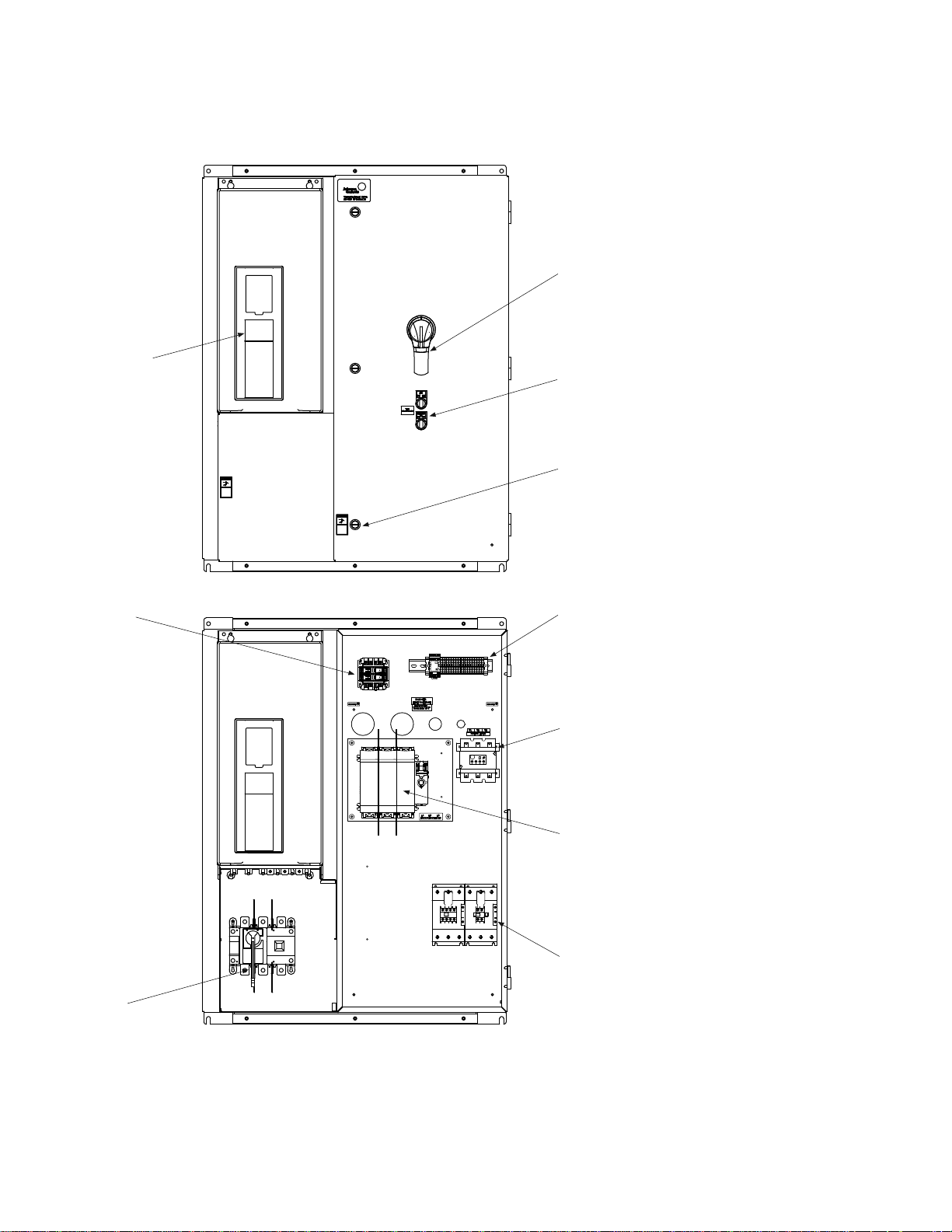
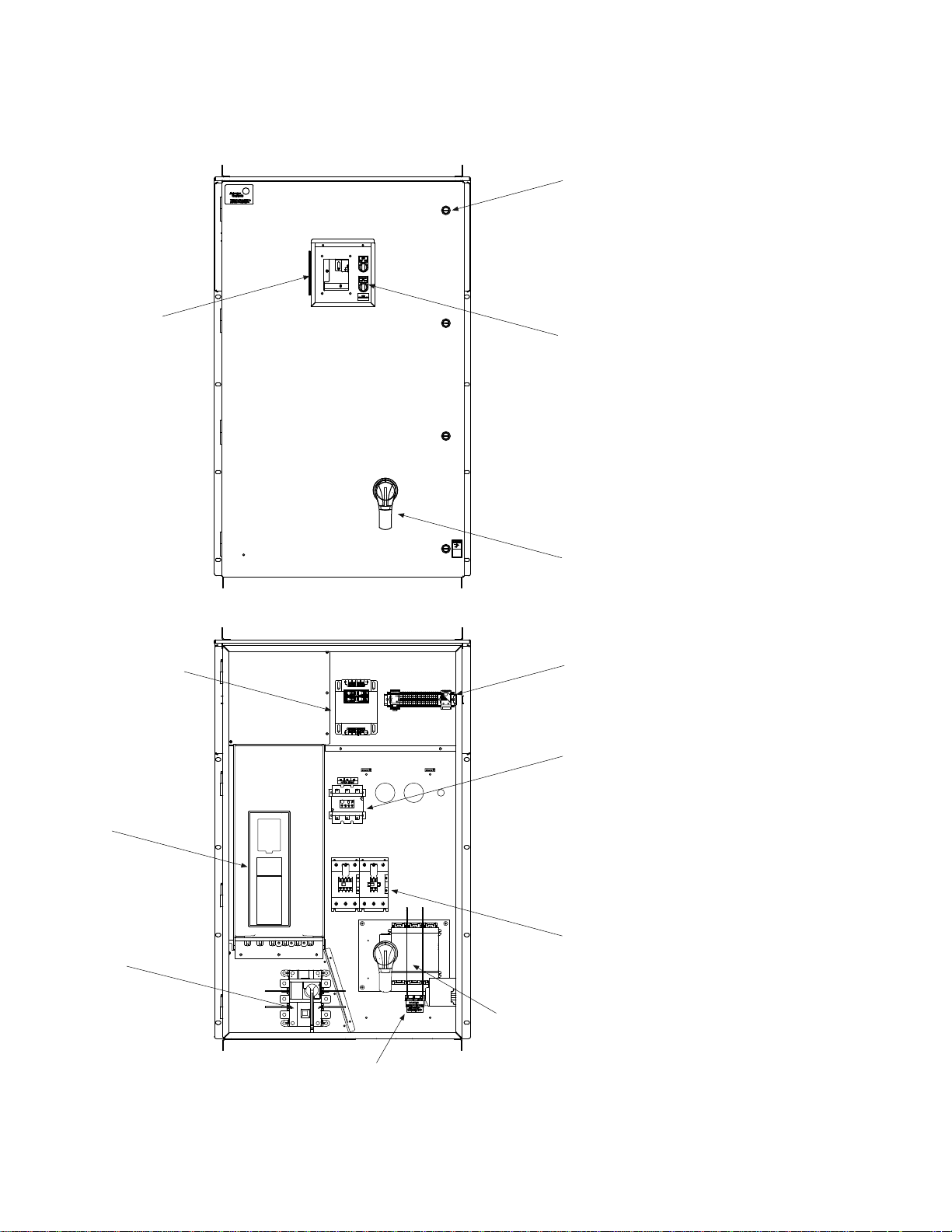
Component diagrams
JC-VSD Series II
Lockout
disconnect
handle
Quarter turn latches
Fused disconnect
with fuse holder
IntelliPass and IntelliDisconnect—typical component locations
Figure 4. Type 1 IntelliDisconnect
Component diagrams
Johnson Controls Variable Speed Drives LIT-12012114—July 2015 www.johnsoncontrols.com 3
Page 11
Component diagrams
JC-VSD Series II
Quarter turn latches
Cover controls
Lockout
disconnect
handle
Terminal
block access
Overload
protection relay
Fused disconnect
with fuse holder
Bypass and
drive contactor
Isolation
disconnect
Control power
transformer
Figure 5. Type 1 IntelliPass
4 Johnson Controls Variable Speed Drives LIT-12012114—July 2015 www.johnsoncontrols.com
Page 12
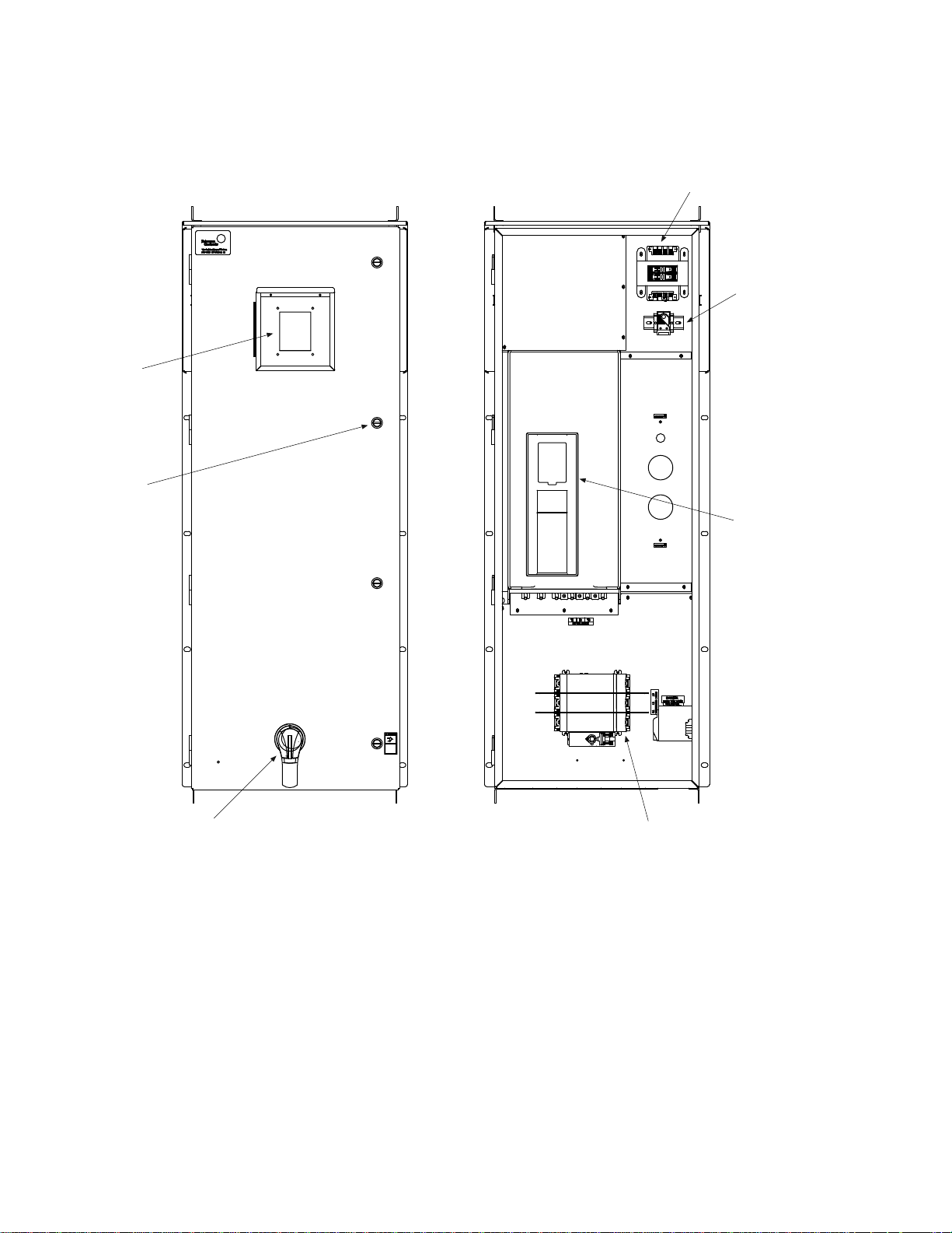
Figure 6. Type 3R IntelliDisconnect
Remote
mount
keypad
Quarter
turn
latches
Lockable
disconnect handle
Disconnect with
fuse holders
JC-VSD
Series II
Heater
Control
power transformer
Component diagrams
Johnson Controls Variable Speed Drives LIT-12012114—July 2015 www.johnsoncontrols.com 5
Page 13
Component diagrams
Cover controls
Quarter turn latches
Lockable
disconnect handle
Terminal
block access
Overload
protection relay
Bypass and
drive contactor
Disconnect with
fuse holder
Heater
Remote
mount keypad
Isolation
disconnect
JS-VSD
Series II
Control power
transformer
Figure 7. Type 3R IntelliPass
6 Johnson Controls Variable Speed Drives LIT-12012114—July 2015 www.johnsoncontrols.com
Page 14
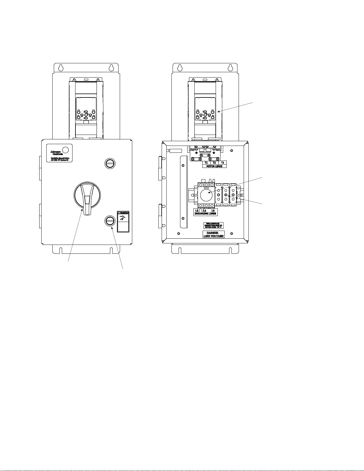
Figure 8. Type 1 Micro Disconnect
Lockable
disconnect handle
Quarter turn
latches
Fuse holder
Disconnect
JS-VSD Series II
Micro
Component diagrams
Johnson Controls Variable Speed Drives LIT-12012114—July 2015 www.johnsoncontrols.com 7
Page 15
Standard factory wired components
Standard factory wired components
The IntelliPass and IntelliDisconnect have the following
factory installed options. Any additional option are sold
separately. See part numbering matrix for ordering
information.
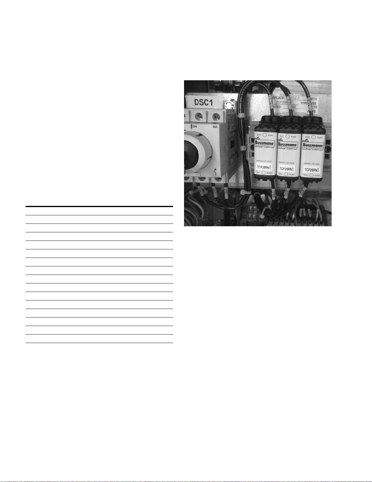
Drive isolation fuses
This option is available for both the IntelliPass and
IntelliDisconnect Fused Disconnect designs 208/230 V up
to 50 hp and 480 V models up to 125 hp.
Three power fuses are supplied wired to the drive input.
They are provided between the disconnect device and drive.
The fuses are not used in the bypass mode. The fuses are for
drive protection only. They are listed in the following table
and the Type J are sized according. See IntelliDisconnect or
Typical IntelliPass schematic.
Table 1. hp rating and fuse rating (A)
hp 208 V fuse 230 V fuse 460 V fuse
110106
2202010
3252510
5303020
7.5606025
10 60 60 30
15 60 100 30
20 100 100 60
25 100 100 60
30 200 200 60
40 200 200 125
50 200 200 150
60 N/A N/A 175
75 N/A N/A 200
100 N/A N/A 200
125 N/A N/A 200
Figure 9. Fused disconnect
8 Johnson Controls Variable Speed Drives LIT-12012114—July 2015 www.johnsoncontrols.com
Page 16
Standard factory wired components
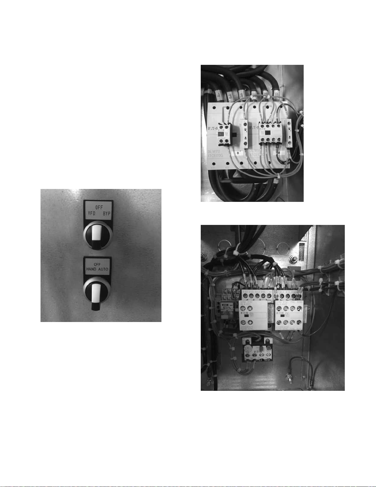
Manual bypass switch
This option is available on the IntelliPass models only. This
option includes a 3-position door mounted selector switch—
marked VFD / OFF / BYP. This switch manually overrides the
bypass control from the system (keypad) and puts unit in
bypass. See typical IntelliPass schematic.
When the door switch is in the drive position, the JC-VSD
Series II Drive logic controls the motor and the keypad
selects the operation (drive or bypass), the control source
and place (HOA, KEYPAD, or Terminal block).
When the door switch is moved to bypass, the drive output
contactor will be forced open and the bypass contactor will
be forced closed. The motor will immediately start and run
full speed across the line regardless of the state of the
system or drive. The keypad display will show “Bypass”.
When the switch is moved back to the drive position, drive
operation is restored after a system restart.
Figure 10. Door 3-position switches
Figure 11. Larger framed bypass contactor
Figure 12. Lower framed bypass contactor
Johnson Controls Variable Speed Drives LIT-12012114—July 2015 www.johnsoncontrols.com 9
Page 17

Standard factory wired components
Space heater
Type 3R enclosures only
This option aids in preventing or reducing condensation
from forming in the enclosure when the drive is inactive.
See selection table below for the size of heater that is
installed in each enclosure size. A control transformer
and fusing is also provided to power the heater. See
schematics for more information. The heater includes
a user adjustable thermostat for variable temperature
control and an internal fan.
Table 2. Space heater
Type 3R
IntelliDisconnect
enclosure size
C1 150 D1 150
C2 150 D2 150
C3 150 D3 150
C4 150 D4 250
C5 250 D5 250
C6 250 D6 250
Heater size
(W)
120 V rated
Type 3R
IntelliPass
enclosure size
Heater size
(W)
120 V rated
Setting the thermostat
The heater is controlled by an adjustable thermostat. Set the
thermostat to the desired temperature. It is recommended
not to exceed 75 °F for most applications. The heater is
active at all times when the main disconnect is closed
including when in the Drive, Off, or Bypass operation.
However, depending on the setting of the thermostat, the
internal heat generated by the system when in operation
should be enough to turn off the heater. Generally the heater
requires no maintenance because the fan bearings are
permanently lubricated and sealed.
10 Johnson Controls Variable Speed Drives LIT-12012114—July 2015 www.johnsoncontrols.com
Page 18

Standard factory wired components
Plug-in options
Auxiliary contacts (bypass only)
The bypass and drive contactor come installed with auxiliary
contacts. The configuration is used for bypass operation.
There are open NO and NC contacts on each the bypass and
drive contactor that can be used for customer use. See table
below for open contact configuration based on voltage and
horsepower.
Table 3. Auxiliary contacts (bypass only)
Bypass contactor (B) Drive contactor (M)
Voltage hp rating
208 / 203 V 1–4 B 1 1 N/A 1 NO is wired to terminal
5–10 C 1 1
15–20 D N/A 1
25–30 F N/A 1
40–50 G N/A 1
480 V 1–7.5 B 1 1
10–20 C 1 1
25–40 D N/A 1
50–60 F N/A 1
75–125 G N/A 1
Contactor
frame
Number of NC
available
Number of NO
available
Number of NC
available
Number of NO
available
block access 23 / 24
Johnson Controls Variable Speed Drives LIT-12012114—July 2015 www.johnsoncontrols.com 11
Page 19
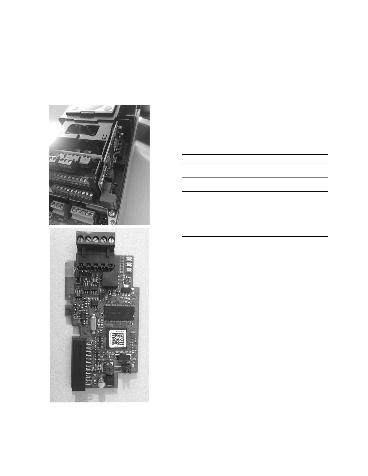
Standard factory wired components
Option PCB cards
A number of plug-in cards are available to expand I/O and
communications. The SA Bus communication card is the only
factory installed option. Reference the catalog matrix for
ordering. All other cards are sold separately.
Figure 13. Option PCB cards
High temperature option
For NEMA Type 3R enclosures, vent covers are shipped
loose inside the enclosure. These vent covers would need to
be installed when the high temperature option is utilized. The
vent cover would be installed on the outside bottom of the
enclosure to cover the vents.
Also see JC-VSD Series II Installation Manual LIT-12011772
for more information on control wiring, control board layout
and option PCBs.
Table 4. Option PCB cards
Part number Description
VS-XMX-B1 I/O Expander Card, 6 DI/DO, Slot D/E VS-XMX-B1
VS-XMX-B2 I/O Expander Card 2 x RO + Thermistor, Slot D/E
VS-XMX-B4 I/O Expander Card 1 x AI, 2 x AO (isolated), Slot D/E
VS-XMX-B5 I/O Expander Card 3 x RO, Slot D/E VS-XMX-B5
VS-XMX-B9 I/O Expander Card 1 x RO, 5 x DI (42-240VAC), Slot D/E
VS-XMX-BF I/O expander Card, 1 x AO, 1 x DO, 1 x RO, Slot D/E
VS-XMX-C4 lonworks
VS-XMX-CS SA Bus, slot D/E
VS-XMX-B2
VS-XMX-B4
VS-XMX-B9
VS-XMX-BF
®
, Slot D/E VS-XMX-C4
12 Johnson Controls Variable Speed Drives LIT-12012114—July 2015 www.johnsoncontrols.com
Page 20

Dimensions and mounting
Dimensions and mounting
The IntelliPass / IntelliDisconnect physical dimensions are
based on the enclosure frame size. See following table to
determine the enclosure frame size based on horsepower
and voltage.
●
Weights and lifting provisions are on the dimension section
and with the drawing provided with the unit
●
Attach “load-rated” hooks or shackles to lifting eyes on
back panel
●
Always maintain a maximum of 45 degrees between the
The hardware to mount the Intellipass / IntelliDisconnect
units, all frame sizes, is as follows:
●
3/8-16 Grade 5 Hex Head Bolt, with 3/8 lock washer and
3/8 flat washer. QTY 4 of each required. Torque to 20 lb-ft
Use the tables below to determine enclosure size and
frame size based on voltage and horsepower. Enclosure
dimensions differ between Type 1 IntelliDisconnect, Type
1 IntelliPass, Type 3R IntelliDisconnect, Type 3R IntelliPass,
Type 1 Micro Disconnect.
lifting cables and the vertical plane
●
Do not pass ropes or cables through the lifting eyes as
sharp edges may cause excessive wear and possible
failure
●
Select or adjust rigging lengths to compensate for unequal
weight distribution of the load to keep unit in the upright
position
Table 5. Enclosure size and frame size based on voltage and horsepower (208/230 V)
hp Base drive Type 1 disconnect Type 1 bypass Type 3R disconnect Type 3R bypass
1 FS4 A1-4 B1-4 C1-4 D1-4
2 FS4 A1-4 B1-4 C1-4 D1-4
3 FS4 A1-4 B1-4 C1-4 D1-4
5 FS5 A1-5 B1-5 C1-5 D1-5
7.5 FS5 A2-5 B2-5 C2-5 D2-5
10 FS5 A2-5 B2-5 C2-5 D2-5
15 FS6 A3-6 B3-6 C3-6 D3-6
20 FS6 A3-6 B3-6 C3-6 D3-6
25 FS7 A4-7 B4-7 C4-7 D4-7
30 FS7 A4-7 B4-7 C4-7 D4-7
40 FS7 A4-8 B4-8 C4-8 D4-8
50 FS8 A6-8 B6-8 C6-8 D6-8
60FS8————
75FS8————
Johnson Controls Variable Speed Drives LIT-12012114—July 2015 www.johnsoncontrols.com 13
Page 21

Dimensions and mounting
Table 6. Enclosure size and frame size based on voltage and horsepower (480 V)
hp Base drive Type 1 disconnect Type 1 bypass Type 3R disconnect Type 3R bypass
1 FS4 A1-4 B1-4 C1-4 D1-4
2 FS4 A1-4 B1-4 C1-4 D1-4
3 FS4 A1-4 B1-4 C1-4 D1-4
5 FS4 A1-4 B1-4 C1-4 D1-4
7.5 FS4 A1-4 B1-4 C1-4 D1-4
10 FS5 A2-5 B2-5 C2-5 D2-5
15 FS5 A2-5 B2-5 C2-5 D2-5
20 FS5 A3-5 B3-5 C3-5 D3-5
25 FS6 A3-6 B3-6 C3-6 D3-6
30 FS6 A3-6 B3-6 C3-6 D3-6
40 FS6 A4-6 B4-6 C4-6 D4-6
50 FS7 A4-7 B4-7 C4-7 D4-7
60 FS7 A4-7 B4-7 C4-7 D4-7
75 FS7 A4-7 B4-7 C4-7 D4-7
100 FS8 A5-8 B5-8 C5-8 D5-8
125 FS8 A6-8 B6-8 C6-8 D6-8
Table 7. Type 1 Micro Disconnect
hp 208/230 V 480 V
0.5 M1-1 M1-1
0.75 M1-2 M1-1
1 M1-2 M1-1
1.5 M1-2 M1-2
2— M1-2
14 Johnson Controls Variable Speed Drives LIT-12012114—July 2015 www.johnsoncontrols.com
Page 22

Figure 14. Type 1 IntelliDisconnect dimensions
H
W
D
D1
H1
W1
Dimensions and mounting
Table 8. Type 1 IntelliDisconnect dimensions
Approximate dimensions in inches (mm)
Enclosure size—
drive frame size H H1 W W1 D D1
Weight in
lb (kg)
A1-4 20.61 (523.5) 19.75 (501.7) 8.65 (219.7) 6.75 (171.5) 10.40 (264.2) 8.96 (227.6) 34 (15)
A1-5 30.00 (762.0) 29.00 (736.6) 8.65 (219.7) 6.75 (171.5) 11.18 (284.0) 9.74 (247.4) 54 (25)
A2-5 30.00 (762.0) 29.00 (736.6) 8.65 (219.7) 6.75 (171.5) 11.18 (284.0) 9.74 (247.4) 54 (25)
A3-5 20.61 (523.5) 19.75 (501.7) 8.65 (219.7) 6.75 (171.5) 10.40 (264.2) 8.96 (227.6) 54 (25)
A3-6 32.50 (825.5) 31.50 (800.1) 10.40 (264.2) 7.50 (190.5) 11.41 (289.8) 9.97 (253.2) 101 (46)
A4-6 41.03 (1042.2) 39.50 (1003.3) 12.40 (315.0) 10.50 (266.7) 13.67 (347.2) 11.97 (304.0) 113 (51)
A4-7 41.55 (1055.4) 39.50 (1003.3) 12.40 (315.0) 10.50 (266.7) 13.94 (354.1) 12.25 (311.2) 200 (91)
A4-8 44.04 (1118.6) 39.50 (1003.3) 12.00 (304.8) 10.50 (266.7) 15.86 (402.8) 14.17 (359.9) 363 (165)
A5-8 44.05 (1118.9) 42.06 (1068.3) 12.00 (304.8) 10.50 (266.7) 15.86 (402.8) 14.17 (359.9) 363 (165)
A6-8 47.65 (1210.3) 46.50 (1181.1) 16.00 (406.4) 14.50 (368.3) 15.86 (402.8) 14.17 (359.9) 363 (165)
Johnson Controls Variable Speed Drives LIT-12012114—July 2015 www.johnsoncontrols.com 15
Page 23

Dimensions and mounting
F
A
5
4
3
21
E
D
B
C
C
A
B
F
E
D
G
3
2
1
4
5
Figure 15. Type 1 IntelliDisconnect knockout dimensions
Table 9. Type 1 IntelliDisconnect knockout dimensions
Approximate dimensions in inches (mm)
Enclosure
sizeABCDE FG
A1-4 1.12 (28.4) 3.74 (95.0) 4.24 (17.7) 4.77 (121.2) 6.27 (159.3) 7.77 (197.4) 0.875 1.109 & 0.875
A1-5 1.12 (28.4) 3.74 (95.0) 4.24 (17.7) 5.55 (141.0) 7.05 (179.1) 8.55 (217.2) 0.875 1.109 & 0.875
A2-5 1.12 (28.4) 3.74 (95.0) 4.24 (17.7) 5.55 (141.0) 7.05 (179.1) 8.55 (217.2) 0.875 1.109 & 0.875
A3-5 1.12 (28.4) 3.74 (95.0) 4.24 (17.7) 4.77 (121.2) 6.27 (159.3) 7.77 (197.4) 0.875 1.375 & 1.109
A3-6 1.00 (25.4) 3.63 (92.2) 5.03 (127.8) 5.79 (147.1) 7.29 (185.2) 8.79 (223.3) 0.875 1.375 & 1.109
A4-6 1.55 (39.4) 1.55 (39.4) 7.67 (194.8) 5.99 (152.1) 7.74 (196.6) 9.24 (234.7) 10.74 (272.8) 0.875 1.735 & 1.375
A4-7 1.55 (39.4) 1.55 (39.4) 7.67 (194.8) 6.27 (159.3) 8.02 (203.7) 9.52 (241.8) 11.02 (280.0) 0.875 1.735 & 1.375
A4-8 2.47 (62.7) 3.47 (88.1) 8.47 (215.1) 5.96 (151.4) 9.58 (243.3) 11.08 (281.4) 12.58 (319.5) 0.875 1.735 & 1.375
A5-8 2.53 (64.3) 3.53 (89.7) 8.53 (216.7) 5.96 (151.4) 9.58 (243.3) 11.08 (281.4) 12.58 (319.5) 0.875 1.984 & 1.734
A6-8 4.53 (115.1) 5.53 (140.5) 10.53 (267.5) 5.96 (151.4) 9.58 (243.3) 11.08 (281.4) 12.58 (319.5) 0.875 1.984 & 1.734
Conduit
1, 2 & 3
Conduit
4 & 5
16 Johnson Controls Variable Speed Drives LIT-12012114—July 2015 www.johnsoncontrols.com
Page 24

Figure 16. Type 1 IntelliPass dimensions
D1
W
W1
H1
H
D
Dimensions and mounting
Table 10. Type 1 IntelliPass dimensions
Approximate dimensions in inches (mm)
Enclosure size—
drive frame size H H1 W W1 D D1
Weight in
lb (kg)
B1-4 23.00 (584.2) 21.75 (552.5) 16.28 (413.5) 14.75 (374.7) 15.70 (398.8) 14.26 (362.2) 64 (29)
B1-5 23.00 (584.2) 21.75 (552.5) 16.28 (413.5) 14.75 (374.7) 15.70 (398.8) 14.26 (362.2) 88 (40)
B2-5 30.00 (762.0) 29.00 (736.6) 16.28 (413.5) 14.75 (374.7) 15.70 (398.8) 14.26 (362.2) 88 (40)
B3-5 31.50 (800.1) 30.50 (774.7) 19.13 (485.9) 17.75 (450.9) 15.70 (398.8) 14.26 (362.2) 88 (40)
B3-6 31.50 (800.1) 30.50 (774.7) 19.13 (485.9) 17.75 (450.9) 15.70 (398.8) 14.26 (362.2) 145 (66)
B4-6 39.50 (1003.3) 38.25 (971.6) 30.13 (765.3) 28.75 (730.3) 17.42 (442.5) 15.73 (399.5) 158 (72)
B4-7 42.75 (1085.9) 38.25 (971.6) 30.13 (765.3) 28.75 (730.3) 17.42 (442.5) 15.73 (399.5) 262 (119)
B4-8 42.90 (1089.7) 38.25 (971.6) 30.13 (765.3) 28.75 (730.3) 17.42 (442.5) 15.73 (399.5) 455 (207)
B5-8 44.00 (1117.6) 42.75 (1085.9) 33.13 (841.5) 31.75 (806.5) 17.42 (442.5) 15.73 (399.5) 455 (207)
B6-8 44.00 (1117.6) 42.75 (1085.9) 33.13 (841.5) 31.75 (806.5) 17.42 (442.5) 15.73 (399.5) 455 (207)
Johnson Controls Variable Speed Drives LIT-12012114—July 2015 www.johnsoncontrols.com 17
Page 25

Dimensions and mounting
D
C
A
1
2
3
4
5
B
6
E
F
G
H
Figure 17. Type 1 IntelliPass knockout dimensions
Table 11. Type 1 IntelliPass knockout dimensions
Approximate dimensions in inches (mm)
Enclosure size—
drive frame size A B C D Conduit 1 Conduit 2 Conduit 3
B1-4 1.75 (44.5) 4.75 (120.7) 7.75 (196.9) 9.70 (246.4) 1.109 1.109 1.375 & 1.109
B1-5 1.75 (44.5) 4.75 (120.7) 7.75 (196.9) 9.70 (246.4) 1.109 1.109 1.375 & 1.109
B2-5 1.75 (44.5) 4.75 (120.7) 7.75 (196.9) 9.78 (248.4) 1.109 1.109 1.375 & 1.109
B3-5 2.13 (54.1) 5.13 (130.3) 8.13 (206.5) 9.78 (248.4) 1.109 1.109 1.984 & 1.109
B3-6 2.13 (54.1) 5.13 (130.3) 8.13 (206.5) 9.78 (248.4) 1.109 1.109 1.984 & 1.109
B4-6 6.15 (156.2) 10.15 (257.8) 14.00 (255.6) 10.26 (260.6) 1.109 1.109 1.964 & 1.109
B4-7 6.15 (156.2) 10.15 (257.8) 14.00 (255.6) 10.26 (260.6) 1.109 1.109 1.964 & 1.109
B4-8 6.15 (156.2) 10.15 (257.8) 14.00 (255.6) 10.26 (260.6) 1.109 1.109 1.964 & 1.109
B5-8 6.09 (154.7) 11.09 (281.7) 16.09 (408.7) 10.11 (256.8) 1.375 2.469 & 1.984 2.469 & 1.984
B6-8 6.09 (154.7) 11.09 (281.7) 16.09 (408.7) 10.11 (256.8) 1.375 2.469 & 1.984 2.469 & 1.984
Enclosure size—
drive frame size E F G H Conduit 4 Conduit 5 Conduit 6
B1-4 1.83 (46.5) 4.83 (122.7) 7.83 (198.9) 10.26 (260.6) 1.109 1.109 1.375 & 1.109
B1-5 1.83 (46.5) 4.83 (122.7) 7.83 (198.9) 10.26 (260.6) 1.109 1.109 1.375 & 1.109
B2-5 1.75 (44.5) 4.75 (120.7) 7.75 (196.9) 9.78 (248.4) 1.109 1.109 1.375 & 1.109
B3-5 2.13 (54.1) 5.13 (130.3) 8.13 (206.5) 9.78 (248.4) 1.109 1.109 1.984 & 1.109
B3-6 2.13 (54.1) 5.13 (130.3) 8.13 (206.5) 9.78 (248.4) 1.109 1.109 1.984 & 1.109
B4-6 6.09 (154.7) 10.08 (256.0) 14.00 (255.6) 10.11 (256.8) 1.109 1.109 1.964 & 1.109
B4-7 6.09 (154.7) 10.08 (256.0) 14.00 (255.6) 10.11 (256.8) 1.109 1.109 1.964 & 1.109
B4-8 6.09 (154.7) 10.08 (256.0) 14.00 (255.6) 10.11 (256.8) 1.109 1.109 1.964 & 1.109
B5-8 6.09 (154.7) 11.09 (281.7) 16.09 (408.7) 10.11 (256.8) 1.375 2.469 & 1.984 2.469 & 1.984
B6-8 6.09 (154.7) 11.09 (281.7) 16.09 (408.7) 10.11 (256.8) 1.375 2.469 & 1.984 2.469 & 1.984
18 Johnson Controls Variable Speed Drives LIT-12012114—July 2015 www.johnsoncontrols.com
Page 26

Figure 18. Type 3R IntelliDisconnect dimensions
H5
W
H
D1
D
H4
H2
H3
W1
H1
Dimensions and mounting
Table 12. Type 3R IntelliDisconnect dimensions
Approximate dimensions in inches (mm)
Enclosure size—
drive frame size H H1 H2 H3 H4 H5 W W1 D D1
C1-4 22.79
(578.9)
C1-5 22.79
(578.9)
C2-5 29.79
(756.7)
C3-5 31.72
(805.7)
C3-6 31.72
(805.7)
C4-6 53.67
(1363.2)
C4-7 53.67
(1363.2)
C4-8 53.67
(1363.2)
C5-8 53.67
(1363.2)
C6-8 53.67
(1363.2)
3.75
(95.25)
3.75
(95.25)
4.10
(104.1)
0.70
(17.78)
0.70
(17.78)
3.37
(85.6)
3.37
(85.6)
3.37
(85.6)
1.87
(47.5)
2.20
(55.9)
11.25
(285.8)
11.25
(285.8)
14.10
(358.1)
9.87
(250.7)
9.87
(250.7)
12.87
(326.9)
12.87
(326.9)
12.87
(326.9)
11.87
(301.5)
13.95
(354.3)
18.75
(476.25)
18.75
(476.25)
24.10
(612.1)
19.03
(483.4)
19.03
(483.4)
22.37
(568.2)
22.37
(568.2)
22.37
(568.2)
21.87
(555.5)
25.70
(652.8)
— — 15.13
(384.3)
— — 15.13
(384.3)
-— — 15.13
(384.3)
28.20
(716.3)
28.20
(716.3)
31.87
(809.5
31.87
(809.5)
31.87
(809.5)
31.87
(809.5)
37.45
(951.2)
— 18.13
-— 18.13
41.37
)
(1050.8)
41.37
(1050.8)
41.37
(1050.8)
41.37
(1050.8)
49.20
(1249.7)
(460.5)
(460.5)
17.63
(447.8
17.63
(447.8)
17.63
(447.8)
21.38
(543.1)
22.88
(581.2)
14.19
(360.4)
14.19
(360.4)
14.19
(360.4)
17.19
(436.6)
17.19
(436.6)
16.61
)
(421.9)
16.61
(421.9)
16.61
(421.9)
20.36
(517.1)
21.86
(555.2)
14.24
(361.7)
14.24
(361.7)
14.24
(361.7)
14.24
(361.7)
14.24
(361.7)
16.11
(409.2)
16.11
(409.2)
18.11
(460.0)
18.11
(460.0)
21.11
(539.2)
11.48
(291.6)
11.48
(291.6)
11.48
(291.6)
11.48
(291.6)
11.48
(291.6)
13.36
(339.3)
13.36
(339.3)
15.36
(390.1)
15.36
(390.1)
18.36
(466.3)
Weight in
lb (kg)
46 (21)
63 (29)
66 (30)
66 (30)
113 (51)
128 (58)
226 (103)
378 (172)
405 (184)
405 (184)
Johnson Controls Variable Speed Drives LIT-12012114—July 2015 www.johnsoncontrols.com 19
Page 27

Dimensions and mounting
D
B
1
2
3
C
A
Figure 19. Type 3R IntelliDisconnect knockout dimensions
Table 13. Type 3R IntelliDisconnect knockout dimensions
Approximate dimensions in inches (mm)
Enclosure size—
drive frame size A B C D Conduit 1 Conduit 2 Conduit 3
C1-4 4.99 (126.7) 7.99 (202.9) 10.99 (279.1) 6.07 (154.2) 1.375 & 1.109 1.109 1.109
C1-5 4.99 (126.7) 7.99 (202.9) 10.99 (279.1) 6.07 (154.2) 1.375 & 1.109 1.109 1.109
C2-5 4.99 (126.7) 7.99 (202.9) 10.99 (279.1) 6.57 (166.9) 1.375 & 1.109 1.109 1.109
C3-5 7.99 (202.9) 10.99 (279.1) 13.99 (355.3) 6.57 (166.9) 1.109 1.109 1.734 & 1.109
C3-6 7.99 (202.9) 10.99 (279.1) 13.99 (355.3) 6.57 (166.9) 1.109 1.109 1.734 & 1.109
C4-6 6.49 (164.8) 9.49 (241.0) 12.49 (317.2) 7.58 (192.5) 1.984 & 1.109 1.109 1.109
C4-7 6.49 (164.8) 9.49 (241.0) 12.49 (317.2) 7.58 (192.5) 1.984 & 1.109 1.109 1.109
C4-8 6.49 (164.8) 9.49 (241.0) 12.49 (317.2) 7.58 (192.5) 1.984 & 1.109 1.109 1.109
C5-8 6.24 (158.5) 10.74 (272.8) 15.24 (387.1) 8.08 (205.2) 2.469 & 1.948 2.469 & 1.948 1.375
C6-8 7.74 (196.6) 12.24 (310.9) 16.74 (425.2) 11.08 (281.4) 2.469 & 1.984 2.469 & 1.984 1.375
20 Johnson Controls Variable Speed Drives LIT-12012114—July 2015 www.johnsoncontrols.com
Page 28

Figure 20. Type 3R IntelliPass dimensions
H5
W
H
D1
D
H4
H2
H3
W1
H1
Dimensions and mounting
Table 14. Type 3R IntelliPass dimensions
Approximate dimensions in inches (mm)
Enclosure size—
drive frame size H H1 H2 H3 H4 H5 W W1 D D1
D1-4 22.87
(580.9)
D1-5 22.87
(580.9)
D2-5 22.87
(580.9)
D3-5 30.74
(780.8)
D3-6 30.74
(780.8)
D4-6 48.67
(1236.2)
D4-7 48.67
(1236.2)
D4-8 48.67
(1236.2)
D5-8 48.67
(1236.2)
D6-8 50.17
(1274.3)
1.25
(31.8)
1.25
(31.8)
1.00
(25.4)
3.25
(82.6)
3.25
(82.6)
1.75
(44.5)
1.75
(44.5)
1.75
(44.5)
2.00
(50.8)
2.00
(50.8)
8.75
(222.3)
8.75
(222.3)
8.50
(215.9)
13.25
(336.6)
13.25
(336.6)
10.25
(260.4)
10.25
(260.4)
10.25
(260.4)
11.50
(292.1)
13.00
(330.2)
16.25
(412.8)
16.25
(412.8)
16.00
(406.4)
23.25
(590.6)
23.25
(590.6)
18.75
(476.3)
18.75
(476.3)
18.75
(476.3)
21.00
(533.4)
24.00
(609.6)
— — 18.13
(460.5)
— — 18.13
(460.5)
— — 18.13
(460.5)
— — 21.13
(536.7)
— — 21.13
(536.7)
27.25
(692.2)
27.25
(692.2)
27.25
(692.2)
30.50
(774.7)
35.00
(889.0)
35.75
(908.1)
35.75
(908.1)
35.75
(908.1)
40.00
(1016.0)
46.00
(1168.4)
28.13
(714.5
28.13
(714.5)
28.13
(714.5)
32.13
(816.1)
32.13
(816.1)
17.19
(436.6)
17.19
(436.6)
17.19
(436.6)
20.19
(512.8)
20.19
(512.8)
27.11
)
(688.6)
27.11
(688.6)
27.11
(688.6)
31.19
(792.2)
31.19
(792.2)
17.23
(437.6)
17.23
(437.6)
17.23
(437.6)
17.23
(437.6)
17.23
(437.6)
18.11
(460.0)
18.11
(460.0)
18.11
(460.0)
22.11
(561.6)
22.11
(561.6)
14.48
(367.8)
14.48
(367.8)
14.48
(367.8)
14.48
(367.8)
14.48
(367.8)
15.36
(3
90.1)
15.36
(390.1)
15.36
(390.1)
19.36
(491.7)
19.36
(491.7)
Weight in
lb (kg)
80 (36)
104 (47)
104 (47)
104 (47)
164 (74)
183 (83)
291 (132)
485 (220)
526 (239)
532 (242)
Johnson Controls Variable Speed Drives LIT-12012114—July 2015 www.johnsoncontrols.com 21
Page 29

Dimensions and mounting
D
B
1
2
3
C
A
Figure 21. Type 3R IntelliPass knockout dimensions
Table 15. Type 3R IntelliPass knockout dimensions
Approximate dimensions in inches (mm)
Enclosure size—
drive frame size A B C D Conduit 1 Conduit 2 Conduit 3
D1-4 4.06 (103.1) 7.06 (179.3) 10.06 (255.5) 9.62 (244.3) 1.109 1.109 1.375 & 1.109
D1-5 4.06 (103.1) 7.06 (179.3) 10.06 (255.5) 9.62 (244.3) 1.109 1.109 1.375 & 1.109
D2-5 4.06 (103.1) 7.06 (179.3) 10.06 (255.5) 9.62 (244.3) 1.109 1.109 1.375 & 1.109
D3-5 4.06 (103.1) 7.06 (179.3) 10.06 (255.5) 9.62 (244.3) 1.109 1.109 1.375 & 1.109
D3-6 4.06 (103.1) 7.06 (179.3) 10.06 (255.5) 9.62 (244.3) 1.109 1.109 1.375 & 1.109
D4-6 6.06 (153.9) 10.56 (268.2) 15.06 (382.5) 11.13 (282.7) 1.109 1.109 1.984 & 1.109
D4-7 6.06 (153.9) 10.56 (268.2) 15.06 (382.5) 11.13 (282.7) 1.109 1.109 1.984 & 1.109
D4-8 6.06 (153.9) 10.56 (268.2) 15.06 (382.5) 11.13 (282.7) 1.109 1.109 1.984 & 1.109
D5-8 6.06 (153.9) 10.56 (268.2) 15.06 (382.5) 11.13 (282.7) 1.375 2.469 & 1.984 2.469 & 1.984
D6-8 6.06 (153.9) 10.56 (268.2) 15.06 (382.5) 11.13 (282.7) 1.375 2.469 & 1.984 2.469 & 1.984
22 Johnson Controls Variable Speed Drives LIT-12012114—July 2015 www.johnsoncontrols.com
Page 30

Figure 22. Type 1 Micro Disconnect dimensions
H1
D1
D
W
W1
H
Dimensions and mounting
Table 16. Type 1 Micro Disconnect dimensions
Approximate dimensions in inches (mm)
Enclosure size—
drive frame size H H1 W W1 D D1
Weight in
lb (kg)
M1-1 19.78 (502.4) 19.03 (483.4) 9.59 (243.6) 5.25 (133.4) 8.61 (218.7) 7.19 (182.6) 13.9 (6.3)
M1-2 19.78 (502.4) 19.03 (483.4) 9.59 (243.6) 5.25 (133.4) 8.61 (218.7) 7.19 (182.6) 15.4 (7.0)
Johnson Controls Variable Speed Drives LIT-12012114—July 2015 www.johnsoncontrols.com 23
Page 31

Dimensions and mounting
A
C
1
23
4
B
D
E
F
Figure 23. Type 1 Micro Disconnect knockout dimensions
Table 17. Type 1 Micro Disconnect knockout dimensions
Approximate dimensions in inches (mm)
Enclosure size—
drive frame size A B C D E F Conduit 1, 2, 3 & 4
M1-1 4.28 (108.7) 5.78 (146.8) 3.28 (83.3) 3.78 (96.0) 4.78 (121.4) 7.90 (200.7) 1.125 & 0.875
M1-2 4.28 (108.7) 5.78 (146.8) 3.28 (83.3) 3.78 (96.0) 4.78 (121.4) 7.90 (200.7) 1.125 & 0.875
24 Johnson Controls Variable Speed Drives LIT-12012114—July 2015 www.johnsoncontrols.com
Page 32

Wiring
Wiring schematic
A schematic is included with each product. The schematic
number can be found on the product nameplate.
Typical schematics are shown on the next few pages.
Notes
●
Power and motor leads must be in separate conduit
●
Do not run control wires in same conduit as input power
or motor wires
●
Two grounding points are provided, input ground and
output ground
●
Ground unit properly – improper grounding could
damage the unit
Wiring
Johnson Controls Variable Speed Drives LIT-12012114—July 2015 www.johnsoncontrols.com 25
Page 33

Wiring
Figure 24. Type 1 IntelliDisconnect
26 Johnson Controls Variable Speed Drives LIT-12012114—July 2015 www.johnsoncontrols.com
Page 34

Figure 25. Type 1 IntelliPass
Wiring
Johnson Controls Variable Speed Drives LIT-12012114—July 2015 www.johnsoncontrols.com 27
Page 35

Wiring
Figure 26. Type 3R IntelliDisconnect
28 Johnson Controls Variable Speed Drives LIT-12012114—July 2015 www.johnsoncontrols.com
Page 36

Figure 27. Type 3R IntelliPass
Wiring
Johnson Controls Variable Speed Drives LIT-12012114—July 2015 www.johnsoncontrols.com 29
Page 37

Wiring
Figure 28. Type 1 Micro Disconnect
30 Johnson Controls Variable Speed Drives LIT-12012114—July 2015 www.johnsoncontrols.com
Page 38

Wiring
Conduit plates
There are removable top and bottom conduit plates on drives
frames size 8 on designations A4, A5, and A6 (Type 1
IntelliDisconnect) configurations to allow for easier wiring
and conduit connections.
Input power wiring
Input power connection are made to the disconnect device.
Input power connection points are identified by Label (L1, L2,
and L3).
Both the IntelliDisconnect and IntelliPass systems provide an
input disconnect by using a UL Listed, R9 rotary disconnect
fusible or non-fusible as indicated below. These devices
provide a disconnect function and branch protection. In
non-fusible systems, the disconnect is paired with fused
for short circuit protections.
Figure 29. Lower frame incoming lines
Figure 30. Larger frame incoming lines
Input wiring details
Table 18. Input wiring
Voltage hp Wire range Torque (lb-in)
Non-fused disconnect type
208/230 V 1–5 #14–#10 25
7.5–10 #14–#10 28
15–20 #12–2/0 35
25 #6–300 kcmil 160
30–40 #6–300 kcmil 160
480 V 1–15 #14–#10 25
20–30 #14–#10 28
40–125 #6–300 kcmil 160
Fused disconnect type
208/230 V 1–5 #14–#10 25
7.5–10 #14–#10 28
15–20 #12–2/0 35
25 #12–#1 35
30–40 #6–3/0 200
480 V 1–15 #14–#10 25
20–30 #14–#10 28
40–125 #6–3/0 200
Johnson Controls Variable Speed Drives LIT-12012114—July 2015 www.johnsoncontrols.com 31
Page 39

Wiring
Motor wiring
Motor connection points are identified by a label (T1, T2,
and T3). See output wiring table in technical section for
wiring and torque information. For IntelliDisconnect models,
the motor wiring is direct to the drive output terminals. For
IntelliPass models, the motor wiring is directly to the output
of the overload protection relay on the bypass contactor.
Figure 31. IntelliDisconnect motor wiring
Figure 32. IntelliPass motor wiring
Table 19. Output wiring details—IntelliDisconnect
Voltage hp Drive frame size Torque (lb-in)
208/230 V 1–3 4 4.5
5–10 5 11
15–20 6 35
25–30 7 88
40–50 8 170
480 V 1–7.5 4 4.5
10–20 5 11
25–40 6 35
50–75 7 88
100–125 8 170
Micro
208/230/480 V 0.5–2 FS1 / FS2 4.5
Table 20. Output wiring details—IntelliPass
Voltage hp Torque (lb-in)
208/230 V 1–3 15
5–10 15
15–20 28
25–50 90
480 V 1–7.5 15
10–20 15
25–40 28
50–125 90
32 Johnson Controls Variable Speed Drives LIT-12012114—July 2015 www.johnsoncontrols.com
Page 40

Wiring
Ground wiring
Ground studs are provided and marked with label. Hardware
is also supplied.
Figure 33. Typical ground stud and label
Frames 1 through 5 have ground lugs supplied for wire size
14 to 2/0.
Frame 6 with drive frame size 8 has ground lugs supplied for
wire size 3/0.
Control wiring
All customer wiring points are supplied on a terminal block
strip. This terminal strip allows easy access to the drives
control terminals and auxiliary contacts. The control I/O
terminals must be tightened to 4.5 lb (0.5 Nm). Please see
table below for terminal block designation.
Figure 34. Terminal block access
Table 21. Terminal block designation
Terminal block Description
AI1 Analog Input Voltage (Range 0–10 Vdc)–2
COM Analog Input Common–3
AO1 Output Frequency–18
COM (AGND) Analog Output–19
SHD GND–7
15 Safety 3
16 Safety 3–Run Permissive IP Interlock–10
25 RO3 Drive Fault Output–32
27 RO3 Drive Fault Output–33
2 Run/Time Clock Start/Stop Command
3 Run/Time Clock Start/Stop Command
4 Electronic Bypass connection points
5 Electronic Bypass connection points
6 Electronic Bypass connection points
7 Safety 1 and 2 connection points
8 Safety 1 and 2 connection points
9 Safety 1 and 2 connection points
22 Drive Contactor (Run Output)–53
24 Drive Contactor (Run Output)–54
Johnson Controls Variable Speed Drives LIT-12012114—July 2015 www.johnsoncontrols.com 33
Page 41

Initial startup
Initial startup
When the IntelliPass or IntelliDisconnect is first powered up,
the Startup Wizard command should be displayed.
Figure 35. Startup Wizard prompt
Follow the Quick Setup guide LIT-12011773 to set up drive
for your specific application with the following exceptions:
When the Bypass screen appears, set it to “Enabled” for
IntelliPass models and “Disabled” for IntelliDisconnect
models.
Figure 36. Enable bypass for IntelliPass models
IntelliDisconnect operation
(starting/stopping of the motor)
IntelliDisconnect operation is the identical to a standard
JCI-VSD Series II open drive. The only difference is that an
input disconnect is provided. For more information on speed
control and other drive features, see Application Manual
LIT-12011771. See option sections for more information on
operation of IntelliDisconnect options, i.e., drive output
contactor.
IntelliPass operation
(starting/stopping of the motor)
The IntelliPass operation is similar to the IntelliDisconnect
but has the added feature of a built-in drive bypass. This
section gives basic information on operations for controlling
the starting and stopping of the motor in both the drive and
bypass modes. For more information on speed control and
other drive features, see Application Manual LIT-12011771.
The IntelliPass has 2 modes:
●
Drive mode (normal VFD operation)
●
Bypass mode (across the line)
The mode is selected via the keypad. The actual starting and
stopping of the motor is determined by the HOA selection
and the control place selections. The control place is defined
as the location from where the drive is started and stopped.
The control place can be: keypad start button, I/O contacts
wired to the logic terminal blocks, Fieldbus control or PC.
See Quick Start Guide LIT-12011775 or Application Manual
LIT-12011771 for more information.
The only exception is the use of the drive—bypass 3-position
switch for manual operation. This will override the drive logic
and can start the motor in Bypass immediately.
Switch operation
Figure 37. Disable bypass for IntelliPass models
34 Johnson Controls Variable Speed Drives LIT-12012114—July 2015 www.johnsoncontrols.com
HOA switch
Auto position = the drive will follow a run command from the
runtime clock wired to terminal block 2 and 3.
Hand position = this will force a run command to the drive.
This is true in both bypass and drive mode.
VFD- OFF-BYP
VFD position = the drive will run in normal drive operation.
BYP position = the drive will go into bypass mode. The
bypass contactor will close and the drive contactor will open.
When in the VFD position, the bypass can be selected
electronically from the keypad or from external
communications such as SA Bus.
Page 42

Initial startup
Drive mode
When the IntelliPass is in the drive mode, the text
“E-Energy” is shown on status bar. (If E-Energy function is
not active, the text “Ready” will be shown.)
Figure 38. Keypad shown in drive mode
When the system is first commanded to run, the output
contactor M is energized and the motor is connected to the
drive. The “M” contactor is controlled by the IntelliPass logic
via Relay 2 output. The “M” contactor will always be
energized while the VFD-OFF-BYP switch is in the VFD
position unless the bypass command is electronic. The
speed of the motor is determined by the speed set point of
the JCI-VSD Series II Drive. When the JCI-VSD Series II is
commanded to stop, the drive will reduce the speed of the
motor and when the motor speed reaches zero, the output
contactor “M” is de-energized and the motor is
disconnected from the IntelliPass. The output contactor also
opens immediately if there is a drive fault.
The IntelliPass system is also interlocked. When the output
contact “M” is energized, the bypass contactor “B” is
prevented from being energized by electrical interlocks in
each contactor coil control circuit and a logic interlock built in
to the IntelliPass software.
Bypass mode
When the IntelliPass is in the bypass mode, the text
“Bypass” is shown on status bar. When bypass is selected
electronically, if selected via the VFD-OFF-BYP switch, the
drive will not be ready. “E-Energy” will be flashing.
Figure 39. Keypad shown in bypass mode
When the system is commanded to run in the bypass mode,
the motor is connected to the line through the bypass
contactor (B). The “B” contactor is controlled by the drive
logic via a Relay 1 output.
The bypass mode can be selected in 3 ways:
●
Manually via the drive logic controls (i.e., keypad, fieldbus,
or I/O)
●
Automatically after a drive fault; if the auto bypass feature
is active
●
Manually by a door switch; manually using the manual
bypass switch
Johnson Controls Variable Speed Drives LIT-12012114—July 2015 www.johnsoncontrols.com 35
Page 43

Initial startup
Manual bypass
Manual bypass can be activated either by using the bypass
button on the keypad, by using a digital input on the control
terminal block or from the fieldbus. The user can toggle
between bypass and drive modes by pressing the keypad
bypass button or the terminal block inputs. Once in the
bypass mode, the start command can be given through any
control place (I/O, keypad, and fieldbus) in the same manner
as starting in the drive mode.
Using the keypad to select bypass mode
When the bypass button is pressed, the following options
are shown to the user. Select the desired mode by using the
arrow keys and pressing the OK key.
Figure 40. Keypad with bypass and drive mode option
Figure 41. Keypad shown in run mode
Figure 42. Keypad already in bypass mode
The user can toggle between modes by pressing the bypass
button again. If bypass button is pressed while the drive is
running, the keypad will display “Bypass is not allowed”. The
system must be stopped to allow a change from drive to
bypass mode. Likewise if the system is running in bypass
and the bypass key is pressed, the display will indicate
“Motor Running in Bypass.” To change state back to drive,
the system must be stopped. The keypad will display bypass
in the status display when in the bypass mode and ready or
E-Energy when in the drive mode.
Using the digital input to select bypass
If the digital input (Force Bypass) is used to enable the
bypass mode, the drive will ramp to zero speed. Once the
drive stops, the bypass mode is active and the keypad will
display the bypass mode. The bypass and motor will start
when a valid start command is received. Note that the Force
Bypass function is the factory default for Digital Input #6
P2.3.6.2 located at TB16 on the control module and is also
factory wired to the M1 Manual Bypass option if supplied.
mode
Using the fieldbus to select bypass mode
The fieldbus command works the same as the digital input.
36 Johnson Controls Variable Speed Drives LIT-12012114—July 2015 www.johnsoncontrols.com
Page 44

Initial startup
Auto bypass operation
The drive can also be bypassed automatically if certain faults
occur. When the selected fault occurs, the drive is first
stopped. Then, depending on the automatic reset parameter,
the drive is either bypassed instantly or the fault is first tried
to reset. If the reset fails, the motor is automatically started
in bypass.
Figure 43. Parameter menu for automatic reset
Figure 44. Menu selecting auto bypass
Figure 45. Menu selecting reset/bypass
When the drive goes to auto bypass, the keypad displays
“Going into Auto Bypass” for 10 seconds. After the delay,
the drive goes to the bypass mode and starts the motor (the
run command must still be present). When the fault
condition is not active, the drive is set back to drive mode
automatically and the bypass running signal is reset. The
drive returns to the normal operation.
Figure 46. Displaying going into auto bypass after fault
Automatic reset selections
0 = Not used
1 = Auto Bypass (Visible only if Bypass is enabled)
2 = Reset faults
3 = Reset/Bypass (Visible only if Bypass is enabled)
Johnson Controls Variable Speed Drives LIT-12012114—July 2015 www.johnsoncontrols.com 37
Page 45

Initial startup
Activate the automatic reset functions with
this parameter
For option 1, if the drive faults, the drive switches
automatically to bypass and leaves the fault active on the
drive. For option 3, the drive will first try to auto reset the
faults but if not successful, it will then switch to bypass.
Option 2 just tries to reset the fault without going into
bypass. See the application manual for more information on
auto reset operation.
Manual bypass (forced)
The IntelliPass also has a forced manual bypass option. This
is controlled by a door mounted Drive / Off / Bypass switch.
The door switch will start the motor in bypass following the
HOA switch run commands. Switch to the Hand position to
start bypass immediately. This switch manually overrides the
system (keypad) and forces the unit into bypass mode even
if the drive is in operative or removed from the system.
HOA control
The keypad HOA button is used for fast and easy changing
between Hand, Off and Auto control places to change the
speed set point source. HOA control works in both the drive
and bypass modes of operation. However, speed set point
has no functions when in bypass because the motor runs full
speed across the line. The drive should remain in Auto mode
during normal operation.
There are four parameters for selecting a control source and
reference source for them: P2.1.3 HOA Control Source,
P2.1.4 Start Source Hand, P2.1.5 Speed Set point Hand,
P2.1.6 Start Source Auto & P2.1.7 Speed Set point Auto. The
Start Source selections are: Keypad, I/O Terminal, I/O 3-wire
& Fieldbus Ctrl. For the drive mode, the Speed set point the
selections are: Keypad Ref, Fieldbus, AI1, AI2, AI1+AI2, &
PID1 (if PID is activated). See Quick Start Guide
LIT-12011773 or Application Manual LIT-12011771 for more
information.
When control place Off is selected, the drive cannot be
started anywhere. It prohibits the start command for both
drive and bypass. Bypass may force started in the HOA off
mode by using the door switch.
Figure 48. Off menu selection
Figure 47. Hand/Off/Auto parameter
Control place is defined as the location from where the drive
or bypass is started and stopped. Hand and auto are two
different control places.
Figure 49. Monitoring menu in STOP mode
38 Johnson Controls Variable Speed Drives LIT-12012114—July 2015 www.johnsoncontrols.com
Page 46

Key parameters related to proper IntelliPass bypass
operation
The following parameters are related to Bypass functionality
and are factory default set. Changing them will affect proper
IntelliPass operation.
●
P2.1.2 Bypass: This parameter is for activating the bypass
functionality. It is factory enabled. If disabled, the Bypass
keypad button is inactive and some parameters may be
hidden. This is part of the Startup Wizard.
●
P2.3.2.2.1 (RO1 Function) set to Bypass Run. This signal is
active if the bypass mode has been selected and the run
command is active—this relay output controls the bypass
contactor it should not be changed.
●
P2.3.2.2.5 (RO2 Function) set to Run. This signal is active if
the drive mode has been selected and the run command is
active—this relay output controls the output contactor and
should not be changed.
SA bus operation and setup
Initial startup
Wiring SA bus
Wire the SA bus as shown below.
If this is the last device on the line, set the X4 termination
resistor to ON.
Table 22. SA bus setup
SA bus terminal Wire Color
3SA– Black
4SA+ Blue
5 Common White
N/C SA Power Red
Figure 50. JC-VSD Series II drive SA bus interface card VS-XMX-CS
Johnson Controls Variable Speed Drives LIT-12012114—July 2015 www.johnsoncontrols.com 39
Page 47

Initial startup
Programming
1. Ensure the correct fieldbus protocol is selected.
a. Navigate: P4.4.3.1
b. Main Menu R I/O Hardware R OPTCS R Parameters R Comm. Protocol
2. Set the slave address.
a. Navigate: P4.4.3.2
b. Main Menu R I/O Hardware R OPTCS R Parameters R Slave Address
3. Set the Start Source Auto to “Fieldbus.”
a. Navigate: P2.1.6
b. Main Menu R Parameters R Basic Parameters R StartSourceAuto
4. Set the Speed Set Point Auto to “Fieldbus.”
a. Navigate: P2.1.7
b. Main Menu R Parameters R Basic Parameters R SpeedSetptAuto
40 Johnson Controls Variable Speed Drives LIT-12012114—July 2015 www.johnsoncontrols.com
Page 48

Control
1. To run the VSD in drive mode, write a 1 to VSD-C and
a speed reference in percent to VSD-O.
2. To run in bypass mode, write a 1 to VSD-BYPASS and a
1to VSD-C.
Table 23. Object list
Object
name
VSD-C
VSD-O
VSD-S
VSD-BYPASS
VSD-RESET
VSD-KWH
VSD-SPEED
VSD-FREQ
VSD-%
VSD-HOA
VSD-FAULT
Object
description Port function NetDeviceRefAttrID I/O Units States text Set members
VSD Command
VSD Output
VSD Status
VSD Bypass Drive
VSD Reset Drive Fault
VSD Kilowatt Hours
VSD Motor Speed
VSD Output Frequency
VSD Speed Feedback
VSD Control Mode
VSD Fault Code
Run/Stop
Output
Status
Bypass Enable
Reset Drive Fault
Kilowatt Hours
Motor Speed
Frequency
Speed Setpoint
Control Mode
Fault Code
Drive Command
Reference Command
Drive Running
Bypass Enable
Reset Drive Fault
Kilowatt Hours
Motor Speed
Output Frequency
Speed Setpoint
Control Mode
Fault Code
Output
Output
Input
Output
Output
Input
Input
Input
Input
Input
Input
%
kWh
rpm
Hz
%
Off/On
Off/On
Inactive/Active
Off/Reset
Hand Off Auto
Drive Fault
Initial startup
0=Off, 1=On
0=Off, 1=On
0=Inactive, 1=Active
0=Off, 1=Reset
0=Hand, 1=Off, 2=Auto
0=No Fault
1=Over Current
2=Over Voltage
3=Ground Fault
4=Bypass Overload
5=Charging Switch
6=Emergency Stop
7=Saturation Trip
8=System Fault
9=Under Voltage
10=Input Line Supervision
11=Output Phase Supervision
12=System Fault
13=Drive Heatsink Under Temp
14=Drive Heatsink Over Temp
15=Motor Stalled
16=Motor Overload Temp
17=Motor Underload
18=External Fault
19=Comm Bus Fault
20=Drive Fault
Johnson Controls Variable Speed Drives LIT-12012114—July 2015 www.johnsoncontrols.com 41
Page 49

IntelliPass/IntelliDisconnect technical information
IntelliPass/IntelliDisconnect technical information
See JCI-VSD Series II Installation Manual LIT-12011775 for
additional data.
●
Enclosure: Type 1 or Type 3R as ordered
●
Max. Ambient Temp: 40 °C
●
Wire temperature rating of field installed conductors: use
75 °C copper conductors only
Table 24. Short-circuit rating
Frame Voltage Available current
4–8 208 Vac, 280 Vac,
480/277 Vac
100,000 A
42 Johnson Controls Variable Speed Drives LIT-12012114—July 2015 www.johnsoncontrols.com
Page 50

Additional help
Website address
www.johnsoncontrols.com R HVAC Controls R Variable Speed Drives
Johnson Controls product sales operation
Call the Johnson Controls PSO Team if you need assistance with placing an order, stock
availability or proof of shipment, expediting an existing order, emergency shipments, product
price information and returns (including warranty returns).
Voice: 1-800-ASK-JNSN [275-5676] (US); 1-800-321-4023 (CA)
FAX: 1-800-356-1191 (US); 1-800-321-4024 (CA)
Support Hours of Operation: Monday–Friday, 6:30 a.m.–5:30 p.m. CST
(No evening or weekend Customer Service hours)
If you are in the U.S. or Canada, you can take advantage of our toll-free line for technical
assistance. Technical support engineers are available for calls during regular business hours.
Johnson Controls Field Support Center
1-888-281-3792 Monday–Friday, 7:30 a.m.–5:30 p.m. CST
email:CGFieldSupportCenter@jci.com
Additional help
Johnson Controls Variable Speed Drives LIT-12012114—July 2015 www.johnsoncontrols.com 43
Page 51

Powered by
Controls Group
507 E Michigan Street
PO Box 423
Milwaukee, WI 53201
© 2015 Johnson Controls
All Rights Reserved
Publication No. LIT-12012114 / Z16866
July 2015
Eaton Technology
All trademarks are property of their
respective owners.
 Loading...