

Page 1

IOM1710 Input/Output Module
Installation Instructions
MS-IOM1710-0
Part No. 24-10144-9, Rev. G
Release 5.0
Issued January 4, 2010
Supersedes October 6, 2008
Applications
The Input/Output Module (IOM) 1710 is a member of
the Metasys® system Field Equipment Controller
(FEC) family. The IOM controller provides increased
capacity to larger FEC applications when used on the
Sensor Actuator (SA) Bus. The IOM controller can also
be used on the Field Controller (FC) Bus to connect
additional physical points to the system.
IMPORTANT: In Metasys system smoke control
applications, use only the IOM1710 models that are
UL Listed, UUKL 864 Listed, Smoke Control
Equipment. See Repair Information
UUKL 864 Listed IOM1710 models. For Metasys
system smoke control applications, you must refer to
the Metasys System UL 864 UUKL Ninth Edition
Smoke Control System Technical Bulletin
(LIT-12011252) for detailed requirements and
procedures for installing and operating UUKL 864
Listed Metasys system devices. Failure to meet the
requirements or follow the procedures in the
Metasys System UL 864 UUKL Ninth Edition Smoke
Control System Technical Bulletin (LIT-12011252)
can void the UUKL 864 listing for Smoke Control
Equipment.
on page 6 for
North American Emissions Compliance
United States
This equipment has been tested and found to
comply with the limits for a Class A digital device
pursuant to Part 15 of the FCC Rules. These limits
are designed to provide reasonable protection
against harmful interference when this equipment is
operated in a commercial environment. This
equipment generates, uses, and can radiate radio
frequency energy and, if not installed and used in
accordance with the instruction manual, may cause
harmful interference to radio communications.
Operation of this equipment in a residential area is
likely to cause harmful interference, in which case
the user will be required to correct the interference
at his/her own expense.
Canada
This Class (A) digital apparatus meets all the
requirements of the Canadian Interference-Causing
Equipment Regulations.
Cet appareil numérique de la Classe (A) respecte
toutes les exigences du Règlement sur le matériel
brouilleur du Canada.
Installation
Observe the following guidelines when installing the
IOM controller:
• Transport the IOM controller in the original
container to minimize vibration and shock damage
to the IOM.
• Do not drop the IOM controller or subject it to
physical shock.
Materials and Special Tools Needed
Y ou need either of the following items to install the IOM
controller:
• three fasteners appropriate for the mounting
surface (#8 screws or M4 screws)
• one 20.3 cm (8 in.) or longer piece of DIN rail and
appropriate hardware for mounting the DIN rail
Mounting
Follow these guidelines when mounting an IOM
controller:
• Ensure that the mounting surface can support the
IOM controller and any user-supplied enclosure.
• Mount the IOM controller in the proper orientation.
See the Wall Mount Applications
Mount Applications section.
• Mount the IOM controller on an even surface
whenever possible.
• Use shims or washers to mount the unit securely
on the mounting surface.
• Mount the IOM controller in areas free of corrosive
vapors and observe the environmental limitations
listed in the Technical Specifications
and DIN Rail
section.
IOM1710 Input/Output Module Installation Instructions 1
Page 2
• Do not mount the IOM controller on surfaces that
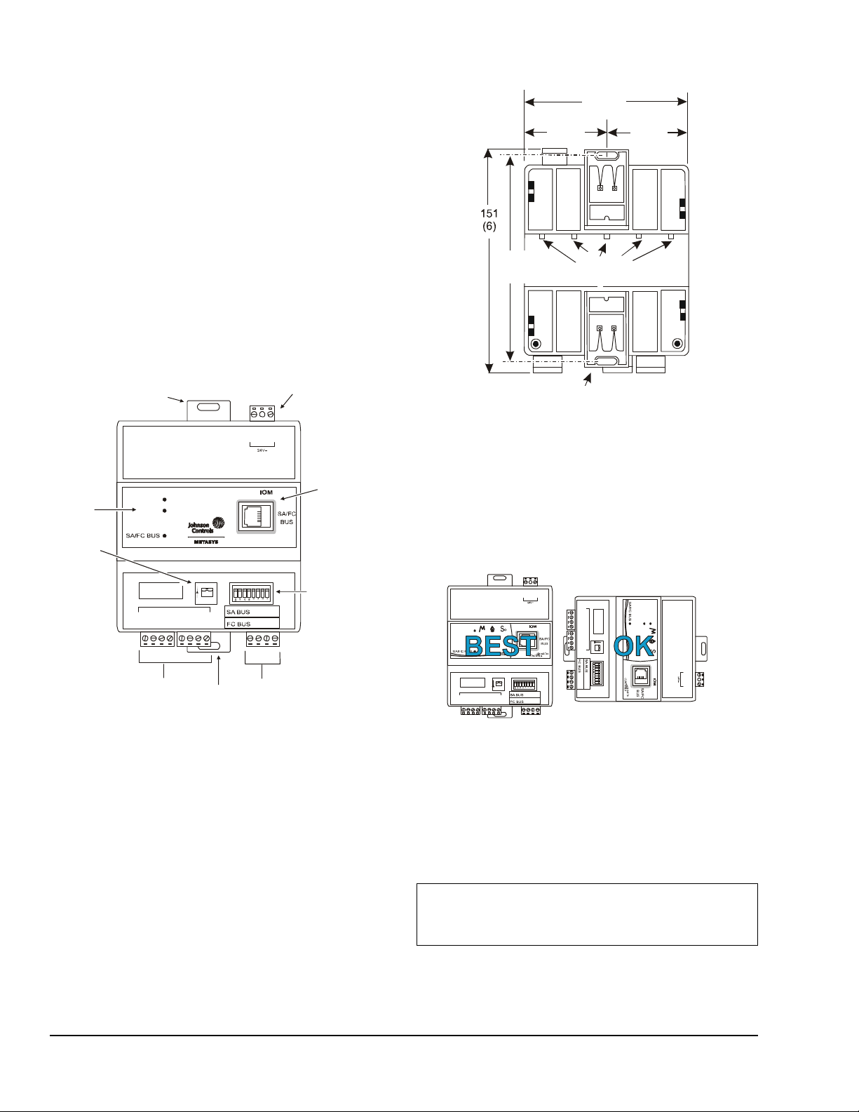
Figure 1: IOM1710 Controller Physical Features
and Wiring Terminal Blocks
FAULT
POWER
A
ON
IN 1
ICOM 1
IN 2
ICOM 2
IN 3
ICOM 3
IN 4
ICOM 4
BINARY INPUTS
COM
+
–
SHLD
+
–
COM
PWR
A
O
N
Binary
Inputs
Clip
EOL
Switch
DIP Switches
SA BUS
FC BUS
Mounting
Clip
Status
LEDs
Port
FIG:IOM17 10_frnt
54
(2.13 )
54
(2.13)
108
(4-1/4 )
F
I
G
:
I
O
M
1
7
1
0
_
b
c
k
Hooks
Mounting Clip
(Shown Extended )
143
(5 - 5/8)
Figure 2: IOM1710 Controller Mounting Features,
mm (in.)
IN 1
ICOM 1
IN 2
ICOM 2
IN 3
ICOM 3
IN 4
ICOM 4
B
I
N
A
R
Y
I
N
P
U
T
S
COM
+
–
SHLD
–
R
ET SY
FAULT
POWER
ADDRESS
ON
I
N
1
I
C
O
M
1
I
N
2
I
C
O
M
2
I
N
3
I
C
O
M
3
I
N
4
I
C
O
M
4
BINARY INPUTS
C
O
M
+
–
S
H
L
D
+
–
C
O
M
P
W
R
ADDRESS Ø = ALL OFF
EOL
O
N
Figure 3: Required Orientation for Wall Mount
Applications
are prone to vibration, such as duct work, or in
areas where electromagnetic emissions from other
devices or wiring can interfere with IOM controller
communication.
• Allow sufficient space for cable and wire
connections (minimum of 51 mm [2 in.] in each
direction).
On panel or enclosure mount applications, observe
these guidelines:
• Do not install the IOM controller in an airtight
enclosure.
• Mount the IOM controller so that the enclosure wall
or the transformer does not obstruct ventilation of
or radiate heat into the IOM controller housing.
24 VAC
Power Terminal
HOT
COM
DIN Rail
DDRESS
DDRESS Ø = ALL OFF
EOL
Mounting
Wall Mount Applications
Use the holes in the mounting clips for wall mount
applications.
To mount the IOM controller on a wall or other vertical
surface:
1. Ensure that the bottom mounting clip(s) are pulled
outward and snapped firmly into the extended
position and that the top clip is securely installed
(Figure 2).
IOM1710 Input/Output Module Installation Instructions2
SA/FC Bus
Device Address
2. Mark the location of the wall mount holes using the
dimensions in Figure 2, or hold the IOM controller
up to the wall as a template and mark the locations.
Note: Mount the IOM controller horizontally for
proper airflow.
T
M
O
O
H
C
A
D
D
R
E
S
S
Ø
=
A
L
L
O
F
F
O
N
E
O
L
A
D
O
N
D
R
E
S
S
+
COM
PWR
P
F
O
A
W
U
L
E
T
R
E
T
S
Y
R
COM
HOT
l
l
w
_
t
n
r
o
:
G
I
F
3. Drill holes in the wall at the locations marked in
Step 2 and insert wall anchors (if necessary).
4. Position the IOM controller and insert the screws
through the holes in the mounting clips, and
carefully tighten all the screws.
IMPORTANT: Do not overtighten the mounting
screws. Overtightening the screws may damage the
mounting clips or IOM housing.
Page 3
DIN Rail Mount Applications
Figure 4: Required Orientation for DIN Rail
Mount Applications
R
ET SY
FAULT
POWER
A
ON
I
N
1
I
C
O
M
1
I
N
2
I
C
O
M
2
I
N
3
I
C
O
M
3
I
N
4
I
C
O
M
4
BINARY INPUTS
C
O
M
+
–
S
H
L
D
+
–
C
O
M
P
W
R
A
O
N
F
I
G
:
I
O
M
1
7
1
0
_
o
r
n
t
_
D
I
N
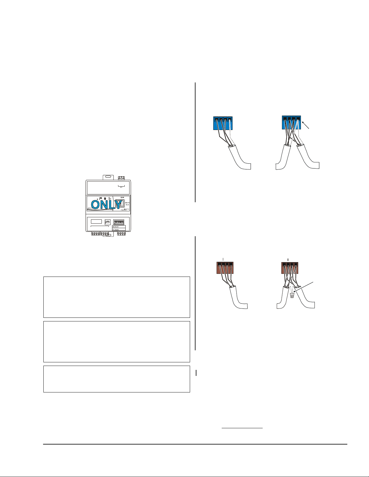
Figure 5: FC Bus Terminal Block Wiring
Isolated Shield
Connection
Terminal
the FC Bus
Segment
FC Bus
Terminal
FIG: fc_bus_term
+
_
COM
SHLD
Terminating Device
on FC Bus Segment
To Next
Device on
the FC Bus
Segment
Daisy Chained Device
on FC Bus Segment
(One twist ed pair is the and leads.
The second pair is COM and SA PWR.)
+ -
Cable Shield
Connection
To Next
Device on
the SA Bus
FIG:sa_bus_terms
SA Bus
Terminal
Block Plugs
Terminating Device
on SA Bus
on SA Bus
To Next
Device on
the SA Bus
+
CO
SA
Figure 6: SA Bus Terminal Block Wiring
To mount the IOM controller on a DIN rail:
1. Securely mount the section of DIN rail horizontally
and centered in the required space.
2. Carefully pull down (outward) the bottom mounting
clip(s) until they lock in place (Figure 2).
Note: The top mounting clip is not used on DIN
rail applications. You may remove the clip.
To wire the IOM controller:
1. Terminate wiring per engineering drawings.
2. If the IOM is connected to the FC Bus of a Network
Automation Engine (NAE) or Network Control
Engine (NCE), wire the FC Bus in a daisy chain
(Figure 5).
s
3. Hang the IOM controller on the DIN rails using the
DIN rail hooks on the back of the IOM controller.
4. Secure the IOM controller on the DIN rail by
pressing the bottom mounting clips up until they
snap into place.
To remove the IOM controller from the DIN rail, snap
the bottom DIN clips to the outboard position and
carefully lift the IOM controller off the DIN rail.
EOL
DDRESS Ø = ALL OFF
Wiring
IMPORTANT: Do not connect 24 VAC supply
power to the IOM controller before finishing wiring
and checking all wiring connections. Short circuits or
improperly connected wires may result in permanent
damage to the equipment.
IMPORTANT: User copper conductors only. Make
all wiring in accordance with local, national, and
regional regulations. The IOM controller is a
low-voltage (<30 VAC) device. Do not exceed the
IOM controller electrical ratings.
to the IOM controller. Static elec tric discharge can
damage the IOM controller and void any warranties.
Refer to the MS/TP Communications Bus Technical
Bulletin (LIT-12011034) for more information on
Master-Slave/Token-Passing (MS/TP) devices.
IMPORTANT: Prevent any static electric discharge
T
M
O
O
H
C
DDRESS
_
+
COM
SHLD
Block Plugs
To Next
Device on
Stranded 3-Wire Tw isted Shiel ded Cable
3. If the IOM is connected to the SA Bus of an NCE or
FEC, wire the SA Bus in a daisy chain (Figure 6).
Daisy Chained Device
M
PWR
+
COM
SA PWR
Stranded, 4- Wire (2 Twisted Pair) Shielded Cable
Note: The SA/FC Bus Port (RJ-12, 6-pin, modular
connector) provides 15 VDC on two of its pins,
which is used to power the MS-BTCVT (Figure 7).
Note: If the IOM controller is at one end of the SA
Bus daisy chain, set the End-of-Line (EOL) switch
to ON.
4. Connect power to the IOM controller.
5. Download and commission the IOM controller . See
the Commissioning
section.
IOM1710 Input/Output Module Installation Instructions 3
Page 4

SA/FC Bus Port
Figure 7: Pin Number Assignments for
Sensor, SA Bus, and FC Bus Ports on
FEC, IOM, and VMA16
(15 VDC)
SA or FC Bus +
SA or FC Bus
-
Power
(15 VDC)
(RJ-12 Mod u l ar Jack)
FIG:RJ_pinout
2
3
4
5
6
1
The SA/FC Bus port on the front of the IOM is an
RJ-12, 6-position modular jack that provide s a
connection for the Wireless Commissioning Converter
(MS-BTCVT).
SA/FC
Bus Port pin assignment is shown in (Figure 7).
See Table 1 for more information. The
Table 1: IOM1710 Controller W iring List
Terminal
Block
Binary IN IN n Dry Contact Maintained Mode
SA/FC Bus
1,2
Port
SA Bus
FC Bus
24~ Power Hot AC Supply Input
Terminal
Function and Electrical Ratings/Requirements Wiring Requirements
Labels
0.01 s minimum pulse width (50 Hz at 50% duty cycle)
Internal 8 V, 1.1k ohm Pullup
Pulse Counter Mode
0.01 s minimum pulse width (50 Hz at 50% duty cycle)
Internal 8 V, 1.1k ohm Pullup
ICOM n The signal common for all Binary IN terminals; isolated from
SA/FC
Bus
1,2
+
COM
1
+
COM
SHLD Provides an optional shield connection.
COM The 24~ Power common; isolated from all other terminal
all other terminal commons
Provides SA Bus communication network.
RJ-12 6-position modular connector
Provides SA Bus communication network. Daisy-chained
Provides FC Bus communication network. Daisy-chained
Supply 20-30 VAC (Nominal 24 VAC)
commons.
Sensor, SA Bus, or FC Bus Port
Bus and Power Com m on
Bus and Power Com m on
Power
(See Table 2 for A, B, or C.)
A
30.5 m (100 ft) maximum length
phone cord
366 m (1,200 ft) maximum
length
0.6 mm to 1.5 mm
24 AWG)
[22 AWG Recommended]
1,524 m (5,000 ft) maximum
length
0.6 mm to 1.5 mm
AWG)
[22 AWG Recommended]
16 AWG
2
(18 to
2
(18 to 24
1. The SA Bus and the SA/FC Bus Port are daisy-chained internally.
2. The SA Bus and FC Bus specifications in this table are for MS/TP bus communications at 38.4k baud. For more
information, refer to the MS/TP Communications Bus Technical Bulletin (LIT-12011034).
IOM1710 Input/Output Module Installation Instructions4
Page 5

Wiring Requirements
137 m 450 f t()
122 m 400 f t()
107 m 350 f t()
91 m 300 ft()
h
t
g
n
76 m 250 ft()
e
L
e
l
61 m 200 ft()
b
a
C
46 m (150 ft )
31 m 100 ft()
15 m 50 ft()
0 m 0 ft()
0.8 mm (20 AWG)
0.6 mm(22 AWG)
N/A (24 AWG )
2
1.5 mm (18 AWG)
Load Current (mA)
Figure 8: Maximum Wire Length by Current and Wire Size
T
able 2: Wire Gauge and Length Guidelines
Guideline Cable Size Maximum Length Assumptions
A
1.5 mm
0.8 mm
0.6 mm
(18 AWG)
(20 AWG)
(22 AWG)
N/A (24 AWG) 106.7 m (350 ft)
B
1.5 mm (18 AWG)
0.8 mm
0.6 mm
N/A
(20 AWG)
(22 AWG)
(24 AWG)
C See Figure 8. See Figure 8. N/A
457.2 m (1,500 ft) 100 mV maximum voltage drop
297.2 m (975 ft)
182.9 m (600 ft)
228.6 m (750 ft) 100 mV maximum voltage drop
137.1 m (450 ft)
91.4 m (300 ft)
61 m (200 ft)
H
T
G
N
L
_
R
I
W
_
G
I
F
450 500400350300250200150100500
Setup and Adjustments
The IOM controller can reside on either the FC Bus or
the SA Bus. When you set the device address, you are
setting the address for the specified bus. The IOM
controller can be connected to only one bus.
Determining the FC Bus or SA Bus Address
The ADDRESS DIP switch sets a unique address for
the controller (or module) on the FC Bus or SA Bus.
Set the address to 4-127 for an IOM. For best
performance, all devices on the same Bus (FC Bus or
SA Bus) should have consecutive addresses. Do not
use Addresses 128 and above when connecting the
IOM to the FC Bus or SA Bus. For more information,
refer to the MS/TP Communications Bus Technical
Bulletin (LIT-12011034).
Table 3 sh
ows the valid FC Bus and SA Bus device
addresses for FECs and IOMs on Johnson Controls®
MS/TP communications bus applications.
Table 3: FC Bus Device Address Descriptions
Device
Description
Address
0 Reserved for FC Bus supervisory controller.
1-3 Reserved for peripheral devices.
4-127 Available for FECs on the FC bus and IOMs
on the SA or FC Bus.
128 Disables (Off) or Enables (ON) a controller for
wireless operation.
129-255 Are not valid addresses for FEC or IOM
controllers on the SA or FC Bus.
IOM1710 Input/Output Module Installation Instructions 5
Page 6

Setting the FC Bus or SA Bus Address
Figure 9: Device Address Switches Set to 21
ON
Note:
Switch 12 8 i s
used to enable or
disable an FEC for
wireless oper ation.
Figure 10: EOL Switch Positions
FIG:E
O
N
For most devices on an FC Bus or SA Bus, the
(non-supervisory) device address is set using the DIP
switches on the device’s ADDRESS DIP switch block.
The DIP switch blocks are binary switch blocks and
each switch represents a binary numerical value when
the switch is set to the ON position. For example,
positioning switches 16, 4, and 1 to ON, as shown in
Figure 9, sets the device address to 21.
FC Bus or SA Bus EOL Switch
The EOL switch applies power termination to the
device’s FC Bus or SA Bus. If the IOM is at the
End-of-Line (EOL) position on the Bus, set the EOL
switch to the ON position. Otherwise, set the EOL
switch to the OFF position (Figure 10). The controller
ships with the EOL switch set in the OFF position.
O
N
OL_Swtch
EOL ON Position EOL Off Position
128
64
32
16
8
1
2
4
FIG:fec_dip_swtch
Commissioning
Commission the IOM controller through the Wireless
Commissioning Converter with Bluetooth® Technology
(MS-BTCVT) and the Controller Configuration Tool
(CCT) software. Refer to the CCT Help.
T roubleshooting
Use Table 4 to troubleshoot the IOM controller.
Table 4: Status Light-Emitting Diodes (LEDs)
Name Color Normal Descriptions
Power Green On Steady Off S teady = No Power
On Steady = Power is supplied by primary voltage.
Fault Red Off Steady Blink - 2 Hz = Download or startup in progress, not ready for normal operation
Off Steady = No faults
On Steady = Device fault or no application loaded
SA/FC Bus Green Blink - 2 Hz Blink - 2 Hz = Data transmission (normal communication)
Off Steady = No data transmission (auto baud in progress)
On Steady = Communication lost, waiting to join communication ring
Repair Information
If the IOM controller fails to operate within its
specifications, replace the unit. For a replacement IOM
controller, contact the nearest Johnson Controls®
representative.
Accessories
Use T able 5 to order accessories fo r the IOM controller .
Table 5: FEC and IOM Accessories (Order Separately) (Part 1 of 2)
Product Code
Description
Number
Y64T15-0 Transformer, 120/208/240 VAC Primary to 24 VAC Secondary, 92 VA, Foot Mount, 30 in. Primary
Leads and 30 in. Secondary Leads, Class 2
Y65A13-0 Transformer, 120 VAC Primary to 24 VAC Secondary, 40 VA, Foot Mount (Y65AS), 8 in. Primary
Leads and 30 in. Secondary Leads, Class 2
Y65T42-0 Transformer , 120/208/240 VAC Primary to 24 VAC Secondary, 40 VA, Hub Mount (Y65SP+), 8 in.
Y65T31-0 Transformer , 120/208/240 VAC Primary to 24 VAC Secondary , 40 VA, Foot Mount (Y65AR+), 8 in.
AP-TBK1002-0 2-position Screw Terminal that Plugs onto VMA output point Spade Lugs
AP-TBK1003-0 3-position Screw Terminal that Plugs onto VMA output point Spade Lugs
IOM1710 Input/Output Module Installation Instructions6
Primary Leads and Secondary Screw Terminals, Class 2
Primary Leads and Secondary Screw Terminals, Class 2
Page 7

Table 5: FEC and IOM Accessories (Order Separately) (Part 2 of 2)
Product Code
Description
Number
AP-TBK4SA-0 Replacement MS/TP SA Bus Terminal, 4 Position Connector, Brown, Bulk Pack
AP-TBK4FC-0 Replacement MS/TP FC Bus Terminal, 4 Position Connector, Blue, Bulk Pack
AP-TBK3PW-0 Replacement Power Terminal, 3 Position Connector, Gray, Bulk Pack
MS-BTCVT-1 Wireless Commissioning Converter, with Bluetooth technology
MS-BTCVTCBL-700 Cable replacement Set for the MS-BTCVT-1 or the NS-ATV7 003-0; includes one 5-foot
retractable cable.
MS-DIS1710-0 Local Controller Display for FEC1610 and FEC2610 models
Technical Specifications
IOM1710 Input/Output Module
Product Code Number MS-IOM1710-0
Supply Voltage 20-30 VAC at 50 or 60 Hz, Class 2 or Safety Extra-Low Voltage (SELV)
Power Consumption 10 VA typical, 14 VA maximum plus all BO and Configurable Output loads
Ambient Conditions Operating: 0 to 50°C (32 to 122°F); 10 to 90% RH noncondensing
Storage: -40 to 70°C (-40 to 158°F); 10 to 90% RH noncondensing
Terminations Screw terminals, 3-Position Screw Terminal Pluggable Blocks, 4-Position Screw Terminal
Pluggable Blocks
Controller Addressing DIP switch set (4-127). Addresses 1-3, 128-255 are reserved.
Communications Bus BACnet® MS/TP; 3-wire FC Bus between the NAE/NCE and other devices. 4-wire SA Bus
when used as expansion to FEC.
Analog Input/Analog Output
Resolution and Accuracy
Mounting On flat surface with screws on three mounting clips or a single 35 mm DIN rail
Dimensions
(Height x Width x Depth)
Housing Plastic housing
Weight 0.31 kg (0.7 lb)
Compliance United States: UL Listed, File E107041, CCN PAZX, UL 916, Energy Management
Analog Input: 16-bit resolution
Analog Output: 16-bit resolution and ±200 mV in 0-10 VDC applications
108 x 127 x 58 mm (4-1/4 x 5 x 2-1/4 in.)
Plastic material: ABS + polycarbonate UL94 5VB
Protection: IP20 (IEC529)
Equipment; UL Listed, File S4977, UUKL 864 - 9th Edition, Smok e Control Equipment (MSIOMx710-0U and MS-IOU4710-0U models only)
FCC Compliant to CFR47, Part 15, Subpart B, Class A
Canada: UL Listed, File E107041, CCN PAZX7, CAN/CSA C22.2 No. 205, Signal
Equipment; Industry Canada Compliant, ICES-003
Europe: CE Mark, EMC Directive 89/336/EEC, in accordance with EN 61000-6-3 (2001)
Generic Emission Standard for Residential and Light Industry and EN 61000-6-2 (2001)
Generic Immunity Standard for Heavy Industrial Environment and the Low Voltage Directive
73/23/EEC in accordance with EN 60730-1 (1999) Automatic electrical controls for
household and similar use.
Australia and New Zealand: C-Tick Mark, Australia/NZ Emissions Compliant
BACnet International: BACnet Testing Laboratories™ (BTL) 135-2004 Listed BACnet
Application Specific Controller (B-ASC)
1
1. For more information, refer to the MS/TP Communications Bus Technical Bulletin (LIT-12011034).
The performance specifications are nominal and conform to acceptable industry standard. For application at conditions beyond these
specifications, consult the local Johnson Controls office. Johnson Controls, Inc. shall not be liable for damages resulting from misapplication or
misuse of its products.
IOM1710 Input/Output Module Installation Instructions 7
Page 8

IOM1710 Input/Output Module Installation Instructions8
Metasys® and Johnson Controls® are registered trademarks of Johnson Controls, Inc.
All other marks herein are the marks of their respective owners. © 2010 Johnson Controls, Inc.
Building Efficiency
507 E. Michigan Street, Milwaukee, WI 53202
Published in U.S.A. www.johnsoncontrols.com
 Loading...