

Page 1

IOM2723 Input/Output Module Installation
Application
The MS-IOM2723 input/output expansion module
is part of the Metasys® system Field Equipment
Controller family. Input/Output expansion modules
(IOMs) expand the number of Input/Output points
connected to either a Network Automation Engine
(NAE), Network Control Engine (NCE), Advanced
Application Field Equipment Controller (FAC), Field
Equipment Controller (FEC), or Variable Air Volume
Modular Assembly (VMA) to monitor and control a
wide variety of HVAC equipment.
Note: The IOM2723 model is only available
in certain regions. Contact your local Johnson
Controls representative for more information.
IOMs operate on an RS-485 BACnet® MS/TP Bus
and integrate into Johnson Controls® and thirdparty BACnet systems. IOMs communicate using the
BACnet MS/TP protocol when directly connected to
the FC Bus.
Note: With Release 10.1 or later of the
Controller Configuration Tool (CCT), VMAs, FECs,
and FACs can be configured to communicate
using either the BACnet MS/TP or the N2 field
bus networking protocol. The operation of
the IOM is not affected by the selection of the
BACnet MS/TP or the N2 protocol in the host
controller, when the IOM is connected to the
host controller using the SA bus.
Guide
Part No. 24-10143-1108 Rev. E
2019-10-18
users will be required to correct the interference at
their own expense.
Canada
This Class (A) digital apparatus meets all the
requirements of the Canadian Interference-Causing
Equipment Regulations.
Cet appareil numérique de la Classe (A) respecte
toutes les exigences du Règlement sur le matériel
brouilleur du Canada.
Installation
Observe these guidelines when installing an
expansion module:
• To minimize vibration and shock damage,
transport the expansion module in the original
container.
• Verify that all parts shipped with the expansion
module.
• Do not drop the expansion module or subject it to
physical shock.
Parts included
• One MS-IOM expansion module with removable
terminal blocks (Power and SA/FC bus are
removable)
North American emissions compliance
United States
This equipment has been tested and found to
comply with the limits for a Class A digital device
pursuant to Part 15 of the FCC Rules. These limits
are designed to provide reasonable protection
against harmful interference when this equipment
is operated in a commercial environment. This
equipment generates, uses, and can radiate radio
frequency energy and, if not installed and used in
accordance with the instruction manual, may cause
harmful interference to radio communications.
Operation of this equipment in a residential area
may cause harmful interference, in which case the
• One installation instructions sheet
Materials and special tools needed
• Three fasteners appropriate for the mounting
surface (M4 screws or #8 screws)
• One 20 cm (8 in.) or longer piece of 35 mm DIN
rail and appropriate hardware for DIN rail mount
• Small straight-blade screwdriver for securing
wires in the terminal blocks
Physical features
The following figure displays the physical features
of the IOM, and the accompanying table provides a
*24101431108E*
(barcode for factory use only)
MS-IOM2723
Page 2
description of the physical features and a reference
to further information where required.
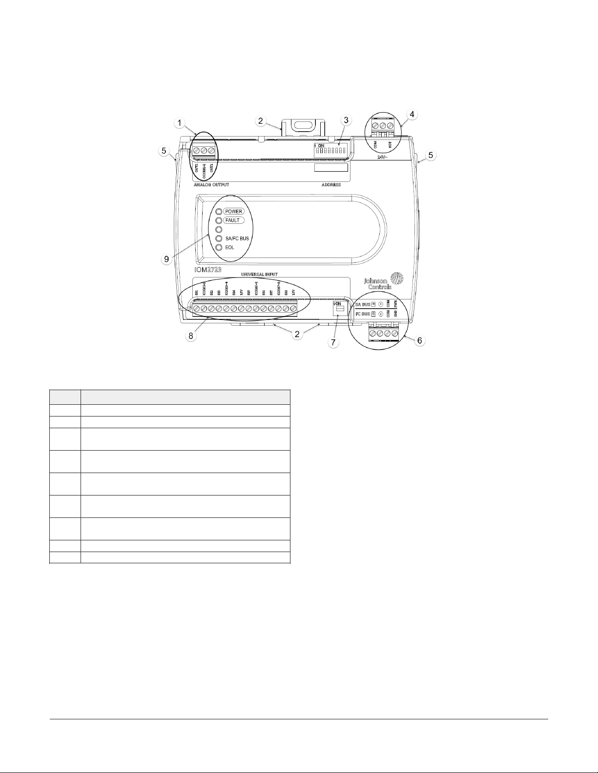
Figure 1: IOM2723 Physical Features
Table 1: IOM2723 physical features callouts and
descriptions
Physical feature: description and references
1 Analog Outputs (AOs) Terminal Block (see Table 2)
2 Mounting Clip
3
4
5
6
7
8 Universal Inputs (UIs) Terminal Block (see Table 2)
9 LED Status Indicators (see Table 8)
Device Address DIP Switch Block (see Setting the device
address)
24 VAC, Class 2 Supply Power Terminal Block (see Supply
power terminal block)
Cover Lift Tab (see Removing the expansion module
cover)
Sensor Actuator (SA) Bus/Field Controller (FC) Bus
Terminal Block (see SA/FC bus terminal block)
End-of-Line (EOL) Termination Switch (see Setting the
End-of-Line (EOL) Switch)
Mounting
Observe the following guidelines when mounting an
expansion module:
• Ensure the mounting surface can support the
expansion module, DIN rail, and any usersupplied enclosure.
• Mount the expansion module horizontally on 35
mm DIN rail whenever possible.
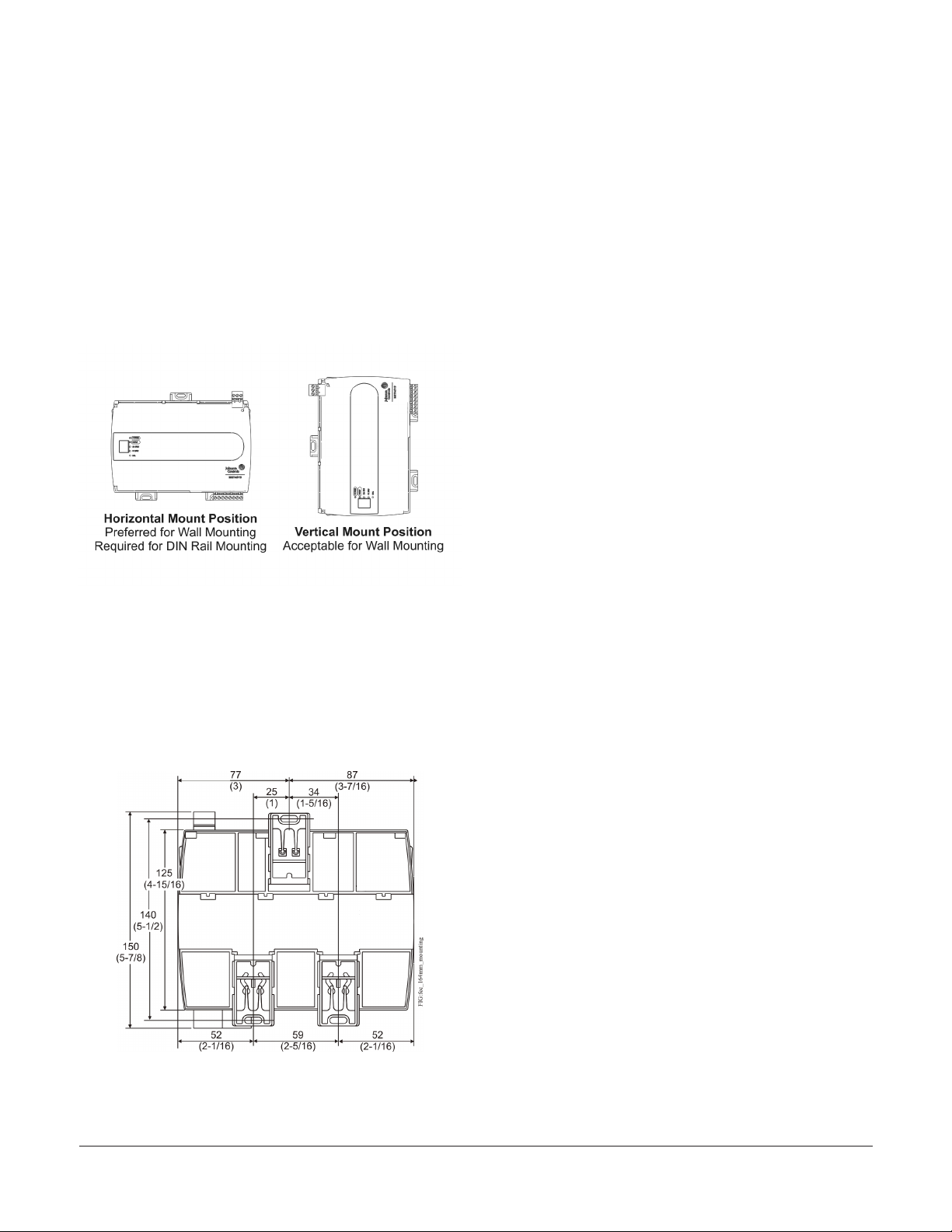
• Mount the expansion module in the proper
mounting position (Figure 2).
• Mount the expansion module on a hard, even
surface whenever possible in wall-mount
applications.
• Use shims or washers to mount the expansion
module securely and evenly on the mounting
surface.
• Mount the expansion module in an area free
of corrosive vapors and observe the Ambient
Conditions requirements in Table 10.
• Provide for sufficient space around the expansion
module for cable and wire connections for easy
cover removal and good ventilation through
the expansion module (50 mm [2 in.] minimum
on the top, bottom, and front of the expansion
module).
• Do not mount the expansion module on surfaces
prone to vibration, such as duct work.
• Do not mount the expansion module in areas
where electromagnetic emissions from other
devices or wiring can interfere with expansion
module communication.
IOM2723 Input/Output Module Installation Guide2
Page 3
Observe these additional guidelines when mounting
an expansion module in a panel or enclosure:
• Mount the expansion module so that the
enclosure walls do not obstruct cover removal or
ventilation through the expansion module.
• Mount the expansion module so that the power
transformer and other devices do not radiate
excessive heat to the expansion module.
• Do not install the expansion module in an airtight
enclosure.
Figure 2: Mounting positions
DIN rail mount applications
Mounting the expansion module horizontally on 35
mm DIN rail is the preferred method.
To mount an expansion module on a 35 mm DIN
rail, complete the following steps:
1. Securely mount a 20 cm (8 in.) or longer section
of 35 mm DIN rail, horizontally and centered
in the desired space, so that the expansion
module mounts in the position shown in Figure
2.
2. Pull the two bottom mounting clips outward
from the expansion module to the extended
position (Figure 3).
3. Hang the expansion module on the DIN rail
by the hooks at the top of the DIN rail channel
on the back of the expansion module (Figure
3), and position the expansion module snugly
against the DIN rail.
4. Push the bottom mounting clips inward (up) to
secure the expansion module on the DIN rail.
Mounting features and dimensions
See the following figure for mounting dimensions
listed in millimeters and inches. Inches are listed
in parenthesis. The following figure also illustrates
the DIN rail channel and the mounting clips in an
extended position.
Figure 3: Back of expansion module
To remove the expansion module from the DIN rail,
pull the bottom mounting clips out to the extended
position and carefully lift the expansion module off
the DIN rail.
Wall mount applications
To mount an expansion module directly on a wall
or other flat vertical surface, complete the following
steps:
1. Pull the two bottom mounting clips outward
and ensure they are locked in the extended
position, as shown in Figure 3.
2. Mark the mounting hole locations on the wall
using the dimensions in Figure 3 and one of
the mount positions shown in Figure 2. You can
also hold the expansion module up to the wall
or surface in a proper mount position and mark
the hole locations through the mounting clips.
3. Drill holes in the wall or surface at the marked
locations, and insert appropriate wall anchors
in the holes (if necessary).
IOM2723 Input/Output Module Installation Guide 3
Page 4
4. Hold the expansion module in place, and insert
the screws through the mounting clips and into
the holes (or anchors). Carefully tighten all of
the screws.
Important: Do not overtighten the mounting
screws. Overtightening the screws may
damage the mounting clips.
Wiring
Warning
Risk of Electric Shock:
Disconnect or isolate all power supplies before making electrical connections. More than one disconnection or isolation may be required to completely de-energize equipment. Contact with components carrying
hazardous voltage can cause electric shock and may
result in severe personal injury or death.
Avertissement
ATTENTION
Mise En Garde: Risque de dégâts matériels:
Ne pas mettre le système sous tension avant d'avoir
vérifié tous les raccords de câblage. Des fils formant un court-circuit ou connectés de façon incorrecte risquent d'endommager irrémédiablement
l'équipement.
Important: Do not exceed the expansion
module electrical ratings. Exceeding expansion
module electrical ratings can result in
permanent damage to the expansion modules
and void any warranty.
Important: Use copper conductors only. Make
all wiring in accordance with local, national, and
regional regulations.
Important: Electrostatic discharge can damage
expansion module components. Use proper
electrostatic discharge precautions during
installation, setup, and servicing to avoid
damaging the expansion module.
Risque de décharge électrique:
Débrancher ou isoler toute alimentation avant de
réaliser un branchement électrique. Plusieurs isolations et débranchements sont peut-être nécessaires pour -couper entièrement l'alimentation de
l'équipement. Tout contact avec des composants conducteurs de tensions dangereuses risque d'entraîner
une décharge électrique et de provoquer des
blessures graves, voire mortelles.
CAUTION
Risk of Property Damage:
Do not apply power to the system before checking all
wiring connections. Short circuited or improperly connected wires may result in permanent damage to the
equipment.
For detailed information on configuring and wiring
an MS/TP bus, FC bus, and SA bus, refer to the MS/TP
Communications Bus Technical Bulletin (LIT-12011034).
Terminal blocks and bus ports
See Figure 1 for terminal block and bus port
locations on the expansion module. Observe the
following guidelines when wiring an expansion
module.
Input and output terminal blocks
The input terminal blocks are mounted on
the bottom of the expansion module and the
output terminal blocks are mounted on the
top of the expansion module. See Table 2 for
more information about I/O terminal functions,
requirements, and ratings.
SA/FC bus terminal block
An IOM can be connected to a Sensor/Actuator
(SA) bus or a Field Controller (FC) bus, but not to
both buses simultaneously. The SA/FC bus terminal
block is a removable, 4-terminal plug that fits into a
board-mounted jack.
When connecting the IOM to an FC bus, wire the
bus terminal block plugs on the expansion module,
and the other controllers and expansion modules
IOM2723 Input/Output Module Installation Guide4
Page 5
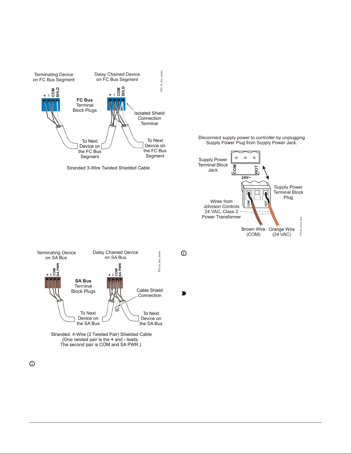
in a daisy-chain configuration using 3-wire twisted,
shielded cable as shown in Figure 4.
Figure 4: FC bus terminal block wiring
When connecting the IOM to an SA bus, wire the bus
terminal block plugs on the expansion module and
other SA bus devices in a daisy-chain configuration
using 4-wire twisted, shielded cable as shown in
Figure 5.
Supply power terminal block
The 24 VAC supply power terminal block is a gray,
removable, 3-terminal plug that fits into a boardmounted jack on the top right of the expansion
module.
Wire the 24 VAC supply power wires from the
transformer to the HOT and COM terminals on the
terminal plug as shown in Figure 6. The middle
terminal on the supply power terminal block is not
used.
Figure 6: 24 VAC supply power terminal block
wiring
Figure 5: SA bus terminal block wiring
Note: The SA PWR/SHLD terminal does not
supply 15 VDC. The SA PWR/SHLD terminal
is isolated and can be used to connect (daisy
chain) the 15 VDC power leads on the SA bus
(Figure 5) or the cable shields on the FC bus
(Figure 4). The SA bus supervisor supplies 15
VDC to devices on the SA bus requiring power.
Note: The supply power wire colors may
be different on transformers from other
manufacturers. Refer to the transformer
manufacturer’s instructions and the project
installation drawings for wiring details.
Important: Connect 24 VAC supply power to
the expansion module and all other network
devices so that transformer phasing is uniform
across the network devices. Powering network
devices with uniform 24 VAC supply power
phasing reduces noise, interference, and
ground loop problems. The expansion module
does not require an earth ground connection.
IOM2723 Input/Output Module Installation Guide 5
Page 6

Terminal Wiring Guidelines, Functions, Ratings, and Requirements
Input and output wiring guidelines
Table 2 provides information and guidelines about
the functions, ratings, and requirements for the
expansion module input and output terminals, and
references guidelines for determining proper wire
sizes and cable lengths.
In addition to the wiring guidelines in Table 2,
observe the following guidelines when wiring
expansion module inputs and outputs:
• Run all low-voltage wiring and cables separate
from high-voltage wiring.
• All input and output cables, regardless of wire
size or number of wires, should consist of
stranded, insulated, and twisted copper wires.
• Shielded cable is not required for input or output
cables.
• Shielded cable is recommended for input
and output cables that are exposed to high
electromagnetic or radio frequency noise.
• Inputs/outputs with cables less than 30 m (100 ft)
typically do not require an offset in the software
setup. Cable-runs over 30 m (100 ft) may require
an offset in the input/output software setup.
IOM2723 Input/Output Module Installation Guide6
Page 7

I/O Terminal blocks, ratings, and requirements
Table 2: I/O terminal blocks, functions, ratings, requirements, and cables
Terminal block label
UNIVERSAL
(Inputs)
ANALOG
(Outputs)
Terminal
label
+15 V
INn
ICOMn Universal Input Common for all Universal Input terminals Same as (Universal) INn
OUTn
OCOMn Analog Output Signal Common for all Analog OUT terminals.
Function, ratings, requirements
15 VDC Power Source for active (3-wire) input devices
connected to the Universal INn terminals.
Provides 100 mA total current
Analog Input - Voltage Mode (0–10 VDC)
10 VDC maximum input voltage
Internal 75k ohm Pull-down
Analog Input - Current Mode (4–20 mA)
Internal 100 ohm load impedance
Note: A current loop fail-safe jumper can be positioned
to maintain a closed 4 to 20 mA current loop, even when
the power to the expansion module is interrupted or off.
Analog Input - Resistive Mode (0–600k ohm)
Internal 12 V. 15k ohm pull up
Qualified Sensors: 0-2k ohm potentiometer, RTD (1k Nickel
[ Johnson Controls sensor], 1k Platinum, and A99B Silicon
Temperature Sensor) Negative Temperature Coefficient (NTC)
Sensor (10k Type L, 10k JCI Type II, 2.252k Type II)
Binary Input - Dry Contact Maintained Mode
1 second minimum pulse width
Internal 12 V. 15k ohm pull up
Analog Output - Voltage Mode (0–10 VDC)
10 VDC maximum output voltage
10 mA maximum output current
Required an external load of 1,000 ohm or more.
Note: The Analog Output (AO) operates in the Voltage
Mode when connected to devices with impedances
greater than 1,000 ohm. Devices that drop below 1,000
ohm may not operate as intended for Voltage Mode
applications.
Analog Output - Current Mode (4–20 mA)
Requires an external load between 0 and 300 ohm.
Note: The Analog Output (AO) operates in the Current
Mode when connected to devices with impedances less
than 300 ohm. Devices that exceed 300 ohm may not
operate as intended for Current Mode applications.
Determine wire size and
maximum cable length
Same as (Universal) INn
Note: Use 3-wire cable for
devices that source power
from the +15 V terminal.
See Guideline A in Table 3.
See Guideline B in Table 3.
See Guideline A in Table 3.
See Guideline A in Table 3.
See Guideline C in Table 3.
IOM2723 Input/Output Module Installation Guide 7
Page 8

Cable and wire length guidelines
The following table defines cable length guidelines
for the various wire sizes that may be used for
wiring low-voltage (<30 V) input and outputs.
Table 3: Cable length guidelines
Guideline Wire size/gauge and type
1.0 mm (18 AWG) stranded copper 457 m (1,500 ft) twisted wire
0.8 mm (20 AWG) stranded copper 297 m (975 ft) twisted wire
A
B
C
0.6 mm (22 AWG) stranded copper 183 m (600 ft) twisted wire
0.5 mm (24 AWG) stranded copper 107 m (350 ft) twisted wire
1.0 mm (18 AWG) stranded copper 229 m (750 ft) twisted wire
0.8 mm (20 AWG) stranded copper 137 m (450 ft) twisted wire
0.6 mm (22 AWG) stranded copper 91 m (300 ft) twisted wire
0.5 mm (24 AWG) stranded copper 61 m (200 ft) twisted wire
See Figure 7 to select wire size/gauge.
Use stranded copper wire.
Maximum cable length
and type
See Figure 7 to determine
cable length. Use twisted
wire cable.
Assumptions
100 mV maximum voltage drop
Depending on cable and the connected input or
output device, you may have to define an offset
in the setup software for the input or output
point.
100 mV maximum voltage drop
Depending on cable and the connected input or
output device, you may have to define an offset
in the setup software for the input or output
point.
N/A
Maximum cable length versus load current
Use the following figure to estimate the maximum
cable length relative to the wire size and the load
current (in mA) when wiring inputs and outputs.
Note: The following information applies to lowvoltage (<30 V) inputs and outputs only.
Figure 7: Maximum wire length for low-voltage
(<30 V) Inputs and Outputs by current and wire
size
Communications bus and supply power wiring guidelines
Table 4 provides information about the functions,
ratings, and requirements for the communication
bus and supply power terminals; it additionally
provides guidelines for wire sizes, cable types, and
cable lengths when wiring the expansion module's
communication buses and supply power.
In addition to the guidelines in Table 4, observe
these guidelines when wiring an SA or FC bus and
the 24 VAC supply power:
• Run all low-voltage wiring and cables separate
from high-voltage wiring.
• All SA and FC bus cables, regardless of wire size,
should be twisted, insulated, stranded copper
wire.
• Shielded cable is strongly recommended for all SA
and FC bus cables.
• Refer to the MS/TP Communications Bus
Technical Bulletin (LIT-12011034) for detailed
information regarding wire size and cable length
requirements for the SA and FC buses.
IOM2723 Input/Output Module Installation Guide8
Page 9

Communications bus and supply power terminal blocks, ratings, and requirements
Table 4: Communications bus and supply power terminal blocks, functions, ratings, requirements, and
cables
Terminal block/Port
label
FC BUS
or
SA BUS
24~
Note: The SA Bus and FC Bus wiring recommendations in this table are for MS/TP bus at 38,400 baud.
For more information, refer to the MS/TP Communications Bus Technical Bulletin (LIT-12011034).
Terminal labels Function, electrical ratings/Requirements required cable type
+
-
COM
SHLD
or
SA PWR
HOT
COM 24 VAC Power Supply - Common
FC or SA Bus Communications
Signal Reference (Common) for FC or SA Bus
communications
SHLD on FC Bus: Isolated terminal (optional
shield drain connection)
SA PWR on SA Bus: 15 VDC power lead
connection.
Note: The SA PWR terminal on an IOM
expansion module does not supply 15
VDC. The SA bus supervisor supplies 15
VDC to devices on the SA bus requiring
power.
24 VAC Power Supply - Hot
Supplies 20–30 VAC (Nominal 24 VAC)
FC Bus: 0.6 mm (22 AWG) stranded, 3-wire
twisted, shielded cable required.
SA Bus: 0.6 mm (22 AWG) stranded, 4-wire
(2 twisted-pairs), shielded cable required.
Note: On the SA Bus, the + and - wire
are one twisted pair, and the COM
and SA PWR are the second twisted
pair of wires.
0.8 mm to 1.0 mm
(18 AWG) 2-wire
IOM2723 Input/Output Module Installation Guide 9
Page 10

Termination details
A set of Johnson Controls termination diagrams
provides details for wiring inputs and outputs to the
Table 5: Termination details
Type of field device
Temperature Sensor UI
Type of Input/
Output
Termination diagrams
controllers. See the figures in this section for the
applicable termination diagrams.
Voltage Input - External
Source
Voltage Input - Internal
Source
Voltage Input (SelfPowered)
UI
UI
UI
Current Input - External
Source (Isolated)
Current Input - Internal
Source (2-wire)
IOM2723 Input/Output Module Installation Guide10
UI
UI
Page 11

Table 5: Termination details
Type of field device
Type of Input/
Output
Termination diagrams
Current Input - Internal
Source (3-wire)
Current Input - External
Source (in Loop)
Feedback from
EPP-1000
Dry Contact (Binary
Input)
UI
UI
UI
UI
0–10 VDC Output to
Actuator (External
Source)
0–10 VDC Output to
Actuator (Internal
Source)
AO
AO
IOM2723 Input/Output Module Installation Guide 11
Page 12

Table 5: Termination details
Type of field device
Type of Input/
Output
Termination diagrams
Analog Output
(Current)
4–20 mA Output to
Actuator
Voltage (Analog Output) AO
AO
AO
4–20 mA Output to
Actuator
AO
Setup and Adjustments
Setting the device address
Metasys expansion modules are master devices on
MS/TP (SA or FC) buses. Before operating expansion
modules on a bus, you must set a valid and unique
device address for each expansion module on
the bus. You set an expansion module's device
address by setting the positions of the switches on
the DIP switch block at the top of the expansion
module. Device addresses 4 through 127 are the
valid addresses for these expansion modules.
The following table describes the FC bus and SA
bus device addresses for Johnson Controls MS/TP
communications bus applications:
Table 6: SA/FC bus device address descriptions
Device
address
0
(Switch
128 Off)
Use on description
Reserved for FC Bus Supervisory
Controller (not for use on controllers or
expansion modules).
Reserved for peripheral devices (not
1 to 3
(Switch
128 Off)
for use on controllers or expansion
modules).Reserved for FC Bus
Supervisory Controller (not for use on
expansion modules).
IOM2723 Input/Output Module Installation Guide12
Page 13

Table 6: SA/FC bus device address descriptions
Device
address
4 to 127
(Switch
128 Off)
The DIP switch block has eight switches numbered
128, 64, 32, 16, 8, 4, 2, and 1. Switches 64 through 1
are device address switches. Switch 128 must be set
to off for all hard-wired SA and FC bus applications.
Figure 8: Device address DIP switch block set to
address 21
Use on description
Used for MS/TP master devices
(controllers or expansion modules) that
are hardwired to an SA Bus or FC Bus.
Note: To do this, set the highest number switch
that is less than or equal to the intended device
address to ON. Then continue setting lower
numbered switches until the total equals the
intended address. For example, if the intended
device address is 21, set switches 16, 4, and 1 to
ON (16+4+1= 21) and all other switches to OFF.
3. Set a unique and sequential device address for
each of the expansion modules connected on
the SA or FC bus starting with device address 4.
Note: To ensure the best bus performance, set
sequential device addresses with no gaps in
the device address range (4, 5, 6, 7, 8, 9, and
so on). The expansion modules do not need
to be physically connected on the bus in their
numerical device address order
4. Write each expansion module's device address
on the white label below the DIP switch block
on the expansion module's cover.
Removing the expansion module
Note: Metasys® field controllers ship with
switch 128 ON and the remaining address
switches off rendering the controllers wired
subordinate devices, which do not operate
on MSTP buses, but do not interfere with
bus operation. Set a valid and unique device
address on the expansion module before
applying power to the expansion module on
the bus.
To set the device addresses on Metasys
expansion modules, complete the following
steps:
1. Set all of the switches on the address DIP
switch block (128 through 1) to OFF.
2. Set one or more of the seven address switches
(64 though 1) to ON, so that the sum of the
switch numbers set to ON equals the intended
device address, and ensure that switch 128
remains set to OFF.
cover
Important: Electrostatic discharge can damage
expansion module components. Use proper
electrostatic discharge precautions during
installation, setup, and servicing to avoid
damaging the expansion module.
Important: Disconnect all power sources to
the expansion module before removing cover
and changing the position of any jumper or the
EOL switch on the expansion module. Failure to
disconnect power before changing a jumper or
EOL switch position can result in damage to the
expansion module and void any warranties.
The expansion module cover is held in place by
four plastic latches that extend from the base
and snap into slots on the inside of the housing
cover.
To remove the expansion module cover,
complete the following steps:
1. Place your fingernails under the two cover
lift tabs (Figure 1) on the sides of the housing
cover and gently pry the top of the cover away
from the base to release the cover from the two
upper latches.
IOM2723 Input/Output Module Installation Guide 13
Page 14

2. Pivot the top of the cover further to release it
from the lower two latches.
3. Replace the cover by placing it squarely over
the base, and then gently and evenly push the
cover on to the latches until they snap into the
latched position.
Figure 9: Controller with cover removed
Note: The EOL termination rules for SA
buses and FC buses are different. Refer to
the MS/TP Communications Bus Technical
Bulletin (LIT-12011034) for detailed information
regarding EOL termination rules and EOL
switch settings on SA and FC buses.
3. If the expansion module is a terminating device
on the FC bus, set the EOL switch to ON. If the
expansion module is not a terminating device
on the bus, set the EOL switch to OFF.
When an expansion module is connected to power
with its EOL switch set to ON, the amber EOL LED on
the expansion module cover is lit.
UI current loop jumpers
The UI current loop fail-safe jumpers are on the
circuit board under the expansion module cover
near the UI terminals. When a UI is defined (in the
system software) as a 4 to 20 mA Analog Input
and the UI’s current loop jumper is in the Disabled
(default) position (Figure 11), the 4 to 20 mA current
loop circuit opens whenever power to the expansion
module is interrupted or off.
Setting the End-of-Line (EOL) switch
Each expansion module has an EOL switch. When
the EOL switch is set to ON, it sets the expansion
module as a terminating device on the bus. See
Figure 10 for the EOL switch location. The default
EOL switch position is OFF.
Figure 10: End-of-Line switch positions
To set the EOL switch on an expansion module,
complete the following steps:
1. Determine the physical location of the
expansion module on the SA or FC bus.
2. Determine if the expansion module must be set
as a terminating device on the bus.
Figure 11: Current loop jumper positions
Setting the current loop jumper to the Enabled
position (Figure 11) connects an internal 100 ohm
resistor across the UI terminals, which maintains the
4 to 20 mA current loop circuit even when power to
the expansion module is interrupted or off.
Important: Current Loop jumpers must be in
the Disabled (default) position for all UIs that
are not set up to operate as 4 to 20 mA analog
inputs.
Table 7: UI Inputs and Jumper Labels
Universal Input Label
IN1 J1
IN2 J2
IN3 J3
Jumper Label on Circuit Board
Label
IOM2723 Input/Output Module Installation Guide14
Page 15

Table 7: UI Inputs and Jumper Labels
Universal Input Label
IN4 J4
IN5 J5
IN6 J6
IN7 J7
IN8 J8
Jumper Label on Circuit Board
Label
Firmware Package File
The MS-FCP-0 equipment controller firmware
package files are required for CCT to configure and
commission the controllers. The firmware package
files also allow you to upgrade an existing controller
to the latest firmware release available for that
controller.
Beginning at CCT Release 13, the firmware package
files are orderable separately; they are not included
Commissioning
with CCT. They are obtained from the Metasys
software licensing portal, and are loaded and
You commission expansion modules with Controller
Configuration Tool (CCT) software, using a
Bluetooth Wireless Commissioning Converter
(BTCVT), through Mobile Access Portal (MAP)
Gateway at version 4.2 or above, or in BACnet router
mode when connected to a Supervisory Controller.
licensed on the computer/server that is running
CCT.
For additional information about the firmware
package files, refer to the CCT Installation Instructions
(LIT-12011259).
Refer to the Controller Tool Help (LIT-12011147) for
detailed information on commissioning expansion
Troubleshooting
modules.
Note: The MAP Gateway serves as a
replacement for the BTCVT, which is no longer
available for purchase, but continues to be
Observe the Status LEDs on the front of the
expansion module. Table 8 provides LED status
indicator information for troubleshooting the
expansion module.
supported.
Table 8: Status LEDs and description of LED states
LED label LED color Normal LED state Description of LED states
Off Steady = No Supply Power or the expansion module’s polyswitch/resettable
POWER Green On Steady
FAULT Red Off Steady
SA/FC BUS Green Blink - 2 Hz
EOL Amber
Off (Except on
terminating devices)
fuse is open. Check Output wiring for short circuits and cycle power to expansion
module.
On Steady = Power Connected
Off Steady = No Faults
On Steady = Device Fault
Blink - 2 Hz = Download or Startup in progress, not ready for normal operation
Blink - 2 Hz = Data Transmission (normal communication)
Off Steady = No Data Transmission (N/A - auto baud not supported)
On Steady = Communication lost, waiting to join communication ring
On Steady = EOL switch in ON position
Off Steady = EOL switch in OFF position
Repair information
If an expansion module fails to operate within its
specifications, replace the expansion module. For
a replacement expansion module, contact your
Johnson Controls representative.
IOM2723 Input/Output Module Installation Guide 15
Page 16

Accessories
See the following table for expansion module
accessories ordering information.
Table 9: Accessories Ordering Information
Product Code Number Description
Refer to the Mobile Access Portal Gateway Catalog Page (LIT-1900869) to identify the
Mobile Access Portal (MAP) Gateway
TL-CCT-0 Metasys Controller Configuration Tool (CCT) Software
MS-FCP-0 Metasys Field Controller Firmware Package Files for CCT
TP-2420 Transformer, 120 VAC Primary to 24 VAC secondary, 20 VA, Wall Plug
Y65T31-0
AS-CBLTSTAT Cable adapter for connection to 8-pin TE-6700 Series sensors
AS-XFR050-0 Power transformer (Class 2, 24 VAC, 50 VA maximum output), no enclosure
AP-TBK4SA-0 Replacement SA Bus Terminal Blocks, 4-Position, Brown, Bulk Pack of 10
AP-TBK4FC-0 Replacement FC Bus Terminal Blocks, 4-Position, Blue, Bulk Pack of 10
AP-TBK3PW-0 Replacement Power Terminal Blocks, 3-Position, Gray, Bulk Pack of 10
appropriate product for your region.
Note: The MAP Gateway serves as a replacement for the BTCVT, which is no longer
available for purchase, but continues to be supported.
Transformer, 120/208/240 VAC Primary to 24 VAC Secondary, 40 VA, Foot Mount, 8 in.
Primary Leads and Secondary Screw Terminals, Class 2
Note: Additional Y6x-x Series transformers are also available. Refer to the Series Y63,
Y64, Y65, Y66, and Y69 Transformers Product Bulletin (LIT-125755) for more information.
IOM2723 Input/Output Module Installation Guide16
Page 17

Technical specifications
Table 10: IOM2723 technical specifications
MS-IOM2723-0 Input/Output Module
Product Code Number
Power Requirement
Power Consumption 14 VA maximum
Ambient Conditions
Addressing
Communications Bus
Processor RX631 Renesas® 32-bit microcontroller
Memory 4 MB external serial flash memory and 768 KB internal flash and 128 KB internal RAM
Input and Output Capabilities
Analog Input and Output Resolution and
Accuracy
Terminations
Mounting
Housing
Dimensions (Height x Width x Depth)
Weight 0.5 kg (1.1 lb)
Compliance
BACnet International Compliance
Note: This model is only available in certain regions. Contact your local Johnson
Controls representative for more information.
24 VAC (nominal, 20 VAC minimum/30 VAC maximum), 50/60 Hz, power supply Class 2
(North America), Safety Extra-Low Voltage (SELV) (Europe)
Operating: 0°C to 50°C (32°F to 122°F); 10% to 90% RH noncondensing
Storage: -40°C to 80°C (-40°F to 176°F); 5% to 95% RH noncondensing
DIP switch set; valid expansion module device addresses 4–127 (Device addresses 0–3 and
128–255 are reserved and not valid expansion module addresses)
BACnet MS/TP, RS-485:
3-wire FC Bus between the supervisory controller and other controllers or expansion
modules (for MS/TP bus communications at 38,400 baud)
4-wire SA Bus between expansion module, network sensors and other sensor/actuator
devices, includes a lead to source 15 VDC supply power (from controller or expansion
modules) to bus devices (for MS/TP bus communications at 38,400 baud)
8 - Universal Inputs: Defined as 0–10 VDC, 4–20 mA, 0–600k ohm, or Binary Dry Contact
2 - Analog Outputs: Defined as 0–10 VDC or 4–20 mA
Input: 15-bit resolution
Output: 15-bit resolution, +/-200 mV accuracy in 0–10 VDC applications
Input/Output: Fixed Screw Terminal Blocks
SA/FC Bus and Supply Power: 4-Wire and 3-Wire Pluggable Screw Terminal Blocks
Horizontal on single 35 mm DIN rail mount (preferred), or screw mount on flat surface
with three integral mounting clips on expansion module
Enclosure material: ABS and polycarbonate UL94 5VB; self-extinguishing, plenum-rated
Protection Class: IP20 (IEC529)
150 mm x 164 mm x 53 mm (5-7/8 in. x 6-1/2 in. x 2-1/8 in.) including terminals and
mounting clips
Note: Mounting space requires an additional 50 mm (2 in.) on top, bottom, and
front face of expansion module for easy cover removal, ventilation, and wire
terminations.
United States: UL Listed, File E107041, CCN PAZX, UL 916, Energy Management
Equipment
FCC Compliant to CFR47, Part 15, Subpart B, Class A
Canada: UL Listed, File E107041, CCN PAZX7 CAN/CSA C22.2 No.205, Signal Equipment
Industry Canada Compliant, ICES-003
Europe: Johnson Controls declares that this product is in compliance with the essential
requirements and other relevant provisions of the EMC Directive.
Australia and New Zealand: RCM Mark, Australia/NZ Emissions Compliant
BACnet International: BACnet Testing Laboratories (BTL) Protocol Revision 15 Listed and
Certified BACnet Smart Actuator (B-SA)
The performance specifications are nominal and
conform to acceptable industry standard. For
application at conditions beyond these specifications,
consult the local Johnson Controls® office. Johnson
IOM2723 Input/Output Module Installation Guide 17
Page 18

Controls shall not be liable for damages resulting from
misapplication or misuse of its products.
Product warranty
This product is covered by a limited
warranty, details of which can be found at
www.johnsoncontrols.com/buildingswarranty.
Single point of contact
APAC Europe NA/SA
JOHNSON CONTROLS
C/O CONTROLS PRODUCT
MANAGEMENT
NO. 32 CHANGJIJANG RD NEW
DISTRICT
WUXI JIANGSU PROVINCE 214028
CHINA
For more contact information, refer to
www.johnsoncontrols.com/locations.
JOHNSON CONTROLS
WESTENDHOF 3
45143 ESSEN
GERMANY
JOHNSON CONTROLS
507 E MICHIGAN ST
MILWAUKEE WI 53202
USA
© 2019 Johnson Controls. All rights reserved. All specifications and other information shown were current as of document revision and
are subject to change without notice.
www.johnsoncontrols.com
 Loading...