

Page 1
Variable Speed Drives Series III
Quick Start Guide
Effective April 2018
New Information
CONTENTS
Step 1—Variable Speed Drives Series III Overview . . . . 1
Step 2—Keypad Operation Overview . . . . . . . . . . . . . . . 3
Step 3—Menu Navigation . . . . . . . . . . . . . . . . . . . . . . . . 6
Step 4—Startup Wizard . . . . . . . . . . . . . . . . . . . . . . . . . . 8
Step 5—Standard Parameter List . . . . . . . . . . . . . . . . . . 10
Appendix A—Fault and Warning Codes . . . . . . . . . . . . . 40
Page 2

Page 3
Step 1—Variable Speed Drives Series III Overview
Step 1—Variable Speed Drives Series III Overview
This chapter describes the purpose and contents of this
manual, the receiving inspection recommendations and
the variable frequency drive catalog numbering system.
How to Use this Manual
The purpose of this manual is to provide you with information
necessary to install, set and customize parameters, start up,
troubleshoot and maintain the
variable frequency drive (VFD).
To provide for safe installation and operation of the
equipment, read the safety guidelines at the beginning of this
manual and follow the procedures outlined in the following
chapters before connecting power to the VFD. Keep this
operating manual handy and distribute to all users,
technicians and maintenance personnel for reference.
Receiving and Inspection
The Variable Speed Drives Series III has met a stringent
series of factory quality requirements before shipment. It is
possible that packaging or equipment damage may have
occurred during shipment. After receiving your VFD, please
check for the following:
Check to make sure that the package includes the Instruction
Leaflet, Quick Start Guide, and accessory packet. The
accessory packet includes:
●
Rubber grommets
●
Control cable grounding clamps
●
Additional grounding screw
Inspect the unit to ensure it was not damaged during
shipment.
Make sure that the part number indicated on the nameplate
corresponds with the catalog number on your order.
If shipping damage has occurred, please contact and file a
claim with the carrier involved immediately.
If the delivery does not correspond to your order, please
contact your sales representative.
Note: Do not destroy the packing. The template printed on
the protective cardboard can be used for marking the
mounting points of the VFD on the wall or in a cabinet.
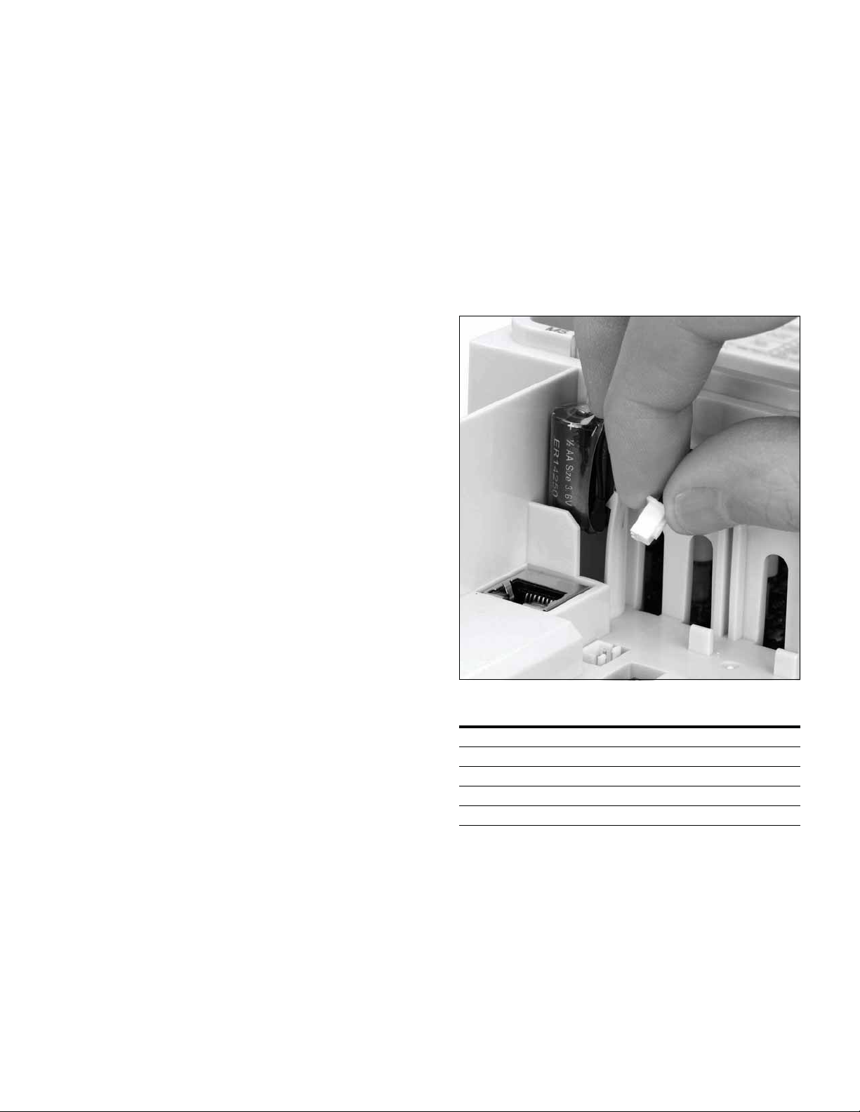
Real Time Clock Battery Activation
To activate the real time clock (RTC) functionality in the
VFD
, the RTC battery (already mounted in the drive) must
be connected to the control board.
Simply remove the primary drive cover, locate the RTC
battery directly below the keypad, and connect the white
2-wire connector to the receptacle on the control board.
Figure 1. RTC Battery Connection
Table 1. Common Abbreviations
Abbreviation Definition
CT Constant torque with high overload rating (150%)
VT Variable torque with low overload rating (110%)
I
H
I
L
VFD Variable Frequency Drive
High Overload (150%)
Low Overload (110%)
Variable Speed Drives Series III LIT-12012996—April 2018 www.johnsoncontrols.com 1
Page 4
Step 1—Variable Speed Drives Series III Overview
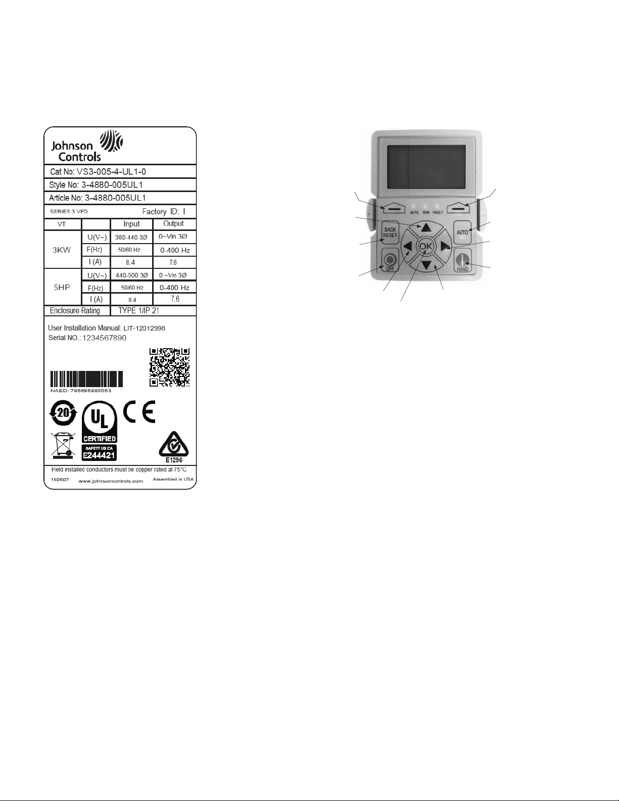
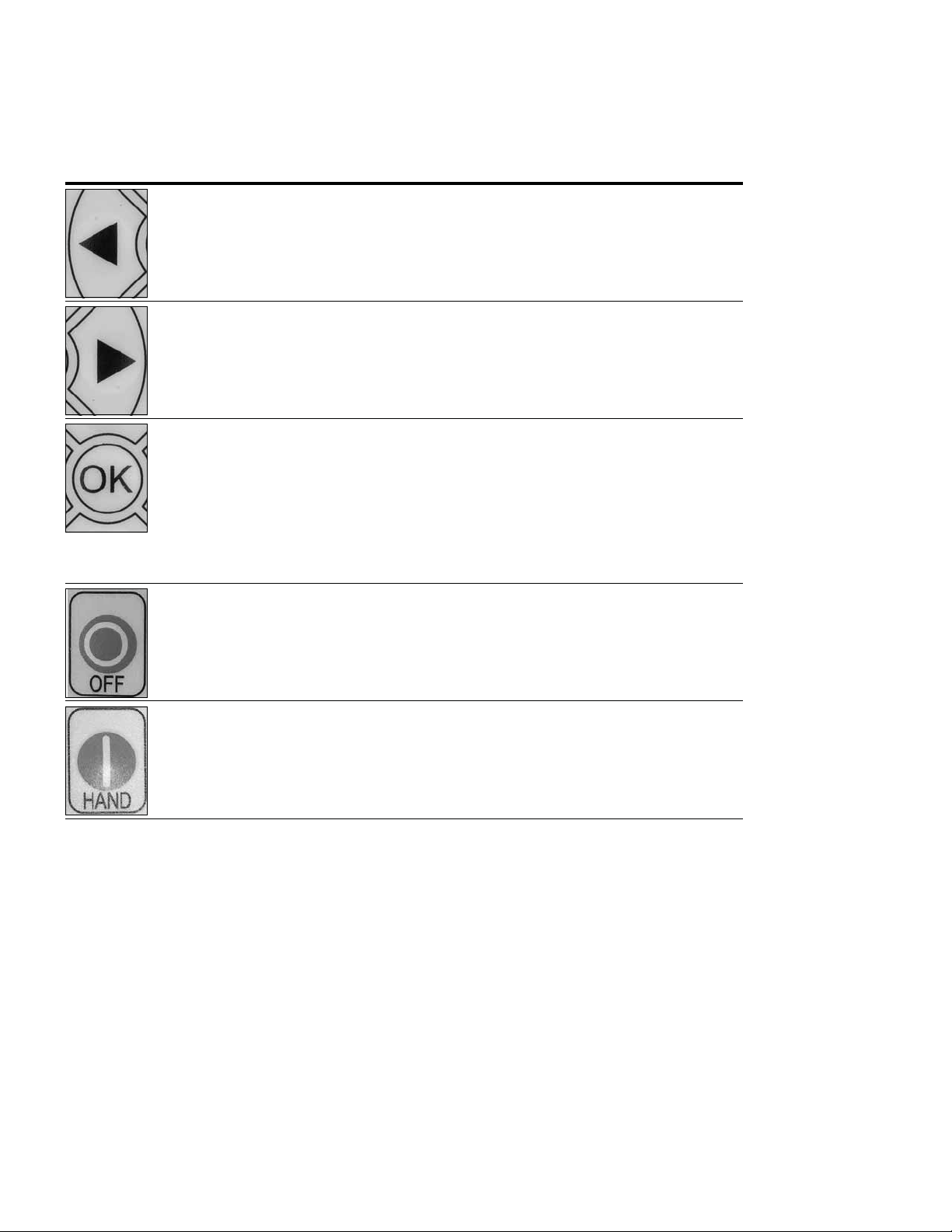
Programmable
Soft Key 2
Change Control
Place to Auto
Move Cursor
Right
Start/Hand Button
Stop/Off Button
Back/Reset
Button
Increase
Value Scroll
Menu Up
Programmable
Soft Key 1
Decrease Value
Scroll Menu Down
Move Cursor
Left
Enter Menu
Conrm Selection
Rating Label
Figure 2. Rating Label
Keypad Overview
Figure 3. Keypad and Display
Carton Labels (U.S. and Europe)
Same as rating label shown above.
2 Variable Speed Drives Series III LIT-12012996—April 2018 www.johnsoncontrols.com
Page 5
Step 2—Keypad Operation Overview
The keypad is the interface between the drive and the user.
It features an LCD display, 3 LED lights and 11 buttons. With
the control keypad, it is possible to control the speed of a
motor, to supervise the state of the equipment and to set the
frequency converter’s parameters. See Figure 3.
Keypad Buttons
Step 2—Keypad Operation Overview
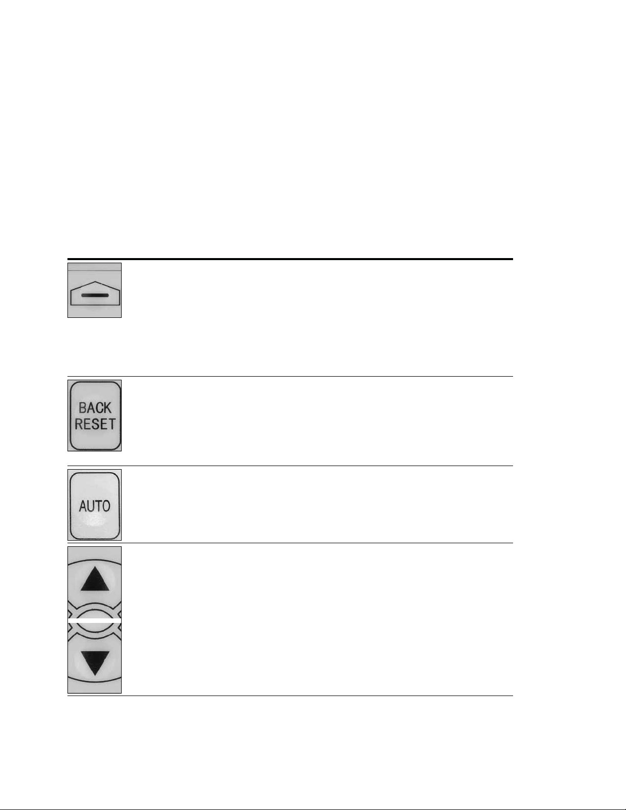
Buttons Description
Table 2. Keypad Buttons
Icon Button Description
Soft Key 1,
Soft Key 2
Back/Reset Back/Reset:
Auto Auto:
Soft Key 1, Soft Key 2:
The functions of these two buttons shall be the following:
Forward/Reverse, this shall change motor’s run direction.
Reset, this shall ask MCU to reset after some parameters are modified.
• Menu, this shall return to main menu.
• Details, this shall display the details of the fault.
• Bypass, this shall make drive go into bypass.
• Jog, this shall activate jog.
• Favorite, this shall add this parameter to the Favorite menu.
• Delete, this shall delete this parameter from the Favorite menu.
This button has three integrated functions. The button operates as backward button during
normal mode.
In edit mode, it is used as cancel operate. It is also used to reset faults when faults occur.
• Backs up one step.
• Cancels Modify in edit mode.
• Resets the active faults (all the active faults shall be reset by pressing this button
more than 2s in any page).
This button switches the drive into the auto control place.
Up
Down
Up and Down Arrows:
• Move either up or down a menu list to select the desired menu item.
• Editing a parameter bit by bit, while the active digit is scrolled.
• Increase/decrease the reference value of the selected parameter.
• In parameter comparison mode, scroll through the parameters of which current value
is different from comparison parameter value.
• In parameter page when in read mode, move to the previous or next brother
parameter of this parameter.
Variable Speed Drives Series III LIT-12012996—April 2018 www.johnsoncontrols.com 3
Page 6
Step 2—Keypad Operation Over view
Table 2. Keypad Buttons, continued
Icon Button Description
Left Left Arrow:
• Navigation button, movement to left when editing a parameter digit by digit.
• Backs up one step.
Right Right Arrow:
• Enter parameter group mode.
• Enter parameter mode from group mode.
• Enter parameter whole edit mode when this parameter can be written.
• Enter parameter bit by bit edit mode from whole edit mode.
• Navigation button, movement to right when editing a parameter bit by bit.
OK OK:
• To clear all the Fault History if pressed for more than 5s (including 5s) in any page.
• This button is used in the parameter edit mode to save the parameter setting.
• To confirm the start-up list at the end of the Start-Up Wizard.
• To confirm the comparison item in parameters comparison mode.
The following is the same with Right key:
• Enter parameter whole edit mode when this parameter can be written.
• Enter parameter group mode.
• Enter parameter mode from group mode.
Stop/Off Stop/Off:
This button operates as the motor stop button for normal operation and places the drive in the
off control location. The Default is for this button to always be active. It can be changed in
Parameter P4.1.3 to only when “Keypad” is selected as the control source.
• Motor stop from the keypad.
• Transitions drive into an Off control location preventing start from any control source.
Start/Hand Start/Hand:
This button operates as motor start button for normal operation when the “Keypad” is
selected as the active control source, as well as selects the Hand control place location.
• When Keypad is the reference place after hitting the start button, it will jump directly
to the Keypad Ref Screen.
• Places drive into Hand Control place. Hitting start again if keypad is in the control
location will start the Drive.
4 Variable Speed Drives Series III LIT-12012996—April 2018 www.johnsoncontrols.com
Page 7
Step 2—Keypad Operation Overview
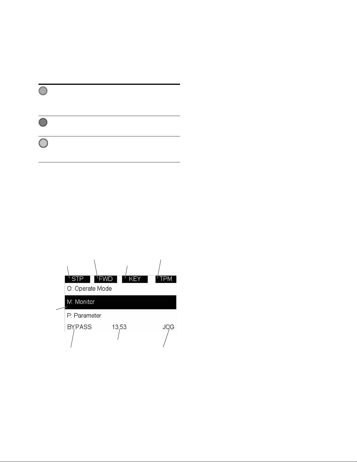
Drive Status
Direction Status
Control Place
Menu Location
Soft Key 2
Function Label
Soft Key 1
Function Label
Real Time Clock
(hh:mm)
Active
Selection
LED Lights
Table 3. LED State Indicators
Indicator Description
Run:
Indicates that the VFD is running and controlling the load in
Run
Drive or Bypass.
Blinks when a stop command has been given but the drive is
still ramping down.
Fault:
Turn on when there is one or more active drive fault(s).
Fault
Hand/OFF/Auto:
Hand: If the Hand or Off control place is selected,
Auto
turn off the light.
Auto: If the Auto control place is selected, turn on the light.
LCD Display
The keypad LCD indicates the status of the motor and the
drive and any faults in motor or drive functions. On the LCD,
the user sees information about the current location in the
menu structure and the item displayed.
Overview
Five lines shall be displayed in the screen. General view is as
following in Figure 4.
Figure 4. General View of LCD
The lines definition is as below:
The first line is State line, shows:
●
RUN / STP / NRD / FIM / TFM—If motor is running, the
run state shall display “RUN”, otherwise the state display
“STP”. “RUN” blinks when the stop command is sent but
the drive is decelerating. “NRD” is displayed if the drive is
not ready or does not have a signal. “FIM” is displayed to
indicate it is in Fire Mode and the drive is in a Run state.
“TFM” is displayed when in the Fire Mode Test Mode and
the drive is in a Run State.
●
FWD / REV / JOG—If the motor running the direction is
clockwise, it displays “FWD”, other wise displays “REV”
for counter clockwise. If “Jog” is displayed, it indicates
Jog mode is active.
●
KEY / I/O / BPS / RBP / BUS / OFF—If it is in bypass
currently, display “BPS”; when run command is given, it
will go to “RBP”; otherwise, if the current control source
is I/O terminal, display “I/O”. If it is keypad, then display
“KEY”; otherwise display “BUS.” When indicates “OFF”, it
indicates the drive will not accept a command from the
Hand or Auto Control place.
●
PAR / MON / FLT / OPE / QSW / FAV / TPM / BUx—
If the current page is parameter menu, display “PAR”;
If monitor menu, then display “MON”; If fault menu, then
display “FLT”; If operation menu, then display “OPE”;
If quick start wizard, then display “QSW”; If optional card
menu, then display “BOA”; If favorite menu, then display
“FAV”; If main menu, then display “TPM”. “BUx” indicates
the drive being a backup drive when in the redundant drive
system.
The second line is Code line, which shows the menu code.
The third line is Name line, which shows the menu name or
parameters name.
The fourth line is Value line, which shows the submenu
name or parameters value.
The fifth line is Soft key line, the functions of Soft key 1 and
Soft key 2 are changeable, and the real time is in the middle.
Variable Speed Drives Series III LIT-12012996—April 2018 www.johnsoncontrols.com 5
Page 8

Step 3—Menu Navigation
Step 3—Menu Navigation
Menu Structure
Table 4. Keypad Menu
Item Description Item Description
Monitor M1—Basic Fault F1—Active Fault
M2—IO Status F2—History Fault
M3—Optional Boards F3—Fault Log
M4—Energy savings Option Boards B1—Slot A
M5—FB Monitor Menu B2—Slot B
M6—PID Monitor Favorite
M7—Timer/Interval Control Operate Mode O1—Output Frequency
M8—User Defined Output O2—Freq Reference
M9—MWH Monitor O3—Motor Speed
M10—Multi-Monitoring O4—Motor Current
Parameters P1—Basic Parameter O5—Motor Torque
P2—Inputs O6—Motor Power
P3—Outputs O7—Motor Voltage
P4—Drive Control O8—DC-link Voltage
P5—Motor Control O9—Unit Temperature
P6—Protections O10—Motor Temperature
P7—PID Controller 1 R11—Keypad Reference
P8—PID Controller 2 R12—PID1 Keypad Set Point 1
P9—Fire Mode R13—PID1 Keypad Set Point 2
P10—Bypass Startup Wizard S—Startup Wizard
P11—Real Time Clock
P12—Communication
P13—System
Note: Will vary depending on application selected.
6 Variable Speed Drives Series III LIT-12012996—April 2018 www.johnsoncontrols.com
Page 9
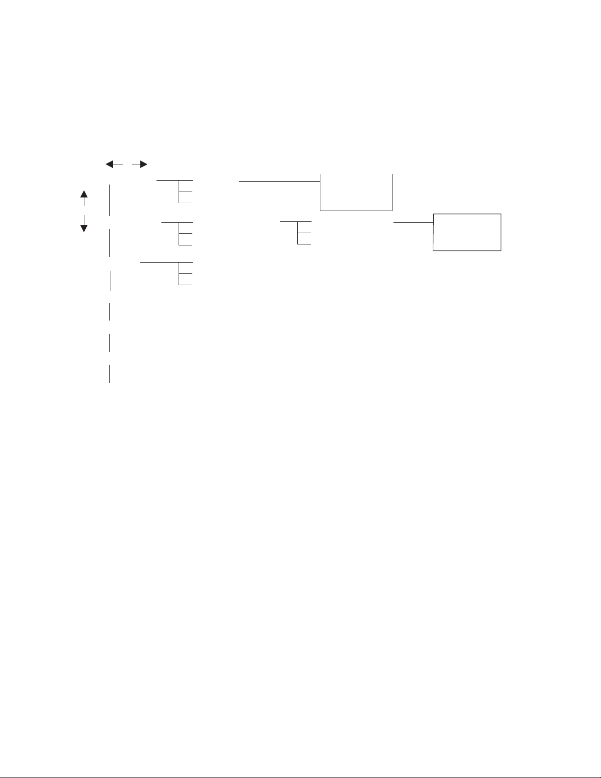
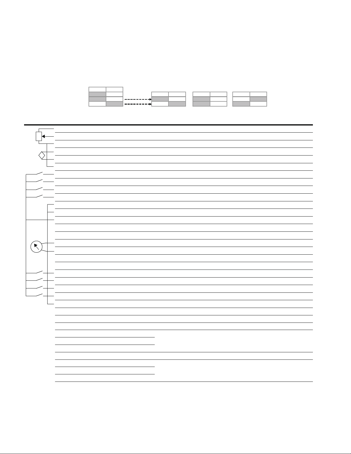
Menu Navigation
Back/left key Right/OK key
UP key
Down key
M – Monitor
P – Parameters
F – Fault
B – Optional Boards
T – Favorite
O – Operate Mode
…
…
…
M1 – Basic
M10 – Multi-Monitoring
P1 – Basic Parameters
P13 – System
F1 – Active Fault
F2 – History Fault
P1.1 – Min Frequency
P1.16 – Auto 2 Reference
M1.1
S – Startup Wizard
F3 – Fault Log
Output Frequency
0.00 Hz
P1.1
Min Frequency
0.00 Hz
This section provides basic instruction on navigating each
section in the menu structure.
Figure 5. Main Menu Navigation
Step 3—Menu Navigation
Variable Speed Drives Series III LIT-12012996—April 2018 www.johnsoncontrols.com 7
Page 10
Step 4—Startup Wizard
Step 4—Startup Wizard
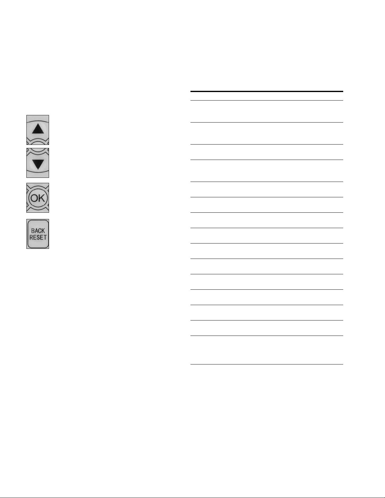
Startup Wizard
In the Startup Wizard, you will be prompted for essential
information needed by the drive so that it can start
controlling your process. In the Wizard, you will need
the following keypad buttons:
Up/Down buttons.
Use these to change value.
OK button.
Confirm selection with this button, and enter into
next question.
Back/Reset button.
If this button was pressed at the first question,
the Startup Wizard will be cancelled.
Once you have connected power to your frequency
converter, and the Startup Wizard is enabled, follow
these instructions to easily set up your drive.
Table 5. Startup Wizard Instructions
Item Description
1 Startup Wizard Press OK?
2 Application 0 = Basic
1 = PID
2 = Advanced
3 Language 0 = English
1 = ѝ᮷
2 = Deutsch
4 Real Time Clock yy.mm.dd
hh:mm:ss
5 Daylight Saving 0 = Off
1 = EU
2 = US
6 Min Frequency Min: 0.00Hz
Max: Max Frequency
7 Max Frequency Min: Min Frequency
Max: 400.00Hz
8 Motor Nom Current Min: 0.1A
Max: 500.0A
9 Current Limit Min: Ih*1/10
Max: Ih*2
10 Motor Nom Speed Min: Ih*1/10
Max: Ih*2
11 Motor PF Min: 0.30
Max: 1.0
12 Motor Nom Voltage Min: 180V
Max: 690V
13 Motor Nom Frequency Min: 30.00 Hz
Max: 400.00 Hz
14 Accel Time 1 Min: 0.1 sec
Max:3000.0 sec
15 Decel Time 1 Min: 0.1 sec
Max:3000.0 sec
16 Hand Control Place 0 = Keypad
1 = I/O Terminal Start 1
2 = I/O Terminal Start 2
3 = Fieldbus
8 Variable Speed Drives Series III LIT-12012996—April 2018 www.johnsoncontrols.com
Page 11

Table 5. Startup Wizard Instructions, continued
Item Description
17 Hand Reference 0 = AI1
1 = AI2
2 = Slot A: AI1
3 = Slot B: AI1
4 = AI1 Joystick
5 = AI2 Joystick
6 = Keypad
7 = Fieldbus
9 = Max Frequency
10 = AI1 + AI2
11 = AI1 –AI2
12 = AI2 –AI1
13 = AI1 * AI2
14 = AI1 or AI2
15 = Min(AI1,AI2)
16 = Max(AI1,AI2)
17 = PID1 Control Output
18 = PID2 Control Output
18 Auto 1 Control Place 0 = I/O Terminal Start 1
1 = Fieldbus
2 = I/O Terminal Start 2
3 = Keypad
19 Auto 1 Control Reference 0 = AI1
1 = AI2
2 = Slot A: AI1
3 = Slot B: AI1
4 = AI1 Joystick
5 = AI2 Joystick
6 = Keypad
7 = Fieldbus
9 = Max Frequency
10 = AI1 + AI2
11 = AI1 –AI2
12 = AI2 –AI1
13 = AI1 * AI2
14 = AI1 or AI2
15 = Min(AI1,AI2)
16 = Max(AI1,AI2)
17 = PID1 Control Output
18 = PID2 Control Output
20 Bypass Enabled 0 = Disabled
1 = Enabled
21 Application Mini-Wizard Press OK?
Step 4—Startup Wizard
Now the Startup Wizard is done. It won’t show again when
next power up. If you want to reset it, please set the Startup
Wizard (P13.1.17) or select it from the main menu screen to
enable and cycle the power to the drive.
Variable Speed Drives Series III LIT-12012996—April 2018 www.johnsoncontrols.com 9
Page 12

Step 5—Standard Parameter List
Step 5—Standard Parameter List
Introduction
The Basic Application is designed for preloaded application
sets for use with HVAC specific terminology and functions.
It has the patent Active Energy Control algorithm that will
improve your efficiency as well as minimize losses in your
motor throughout the defined speed range. It provides the
ability for the user to define its Hand and Auto control and
reference signals with the standard Off condition as well.
In addition there is the ability to scale the analog input and
output signals to be read based off the desired motor
response. There are also 8 digital inputs, 3 relay outputs, and
1 digital output that can be programmed to allow for control
schemes that require the drive to have certain functions. It
provides full customization on the motor control sequence
with the ability to be in frequency or speed control mode, and
tuning of the V/Hz curve can be selected. Drive/Motor
protections can be customized to defined actions for added
user control. Below is a list of other features that are
available in the Basic Application.
Basic Application includes functions:
●
Bypass control
●
Fire mode
●
Pre heat/cold weather mode
●
Hand/Off/Auto in individual button for easy change of
control mode
●
Programmable protections
●
Programmable digital/analog input/output function
●
Programmable start/stop signal logic
●
Voltage and current limiters
●
Energy Savings Calculator
●
Two independent set of Acceleration/Deceleration ramps
●
Skip frequency
●
Start source (Local/Remote control function)
●
Reference source
●
Flying start
●
Volts per Hertz control programmable
●
Real time clock—RTC time display
●
Auto restart on fault to drive or bypass
●
Programmable switching frequency
●
Multi-preset speeds
●
Fan control
●
DC brake
I/O Controls
“Terminal To Function” (TTF) Programming
The design behind the programming of the digital inputs in
the DH1 drive is to use “Terminal To Function”
programming, which is composed of multiple functions that
get assigned a digital input to that function. The parameters
in the drive are set up with specific functions and by defining
the digital input and slot in some cases, depending on which
options are available. For use of the drives control board
inputs, they will be referred to as DigIN:1 through DigIN:8.
When additional option cards are used, they will be defined
as DigIN:X:IOY:Z. The X indicates the slot that the card is
being installed in, which will be either A or B. The IOY
determines the type of card it is, which would be IO1 or IO5.
The Z indicates which input is being used on that available
option card.
“Function To Terminal” (FTT) Programming
The design behind the programming of the relay outputs and
digital output in the DH1 drive is to use “Function To
Terminal” programming. It is composed of a terminal, be it a
relay output or a digital output, that is assigned a parameter.
Within that parameter, it has different functions that can be
set.
The parameters of the Standard Application are explained in
Appendix A of application manual.
The explanations are arranged according to the parameter
number. For the DI function, we use Terminal programming
method to function (TTF), where there is a fixed input that
gets programmed to a list of functions. This allows for
multiple inputs to be used for different functions. Connecting
a certain input with a certain parameter function is done by
give a parameter an appropriate value. The value is formed
by the location of the input, either being on the standard
control board or an external option board and the slot it is
located in.
10 Variable Speed Drives Series III LIT-12012996—April 2018 www.johnsoncontrols.com
Page 13

Step 5—Standard Parameter List
Force Open/Force Close Selection
The Force Open Selection would make the selected function
always off. Essentially this is a virtual switch that is always
open. The Force Close Selection would make the selected
function always on. Essentially this is a virtual switch that is
always closed. These options are assigned to a function if we
want to force a state without using a hardware input.
The standard options are DigIn: Force Open—indication that
the parameter function is always going to be open, that being
said depending on the logic of the function this could mean
the function is always not active or always active. When the
selection of a function is DigIN: Force Closed—indication that
the parameter function is always going to be closed, that
being said again depending on the location of the function
this could mean the function is always active or not active.
Examples of these options would be ID190 Start Signal 1,
when set to “Force Open” and the drive is
looking at I/O terminals for control, in this case the drive
would never start since this Function is always Open. If this
function is set to “Force closed” the drive would always be
in a start mode when in that control location.
Example:
If we set Run Enable to Force Closed the drive is always
enabled. If we set the same function to Force Open the drive
would never be Enabled. If a Digital input is to be used to
activate this Run Enable the function should be assigned to
a hardware input (See below for DIGIN Selections).
DIGIN Selection
This allows Assignment of a hardware digital input to a
function, this is set in a format of DigIN:X where X is one
of the 8 Digital inputs on the Main control board.
Example:
If we set Run Enable to DigIN:6 the drive will be enabled
when digital input 6 (Terminal 8) is closed, and would not
be enabled when digital input 6 (Terminal 8) is open.
Option Board digIN Selection
This allows Assignment of a hardware digital input on an
option card to a function, this is set in a format of DigIN:
Y:IO1:X where Y is the slot the option card is inserted on the
Main control board and X is the Input on the Board and IO1 is
the type of option board used.
Example:
If we set Run Enable to DigIN:A:IO5:6 the drive will be
enabled when digital input 6 is closed on the IO5 option card
which is inserted in Slot A, and would not be enabled when
digital input 6 on the option card is open.
Timer Channel Selection
A Time Channel is a virtual path to link the digital output of a
timer function to a digital input function. To utilize this feature
a timer or interval would need to be assigned to a time
channel 1 through 3, and the input function to be controlled
would need to be assigned to the same time channel.
Example:
If we set Run Enable to DigIN:TimeChannel1 the drive will be
enabled when the timer assigned to Time Channel 1 is active
or High, and would not be enabled when the Time Channel is
inactive or Low.
Table 6. Drive Communication Ports
Port Communication
RJ45 Keypad Port
Upload/Download Parameters USB to RJ45
Remote Mount Keypad Ethernet
Upgrade Drive Firmware USB to RJ45
RJ45 Ethernet Port
Upload/Download Parameters Ethernet
BACnet/IP Communications Ethernet
Modbus TCP Communications Ethernet
RS-485 Serial Port
Upload/Download Parameters
Upgrade Drive Firmware Two-Wire Twisted Pair
Modbus RTU Communications Two-Wire Twisted Pair
BACnet MS/TP Communications Two-Wire Twisted Pair
SA Bus Two-Wire Twisted Pair
Note
1
Shielded wire recommended.
1
Variable Speed Drives Series III LIT-12012996—April 2018 www.johnsoncontrols.com 11
Page 14
Step 5—Standard Parameter List
Control I/O Configuration
●
Run 240 Vac and 24 Vdc control wiring in separate conduit
●
Communication wire to be shielded
Table 7. Analog Signals/Galaxy I/O Interface
External
Wiring
1
Signal
Pin
Name Signal
1 +10V Ref. Output Voltage — 10 Vdc Supply Source
Res
2 AI1+
2
Analog Input 1 0–10V Voltage Speed Reference (Programmable to 4 mA to 20 mA)
3 AI1– Analog Input 1 Ground — Analog Input 1 Common (Ground)
4 AI2+
i
5 AI2– Analog Input 2 Ground — Analog Input 2 Common (Ground)
2
Analog Input 2 4 mA to 20 mA Current Speed Reference (Programmable to 0–10V)
6 GND I/O Signal Ground — I/O Ground for Reference and Control
7 DIN5 Digital Input 5 Preset Speed B0 Sets frequency output to Preset Speed 1
8 DIN6 Digital Input 6 Fire Mode Enables drive into Fire Mode
9 DIN7 Digital Input 7 Bypass Start (TI–) Enables drive into Bypass mode waiting for drive start
10 DIN8 Digital Input 8 Force Auto (TI+) Input forces drive into Auto Control place
11 CMB DI5 to DI8 Common Grounded Allows source input
12 GND I/O Signal Ground — I/O Ground for Reference and Control
13 24V +24 Vdc Output — Control voltage output (100 mA max.)
14 DO1 Digital Output 1 Ready Shows the drive is ready to run
15 24Vo +24 Vdc Output — Control voltage output (100 mA max.)
16 GND I/O Signal Ground — I/O Ground for Reference and Control
17 AO1+ Analog Output 1 Output Frequency Shows Output frequency to motor 0–60 Hz (4 mA to 20 mA)
18 AO2+ Analog Output 2 Motor Current Shows Motor current of motor 0–FLA (4 mA to 20 mA)
19 24Vi +24 Vdc Input — External control voltage input
20 DIN1 Digital Input 1 Run Forward Input starts drive in forward direction (start enable)
21 DIN2 Digital Input 2 Run Reverse Input starts drive in reverse direction (start enable)
22 DIN3 Digital Input 3 External Fault Input causes drive to fault
23 DIN4 Digital Input 4 Fault Reset Input resets active faults
24 CMA DI1 to DI4 Common Grounded Allows source input
25 A/+ RS-485 Signal A — Fieldbus Communication (Modbus, BACnet, SA Bus)
26 B/– RS-485 Signal B — Fieldbus Communication (Modbus, BACnet, SA Bus)
27 R3NO Relay 3 Normally Open Fault Relay output 3 shows VFD is Faulted
28 R1NC Relay 1 Normally Closed Bypass Run Relay output 1 shows VFD is in a bypass run state
29 R1CM Relay 1 Common
30 R1NO Relay 1 Normally Open
31 R3CM Relay 3 Common Fault Relay output 3 shows VFD is Faulted
32 R2NC Relay 2 Normally Closed Run Relay output 2 shows VFD is in a drive run state
33 R2CM Relay 2 Common
34 R2NO Relay 2 Normally Open
Notes
1
The above wiring demonstrates a SINK configuration. It is important that CMA and CMB are wired to ground (as shown by dashed line).
If a SOURCE configuration is desired, wire 24 V to CMA and CMB and close the inputs to ground. When using the +10 V for AI1, it is
important to wire AI1—ground (as shown by dashed line). If using +10 V for AI1 or AI2, terminals 3, 5, and 6 need to be jumpered together.
2
AI1+ and AI2+ support 10K potentiometer.
Default
Setting Description
12 Variable Speed Drives Series III LIT-12012996—April 2018 www.johnsoncontrols.com
Page 15

Step 5—Standard Parameter List
Basic Application—Parameters List
On the next pages you will find the lists of parameters within the respective parameter
groups. The parameter descriptions are given in Appendix A of application manual. The
descriptions are arranged according to the parameter number.
Column explanations:
Code = Location indication on the keypad; shows the operator the present parameter number
Parameter = Name of parameter
Min = Minimum value of parameter
Max = Maximum value of parameter
Unit = Unit of parameter value; given if available
Default = Value preset by factory
ID = ID number of the parameter
Monitor
Table 8. Basic—M1
Code Parameter Min. Max. Unit Default ID Note
M1.1 Output Frequency Hz 1
M1.2 Freq Reference Hz 24
M1.3 Motor Speed rpm 2
M1.4 Motor Current A 3
M1.5 Motor Torque % 4
M1.6 Motor Power % 5
M1.7 Motor Voltage V 6
M1.8 DC-link Voltage V 7
M1.9 Unit Temperature °C 8
M1.10 Motor Temperature % 9
M1.11 Latest Fault Code 28
M1.12 Instant Motor Power kW 1686
M1.13 RTC Battery Status 583 0 = Not Installed
1 = Installed
2 = Change Battery
3 = OverVoltage
Notes
1
Parameter value can only be changed after the drive has stopped.
2
Parameter value will be set to be default when changing macros.
Variable Speed Drives Series III LIT-12012996—April 2018 www.johnsoncontrols.com 13
3
Input function is Level sensed.
4
Input function is Edge sensed.
5
Input function is Edge sensed when using StartP/StopP start logic.
Page 16

Step 5—Standard Parameter List
Table 9. IO Status—M2
Code Parameter Min. Max. Unit Default ID Note
M2.1 Analog Input 1 Varies 10
M2.2 Analog Input 2 Varies 11
M2.3 Analog Output 1 Varies 25
M2.4 Analog Output 2 Varies 575
M2.5 DI1, DI2, DI3 12
M2.6 DI4, DI5, DI6 13
M2.7 DI7, DI8 576
M2.8 DO1,Virtual RO1,Virtual RO2 14
M2.9 RO1, RO2, RO3 557
Table 10. Optional Boards—M3
Code Parameter Min. Max. Unit Default ID Note
M3.1 PT100 Temperature °C 1000.0 27
Table 11. Energy Savings—M4
Code Parameter Min. Max. Unit Default ID Note
2
M4.1
Energy Savings Varies 0.000 2120
Table 12. FB Monitor Menu—M5
Code Parameter Min. Max. Unit Default ID Note
M5.1 Control Board DIDO Status 2209 Bit 0 = DIN1 Status
Bit 1 = DIN2 Status
Bit 2 = DIN3 Status
Bit 3 = DIN4 Status
Bit 4 = DIN5 Status
Bit 5 = DIN6 Status
Bit 6 = DIN7 Status
Bit 7 = DIN8 Status
Bit 8 = DO1 Status
Bit 9 = RO1 Status
Bit 10 = RO2 Status
Bit 11 = RO3 Status
Bit 12 = Slot A with Board
Bit 13 = Slot B with Board
Bit 14–15 = Not used
3
Notes
1
Parameter value can only be changed after the drive has stopped.
2
Parameter value will be set to be default when changing macros.
14 Variable Speed Drives Series III LIT-12012996—April 2018 www.johnsoncontrols.com
Input function is Level sensed.
4
Input function is Edge sensed.
5
Input function is Edge sensed when using StartP/StopP start logic.
Page 17

Step 5—Standard Parameter List
Table 11. FB Monitor Menu—M5, continued
Code Parameter Min. Max. Unit Default ID Note
M5.2 SlotA DIDO Status 2210 Bit 0 = IO1_DIN1 Status
M5.3 SlotB DIDO Status 2211 Bit 0 = IO1_DIN1 Status
M5.4 Application Status Word 29 Bit 0 = MC Ready
Bit 1 = IO1_DIN2 Status
Bit 2 = IO1_DIN3 Status
Bit 3 = IO1_DO1 Status
Bit 4 = IO1_DO2 Status
Bit 5 = IO1_DO3 Status
Bite 6 = IO3_RO1 Status
Bit 7 = IO3_RO2 Status
Bit 8 = IO3_RO3 Status
Bit 9 = IO5_AC1 Status
Bit 10 = IO5_AC2 Status
Bit 11 = IO5_AC3 Status
Bit 12 = IO5_AC4 Status
Bit 13 = IO5_AC5 Status
Bit 14 = IO5_AC6 Status
Bit 15 = Not Used
Bit 1 = MC_Run
Bit 2 = MC_Fault
Bit 3 = FB_Ref_Active
Bit 4 = MC_Stopping
Bit 5 = MC_Reverse
Bit 6 = MC_Warning/AR-Fault
Bit 7 = MC_ZeroSpeed
Bit 8 = I/O Control Indicate
Bit 9 = Panel Control Indicator
Bit 10 = Panel Fieldbus Indicator
Bit 11 = MC_DC_Brake
Bit 12 = RunEnable
Bit 13 = Run Bypass
Bit 14 = Ext Brake Control
Bit 15 = Bypass Mode
Notes
1
Parameter value can only be changed after the drive has stopped.
2
Parameter value will be set to be default when changing macros.
Variable Speed Drives Series III LIT-12012996—April 2018 www.johnsoncontrols.com 15
3
Input function is Level sensed.
4
Input function is Edge sensed.
5
Input function is Edge sensed when using StartP/StopP start logic.
Page 18

Step 5—Standard Parameter List
Table 11. FB Monitor Menu—M5, continued
Code Parameter Min. Max. Unit Default ID Note
M5.5 Standard Status Word 2414 Bit 0 = See PAR ID 2415
Table 13. User Defined Output—M8
Code Parameter Min. Max. Unit Default ID Note
M8.1 Output Varies 2445
M8.2 Reference Varies 2447
(default = Ready)
Bit 1 = See PAR ID 2416
(default = Run)
Bit 2 = See PAR ID 2417
(default = Fault)
Bit 3 = See PAR ID 2418
(default = Fault Invert)
Bit 4 = See PAR ID 2419
(default = Warning)
Bit 5 = See PAR ID 2420
(default = Reversed)
Bit 6 = See PAR ID 2421
(default = At Speed)
Bit 7 = See PAR ID 2422
(default = Zero Frequency)
Bit 8–15 = Not Used
Table 14. MWH Monitor—M9
Code Parameter Min. Max. Unit Default ID Note
M9.1 Total MWh Count Mwh 601
M9.2 Total Power Day Count 603
M9.3 Total Power Hr Count 606
M9.4 Trip MWh Count Mwh 604
M9.5 Trip Power Day Count 636
M9.6 Trip Power Hr Count 637
Table 15. Multi-Monitoring—M10
Code Parameter Min. Max. Unit Default ID Note
M10.1 Multi-Monitoring 0, 1, 2 30
3
Notes
1
Parameter value can only be changed after the drive has stopped.
2
Parameter value will be set to be default when changing macros.
16 Variable Speed Drives Series III LIT-12012996—April 2018 www.johnsoncontrols.com
Input function is Level sensed.
4
Input function is Edge sensed.
5
Input function is Edge sensed when using StartP/StopP start logic.
Page 19

Step 5—Standard Parameter List
Table 16. Operate Mode—O
Code Parameter Min. Max. Unit Default ID Note
O1 Output Frequency Hz 0 1
O2 Freq Reference Hz 0 24
O3 Motor Speed rpm 0 2
O4 Motor Current A 0 3
O5 Motor Torque % 0 4
O6 Motor Power % 0 5
O7 Motor Voltage V 0 6
O8 DC-link Voltage V 0 7
O9 Unit Temperature °C 0 8
O10 Motor Temperature % 0 9
2
R11
Parameters
Keypad Reference PAR ID 101 PAR ID 102 Hz 0 141
Table 17. Basic Parameters—P1
Code Parameter Min. Max. Unit Default ID Note
12
P1.1
P1.2
P1.3
P1.4
P1.5
P1.6
P1.7
P1.8
P1.9
P1.10
12
2
2
1
1
1
1
1
Min Frequency 0.00 See Par ID 102 Hz 0.00 101
Max Frequency See Par ID 101 400.00 Hz Varies 102
Accel Time 1 0.1 3000.0 s 20.0 103
Decel Time 1 0.1 3000.0 s 20.0 104
Motor Nom Current DriveNomCurr
CT*1/10
DriveNomCurr
CT*2
A DriveNomCurrCT 486
Motor Nom Speed 300 20000 rpm Varies 489
Motor PF 0.30 1.00 0.85 490
Motor Nom Voltage 180 690 V Varies 487
Motor Nom Frequency 8.00 400.00 Hz Varies 488
12
HOA Source 0 2465 0 = I/O Terminal/Keypad/Fieldbus
1 = Keypad
2 = IO Terminal
3 = Fieldbus
2
P1.11
Hand Control Place 0 1695 0 = Keypad
1 = I/O Terminal Start 1
2 = I/O Terminal Start 2
3 = Fieldbus
Notes
1
Parameter value can only be changed after the drive has stopped.
2
Parameter value will be set to be default when changing macros.
Variable Speed Drives Series III LIT-12012996—April 2018 www.johnsoncontrols.com 17
3
Input function is Level sensed.
4
Input function is Edge sensed.
5
Input function is Edge sensed when using StartP/StopP start logic.
Page 20

Step 5—Standard Parameter List
Table 17. Basic Parameters—P1, continued
Code Parameter Min. Max. Unit Default ID Note
12
P1.12
P1.13
P1.14
P1.15
P1.16
Hand Reference 6 136 0 = AI1
1 = AI2
2 = Slot A: AI1
3 = Slot B: AI1
6 = Keypad
7 = Fieldbus Ref
9 = Max Frequency
10 = AI1 + AI2
11 = AI1 - AI2
12 = AI2 - AI1
13 = AI1 * AI2
14 = AI1 or AI2
15 = MIN(AI1,AI2)
16 = MAX(AI1,AI2)
2
Auto 1 Control Place 0 135 0 = I/O Terminal Start 1
1 = Fieldbus
2 = I/O Terminal Start 2
3 = Keypad
12
Auto 1 Reference 1 137 See Par ID 136
2
Auto 2 Control Place 1 138 See Par ID 135
12
Auto 2 Reference 7 139 See Par ID 136
Inputs
Table 18. Basic Setting—P2.1
Code Parameter Min. Max. Unit Default ID Note
2
P2.1.4
P2.1.5
AI Ref Scale Min Value 0.00 See Par ID 145 Hz 0.00 144
2
AI Ref Scale Max Value See Par ID 144 400.00 Hz 0.00 145
Table 19. Digital Input—P2.2
Code Parameter Min. Max. Unit Default ID Note
12
P2.2.1
IO Terminal 1 Start Stop
Logic
0 143 0 = Forward - Reverse
1 = Start - Reverse
2 = Start - Enable
3 = Start Pulse - Stop Pulse
3
Notes
1
Parameter value can only be changed after the drive has stopped.
2
Parameter value will be set to be default when changing macros.
18 Variable Speed Drives Series III LIT-12012996—April 2018 www.johnsoncontrols.com
Input function is Level sensed.
4
Input function is Edge sensed.
5
Input function is Edge sensed when using StartP/StopP start logic.
Page 21

Step 5—Standard Parameter List
Table 18. Digital Input—P2.2, continued
Code Parameter Min. Max. Unit Default ID Note
25
P2.2.2
P2.2.3
P2.2.4
P2.2.5
P2.2.6
P2.2.7
P2.2.8
P2.2.9
P2.2.10
P2.2.11
P2.2.12
IO Terminal 1 Start Signal 1 2 190 0 = DigIN:NormallyOpen
1 = DigIN:NormallyClose
2 = DigIN: 1
3 = DigIN: 2
4 = DigIN: 3
5 = DigIN: 4
6 = DigIN: 5
7 = DigIN: 6
8 = DigIN: 7
9 = DigIN: 8
10 = DigIN: A: IO1: 1
11 = DigIN: A: IO1: 2
12 = DigIN: A: IO1: 3
13 = DigIN: A: IO5: 1
14 = DigIN: A: IO5: 2
15 = DigIN: A: IO5: 3
16 = DigIN: A: IO5: 4
17 = DigIN: A: IO5: 5
18 = DigIN: A: IO5: 6
19 = DigIN: B: IO1: 1
20 = DigIN: B: IO1: 2
21 = DigIN: B: IO1: 3
22 = DigIN: B: IO5: 1
23 = DigIN: B: IO5: 2
24 = DigIN: B: IO5: 3
25 = DigIN: B: IO5: 4
26 = DigIN: B: IO5: 5
27 = DigIN: B: IO5: 6
31 = RO1 Function
32 = RO2 Function
33 = RO3 Function
34 = Virtual RO1 Function
35 = Virtual RO2 Function
25
IO Terminal 1 Start Signal 2 3 191 See Par ID 190
1 2
IO Terminal 2 Start Stop
0 2206 See Par ID 143
Logic
25
IO Terminal 2 Start Signal 1 2 2207 See Par ID 190
25
IO Terminal 2 Start Signal 2 3 2208 See Par ID 190
12
Thermistor Input Select 0 881 0 = Digital Input
1 = Thermistor Input
23
Reverse 0 198 See Par ID 190
23
Ext. Fault 1 NO 4 192 See Par ID 190
23
Ext. Fault 1 NC 1 193 See Par ID 190
2
Ext. Fault 1 Text 0 2297 0 = External Fault
1 = Vibration Cut out
2 = High Motor temp
3 = Low Pressure
4 = High Pressure
5 = Low Water
6 = Damper Interlock
7 = Run Enable
8 = Freeze Stat Trip
9 = Smoke Detect
10 = Seal Leakage
11 = Rod Breakage
23
Ext. Fault 2 NO 0 2293 See Par ID 190
Notes
1
Parameter value can only be changed after the drive has stopped.
2
Parameter value will be set to be default when changing macros.
Variable Speed Drives Series III LIT-12012996—April 2018 www.johnsoncontrols.com 19
3
Input function is Level sensed.
4
Input function is Edge sensed.
5
Input function is Edge sensed when using StartP/StopP start logic.
Page 22

Step 5—Standard Parameter List
Table 18. Digital Input—P2.2, continued
Code Parameter Min. Max. Unit Default ID Note
23
P2.2.13
P2.2.14
P2.2.15
P2.2.16
P2.2.17
P2.2.18
P2.2.19
P2.2.20
P2.2.21
P2.2.22
P2.2.23
P2.2.24
P2.2.25
P2.2.26
P2.2.27
P2.2.28
P2.2.29
P2.2.30
P2.2.32
P2.2.33
P2.2.34
P2.2.35
P2.2.40
P2.2.42
P2.2.43
P2.2.44
Ext. Fault 2 NC 1 2294 See Par ID 190
2
Ext. Fault 2 Text 1 2298 See Par ID 2297
23
Ext. Fault 3 NO 0 2295 See Par ID 190
23
Ext. Fault 3 NC 1 2296 See Par ID 190
2
Ext. Fault 3 Text 2 2299 See Par ID 2297
24
Fault Reset 5 200 See Par ID 190
23
Run Enable 1 194 See Par ID 190
23
Preset Speed B0 6 205 See Par ID 190
23
Preset Speed B1 0 206 See Par ID 190
23
Preset Speed B2 0 207 See Par ID 190
23
Jog Enable 0 199 See Par ID 190
23
Accel/Decel Time Set 0 195 See Par ID 190
23
Accel/Decel Prohibit 0 201 See Par ID 190
24
No Access To Param 0 215 See Par ID 190
23
Auto Control 9 196 See Par ID 190
23
Hand Control 0 197 See Par ID 190
23
Auto 1/2 Select 0 209 See Par ID 190
23
HOA On/Off 1 2395 See Par ID 190
24
Parameter Set1/2 Sel 0 2312 See Par ID 190
23
AI Ref Source Select 0 208 See Par ID 190
24
Bypass Start 8 218 See Par ID 190
23
Bypass Overload 0 1246 See Par ID 190
23
DC Brake Active 0 202 See Par ID 190
23
Fire Mode 7 220 See Par ID 190
23
Fire Mode Ref 1/2 Select 0 221 See Par ID 190
23
Fire Mode Reverse 0 2119 See Par ID 190
Table 19. Preset Speed—P2.3
Code Parameter Min. Max. Unit Default ID Note
2
P2.3.1
P2.3.2
P2.3.3
P2.3.4
P2.3.5
P2.3.6
P2.3.7
P2.3.8
Notes
1
Parameter value can only be changed after the drive has stopped.
2
Parameter value will be set to be default when changing macros.
20 Variable Speed Drives Series III LIT-12012996—April 2018 www.johnsoncontrols.com
Preset Speed 1 0.00 See Par ID 102 Hz 5.00 105
2
Preset Speed 2 0.00 See Par ID 102 Hz 10.00 106
2
Preset Speed 3 0.00 See Par ID 102 Hz 15.00 118
2
Preset Speed 4 0.00 See Par ID 102 Hz 20.00 119
2
Preset Speed 5 0.00 See Par ID 102 Hz 25.00 120
2
Preset Speed 6 0.00 See Par ID 102 Hz 30.00 121
2
Preset Speed 7 0.00 See Par ID 102 Hz 35.00 122
2
Jog Reference See Par ID 101 See Par ID 102 Hz 0.00 117
3
Input function is Level sensed.
4
Input function is Edge sensed.
5
Input function is Edge sensed when using StartP/StopP start logic.
Page 23

Step 5—Standard Parameter List
Table 20. AI1 Settings—P2.4
Code Parameter Min. Max. Unit Default ID Note
P2.4.1 AI1 Mode 1 222 0 = 0–20 mA
2
P2.4.2
P2.4.3
P2.4.4
P2.4.5
P2.4.6
AI1 Signal Range 0 175 0 = 0–100%/0–20 mA/0–10 V
2
AI1 Custom Min 0.00 See Par ID 177 % 0.00 176
2
AI1 Custom Max See Par ID 176 100.00 % 100.00 177
2
AI1 Filter Time 0.00 10.00 s 0.10 174
2
AI1 Signal Invert 0 181 0 = Not Inverted
Table 21. AI2 Settings—P2.5
Code Parameter Min. Max. Unit Default ID Note
P2.5.1 AI2 Mode 0 223 0 = 0–20 mA
2
P2.5.2
P2.5.3
P2.5.4
P2.5.5
P2.5.6
AI2 Signal Range 1 183 0 = 0–100%/0–20 mA/
2
AI2 Custom Min 0.00 See Par ID 185 % 0.00 184
2
AI2 Custom Max See Par ID 184 100.00 % 100.00 185
2
AI2 Filter Time 0.00 10.00 s 0.10 182
2
AI2 Signal Invert 0 189 See Par ID 181
1 = 0–10 V
1 = 20–100%/4–20 mA/2–10 V
2 = Customized
1 = Inverted
1 = 0–10 V
2 = -10– +10 V
0 = 0–10 V/-10–10 V
1 = 20–100%/4–20 mA/
1 = 2–10 V/-6–10 V
2 = Customized
Table 22. Digital Output—P3.1
Code Parameter Min. Max. Unit Default ID Note
2
P3.1.1
DO1 Function 1 151 0 = Not Used
1 = Ready
2 = Run
3 = Fault
4 = Fault Invert
5 = Warning
6 = Reversed
7 = At Speed
8 = Zero Frequency
9 = Freq Limit 1 Superv
10 = Freq Limit 2 Superv
13 = OverHeat Fault
14 = OverCurrent Regular
15 = OverVoltage Regular
16 = UnderVoltage Regular
17 = 4mA Ref Fault/Warning
20 = Torq Limit Superv
21 = Ref Limit Superv
22 = Control from I/O
23 = Un-Requested Rotation
23 = Direction
24 = Thermistor Fault Output
3
Notes
1
Parameter value can only be changed after the drive has stopped.
2
Parameter value will be set to be default when changing macros.
Input function is Level sensed.
4
Input function is Edge sensed.
5
Input function is Edge sensed when using StartP/StopP start logic.
Variable Speed Drives Series III LIT-12012996—April 2018 www.johnsoncontrols.com 21
Page 24

Step 5—Standard Parameter List
Table 22. Digital Output—P3.1, continued
Code Parameter Min. Max. Unit Default ID Note
2
P3.1.1
,
continued
P3.1.2
P3.1.3
P3.1.4
P3.1.5
P3.1.6
P3.1.7
P3.1.8
P3.1.9
P3.1.10
P3.1.11
P3.1.12
P3.1.13
DO1 Function 1 151 25 = Fire Mode
2
RO1 Function 62 152 See Par ID 151
2
RO1 On Delay 0.0 320.0 s 0.0 2112
2
RO1 Off Delay 0.0 320.0 s 0.0 2113
2
RO2 Function 2 153 See Par ID 151
2
RO2 On Delay 0.0 320.0 s 0.0 2114
2
RO2 Off Delay 0.0 320.0 s 0.0 2115
2
RO3 Function 3 538 See Par ID 151
2
RO3 On Delay 0.0 320.0 s 0.0 2116
2
RO3 Off Delay 0.0 320.0 s 0.0 2117
2
RO3 Reverse 0 2118 0 = No
2
Virtual RO1 Function 0 2463 See Par ID 151
2
Virtual RO2 Function 0 2464 See Par ID 151
26 = In Bypass Mode
27 = Ext Fault/Warning
28 = Auto Control
29 = Jog Speed Select
30 = Motor Therm Protection
31 = FB Digital Input 1
32 = FB Digital Input 2
33 = FB Digital Input 3
34 = FB Digital Input 4
40 = Power Limit Superv
41 = Temp Limit Superv
42 = Analog Input Superv
51 = Motor Current 1 Supv
52 = Motor Current 2 Supv
53 = Second AI Limit Supv
54 = DC Charge Switch Close
55 = Preheat Active
56 = Cold Weather Active
58 = 2th Stage Ramp Frequency
58 = Active
59 = STO Fault Output
60 = Run Bypass/Drive
61 = Bypass Overload
62 = Bypass Run
1 = Yes
Table 23. Supervisions—P3.2
Code Parameter Min. Max. Unit Default ID Note
2
P3.2.1
Freq Limit 1 Supv 0 154 0 = No Limit
1 = Low Limit Superv
2 = High Limit Superv
2
P3.2.2
P3.2.3
P3.2.4
P3.2.5
P3.2.6
P3.2.7
Notes
1
Parameter value can only be changed after the drive has stopped.
2
Parameter value will be set to be default when changing macros.
22 Variable Speed Drives Series III LIT-12012996—April 2018 www.johnsoncontrols.com
Freq Limit 1 Supv Val 0.00 See Par ID 102 Hz 0.00 155
2
Freq Limit 1 Supv Hyst 0.10 1.00 Hz 0.10 2200
2
Freq Limit 2 Supv 0 157 See Par ID 154
2
Freq Limit 2 Supv Val 0.00 See Par ID 102 Hz 0.00 158
2
Freq Limit 2 Supv Hyst 0.10 1.00 Hz 0.10 2201
2
Torque Limit Supv 0 159 See Par ID 154
3
Input function is Level sensed.
4
Input function is Edge sensed.
5
Input function is Edge sensed when using StartP/StopP start logic.
Page 25

Step 5—Standard Parameter List
Table 23. Supervisions—P3.2, continued
Code Parameter Min. Max. Unit Default ID Note
2
P3.2.8
P3.2.9
P3.2.10
P3.2.11
P3.2.12
P3.2.13
P3.2.14
P3.2.15
P3.2.16
P3.2.17
P3.2.18
P3.2.19
P3.2.20
P3.2.21
P3.2.22
P3.2.23
P3.2.24
P3.2.25
P3.2.26
P3.2.27
P3.2.28
P3.2.29
P3.2.30
P3.2.31
P3.2.32
Torque Limit Supv Val -1000.0 1000.0 % 100.0 160
2
Torque Limit Supv Hyst 1.0 5.0 % 1.0 2202
2
Ref Limit Supv 0 161 See Par ID 154
2
Ref Limit Supv Val 0.00 See Par ID 102 Hz 0.00 162
2
Ref Limit Supv Hyst 0.10 1.00 Hz 0.10 2203
2
Temp Limit Supv 0 165 See Par ID 154
2
Temp Limit Supv Val -10.0 75.0 °C 40.0 166
2
Temp Limit Supv Hyst 1.0 10.0 °C 1.0 2204
2
Power Limit Supv 0 167 See Par ID 154
2
Power Limit Supv Val -200.0 200.0 % 0.0 168
2
Power Limit Supv Hyst 0.1 10.0 % 0.1 2205
2
AI Supv Select 0 170 0 = AI1
2
AI Limit Supv 0 171 See Par ID 154
2
AI Limit Supv Val 0.00 100.00 % 0.00 172
2
AI Supv Hyst 1.00 10.00 % 1.00 2198
2
Motor Current 1 Supv 0 2189 See Par ID 154
2
Motor Current 1 Supv Value 0.0 DriveNomCurr
A DriveNomCurrCT 2190
CT*2
2
Motor Current 1 Supv Hyst 0.1 1.0 A 0.1 2196
2
Motor Current 2 Supv 0 2191 See Par ID 154
2
Motor Current 2 Supv Value 0.0 DriveNomCurr
A DriveNomCurrCT 2192
CT*2
2
Motor Current 2 Supv Hyst 0.1 1.0 A 0.1 2197
2
Second AI Supv Select 0 2193 See Par ID 170
2
Second AI Limit Supv 0 2194 See Par ID 154
2
Second AI Limit Supv Val 0.00 100.00 % 0.00 2195
2
Second AI Supv Hyst 1.00 10.00 % 1.00 2199
1 = AI2
Notes
1
Parameter value can only be changed after the drive has stopped.
2
Parameter value will be set to be default when changing macros.
Variable Speed Drives Series III LIT-12012996—April 2018 www.johnsoncontrols.com 23
3
Input function is Level sensed.
4
Input function is Edge sensed.
5
Input function is Edge sensed when using StartP/StopP start logic.
Page 26

Step 5—Standard Parameter List
Table 24. Analog Output 1—P3.3
Code Parameter Min. Max. Unit Default ID Note
2
P3.3.1
P3.3.2
P3.3.3
P3.3.4
P3.3.5
P3.3.6
P3.3.7
AO1 Mode 0 227 See Par ID 222
2
AO1 Function 1 146 0 = Not Used
2
AO1 Minimum 1 149 0 = 0 V / 0 mA
2
AO1 Filter Time 0.00 10.00 s 1.00 147
2
AO1 Scale 10 1000 % 100 150
2
AO1 Inversion 0 148 See Par ID 181
2
AO1 Offset -100.00 100.00 % 0.00 173
1 = Output Frequency
2 = Freq Reference
3 = Motor Speed (0–Nom)
4 = Motor Current (0–Nom)
5 = Motor Torque (0–Nom)
6 = Motor Power (0–Nom)
7 = Motor Voltage (0–Nom)
8 = DC-Bus Voltage
19 = AI1
20 = AI2
21 = Output Freq (-2-+2N)
22 = Motor Torque (-2-+2N)
23 = Motor Power (-2-+2N)
24 = PT100 Temperature
33 = SlotA PT100 Temp Channel 1
34 = SlotA PT100 Temp Channel 2
35 = SlotA PT100 Temp Channel 3
36 = SlotB PT100 Temp Channel 1
37 = SlotB PT100 Temp Channel 2
38 = SlotB PT100 Temp Channel 3
39 = User Defined Output
40 = Motor Current (-2-+2N)
1 = 2 V / 4 mA
Table 25. Analog Output 2—P3.4
Code Parameter Min. Max. Unit Default ID Note
2
P3.4.1
P3.4.2
P3.4.3
P3.4.4
P3.4.5
P3.4.6
P3.4.7
Notes
1
Parameter value can only be changed after the drive has stopped.
2
Parameter value will be set to be default when changing macros.
AO2 Mode 0 228 See Par ID 222
2
AO2 Function 4 229 See Par ID 146
2
AO2 Minimum 1 232 See Par ID 149
2
AO2 Filter Time 0.00 10.00 s 1.00 230
2
AO2 Scale 10 1000 % 100 233
2
AO2 Inversion 0 231 See Par ID 181
2
AO2 Offset -100.00 100.00 % 0.00 234
3
Input function is Level sensed.
4
Input function is Edge sensed.
5
Input function is Edge sensed when using StartP/StopP start logic.
24 Variable Speed Drives Series III LIT-12012996—April 2018 www.johnsoncontrols.com
Page 27

Step 5—Standard Parameter List
Drive Control
Table 26. Basic Setting—P4.1
Code Parameter Min. Max. Unit Default ID Note
2
P4.1.1
P4.1.2
P4.1.3
P4.1.4
P4.1.5
P4.1.6 Change PhaseSequence
P4.1.7
P4.1.9
P4.1.10
P4.1.11
P4.1.12
P4.1.13
P4.1.14
P4.1.15
P4.1.16
P4.1.17
P4.1.18
Keypad Reference See Par ID 101 See Par ID 102 Hz 0.00 141
2
Keypad Direction 0 116 0 = Forward
1 = Reverse
2
Keypad Stop 1 114 0 = Enabled-Keypad Operation
1 = Always Enabled
2
Hand Key Enable 0 1724 0 = Enabled
1 = Disabled
1
Reverse Enable 0 1679 0 = Disabled
1 = Enabled
0 2515 0 = Change Disable
Motor
2
Power Up HOA Select 0 1685 0 = Hold Last
1 = Change Enable
1 = Hand Control
2 = Auto control
3 = Off
2
Run Delay Time 0 32500 s 0 2423
2
Start Mode 0 252 0 = Ramp
1 = Flying Start
2
Stop Mode 0 253 0 = Coasting
1 = Ramp
2
Ramp 1 Shape 0.0 10.0 s 0.0 247
2
Ramp 2 Shape 0.0 10.0 s 0.0 248
2
Accel Time 2 0.1 3000.0 s 10.0 249
2
Decel Time 2 0.1 3000.0 s 10.0 250
2
Power Loss Function 0 267 See Par ID 1679
2
Power Loss Time 0.3 5.0 s 2.0 268
1 2
2nd Stage Ramp Frequency See Par ID 101 See Par ID 102 Hz 30.00 2444
Table 27. Brake—P4.2
Code Parameter Min. Max. Unit Default ID Note
1 2
P4.2.1
P4.2.2
P4.2.3
P4.2.4
P4.2.5
DC-Brake Current DriveNomCurr
CT*15/100
1 2
Start DC-Brake Time 0.00 600.00 s 0.00 263
1 2
Stop DC-Brake Frequency 0.10 10.00 Hz 1.50 262
1 2
Stop DC-Brake Time 0.00 600.00 s 0.00 255
1 2
Brake Chopper Define 0 251 0 = Disabled
DriveNomCurr
CT*15/10
A DriveNomCurr
CT*1/2
254
1 = B(Run) T(Rdy)
2 = External
3 = B(Rdy) T(Rdy)
4 = B(Run) T(No)
1 2
P4.2.6
Flux Brake 0 266 0 = Off
1 = On
1 2
P4.2.7
Flux Brake Current ActiveMotor
NomCurr*1/10
Notes
1
Parameter value can only be changed after the drive has stopped.
2
Parameter value will be set to be default when changing macros.
See Par ID 107 A ActiveMotorNom
265
Curr*1/2
3
Input function is Level sensed.
4
Input function is Edge sensed.
5
Input function is Edge sensed when using StartP/StopP start logic.
Variable Speed Drives Series III LIT-12012996—April 2018 www.johnsoncontrols.com 25
Page 28

Step 5—Standard Parameter List
Table 28. Skip Frequency—P4.3
Code Parameter Min. Max. Unit Default ID Note
2
P4.3.1
P4.3.2
P4.3.3
P4.3.4
P4.3.5
P4.3.6
P4.3.7
Table 29. Energy Savings Calc—P4.4
Code Parameter Min. Max. Unit Default ID Note
P4.4.1
P4.4.2
P4.4.3
P4.4.4 Energy Savings Reset 2125 0 = Not Reset
Skip Range Ramp Factor 0.1 10.0 1.0 264
2
Skip F1 Low Limit 0.00 See Par ID 257 Hz 0.00 256
2
Skip F1 High Limit See Par ID 256 400.00 Hz 0.00 257
2
Skip F2 Low Limit 0.00 See Par ID 259 Hz 0.00 258
2
Skip F2 High Limit See Par ID 258 400.00 Hz 0.00 259
2
Skip F3 Low Limit 0.00 See Par ID 261 Hz 0.00 260
2
Skip F3 High Limit See Par ID 260 400.00 Hz 0.00 261
2
Currency 0 2122 0 = $
2
Energy Cost Varies 0.00 2123
2
Data Type 0 2124 0 = Cumulative
1 = £
2 = €
3 = ¥
4 = Rs
5 = R$
6 = Fr
7 = kr
1 = Daily Avg
2 = Weekly Avg
3 = Monthly Avg
4 = Yearly Avg
1 = Reset
Motor Control
Table 30. Basic Setting—P5.1
Code Parameter Min. Max. Unit Default ID Note
1 2
P5.1.1
P5.1.2
P5.1.3
P5.1.4
P5.1.5
P5.1.6
P5.1.7
P5.1.8
P5.1.9
Notes
1
Parameter value can only be changed after the drive has stopped.
2
Parameter value will be set to be default when changing macros.
Motor Control Mode 0 287 0 = Freq Control
1
Current Limit DriveNomCurr
CT*1/10
1 2
V/Hz Optimization 0 109 See Par ID 1679
1 2
V/Hz Ratio 3 108 0 = Linear
1 2
Field Weakening Point 8.00 400.00 Hz Varies 289
1 2
Voltage at FWP 10.00 200.00 % 100.00 290
1 2
V/Hz Mid Frequency 0.00 See Par ID 289 Hz Varies 291
1 2
V/Hz Mid Voltage 0.00 100.00 % 100.00 292
1 2
Zero Frequency Voltage 0.00 40.00 % 0.00 293
DriveNomCurr
CT*2
A DriveNomCurrCT*2 107
3
Input function is Level sensed.
4
Input function is Edge sensed.
5
Input function is Edge sensed when using StartP/StopP start logic.
1 = Speed Control
1 = Squared
2 = Programmable
3 = Linear + Flux Optimization
26 Variable Speed Drives Series III LIT-12012996—April 2018 www.johnsoncontrols.com
Page 29

Step 5—Standard Parameter List
Table 30. Basic Setting—P5.1, continued
Code Parameter Min. Max. Unit Default ID Note
2
P5.1.10
P5.1.11
P5.1.12
Protections
Table 31. Motor—P6.1
Code Parameter Min. Max. Unit Default ID Note
P6.1.1
P6.1.2
P6.1.3
P6.1.4
P6.1.5
P6.1.6
P6.1.7
P6.1.8
P6.1.9
P6.1.10
P6.1.11
P6.1.12
P6.1.13
P6.1.14
P6.1.15
P6.1.16
P6.1.17
Switching Frequency MinSwitchFreq MaxSwitchFreq kHz DefaultSwitch
2522
FreqCT
2
Sine Filter Enable 0 1665 See Par ID 1679
1 2
OverVoltage Control 1 294 See Par ID 1679
1 2
Output Phase Fault 2 308 0 = No Action
1 2
Ground Fault 2 309 See Par ID 308
2
Ground Fault Limit 0 30 % 15 2158
1 2
Motor Thermal Protection 2 310 See Par ID 308
2
Motor Thermal F0 Current 0.0 150.0 % 40.0 311
2
Motor Thermal Time 1 200 min 12 312
1 2
Stall Protection 0 313 See Par ID 308
2
Stall Current Limit 0.1 ActiveMotor
NomCurr*2
2
Stall Time Limit 1.0 120.0 s 15.0 315
2
Stall Frequency Limit 1.00 See Par ID 102 Hz 25.00 316
1 2
Underload Protection 0 317 See Par ID 308
2
Underload Fnom Torque 10.0 150.0 % 50.0 318
2
Underload F0 Torque 5.0 150.0 % 10.0 319
2
Underload Time Limit 2.00 600.00 s 20.00 320
1 2
Thermistor Fault Response 2 333 See Par ID 308
1 2
PT100 Fault Response 2 337 See Par ID 308
2
Preheat Mode 0 2159 See Par ID 1679
A ActiveMotorNom
Curr*13/10
314
1 = Warning
2 = Fault
3 = Fault, Coast
Notes
1
Parameter value can only be changed after the drive has stopped.
2
Parameter value will be set to be default when changing macros.
Variable Speed Drives Series III LIT-12012996—April 2018 www.johnsoncontrols.com 27
3
Input function is Level sensed.
4
Input function is Edge sensed.
5
Input function is Edge sensed when using StartP/StopP start logic.
Page 30

Step 5—Standard Parameter List
Table 31. Motor—P6.1, continued
Code Parameter Min. Max. Unit Default ID Note
2
P6.1.18
P6.1.19
P6.1.20
P6.1.21
Preheat Control Source 31 2160 0 = DigIN:NormallyOpen
1 = DigIN:NormallyClose
2 = DigIN: 1
3 = DigIN: 2
4 = DigIN: 3
5 = DigIN: 4
6 = DigIN: 5
7 = DigIN: 6
8 = DigIN: 7
9 = DigIN: 8
10 = DigIN: A: IO1: 1
11 = DigIN: A: IO1: 2
12 = DigIN: A: IO1: 3
13 = DigIN: A: IO5: 1
14 = DigIN: A: IO5: 2
15 = DigIN: A: IO5: 3
16 = DigIN: A: IO5: 4
17 = DigIN: A: IO5: 5
18 = DigIN: A: IO5: 6
19 = DigIN: B: IO1: 1
20 = DigIN: B: IO1: 2
21 = DigIN: B: IO1: 3
22 = DigIN: B: IO5: 1
23 = DigIN: B: IO5: 2
24 = DigIN: B: IO5: 3
25 = DigIN: B: IO5: 4
26 = DigIN: B: IO5: 5
27 = DigIN: B: IO5: 6
28 = Time Channel 1
29 = Time Channel 2
30 = Time Channel 3
31 = Drive Temperature
32 = SlotA PT100 Temp Channel 1
33 = SlotA PT100 Temp Channel 2
34 = SlotA PT100 Temp Channel 3
35 = SlotA Max PT100 Temp
36 = SlotB PT100 Temp Channel 1
37 = SlotB PT100 Temp Channel 2
38 = SlotB PT100 Temp Channel 3
39 = SlotB Max PT100 Temp
40 = SlotA and SlotB Max PT100
40 = Temp
2
Preheat Enter Temp 0.0 19.9 °C 10.0 2161
2
Preheat Quit Temp 20.0 40.0 °C 20.0 2162
2
Preheat Output Volt 0.0 20.0 % 2.0 2163
3
Notes
1
Parameter value can only be changed after the drive has stopped.
2
Parameter value will be set to be default when changing macros.
28 Variable Speed Drives Series III LIT-12012996—April 2018 www.johnsoncontrols.com
Input function is Level sensed.
4
Input function is Edge sensed.
5
Input function is Edge sensed when using StartP/StopP start logic.
Page 31

Step 5—Standard Parameter List
Table 32. Drive—P6.2
Code Parameter Min. Max. Unit Default ID Note
2
P6.2.1
P6.2.2
P6.2.3
P6.2.4
P6.2.5
P6.2.6
P6.2.7
P6.2.8
P6.2.9
P6.2.10
P6.2.11
P6.2.12
P6.2.13
P6.2.14
P6.2.15 Cold Weather Password 2129
P6.2.16 Under Temp Fault Override 2130 See Par ID 2118
P6.2.17
Line Start Lockout 2 750 0 = Disabled, No Change
1 = Enable, No Change
2 = Disabled, Changed
3 = Enable, Changed
2
Fault Reset Start 0 2483 0 = Start/Stop After Fault Reset
1 = Restart After Fault Reset
1 2
4mA Input Fault 0 306 0 = No Action
1 = Warning
2 = Warning: Previous Freq
3 = Warning: Preset Freq
4 = Fault
5 = Fault, Coast
1 2
4mA Fault Frequency 0.00 See Par ID 102 Hz 0.00 331
1 2
External Fault 2 307 See Par ID 308
1 2
Input Phase Fault 2 332 See Par ID 308
1 2
Uvolt Fault Response 2 330 See Par ID 308
1 2
Unit Under Temp Prot 2 1564 See Par ID 308
1 2
RTC Fault 1 955 See Par ID 308
1 2
Replace Battery Fault
1 1256 See Par ID 308
Response
1 2
Replace Fan Fault Response 1 1257 See Par ID 308
2
Cold Weather Mode 0 2126 See Par ID 1679
2
Cold Weather Volt. Level 0.0 20.0 % 2.0 2127
2
Cold Weather Time Out 0 10 min 3 2128
2
STO Fault Response 2 2427 0 = No Action
1 = Warning
2 = Fault
Table 33. Communication—P6.3
Code Parameter Min. Max. Unit Default ID Note
1 2
P6.3.1
Fieldbus Fault Response 2 334 0 = No Action
1 = Warning
2 = Fault
3 = Fault, Coast
4 = Warning, Coast
1 2
P6.3.2
P6.3.3
P6.3.4
OPTCard Fault Response 2 335 See Par ID 308
1 2
IP Address Confliction Resp 1 1678 See Par ID 308
1 2
Keypad Comm Fault
2 2157 See Par ID 308
Response
3
Notes
1
Parameter value can only be changed after the drive has stopped.
2
Parameter value will be set to be default when changing macros.
Variable Speed Drives Series III LIT-12012996—April 2018 www.johnsoncontrols.com 29
Input function is Level sensed.
4
Input function is Edge sensed.
5
Input function is Edge sensed when using StartP/StopP start logic.
Page 32

Step 5—Standard Parameter List
Table 34. Auto Restart—P6.4
Code Parameter Min. Max. Unit Default ID Note
2
P6.4.1
P6.4.2
P6.4.3
P6.4.4
P6.4.5
P6.4.6
P6.4.7
P6.4.8
P6.4.9
P6.4.10
Table 35. Fire Mode—P9
Code Parameter Min. Max. Unit Default ID Note
1 2
P9.1
1 2
P9.2
2
P9.3
2
P9.4
2
P9.5
P9.6 Fire Mode Test Enable 2443 See Par ID 1679
AR Wait Time 1.00 300.00 s 1.00 321
2
AR Trail Time 0.00 600.00 s 30.00 322
2
AR Start Function 0 323 0 = Flying Start
2
Undervoltage Attempts 0 10 1 324
2
OverVoltage Attempts 0 10 1 325
2
OverCurrent Attempts 0 3 0 326
2
4mA Fault Attempts 0 10 0 327
2
Motor Temp Fault Attempts 0 10 0 329
2
External Fault Attempts 0 10 0 328
2
Underload Attempts 0 10 0 336
Fire Mode Function 0 535 0 = Closing Contact
Fire Mode Ref Select
0 536 0 = Fire Mode Min Frequency
Function
Fire Mode Min Frequency See Par ID 101 See Par ID 102 Hz 15.00 537
Fire Mode Freq Ref 1 0.0 100.0 % 75.0 565
Fire Mode Freq Ref 2 0.0 100.0 % 100.0 564
1 = Ramp
1 = Opening Contact
1 = Fire Mode Ref
2 = Fieldbus Ref
3 = AI1
4 = AI2
5 = AI1 + AI2
3
Notes
1
Parameter value can only be changed after the drive has stopped.
2
Parameter value will be set to be default when changing macros.
30 Variable Speed Drives Series III LIT-12012996—April 2018 www.johnsoncontrols.com
Input function is Level sensed.
4
Input function is Edge sensed.
5
Input function is Edge sensed when using StartP/StopP start logic.
Page 33

Step 5—Standard Parameter List
Bypass
Table 36. Basic Setting—P10.1
Code Parameter Min. Max. Unit Default ID Note
12
P10.1.1
P10.1.2
P10.1.3
P10.1.4
P10.1.5
P10.1.6
P10.1.7
P10.1.8
P10.1.9
P10.1.10
P10.1.11
P10.1.12
P10.1.13
P10.1.14
P10.1.15
P10.1.16
P10.1.17
P10.1.18
P10.1.19
P10.1.20
P10.1.21
P10.1.22
P10.1.23
P10.1.24
P10.1.25
Bypass Enable 1 1418 See Par ID 1679
12
Bypass Start Delay 1 32765 s 1 544
12
Auto Bypass 1 542 See Par ID 1679
12
Auto Bypass Delay 0 32765 s 10 543
12
OverCurrent Bypass Enable 0 547 See Par ID 1679
12
IGBT Fault Bypass Enable 0 546 See Par ID 1679
12
4mA Fault Bypass Enable 0 548 See Par ID 1679
12
UnderVoltage Bypass
0 545 See Par ID 1679
Enable
12
OverVoltage Bypass Enable 0 549 See Par ID 1679
12
Motor OverTemp Bypass
0 1698 See Par ID 1679
Enable
12
UnderLoad Bypass Enable 0 1699 See Par ID 1679
12
External Bypass Enable 0 1700 See Par ID 1679
12
Charge Switch Fault Bypass
0 1701 See Par ID 1679
Enable
12
Saturation Trip Fault Bypass
0 1702 See Par ID 1679
Enable
12
Under Temp Fault Bypass
0 1703 See Par ID 1679
Enable
12
EEPROM Fault Bypass
0 1704 See Par ID 1679
Enable
12
FRAM Fault Bypass Enable 0 1705 See Par ID 1679
12
Watchdog Fault Bypass
0 1706 See Par ID 1679
Enable
12
Fan Cooling Fault Bypass
0 1707 See Par ID 1679
Enable
12
Keypad Com Fault Bypass
0 1708 0 = Disabled
Enable
12
Option Card Fault Bypass
0 1709 See Par ID 1679
Enable
12
RTC Clock Fault Bypass
0 1710 See Par ID 1679
Enable
12
Ctrl Board OverTemp Fault
0 1711 See Par ID 1679
Bypass Enable
12
Speed Search Start Fault
0 1712 See Par ID 1679
Bypass Enable
12
Fieldbus Fault Bypass
0 1713 See Par ID 1679
Enable
2 = Enabled
Notes
1
Parameter value can only be changed after the drive has stopped.
2
Parameter value will be set to be default when changing macros.
Variable Speed Drives Series III LIT-12012996—April 2018 www.johnsoncontrols.com 31
3
Input function is Level sensed.
4
Input function is Edge sensed.
5
Input function is Edge sensed when using StartP/StopP start logic.
Page 34

Step 5—Standard Parameter List
Communication
Table 37. FB Process Data Input Sel—P12.1
Code Parameter Min. Max. Unit Default ID Note
2
P12.1.1
P12.1.2
P12.1.3
P12.1.4
P12.1.5
P12.1.6
P12.1.7
P12.1.8
Table 38. FB Process Data Output Sel—P12.2
Code Parameter Min. Max. Unit Default ID Note
P12.2.1
P12.2.2
P12.2.3
P12.2.4
P12.2.5
P12.2.6
P12.2.7
P12.2.8
FB Process Data Input 1 Sel 0 2560 0 2533
2
FB Process Data Input 2 Sel 0 2560 2542 2534
2
FB Process Data Input 3 Sel 0 2560 2550 2535
2
FB Process Data Input 4 Sel 0 2560 103 2536
2
FB Process Data Input 5 Sel 0 2560 104 2537
2
FB Process Data Input 6 Sel 0 2560 107 2538
2
FB Process Data Input 7 Sel 0 2560 0 2539
2
FB Process Data Input 8 Sel 0 2560 0 2540
2
FB Process Data Output 1
1 1556
Sel
2
FB Process Data Output 2
2 1557
Sel
2
FB Process Data Output 3
3 1558
Sel
2
FB Process Data Output 4
4 1559
Sel
2
FB Process Data Output 5
5 1560
Sel
2
FB Process Data Output 6
6 1561
Sel
2
FB Process Data Output 7
7 1562
Sel
2
FB Process Data Output 8
28 1563
Sel
3
Notes
1
Parameter value can only be changed after the drive has stopped.
2
Parameter value will be set to be default when changing macros.
32 Variable Speed Drives Series III LIT-12012996—April 2018 www.johnsoncontrols.com
Input function is Level sensed.
4
Input function is Edge sensed.
5
Input function is Edge sensed when using StartP/StopP start logic.
Page 35

Step 5—Standard Parameter List
Table 38. FB Process Data Output Sel—P12.2, continued
Code Parameter Min. Max. Unit Default ID Note
2
P12.2.9
P12.2.10
P12.2.11
P12.2.12
P12.2.13
Standard Status Word Bit0
Function Select
2
Standard Status Word Bit1
Function Select
2
Standard Status Word Bit2
Function Select
2
Standard Status Word Bit3
Function Select
2
Standard Status Word Bit4
Function Select
1 2415 0 = Not Used
1 = Ready
2 = Run
3 = Fault
4 = Fault Invert
5 = Warning
6 = Reversed
7 = At Speed
8 = Zero Frequency
9 = Freq Limit 1 Superv
10 = Freq Limit 2 Superv
13 = OverHeat Fault
14 = OverCurrent Regular
15 = OverVoltage Regular
16 = UnderVoltage Regular
17 = 4mA Ref Fault/Warning
20 = Torq Limit Superv
21 = Ref Limit Superv
22 = Control from I/O
23 = Un-Requested Rotation
23 = Direction
24 = Thermistor Fault Output
25 = Fire Mode
26 = In Bypass Mode
27 = Ext Fault/Warning
28 = Auto Control
29 = Jog Speed Select
30 = Motor Therm Protection
31 = FB Digital Input 1
32 = FB Digital Input 2
33 = FB Digital Input 3
34 = FB Digital Input 4
40 = Power Limit Superv
41 = Temp Limit Superv
42 = Analog Input Superv
51 = Motor Current 1 Supv
52 = Motor Current 2 Supv
53 = Second AI Limit Supv
54 = DC Charge Switch Close
55 = Preheat Active
56 = Cold Weather Active
58 = 2th Stage Ramp Frequency
58 = Active
59 = STO Fault Output
60 = Run Bypass/Drive
61 = Bypass Overload
62 = Bypass Run
2 2416 See Par ID 2415
3 2417 See Par ID 2415
4 2418 See Par ID 2415
5 2419 See Par ID 2415
Notes
1
Parameter value can only be changed after the drive has stopped.
2
Parameter value will be set to be default when changing macros.
Variable Speed Drives Series III LIT-12012996—April 2018 www.johnsoncontrols.com 33
3
Input function is Level sensed.
4
Input function is Edge sensed.
5
Input function is Edge sensed when using StartP/StopP start logic.
Page 36

Step 5—Standard Parameter List
Table 38. FB Process Data Output Sel—P12.2, continued
Code Parameter Min. Max. Unit Default ID Note
P12.2.14 2Standard Status Word Bit5
Function Select
2
P12.2.15
Standard Status Word Bit6
Function Select
2
P12.2.16
Standard Status Word Bit7
Function Select
RS-485 Bus
Table 39. Basic Setting—P12.3.1
Code Parameter Min. Max. Unit Default ID Note
1
P12.3.1.1
Table 40. Modbus RTU—P12.3.2
Code Parameter Min. Max. Unit Default ID Note
P12.3.2.1
P12.3.2.2
P12.3.2.3
P12.3.2.4 Modbus RTU Protocol
P12.3.2.5 Comm Timeout Modbus RTU 0 60000 ms 10000 593
P12.3.2.6 Modbus RTU Fault
RS485 Comm Set 0 586 0 = Modbus RTU
1
Slave Address 1 247 1 587
1
Baud Rate 1 584 0 = 9600
1
Parity Type 2 585 0 = None
Status
Response
6 2420 See Par ID 2415
7 2421 See Par ID 2415
8 2422 See Par ID 2415
1 = BACnet MS/TP
2 = SA Bus
1 = 19200
2 = 38400
3 = 57600
4 = 115200
1 = Odd
2 = Even
588 0 = Initial
1 = Stopped
2 = Operational
3 = Faulted
0 2516 0 = in Fieldbus Control
1 = in all Control
Table 41. BACnet MS/TP—P12.3.3
Code Parameter Min. Max. Unit Default ID Note
1
P12.3.3.1
MSTP Baud Rate 2 594 0 = 9600
1 = 19200
2 = 38400
3 = 76800
4 = 115200
1
P12.3.3.2
P12.3.3.3
MSTP Device Address 0 127 1 595
1
MSTP Instance Number 0 4194302 0 596
P12.3.3.4 MSTP Comm Timeout 0 60000 ms 10000 598
P12.3.3.5 MSTP Protocol Status 599 0 = Stopped
1 = Operational
2 = Faulted
3
Notes
1
Parameter value can only be changed after the drive has stopped.
2
Parameter value will be set to be default when changing macros.
34 Variable Speed Drives Series III LIT-12012996—April 2018 www.johnsoncontrols.com
Input function is Level sensed.
4
Input function is Edge sensed.
5
Input function is Edge sensed when using StartP/StopP start logic.
Page 37

Step 5—Standard Parameter List
Table 41. BACnet MS/TP—P12.3.3, continued
Code Parameter Min. Max. Unit Default ID Note
P12.3.3.6 MSTP Fault Code 600 0 = None
2
P12.3.3.7
P12.3.3.8
MSTP Fault Response 0 2526 See Par ID 2516
1
MSTP Max Master 127 1537
Table 42. SA Bus—P12.3.4
Code Parameter Min. Max. Unit Default ID Note
12
P12.3.4.1
P12.3.4.2
P12.3.4.3
P12.3.4.4
SA Bus Baud Rate 2 1727 See Par ID 584
12
SA Bus Device Address 204 254 204 1726
12
SA Bus Instance Number 0 4194302 0 1728
2
SA Bus Comm Timeout 0 60000 10000 1730
P12.3.4.5 SA Bus Protocol Status 1731 See Par ID 599
2
P12.3.4.6
SA Bus Fault Response 0 1732 See Par ID 2516
1 = Sole Master
2 = Duplicate MAC ID
3 = Baud rate fault
EtherNet Bus
Table 43. Basic Setting—P12.4.1
Code Parameter Min. Max. Unit Default ID Note
1
P12.4.1.1
P12.4.1.2 Active IP Address 1507
P12.4.1.3 Active Subnet Mask 1509
P12.4.1.4 Active Default Gateway 1511
P12.4.1.5 MAC Address 1513
P12.4.1.6
P12.4.1.7
P12.4.1.8
P12.4.1.9
Table 44. Modbus TCP—P12.4.2
Code Parameter Min. Max. Unit Default ID Note
P12.4.2.1 Connection Limit 5 609
P12.4.2.2 Modbus TCP Unit ID 1 610
P12.4.2.3 Comm Timeout Modbus TCP 0 60000 ms 10000 611
P12.4.2.4 Modbus TCP Protocol Status 612 See Par ID 599
P12.4.2.5 Modbus TCP Fault Response 0 2517 See Par ID 2516
IP Address Mode 1 1500 0 = Static IP
1 = DHCP with AutoIP
1
Static IP Address 192.168.1.254 1501
1
Static Subnet Mask 255.255.255.0 1503
1
Static Default Gateway 192.168.1.1 1505
1
Enable BACnetIP 0 1725 See Par ID 1679
Notes
1
Parameter value can only be changed after the drive has stopped.
2
Parameter value will be set to be default when changing macros.
Variable Speed Drives Series III LIT-12012996—April 2018 www.johnsoncontrols.com 35
3
Input function is Level sensed.
4
Input function is Edge sensed.
5
Input function is Edge sensed when using StartP/StopP start logic.
Page 38

Step 5—Standard Parameter List
Table 45. BACnet IP—P12.4.3
Code Parameter Min. Max. Unit Default ID Note
1 2
P12.4.3.1
P12.4.3.2
P12.4.3.3
P12.4.3.4
P12.4.3.5
P12.4.3.6
P12.4.3.7 BACnet IP Protocol Status 1740 See Par ID 599
P12.4.3.8
P12.4.3.9
BACnet IP UDP port number 47808 1733 47808 = BAC0
47809 = BAC1
47810 = BAC2
47811 = BAC3
47812 = BAC4
47813 = BAC5
47814 = BAC6
47815 = BAC7
47816 = BAC8
47817 = BAC9
47818 = BACA
47819 = BACB
47820 = BACC
47821 = BACD
47822 = BACE
47823 = BACF
2
BACnet IP Foreign Device 0 1734 See Par ID 1679
2
BACnet IP BBMD IP 0.0.0.0 1735
2
BACnet IP BBMD Port 47808 1737 See Par ID 1733
2
BACnet IP Registration
0 65535 10 1738
Interval
2
BACnet IP Comm Timeout 0 60000 0 1739
2
BACnet IP Fault Behavior 0 1741 See Par ID 2516
1
BACnetIP Instance Number 0 4194302 0 1742
System
Table 46. Basic Setting—P13.1
Code Parameter Min. Max. Unit Default ID Note
P13.1.1 Language 0 340 0 = English
1
P13.1.2
P13.1.3
Application 142 0 = Basic
1
Parameter Sets 619 0 = No
P13.1.4 Up To Keypad 620 See Par ID 2118
1
P13.1.5
Notes
1
Parameter value can only be changed after the drive has stopped.
2
Parameter value will be set to be default when changing macros.
Down From Keypad 621 0 = No
3
Input function is Level sensed.
4
Input function is Edge sensed.
5
Input function is Edge sensed when using StartP/StopP start logic.
1 = ѝ᮷
2 = Deutsch
1 = PID
2 = Advanced
1 = Reload Defaults
2 = Reload Set 1
3 = Reload Set 2
4 = Store Set 1
5 = Store Set 2
6 = Reset
7 = Reload Defaults VM
1 = All Parameters
2 = All, No Motor
3 = App Parameters
36 Variable Speed Drives Series III LIT-12012996—April 2018 www.johnsoncontrols.com
Page 39

Step 5—Standard Parameter List
Table 46. Basic Setting—P13.1, continued
Code Parameter Min. Max. Unit Default ID Note
P13.1.6 Parameter Comparison 623 0 = No
P13.1.7 Password 0 9999 0 624
P13.1.8 Parameter Lock 0 625 0 = Change Enable
P13.1.9 Multimonitor Set 0 627 See Par ID 625
P13.1.10 Default Page 0 628 0 = None
P13.1.11 Timeout Time 0 65535 s 30 629
P13.1.12 Contrast Adjust 5 18 12 630
P13.1.13 Backlight Time 1 65535 min 10 631
P13.1.14 Fan Control 2 632 0 = Continuous
P13.1.15 Keypad ACK Timeout 200 5000 ms 200 633
P13.1.16 Keypad Retry Number 1 10 5 634
P13.1.17 Startup Wizard 0 626 0 = Yes
2
P13.1.18
P13.1.19
Jog Softkey Hidden 0 2412 See Par ID 1679
2
Reverse Softkey Hidden 0 2413 See Par ID 1679
1 = Compare with Keypad
2 = Compare with Default
3 = Compare with Set 1
4 = Compare with Set 2
1 = Change Disable
1 = Main Menu
2 = Multi-Monitor
3 = Favorite Menu
4 = Keypad Reference
1 = Temperature
2 = Run Follow
3 = Calculate IGBT Temp
1 = No
Notes
1
Parameter value can only be changed after the drive has stopped.
2
Parameter value will be set to be default when changing macros.
Variable Speed Drives Series III LIT-12012996—April 2018 www.johnsoncontrols.com 37
3
Input function is Level sensed.
4
Input function is Edge sensed.
5
Input function is Edge sensed when using StartP/StopP start logic.
Page 40

Step 5—Standard Parameter List
Table 46. Basic Setting—P13.1, continued
Code Parameter Min. Max. Unit Default ID Note
P13.1.20 2Output Display Unit 45 2424 0 = %
2
P13.1.21
P13.1.22
Output Display Unit Min -60000.00 See Par ID 2425 Varies 0.00 2460
2
Output Display Unit Max See Par ID 2460 60000.00 Varies MotorNomFreqMFG 2425
1 = 1/min
2 = rpm
3 = ppm
4 = pps
5 = l/s
6 = l/min
7 = l/h
8 = kg/s
9 = kg/min
10 = kg/h
11 = m3/s
12 = m3/min
13 = m3/h
14 = m/s
15 = mbar
16 = bar
17 = Pa
18 = kPa
19 = mVS
20 = kW
21 = °C
22 = GPM
23 = gal/s
24 = gal/min
25 = gal/h
26 = lb/s
27 = lb/min
28 = lb/h
29 = CFM
30 = ft3/s
31 = ft3/min
32 = ft3/h
33 = ft/s
34 = in wg
35 = ft wg
36 = PSI
37 = lb/in2
38 = HP
39 = °C
40 = PA
41 = WC
42 = HG
43 = ft
44 = m
45 = Hz
46 = strokes/min
3
Notes
1
Parameter value can only be changed after the drive has stopped.
2
Parameter value will be set to be default when changing macros.
38 Variable Speed Drives Series III LIT-12012996—April 2018 www.johnsoncontrols.com
Input function is Level sensed.
4
Input function is Edge sensed.
5
Input function is Edge sensed when using StartP/StopP start logic.
Page 41

Step 5—Standard Parameter List
Table 47. Version Info—P13.2
Code Parameter Min. Max. Unit Default ID Note
P13.2.1 Keypad Software Version 640
P13.2.2 Motor Control Software
Version
P13.2.3 Application Software
Version
P13.2.4 Software Bundle Version 1714
Table 48. Application Info—P13.3
Code Parameter Min. Max. Unit Default ID Note
P13.3.1 Brake Chopper 646 See Par ID 2118
P13.3.2 Brake Resistor Status 647 See Par ID 2118
P13.3.3 Serial Number 648
Table 49. User Info—P13.4
Code Parameter Min. Max. Unit Default ID Note
P13.4.1 Real Time Clock 0.0.0.1:1:13 566
P13.4.2 Daylight Saving 0 582 0 = Off
P13.4.3 Total MWh Count Mwh 601
P13.4.4 Total Power Day Count 603
P13.4.5 Total Power Hr Count 606
P13.4.6 Trip MWh Count Mwh 604
P13.4.7 Clear Trip MWh Count 635 See Par ID 2125
P13.4.8 Trip Power Day Count 636
P13.4.9 Trip Power Hr Count 637
P13.4.10 Clear Trip Power Count 639 See Par ID 2125
642
644
1 = EU
2 = US
Notes
1
Parameter value can only be changed after the drive has stopped.
2
Parameter value will be set to be default when changing macros.
Variable Speed Drives Series III LIT-12012996—April 2018 www.johnsoncontrols.com 39
3
Input function is Level sensed.
4
Input function is Edge sensed.
5
Input function is Edge sensed when using StartP/StopP start logic.
Page 42

Appendix A—Fault and Warning Codes
Appendix A—Fault and Warning Codes
Under this menu, you can find Active faults, History faults and Fault codes.
Table 50. Active Faults
Menu Function Note
Active Faults When a fault/faults appear(s), the display with the name and fault time of
the fault will be pop. Press DETAIL to see the fault data.
The Active Faults submenu shows the list of faults. Select the fault and
push DETAIL to see the fault data.
Table 51. History Faults
Menu Function Note
History Faults 10 latest faults are stored in the Fault history, Select the fault and push
DETAIL to see the fault data.
Fault Codes and Descriptions
Configurable1 = The fault type of this fault is configurable, fault type can be configured as
0 = No Action; 1 = Warning; 2 = Fault; 3= Fault, Coast
The fault remains active until it is cleared with the Reset button
(push for 2s) or with a reset signal from the I/O terminal or Fieldbus.
The memory of active faults can store the maximum of 10 faults in
the order of appearance.
The history fault will be stored until it is cleared with the OK button
(push for 5s).
The memory of active faults can store the maximum of 10 faults in
the order of appearance.
Table 52. Fault Codes and Descriptions
Fault
Code Fault Name Fault Type
1 Over Current Fault AC drive has detected too high a current
2 Over Voltage Fault The DC-link voltage has exceeded the
3 Earth Fault Configurable Fault Current measurement has detected that
5 Charging Switch Fault The charging switch is open, when the
7 Saturation Trip Fault • Short circuit in motor cables
Default
Fault Type Possible Cause Remedy
(>4*IH) in the motor cable:
• Sudden heavy load increase
• Short circuit in motor cables
• Unsuitable motor
limits defined:
• Too short a deceleration time
• Brake chopper is disabled
• High overvoltage spikes in supply
• Start/Stop sequence too fast
the sum of motor phase current is not zero:
• Insulation failure in cables or motor
START command has been given:
• Faulty operation
• Component failure
• IGBT module is damaged
• Check loading
• Check motor
• Check cables and connections
• Make identification run
• Check ramp times
• Make deceleration time longer
• Use brake chopper or brake resistor
(available as options)
• Activate overvoltage controller
• Check input voltage
Check motor cables and motor
• Reset the fault and restart
• Should the fault re-occur, contact the
distributor near you
Check cables and connections
Reset the fault and restart
Verify that EMC screw is installed
Should the fault re-occur, contact the
distributor near you
40 Variable Speed Drives Series III LIT-12012996—April 2018 www.johnsoncontrols.com
Page 43

Appendix A—Fault and Warning Codes
Table 52. Fault Codes and Descriptions, continued
Fault
Code Fault Name Fault Type
9 UnderVoltage Configurable Fault DC link voltage is under the voltage limits
10 Input Phase Superv Configurable Fault Input line phase is missing Check supply voltage, fuses and cable
11 Output Phase Superv Configurable Fault Current measurement has detected that there
12 Brake Chopper
Superv
13 Drive UnderTemp Configurable Warning Too low temperature measured in power
14 Drive OverTemp Fault Too high temperature measured in power
15 Motor Stalled Configurable No Action Motor is stalled Check motor and load
16 Motor Over Temp Configurable No Action Motor is too hot, based on either the drive’s
17 Motor Under Load Configurable No Action Condition defined by parameter
18 IP Address Conflict Configurable Warning IP setting issue. Check settings for IP address, verify no
19 Power Board
EEPROM Fault
20 FRAM Fault Fault FRAM data error in FRAM memory. Cycle power to drive. Try updating
21 S-Flash Fault warning Serial flash error, serial flash memory failed. Cycle power to drive. Try updating
25 MCU WatchDog Fault Fault Watchdog register overflows in MCU Cycle power to drive. Try updating
26 Start-up Prevent Fault The time when Interlock signal activates is
29 Thermistor Fault Configurable Fault Option board or control board thermistor
32 Fan Cooling Fault Fan is damaged or stalled. Check fan and fan connected wires, verify
Fault • No brake resistor installed
Fault Power board EEPROM fault, memory lost in
Default
Fault Type Possible Cause Remedy
In case of temporary supply voltage break,
defined:
• Most probable cause: Too low a supply
voltage
• AC drive internal fault
• Defect input fuse
• External charge switch not closed
Note: This fault is activated only if the drive is
in Run state.
is no current in one motor phase
• Brake resistor is broken
• Brake chopper failure
unit’s heat sink or board. Heat sink
temperature is under –10°C
unit’s heat sink or board. Heat sink
temperature is over 90°C
estimate or on temperature feedback
P6.1.11~P6.1.13 have been valid longer than
the time defined by P6.1.14
EEPROM.
over setting time.
resistor lager than 4.7K
reset the fault and restart the AC drive
Check the supply voltage. If it is adequate,
an internal failure has occurred. Contact
the distributor near you
Check motor cable and motor
Check brake resistor and cabling. If these
are OK, the chopper is faulty. Contact the
distributor near you
• Check the correct amount and flow of
cooling air
• Check the heat sink for dust
• Check the ambient temperature
• Make sure that the switching frequency
is not too high in relation to ambient
temperature and motor load
Decrease motor load. If no motor overload
exists, check the temperature model
parameters
Check load
duplicates are on the network.
Cycle power to drive. Try updating
software. If issue continues, contact
distributor near you.
software. If issue continues, contact
distributor near you.
software. If issue continues, contact
distributor near you.
software. If issue continues, contact
distributor near you.
Stop drive and resend start command.
Thermistor open or short, over temperature
24 Vdc is supplied to fan.
Variable Speed Drives Series III LIT-12012996—April 2018 www.johnsoncontrols.com 41
Page 44

Appendix A—Fault and Warning Codes
Table 52. Fault Codes and Descriptions, continued
Fault
Code Fault Name Fault Type
36 Compatibility Fault Fault The control board isn’t matched with the
37 Device Change Warning Power board or option card change. Alarm will reset
38 Device Added Warning Power board or option board added. Device is ready for use
39 Device Removed Fault Optional board removed from slot, or power
40 Device Unknown Fault Unknown device connected (power board/
41 IGBT Over Temp Fault IGBT temperature is too high. • Check output loading
50 AI < 4mA (4to20mA) Configurable No Action Loss in analog input signal, dropped below
51 External Fault Configurable Fault Digital input is activated for external fault
52 Keypad Comm Fault Configurable Fault The connection between the control keypad
54 Option Card Fault Configurable Fault Defective option card or option card slot Check right option card and option card
55 Realtime Clock Fault Configurable Warning • Communication between MCU and RTC
56 PT100 Fault Configurable Fault Temperature is beyond the limit of sensing
57 Motor ID fault Fault The Motor parameters Identification running
58 Current Measure
Fault
59 Power Wiring Error Fault Power wiring connected to output of drive. Verify power input wiring is connected to
60 Control Board
OverTemp
61 Internal Control
Supply
62 Speed Search Fault Fault Speed searching failed when performing
64 Replace Battery Configurable Warning RTC battery voltage is too low. Check the RTC battery voltage, contact
Fault Current measurement is out of range Restart the drive again. Should the fault
Fault Control board is over +85 degrees or under
Fault +24V port voltage is over 27V or under 17V Check voltage range of +24V on terminals
Default
Fault Type Possible Cause Remedy
power board.
board removed from control board.
option board)
4mA.
input.
and frequency converter is broken when the
local reference is keypad or the local control
place is keypad.
chip isn’t normal
• The power of RTC chip isn’t normal
• The real time isn’t normal
capacity of PT100
was not completed successfully
–30 degrees
flying start.
Cycle power to drive. Try updating
software. If issue continues, contact
distributor near you.
Old parameter settings will be used
Device no longer available in drive.
Check EEPROM connection.
Check board connection on slot A/B
Power cycle to drive.
• Check motor size
• Decrease switching frequency
Verify analog input current reference value
on either AI1 or AI2, check cabling.
Check digital input settings and verify input
level, could be an external device causing
fault.
Check keypad connection and possible
keypad cable.
slot connections.
Check Board Status on Keypad for exact
cause of fault.
Contact distributor nearest you.
Check the RTC chip, power cycle to drive. If
issue continues, contact distributor near
you.
PT100 short, open or over temperature,
check PT100 temperature probe.
Check motor size
Verify the input and output wiring is
connected properly.
re-occur, contact the distributor near you
L1, L2 and L3 terminals and that they are
properly torqued.
Check NTC resistor
Check control board temperature
12 to 13. If voltage is out of range, contact
distributor near you.
Check motor parameters’ setting and
tor connectio
mo
distributor near you for replacement
battery.
ns.
42 Variable Speed Drives Series III LIT-12012996—April 2018 www.johnsoncontrols.com
Page 45

Appendix A—Fault and Warning Codes
Table 52. Fault Codes and Descriptions, continued
Fault
Code Fault Name Fault Type
65 Replace Fan Configurable Warning Fan life is less than 2 months Check the fan, clean out any
66 Safety Torque Off Fault STO Triggered, STO input is open. Reset STO Trigger and verify wiring. Reset
67 Current Limit Control Warning The output current has reached the current
68 Over Voltage Control Warning The DC link voltage has reached its voltage
69 System Fault Fault Thermistor SPI communication error. Check thermistor chip.
70 System Fault Fault MCU send wrong parameters to DSP. Restart the drive again. Should the fault
80 FieldBus Fault Configurable Fault Loss of communication with BACnet/IP, and
81 FieldBus Fault Configurable Fault Loss of communication with SA Bus, and the
82 Bypass Overload Fault Over load when motor is in bypass mode Check motor connection situation
83 FieldBus Fault Configurable Fault Loss of communication with Modbus RTU, and
84 FieldBus Fault Configurable Fault Loss of communication with Modbus TCP, and
85 FieldBus Fault Configurable Fault Loss of communication with BACnet, and the
86 FieldBus Fault Configurable Fault Loss of communication with EtherNet/IP, and
87 FieldBus Fault Configurable Fault Loss of communication with Profibus/
88 FieldBus Fault Configurable Fault Loss of communication with Profibus/
89 Under Voltage Stop Fault The DC link voltage has reached the Drive
Default
Fault Type Possible Cause Remedy
contamination, contact distributor near you
for replacement fan.
fault after input is enabled.
limit value
limit value
the fieldbus reference is the remote reference
OR the fieldbus control place is the remote
control place
fieldbus reference is the remote reference OR
the fieldbus control place is the remote
control place
the fieldbus reference is the remote reference
OR the fieldbus control place is the remote
control place
the fieldbus reference is the remote reference
OR the fieldbus control place is the remote
control place
fieldbus reference is the remote reference OR
the fieldbus control place is the remote
control place, and the fault protection is not
“NO action”
the fieldbus reference is the remote reference
OR the fieldbus control place is the remote
control place, and the fault protection is not
“NO action”
CANopen/DeviceNet master on Slot A, and
the fieldbus reference is the remote reference
OR the fieldbus control place is the remote
control place, and the fault protection is not
“NO action”
CANopen/DeviceNet master on Slot B, and
the fieldbus reference is the remote reference
OR the fieldbus control place is the remote
control place, and the fault protection is not
“NO action”
under voltage stop limit value.
Check the load
Set the acceleration time longer
Check the input voltage
Set the acceleration/deceleration time
longer
re-occur, contact the distributor near you.
Check RS-485 communication wiring.
Verify drive parameters are set correctly.
Check master programming to verify proper
addressing.
Check RS-485 communication wiring.
Verify drive parameters are set correctly.
Check master programming to verify proper
addressing.
Check RS-485 communication wiring.
Verify drive parameters are set correctly.
Check master programming to verify proper
addressing.
Check Ethernet communication wiring.
Verify drive parameters are set correctly.
Check master programming to verify proper
addressing.
Check RS-485 communication wiring.
Verify drive parameters are set correctly.
Check BACnet master configuration
programming to verify proper addressing.
Check Ethernet communication wiring.
Verify drive parameters are set correctly.
Check EIP master configuration
programming to verify proper addressing.
Check Profibus/CANopen/DeviceNet
communication wiring. Verify drive
parameter are set correctly. Check
Profibus/CANopen/DeviceNet master
configuration
addressing.
Check Profibus/CANopen/DeviceNet
communication wiring. Verify drive
parameter are set correctly. Check
Profibus/CANopen/DeviceNet master
configuration programming to verify proper
addressing.
Check the input voltage.
programming to verify
proper
Variable Speed Drives Series III LIT-12012996—April 2018 www.johnsoncontrols.com 43
Page 46

Appendix A—Fault and Warning Codes
Table 52. Fault Codes and Descriptions, continued
Fault
Code Fault Name Fault Type
90 Drive Under Temp Warning/Fault • Cold weather mode is not enabled, and
91 Option Card Fault Configurable Fault External supply on the DeviceNet
92 External Fault 2 Configurable Fault Digital input is activated for external
93 External Fault 3 Configurable Fault Digital input is activated for external
103 Drive OverTemp
Warning
104 Compatibility Fault Warning DSP firmware is not compatible with
105 Compatibility Fault Warning Keypad firmware is not compatible with
106 Compatibility Fault Warning IO1 card firmware is not compatible with
107 Compatibility Fault Warning IO2 card firmware is not compatible
108 Compatibility Fault Warning IO3 card firmware is not compatible
109 Compatibility Fault Warning IO4 card firmware is not compatible
110 Compatibility Fault Warning IO5 card firmware is not compatible
111 Compatibility Fault Warning Profibus card firmware is not compatible
Warning Drive degree greater than
Default
Fault Type Possible Cause Remedy
unit temperature is less than -10 degree.
• Cold weather mode is enabled and Under
Temp Fault Override is not set, unit
temperature is less than -30 degree.
• Cold weather mode is enabled and Under
Temp Fault Override is not set, unit
temperature is -20~ -30 degree. The temp
<-20 degree when cold weather start
times out.
communication connector is not present.
fault input.
fault input.
(DCI_wDriveOverTempThreshold value -10
degree) and less than
DCI_wDriveOverTempThreshold value,report
drive over temperature warning.
MCB firmware
MCB firmware
MCB firmware
with MCB firmware
with MCB firmware
with MCB firmware
with MCB firmware
with MCB firmware
If unit temp -20 ~ -10 degree, start motor in
cold weather mode.
If unit temp <-20°, warm up unit above
-20°C for proper operation using cold
weather mode.If still < -20° when cold
weather mode times out, try higher output
voltage in cold weather mode.
Check voltage and wiring of power supply
of the DeviceNet communication.
Check digital input settings and verify input
level, could be an external device causing
fault.
Check digital input settings and verify input
level, could be an external device causing
fault.
Check the drive degree
Check the DSP firmware revision
Check the keypad firmware revision
Check the IO1 card firmware revision
Check the IO2 card firmware revision
Check the IO3 card firmware revision
Check the IO4 card firmware revision
Check the IO5 card firmware revision
Check the Profibus card firmware revision
44 Variable Speed Drives Series III LIT-12012996—April 2018 www.johnsoncontrols.com
Page 47

Page 48

Eaton
1000 Eaton Boulevard
Cleveland, OH 44122
United States
Eaton.com
© 2018 Johnson Controls Inc.
All Rights Reserved
Printed in USA
Publication No. LIT-12012996 / Z20669
April 2018
All trademarks are property of their
respective owners.
 Loading...