

Page 1
Hx-68P3 Series Outside Humidity and Temperature
24- 9647- 10, Rev. B
Transmitters
Installation Instructions
HE-68P3-0N000, HT-68P3-0N000
Refer to the QuickLIT website for the most up-to-date version of this document.
Application Requirements
The Hx-68P3 Series Outside Humidity and
Temperature Transmitter measures and transmits
outside relative humidity (RH) from 0 to 100% and
temperatures from -40 to 140
addition to RH, the transmitter offers selectable
parameters including dew point, wet bulb temperature,
and enthalpy.
The integral weather shield provides ventilation, blocks
direct and reflected solar radiation, and blocks
precipitation without affecting performance. Mount the
transmitter outside on a pole or on a side of a building.
IMPORTANT: The Hx-68P3 Series Outside
Humidity and Temperature Transmitter is intended
to provide an input to equipment under normal
operating conditions. Where failure or malfunction of
the humidity and temperature transmitter could lead
to personal injury or property damage to the
controlled equipment or other property, additional
precautions must be designed into the control
system. Incorporate and maintain other devices,
such as supervisory or alarm systems or safety or
limit controls, intended to warn of or protect against
failure or malfunction of the humidity and
temperature transmitter.
F (-40 to 60C). In
Part No. 24-9647-10, Rev. B
Issued March 2016
North American Emissions Compliance
United States
This equipment has been tested and found to
comply with the limits for a Class A digital device
pursuant to Part 15 of the FCC Rules. These limits
are designed to provide reasonable protection
against harmful interference when this equipment is
operated in a commercial environment. This
equipment generates, uses, and can radiate radio
frequency energy and, if not installed and used in
accordance with the instruction manual, may cause
harmful interference to radio communications.
Operation of this equipment in a residential area
may cause harmful interference, in which case users
will be required to correct the interference at their
own expense.
Canada
This Class (A) digital apparatus meets all the
requirements of the Canadian Interference-Causing
Equipment Regulations.
Cet appareil numérique de la Classe (A) respecte
toutes les exigences du Règlement sur le matériel
brouilleur du Canada.
IMPORTANT: Le Hx-68P3 Series Outside Humidity
and Temperature Transmitter est destiné à
transmettre des données entrantes à un équipement
dans des conditions normales de fonctionnement.
Lorsqu'une défaillance ou un dysfonctionnement du
humidity and temperature transmitter risque de
provoquer des blessures ou d'endommager
l'équipement contrôlé ou un autre équipement, la
conception du système de contrôle doit intégrer des
dispositifs de protection supplémentaires. Veiller
dans ce cas à intégrer de façon permanente
d'autres dispositifs, tels que des systèmes de
supervision ou d'alarme, ou des dispositifs de
sécurité ou de limitation, ayant une fonction
d'avertissement ou de protection en cas de
défaillance ou de dysfonctionnement du humidity
and temperature transmitter.
Hx-68P3 Series Outside Humidity and Temperature Transmitters Installation
1
Instructions
Page 2
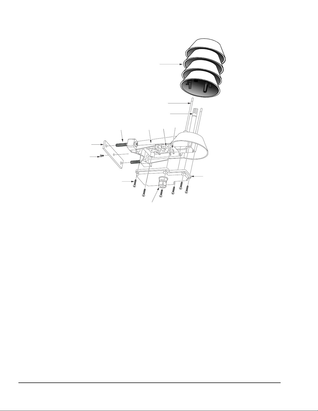
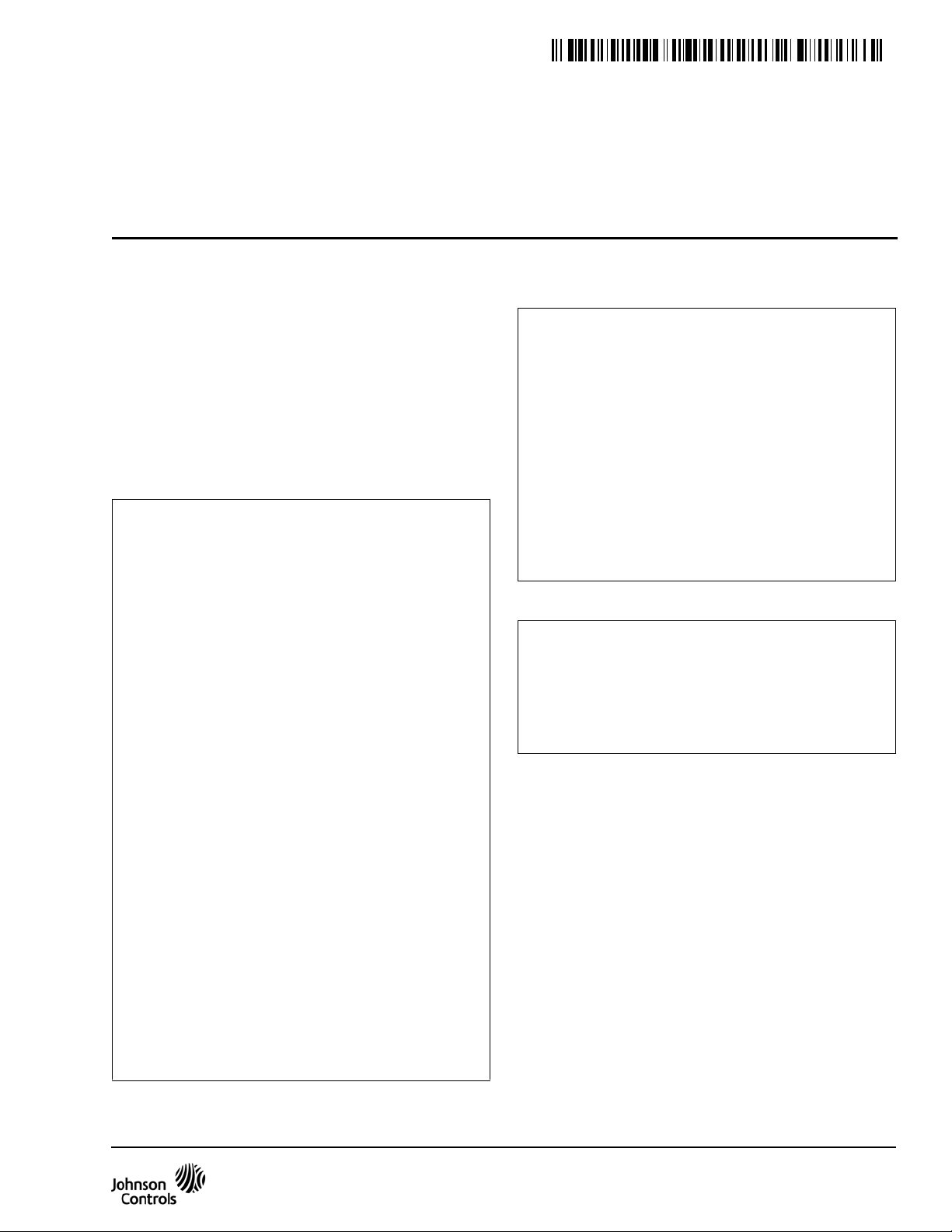
Figure 1: Hx-68P3 Series Outside Humidity and Temperature Transmitter Features
FIG:Features
Radiation Shield
Radiation Shield Screws
Humidity Sensor and Temperature Sensor
(Under PTFE Membrane Filt er)
Transmi tter
Body
Screw
Te rm i na l
DIP
Switches
Pole Mounting
Screw
Pole
Mounting
Clamp
Set Screw
Cable Gland
Transmitter
Cover
Transmi tter
Cover Screw (Captured)
Installation
Parts Included
• relative humidity and temperature transmitter with
• conduit adaptor
• weather shield
• pole mounting clamp with screws (wall mount
• installation instructions
Tools Needed
• medium Phillips screwdriver
• small slotted screwdriver
cable gland
screws and anchors not included)
Hx-68P3 Series Outside Humidity and Temperature Transmitters Installation Instructions2
• wire cutters
• open-ended wrench
• zip ties
• cable clips
Page 3
Dimensions
Figure 2: Hx-68P3 Series Outside Humidity and Temperature Transmitter Dimensions, in. (mm)
4-7/8 (122)
10-3/8 (264)
FIG:Dimensio ns
Cable Gland Suitable for
5/32 to 5/16 (4 to 8) Cable
Diameter 3/32 to 2-11/32 (25 to 60)
Diameter 7/32 (6)
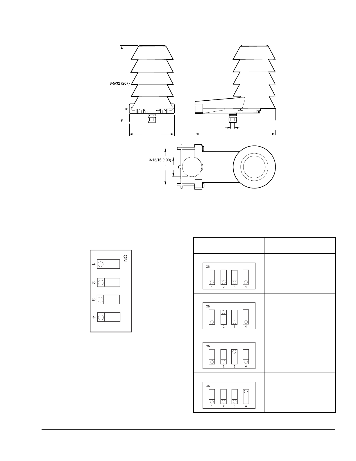
Figure 3: DIP Switch Positions
Non-Metric
Td
h
Tw
Metric
RH
RH
RH
DIP Switch Settings
The DIP switches on the component board control the
humidity output parameter and scaling. Figure 3 shows
the default DIP switch settings.
Change the position of the DIP switches to the desired
setting.
Table 1: DIP Switch Positions for Metric Output
DIP Switch Position Analog Output
Parameter and Scaling
Relative Humidity (RH)
0 to 100%
Temperature (T)
-40 to 60C
Dewpoint (Td)
-40 to 60C
Temperature (T)
-40 to 60C
Enthalpy (h)
-40 to 460kJ/kg
Temperature (T)
-40 to 60C
Wet Bulb Temperature (Tw)
-40 to 60C
Temperature (T)
-40 to 60C
Hx-68P3 Series Outside Humidity and Temperature Transmitters Installation Instructions 3
Page 4

Table 2: DIP Switch Positions for Non-Metric
Figure 4: Conduit Adaptor
FIG:NAAdaptor
Adaptor
Nut
!
Figure 5: Preparing the Transmitter for Mounting
FIG:Terminal
Cable Gland
(Shown)
Screw
Terminal
Output
DIP Switch Position Analog Output
Parameter and Scaling
Relative Humidity (RH)
0 to 100%
4. Manually tighten the adaptor into the nut, turning in
a clockwise direction.
5. Tighten the adaptor onto the adaptor body, turning
in a clockwise direction.
Mounting
Temperature (T)
-40 to 140F
Dewpoint (Td)
-40 to 140F
Temperature (T)
-40 to 140F
Enthalpy (h)
-10 to 190 BTU/lb
Temperature (T)
-40 to 140F
Wet Bulb Temperature (Tw)
-40 to 140F
Temperature (T)
-40 to 140F
Installing the Conduit Adaptor - Optional
Using the conduit adaptor is optional. If you do not use
the conduit adaptor, proceed to Mounting
.
CAUTION: Risk of Electric Shock.
Disconnect the power supply before
making electrical connections to avoid
electric shock.
MISE EN GARDE : Risque de décharge
électrique.
Débrancher l'alimentation avant de
réaliser tout raccordement électrique afin
d'éviter tout risque de décharge
électrique.
Location Considerations
• Install the transmitter in a place that receives
minimal direct sunlight.
• Avoid placing the transmitter near windows, air
conditioning units, or other heat and moisture
sources such as cooling towers.
• Install the transmitter at least 8 ft (2.5 m) above the
ground.
IMPORTANT: To minimize the time spent working
on a ladder, prepare the transmitter configuration
and wiring before mounting the transmitter.
To install the conduit adaptor, follow these steps.
1. Loosen the six captive screws that hold the
transmitter cover in place. See Figure 5.
2. Unscrew the cable gland from the transmitter
cover. See Figure 1 for the location of the cable
gland.
3. Align the nut with the opening inside the transmitter
cover, and insert the adaptor body into the
transmitter conduit opening.
1. Loosen the six captive screws that hold the
transmitter cover in place.
2. Be sure the DIP switches are set to the desired
setting. See DIP Switch Settings
.
Hx-68P3 Series Outside Humidity and Temperature Transmitters Installation Instructions4
Page 5

3. Route the power and signal cable through the
Figure 6: Pole Installation
FIG:Pole
Figure 7: Securing Cable to a Pole
FIG:Cable Pole
Figure 8: Wall Installation, in. (mm)
3-15/16 (100)
Diameter 7/ 32 (6)
FIG:Wall
cable gland or the conduit adaptor to the screw
terminals, and connect the wires.
4. Disconnect the terminal block by pulling it away
from the component board.
5. Adjust the cable length between the cable gland
and the terminal block. Make sure the cover closes
without leaving a loop within the transmitter.
6. Tighten the cable gland or conduit adaptor.
IMPORTANT: Do not attach the cover to the
transmitter until the transmitter has been mounted
on the pole or wall.
Pole Mounting
IMPORTANT: We recommend a pole diameter of
2-11/32 to 3-3/32 in. (25 to 60 mm) if you use the
supplied clamp and screws.
5. Secure the cable to the pole using cable ties.
Incorporate a drip loop below the cable gland to
prevent water from running into the transmitter
along the cable.
To mount the Hx-68P3 Series Outside Humidity and
Temperature Transmitter to a pole:
1. Attach the clamp to the pole with the set screw.
See Figure 6.
2. Align the transmitter mounting bracket with the
holes on the clamp, and insert the screws through
the holes of the transmitter mounting bracket and
into the clamp.
3. Tighten the screws securing the transmitter
assembly onto the pole.
4. Plug in the screw terminal block (terminal screws
facing the transmitter cover), close the cover, and
tighten the cover screws. See Figure 5 for plugging
in the terminal block and attaching the cover.
Wall Mounting
To mount the Hx-68P3 Series Outside Humidity and
Temperature Transmitter to a wall:
1. Drill two holes for the wall plugs 3-15/16 in.
(100 mm) apart.
2. Insert the anchors into the holes.
3. Align the transmitter up to the holes, and insert the
screws through the holes and into the anchors.
4. Tighten the screws securing the transmitter onto
the wall.
5. Plug in the screw terminal block (terminal screws
facing the transmitter cover), close the cover, and
tighten the cover screws. See Figure 5 for plugging
in the terminal block and attaching the cover.
Hx-68P3 Series Outside Humidity and Temperature Transmitters Installation Instructions 5
Page 6

6. Secure the cable to the wall using cable ties.
!
Figure 9: Securing Cable on a Wall
FIG:Cable Wall
Figure 10: HT-68P3-0N000 Wiring
Two 4 to 20 mA outputs,
temperature output scaling -40
to 140°F (-40 to 60°C)
Alternate wiring with one
power supply.
1
2
3
4
mA
mA
mA
mA
HUM+
HUMT+
T-
HUM+
HUMT+
T-
+
+
+
Ω
Ω
1
2
3
4
FIG:HT-6803-0N00
Figure 11: HE-68P3-0N000 Wiring
1
2
3
4
5
VDC+/AC
VDC-/AC
T+
T-/
HUM+
HUM-
+
+
Ω
V
1
2
3
4
5
1
2
3
4
5
1
2
3
4
5
V
V
V
VDC+/AC
VDC-/AC
T+
T-/
HUM+
HUM-
Ω
Two 0 to 10 V outputs,
temperature output scaling
-40 to 140°F (-40 to 60°C)
Terminals 2 and 5 are
internally connected on the
transmitter, so you can use
a cable with four wires.
Incorporate a drip loop below the cable gland to
prevent water from running into the transmitter
along the cable.
Wiring
CAUTION: Risk of Electric Shock.
Disconnect the power supply before
making electrical connections to avoid
electric shock.
MISE EN GARDE : Risque de décharge
électrique.
Débrancher l'alimentation avant de
réaliser tout raccordement électrique afin
d'éviter tout risque de décharge
électrique.
Calibration
There are no calibration adjustments to make for this
device.
T roubleshooting
Analog Output Error State
The output channel is in a defined error level instead of
the measured result in two situations.
• The transmitter detects a measurement
malfunction such as a damaged sensor or
unfavorable environmental conditions.
• The measured values are outside of the scaled
output range. See Analog Output Overrange
Behavior.
The error level depends on the output type.
• For a 0 to 10 V output, the error level is 11 V.
• For a 4 to 20 mA output, the error level is 3.6 mA.
The transmitter resumes normal operation of the
analog outputs when the cause of the error state is
removed.
Hx-68P3 Series Outside Humidity and Temperature Transmitters Installation Instructions6
Analog Output Overrange Behavior
The Analog outputs have a defined behavior when the
values measure by the transmitter are outside the
scaled analog output range.
• The output is clipped at the end of the range.
• The output is set to the error state when the
measured value is 5% outside of the scaled range.
• The output resumes normal function when the
measured value is back on the scaled range.
Repair Information
If the Hx-68P3 Series Outside Humidity and
Temperature Transmitter fails to operate within its
specifications, replace the unit. For a replacement
transmitter, contact the nearest Johnson Controls®
representative.
Page 7

Technical Specifications
Hx-68P3 Series Outside Humidity and Temperature Transmitters (Part 1 of 2)
Operating Conditions T emperature
Humidity 0 to 100% RH
Relative Humidity Measurement range 0 to 100% RH
Accuracy: Temperature Range
50 to 86F (10 to 30C):
0 to 90% RH
90 to 100% RH
Accuracy: Temperature Range
-4 to 50F (-20 to 10C)
86 to 140F (30 to 60C):
0 to 90% RH
90 to 100% RH
Accuracy: Temperature Range
-40 to -4F (-40 to -20C):
0 to 100% RH ±7% RH
Stability in typical HVAC app. ±2% RH over 2 years
Temperature Measurement range
Accuracy at 68F (20C) ±0.54F (±0.3C)
Temperature dependance ±0.01C/C
Temperature sensor Pt1000 RTD Class F0.1 IEC60751
Dewpoint Accuracy at 68F (20C) and
Wet Bulb ±1.3F (±0.7C)
Enthalpy ±0.9 BTU/lb (±2kj/kg)
Ingress Protection IP65
Maximum Wind/Flow Speed 98.42 ft/s (30 m/s)
Storage Temperature
Current Output
(HT-68P3-0N000) (Two-Wire)
Voltage Output (HE-68P30N000) (Three-Wire)
Wire Size
80% RH
Outputs 4 to 20 mA, loop powered
Loop resistance 0 to 600 ohm
Supply voltage 20 to 28 VDC at 600 ohm load;
Outputs 0 to 10 V
Load resistance 10k ohm minimum
Supply voltage 18 to 35 VDC; 24 VAC ±20%, 50/60 Hz
-40 to 140F (-40 to 60C)
±3% RH
±5% RH
±5% RH
±7% RH
-40 to 140F (-40 to 60C)
±1.6F (±0.9C)
-40 to 140F (-40 to 60C)
10 to 28 VDC at 0 ohm load
2
16 AWG (1.5 mm
) maximum
Hx-68P3 Series Outside Humidity and Temperature Transmitters Installation Instructions 7
Page 8

Metasys® and Johnson Controls® are registered trademarks of Johnson Controls, Inc.
All other marks herein are the marks of their respective owners. © 2016 Johnson Controls, Inc.
Building Efficiency
507 E. Michigan Street, Milwaukee, WI 53202
Hx-68P3 Series Outside Humidity and Temperature Transmitters (Part 2 of 2)
Electromagnetic Compliance EN61326-1 Industrial Environment
Standard Housing Color White (RAL9003)
Compliance United States FCC compliant to CFR 47, Part 15, Subpart B,
Class A
Canada Under CAN/CSA-CEI/IEC CISPR 22:02, Class A
Europe CE Mark - Johnson Controls, Inc. declares that this
product is in compliance with the essential
requirements and other relevant provisions of the
EMC Directive.
Australia and New Zealand RCM Mark, Australia/NZ Emissions Compliant
The performance specifications are nominal and conform to acceptable industry standard. For application at conditions beyond these
specifications, consult the local Johnson Controls office. Johnson Controls, Inc. shall not be liable for damages resulting from misapplication or
misuse of its products.
European Single Point of Contact: NA/SA Single Point of Contact: APAC Single Point of Contact:
JOHNSON CONTROLS
WESTENDHOF 3
45143 ESSEN
GERMANY
JOHNSON CONTROLS
507 E MICHIGAN ST
MILWAUKEE WI 53202
USA
JOHNSON CONTROLS
C/O CONTROLS PRODUCT MANAGEMENT
NO. 22 BLOCK D NEW DISTRICT
WUXI JIANGSU PROVINCE 214142
CHINA
Hx-68P3 Series Outside Humidity and Temperature Transmitters Installation Instructions8
Published in U.S.A. www.johnsoncontrols.com
 Loading...