

Johnson Controls HVAHR168B32S, HVAHR096B32S, HVAHR120B32S, HVAHR144B32S, HVAHR192B32S Installation And Maintenance Manual
...
Installation
and
Maintenance
Manual
INVERTER-DRIVEN
MULTI-SPLIT SYSTEM
HEAT RECOVERY
AIR CONDITIONERS
Models:
Outdoor Units;
208/230V
(H,Y)VAHR072B32S, (H,Y)VAHR096B32S,
(H,Y)VAHR120B32S, (H,Y)VAHR144B32S,
(H,Y)VAHR168B32S, (H,Y)VAHR192B32S,
(H,Y)VAHR216B32S, (H,Y)VAHR240B32S,
(H,Y)VAHR264B32S, (H,Y)VAHR288B32S,
(H,Y)VAHR312B32S, (H,Y)VAHR336B32S,
(H,Y)VAHR360B32S, (H,Y)VAHR384B32S,
(H,Y)VAHR408B32S, (H,Y)VAHR432B32S
460V
(H,Y)VAHR072B42S, (H,Y)VAHR096B42S,
(H,Y)VAHR120B42S, (H,Y)VAHR144B42S,
(H,Y)VAHR168B42S, (H,Y)VAHR192B42S,
(H,Y)VAHR216B42S, (H,Y)VAHR240B42S,
(H,Y)VAHR264B42S, (H,Y)VAHR288B42S,
(H,Y)VAHR312B42S, (H,Y)VAHR336B42S,
(H,Y)VAHR360B42S, (H,Y)VAHR384B42S,
(H,Y)VAHR408B42S, (H,Y)VAHR432B42S
IMPORTANT:
READ AND UNDERSTAND
THIS MANUAL BEFORE
INSTALLING THIS HEAT
RECOVERY AIR CONDITIONER.
KEEP THIS MANUAL FOR
FUTURE REFERENCE.
P5417009

Important Notice
● Johnson Controls Inc. pursues a policy of continuing improvement in design and performance in its products.
As such, Johnson Controls Inc. reserves the right to make changes at any time without prior notice.
● Johnson Controls Inc. cannot anticipate every possible circumstance that might involve a potential hazard.
● This heat recovery air conditioning unit is designed for standard air conditioning applications only.
Do not use this unit for anything other than the purposes for which it was intended for.
● The installer and system specialist shall safeguard against leakage in accordance with local codes.
No part of this manual may be reproduced in any way without the expressed written consent of Johnson
Controls Inc.
● This heat recovery air conditioning unit will be operated and serviced in the United States of America and
comes with a full complement of the appropriate Safety, Danger, and Caution, Warnings.
● If you have questions, please contact your distributor or contractor.
● This manual provides common descriptions, basic and advanced information to maintain and service this
heat recovery air conditioning unit which you operate as well for other models.
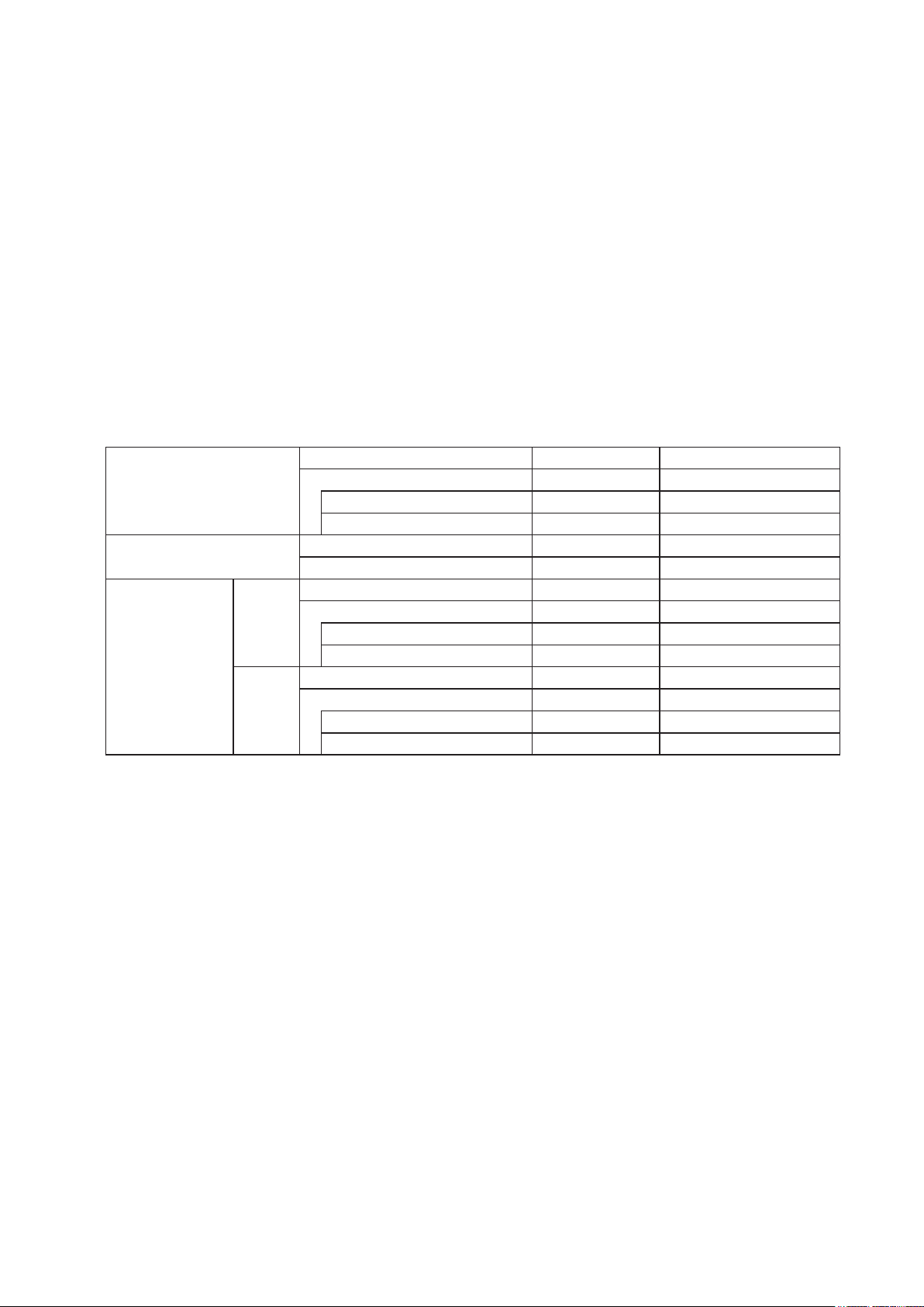
● This heat recovery air conditioning unit has been designed for a specic temperature range. For optimum
performance and long life, operate this unit within the range limits according to the table below.
Temperature
o
F WB (oC WB) 59 (15) ~ 73 (23)
F DB (oC DB) 23 (-5) ~ 122 (50)
F DB (oC DB) 14 (-10) ~ 109 (43)
F DB (oC DB) -10 (-23) ~ 109 (43)
o
F DB (oC DB) 59 (15) ~ 80 (27)
F WB (oC WB) -13 (-25) ~ 59 (15)
o
F WB (oC WB) 59 (15) ~ 73 (23)
F DB (oC DB) 23 (-5) ~ 75 (24)
F DB (oC DB) 14 (-10) ~ 75 (24)
F DB (oC DB) -10 (-23) ~ 75 (24)
o
F DB (oC DB) 59 (15) ~ 80 (27)
F WB (oC WB) 22 (-6) ~ 59 (15)
F WB (oC WB) 12 (-11) ~ 59 (15)
F WB (oC WB) -11 (-24) ~ 59 (15)
Cooling Operation Range
Heating Operation Range
Cooling
Cooling & Heating
Operation Range
Heating
DB: Dry Bulb, WB: Wet Bulb
Indoor
Outdoor
1, 2, 3, 6, 10 o
with Snow Protection Hood
with Low Ambient Kit
Indoor
Outdoor
7, 8, 9 o
Indoor
Outdoor
1, 2, 3, 6, 10 o
with Snow Protection Hood
with Low Ambient Kit
Indoor
Outdoor
7, 10 o
with Snow Protection Hood
with Low Ambient Kit
4, 6 o
5, 6, 8 o
4, 6 o
5, 6, 8 o
4, 6 o
5, 6, 8 o
P5417009-rev.6
i

1. When the system meets the following conditions, the outdoor unit may be thermo-OFF to prevent the compressor
from failure.
●
Total capacity of the operating indoor unit is larger than capacity of outdoor unit; and
●
Outdoor air temperature is 100oF DB (38oC DB) or more.
2. If the installation takes place under either one of the following conditions, the maximum connectable indoor unit
capacity ratio is 100%.
●
Outdoor air temperature is 109oF (43oC) or more during cooling operation; or
●
Outdoor air temperature is 14oF (-10oC) or less during cooling operation.
3. When installing the snow protection hood or low ambient kit, the upper limit of outdoor air temperature must be 109
o
C).
(43
4. When the outdoor air temperature is 23
o
F (-5oC) or less during the outdoor unit cooling operation, the minimum
connectable indoor unit capacity is 18MBH.
In this case, installing the snow protection hood (optional part) is required.
o
5. When the outdoor air temperature is 14
F (-10oC) or less during the outdoor unit cooling operation, the minimum
connectable indoor unit capacity is 18MBH.
In this case, installing the Low Ambient Kit (optional part) is required.
6. When operating the outdoor unit under the low cooling load conditions and in the low outdoor air temperature, (approx.
o
F DB (10oC DB) or less), the indoor unit will be Thermo-OFF to prevent the heat exchanger of the indoor unit from
50
frost.
Depending on the operating condition, the outlet air temperature of the indoor unit may be excessively low.
Pay attention to the direction of the outlet air. Do not place items near the air outlet and under the indoor unit as they
may be damaged by condensates that may form if the humidity or the latent heat load is continuously high.
●
(for example:
7. When operating the outdoor unit under the low heating load conditions and the outdoor temperature is
o
F DB (15oC DB) or more, the outdoor unit will be Thermo-OFF to protect the compressor from failure.
59
8. Operation in the outdoor temperature of 5~-13
using at kitchen or gymnasium; or
●
using at the room that has high population density or introduces outside air; or
●
using humidier together; or
●
using combustion heater like gas heater together)
o
F WB (-15~-25oC WB) is assumed to limited conditions such as start-
up in early morning. Extended operation in this condition may shorten the life of the compressor.
o
9. When the outdoor air temperature is 14
F (-10oC) or less, or under the high heating load conditions, the total indoor
unit capacity should be less than 100% of the outdoor unit capacity, and the total piping length should be less than
984 ft (300m).
10. There are some limitations of the Height Difference between Outdoor Units and Indoor Units.
Refer to Section 6.5 “Piping Size and Multi-kit Selection”, for details.
o
F
● This manual should be considered as a permanent part of the air conditioning equipment and should
remain with the air conditioning equipment.
Product Inspection upon Arrival
1. Upon receiving this product, inspect it for any damages incurred in transit. Claims for damage, either
apparent or concealed, should be led immediately with the shipping company.
2. Check the model number, electrical characteristics (power supply, voltage, and frequency rating), and
any accessories to determine if they agree with the purchase order.
3. The standard utilization for this unit is explained in these instructions. Use of this equipment for
purposes other than what it designed for is not recommended.
4. Please contact your local agent or contractor as any issues involving installation, performance, or
maintenance arise. Liability does not cover defects originating from unauthorized modications
performed by a customer without the written consent of Johnson Controls, Inc. Performing any
mechanical alterations on this product without the consent of the manufacturer will render your warranty
null and void.
ii
P5417009-rev.6
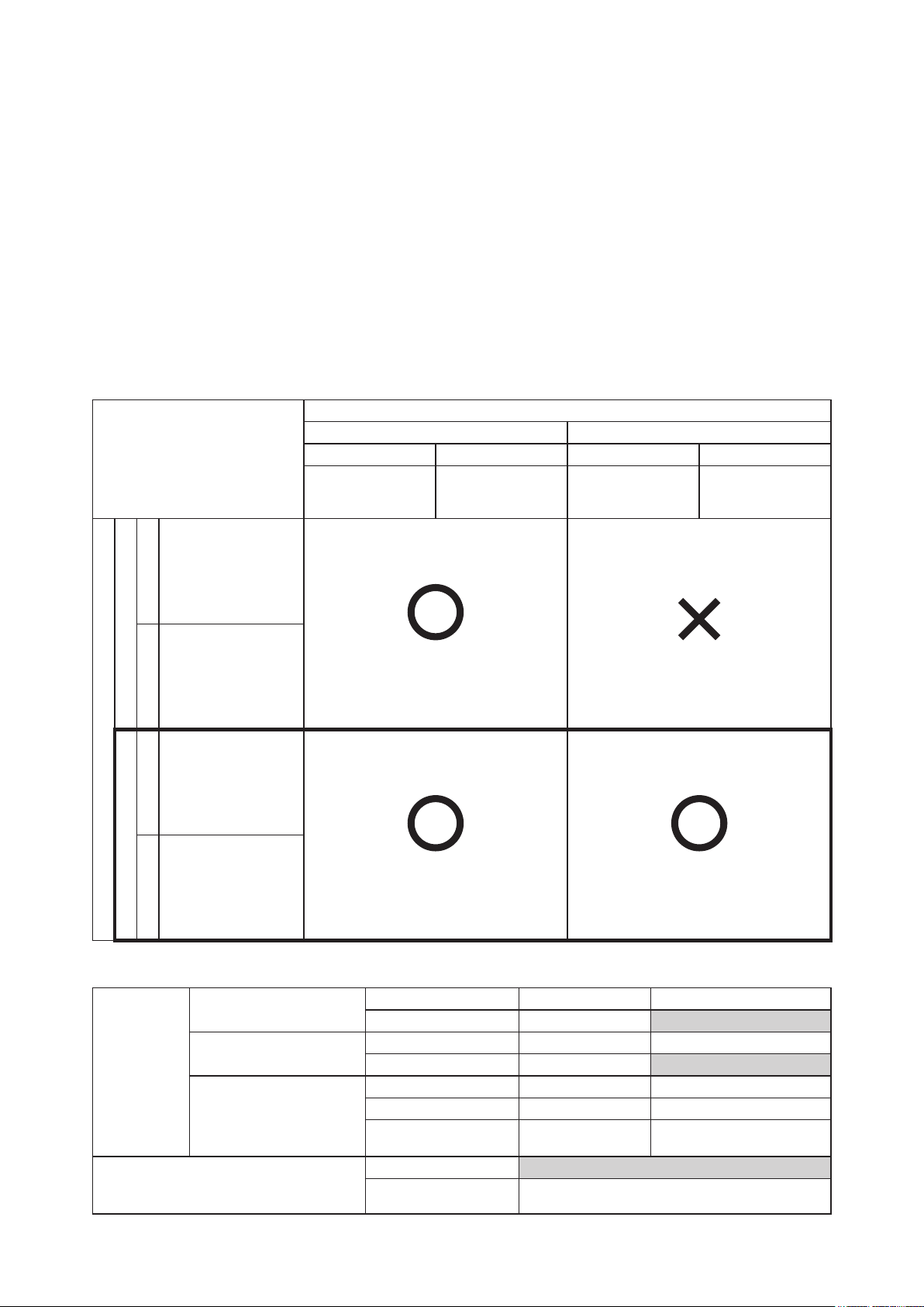
Interchangeability between Generation 1 and 2 Change-Over Boxes
● Generation 2 change-over box is compatible with the generation 2 outdoor unit.
● Generation 1 change-over box is compatible with the generation 1 outdoor unit when there is no
generation 2 change-over box in the same system.
● Generation 1 change-over box is compatible with the generation 2 outdoor unit with limitations of the
operating temperature range and the connectable indoor unit capacity ratio.
See the following table “Limitations for Combination of Generation 1 Change-Over Box and Generation 2
Outdoor Unit” for details.
● Generation 1 and 2 change-over boxes can not be used in the same system together.
● Production of generation 1 change-over box shall be discontinued. However, it will be supplied for
servicing and maintenance until further notice. Regarding order requests for the generation 1 changeover box, contact Tech Support at: 1-844-873-4445 (option 2).
Determining Propriety of Connection between
Change-Over Box and VRF Outdoor Unit (Heat Recovery)
Change-Over Box
Generation 1 Generation 2
Model of Change-Over Box
and VRF Outdoor Unit
Single Branch Type Multiple Branch Type Single Branch Type Multiple Branch Type
COBS048B21S
COBS096B21S
-
COBS048B22S
COBS096B22S
COB04M132B22S
COB08M264B22S
COB12M264B22S
(H,Y)VAHR072B31S
(H,Y)VAHR096B31S
(H,Y)VAHR120B31S
208/230V Type
(H,Y)VAHR072B41S
Generation 1
(H,Y)VAHR096B41S
(H,Y)VAHR120B41S
460 Type
(H,Y)VAHR072B32S
(H,Y)VAHR096B32S
(H,Y)VAHR120B32S
(H,Y)VAHR144B32S
(H,Y)VAHR168B32S
208/230V Type
(H,Y)VAHR192B32S
VRF Outdoor Unit (Heat Recovery)
(H,Y)VAHR072B42S
(H,Y)VAHR096B42S
(H,Y)VAHR120B42S
(H,Y)VAHR144B42S
(H,Y)VAHR168B42S
460V Type
Generation 2 (This Manual)
(H,Y)VAHR192B42S
Available Not Available
Available Available
Limitations for Combination of Generation 1 Change-Over Box and Generation 2 Outdoor Unit
Cooling Operation Range
Heating Operation Range
Temperature
Cooling & Heating
Operation Range
Connectable Indoor Unit Capacity Ratio
DB: Dry Bulb, WB: Wet Bulb
Indoor °F WB (°C WB) 59 (15) ~ 73 (23)
Outdoor °F DB (°C DB) 23 (-5) ~ 109 (43)
Indoor °F DB (°C DB) 59 (15) ~ 80 (27)
Outdoor °F WB (°C WB) -4 (-20) ~ 59 (15)
Indoor (Cooling Side) °F WB (°C WB) 59 (15) ~ 73 (23)
Indoor (Heating Side) °F DB (°C DB) 59 (15) ~ 80 (27)
Outdoor
°F DB (°C DB) 23 (-5) ~ 75 (24)
°F WB (°C WB) 22 (-6) ~ 59 (15)
Maximum 100%
Minimum
Depending on Outdoor Units
(Refer to Table 3.2 for details.)
P5417009-rev.6
iii

TABLE OF CONTENTS
1. Introduction ........................................................................................................................................................... 1
2. Important Safety Instructions ................................................................................................................................ 1
3. Before Installation ................................................................................................................................................. 6
3.1 Factory-Supplied Accessories ...................................................................................................................... 6
3.2 Necessary Tools and Instrument List for Installation .................................................................................... 7
3.3 Flaring and Joint ........................................................................................................................................... 9
3.4 Line-Up of Outdoor Units .............................................................................................................................11
3.5 Combinations of Indoor Units and Outdoor Units ....................................................................................... 12
3.6 Caution about Outdoor Unit Installation ..................................................................................................... 14
3.7 Piping Work between Outdoor Units .......................................................................................................... 14
4. Outdoor Unit Installation ..................................................................................................................................... 15
4.1 Installation Location and Precautions ......................................................................................................... 15
4.2 Service Space ............................................................................................................................................ 16
5. Transportation and Installation Work .................................................................................................................. 19
5.1 Transportation ............................................................................................................................................ 19
5.2 Handling of Outdoor Unit ............................................................................................................................ 22
5.3 Installation Work ......................................................................................................................................... 22
5.3.1 Concrete Foundations ...................................................................................................................... 22
5.3.2 Condensate Treatment ..................................................................................................................... 24
6. Refrigerant Piping Work ...................................................................................................................................... 26
6.1 Piping Materials .......................................................................................................................................... 27
6.2 Piping Connection Work ............................................................................................................................. 30
6.2.1 Stop Valve ........................................................................................................................................ 30
6.2.2 Piping Connection Method ................................................................................................................ 32
6.3 Piping Work between Outdoor Units .......................................................................................................... 35
6.4 Piping Sizes between Outdoor Units .......................................................................................................... 38
6.5 Piping Size and Multi-Kit Selection ............................................................................................................. 40
6.6 Multi-Kit Connection ................................................................................................................................... 51
7. Electrical Wiring .................................................................................................................................................. 52
7.1 General Check ........................................................................................................................................... 53
7.2 Electrical Wiring Connection ...................................................................................................................... 54
7.3 Electrical Wiring for Outdoor Unit ............................................................................................................... 57
7.4 Electrical Wiring Connections of Indoor Unit, Outdoor Unit, and Change-Over Box .................................. 59
7.5 DIP Switch Setting of Outdoor Unit ............................................................................................................ 62
8. Additional Refrigerant Charge ............................................................................................................................. 66
8.1 Airtight Test ................................................................................................................................................. 66
8.2 Vacuuming .................................................................................................................................................. 68
8.3 Charging Work ........................................................................................................................................... 69
8.4 Additional Refrigerant Charge Calculation ................................................................................................. 71
9. Test Run .............................................................................................................................................................. 73
9.1 Before Test Run .......................................................................................................................................... 73
9.2 Test Run ..................................................................................................................................................... 74
10. Safety and Control Device Setting ...................................................................................................................... 81
iv
P5417009-rev.6

1. Introduction
This manual concentrates on the Outdoor Heat Recovery Unit. Read this manual carefully before installation.
Read over the installation manual for the Indoor Unit also.
This manual should be considered as a permanent part of the air conditioning equipment and should
remain with the air conditioning equipment.
(Transportation/Installation Work) > (Refrigerant Piping Work) > (Electrical Wiring Work) > (Ref. Charge Work) > (Test
Run) > (User)
2. Important Safety Instructions
Signal Words
Indicates a hazardous situation that, if not avoided, could result in death or
serious injury.
Indicates a hazardous situation that, if not avoided, could result in minor or
moderate injury.
Indicates information considered important, but not hazard-related (for
example, messages relating to property damage).
General Precautions
To reduce the risk of serious injury or death, read these instructions thoroughly
and follow all warnings or cautions included in all manuals that accompanied
the product and are attached to the unit. Refer back to these safety
instructions as needed.
● This system should be installed by personnel certied by Johnson Controls, Inc. Personnel must be
qualied according to local codes and regulations. Incorrect installation could cause leaks, electric
shock, re or explosion. In areas where Seismic ‘’Performance requirements are specied, the
appropriate measures should be taken during installation to guard against possible damage or injury
that might occur in an earthquake if the unit is not installed correctly, injuries may occur due to a falling
unit.
● Use appropriate Personal Protective Equipment (PPE), such as gloves and protective goggles and,
where appropriate, have a gas mask nearby. Also use electrical protection equipment and tools suited
for electrical operation purposes. Keep heat shields, re blankets, and a re extinguisher nearby during
brazing. Use care in handling, rigging, and setting of bulky equipment.
● When transporting, be careful when picking up, moving and mounting these units. Although the unit may
be packed using plastic straps, do not use them for transporting the unit from one location to another. Do
not stand on or put any material on the unit. Get a partner to help, and bend with your knees when lifting
to reduce strain on your back. Sharp edges or thin aluminum ns on the air conditioner can cut ngers,
so wear protective gloves.
● Do not touch or adjust any safety devices inside the indoor or outdoor units. All safety features,
disengagement, and interlocks must be in place and functioning correctly before the equipment is put
into operation. If these devices are improperly adjusted or tampered with in any way, a serious accident
can occur. Never bypass or jump-out any safety device or switch.
● Johnson Controls will not assume any liability for injuries or damage caused by not following steps
outlined or described in this manual. Unauthorized modications to Johnson Controls products are
prohibited as they…
◦ May create hazards which could result in death, serious injury, equipment damage, or property
damage;
◦ Will void product warranties;
◦ May invalidate product regulatory certications;
◦ May violate OSHA standards;
P5417009-rev.6
1

Take the following precautions to reduce the risk of property damage.
● Be careful that moisture, dust, or variant refrigerant compounds not enter the refrigerant cycle during
installation work. Foreign matter could damage internal components or cause blockages.
● If air lters are required on this unit, do not operate the unit without the air lter set in place. If the air
lter is not installed, dust may accumulate and breakdown may result.
● Do not install this unit in any place where silicon gases can coalesce. If the silicon gas molecules
attach themselves to the surface of the heat exchanger, the nned surfaces will repel water. As a
result, any amount of drainage moisture condensate can overow from the drain condensate pan and
could run inside of the electrical box, possibly causing electrical failures.
● When installing the unit in a hospital or other facility where electromagnetic waves are generated
from nearby medical and/or electronic devices, be prepared for noise and electronic interference
Electromagnetic Interference (EMI). Do not install where the waves can directly radiate into the
electrical box, controller cable, or controller. Inverters, appliances, high-frequency medical equipment,
and radio communications equipment may cause the unit to malfunction. The operation of the unit
may also adversely affect these same devices. Install the unit at least 10 ft. (approximately 3m) away
from such devices.
● When a wireless controller is used, locate at a distance of at least 3.3 ft. (approximately 1m) between
the indoor unit and electric lighting. If not, the receiver part of the unit may have difculty receiving
operation commands.
● Do not install the unit in any location where animals and plants can come into direct contact with the
outlet air stream. Exposure could adversely affect the animals and plants.
● Do not install the unit with any downward slope to the side of the drain adaptor. If you do, you may
have drain water owing back which may cause leaks.
● Be sure the drain hose discharges water properly. If connected incorrectly, it may cause leaks.
● Do not install the unit in any place where oil can seep onto the units, such as table or seating areas in
restaurants, and so forth. For these locations or social venues, use specialized units with oil-resistant
features built into them. In addition, use a specialized ceiling fan designed for restaurant use. These
specialized oil-resistant units can be ordered for such applications. However, in places where large
quantities of oil can splash onto the unit, such as a factory, even the specialized units cannot be used.
These products should not be installed in such locations.
Installation Precautions
To reduce the risk of serious injury or death, the following installation
precautions must be followed.
● When installing the unit into…
▫ A wall: Make sure the wall is strong enough to hold the unit’s weight. It may be necessary to
construct a strong wood or metal frame to provide added support.
▫ A room: Properly insulate any refrigerant tubing run inside a room to prevent “sweating” that can
cause dripping and water damage to walls, oors, or property within the space.
▫ Damp or uneven areas: Use a raised concrete pad or concrete blocks to provide a solid, level
foundation for the unit to prevent water damage and abnormal vibration.
▫ An area with high winds: Securely anchor the outdoor unit down with bolts and a metal frame.
Provide a suitable wind bafe.
▫ A snowy area: Install the outdoor unit on a raised platform that is higher than anticipated snow
levels and drifting snow. Provide snow protection hood or low ambient kit.
● Do not install the unit in the following places. Doing so can result in an explosion, re, deformation,
corrosion, or product failure.
▫ Explosive or ammable atmosphere
▫ Where re, oil, steam, or powder can directly enter the unit, such as in close proximity or directly
above a kitchen stove.
▫ Where oil (including machinery oil) may be present.
▫ Where corrosive gases such as chlorine, bromine, or sulde can accumulate, such as near a hot
tub or hot spring.
▫ Where dense, salt-laden airow is heavy, such as in coastal regions.
▫ Where the air quality is of high acidity.
▫ Where harmful gases can be generated from decomposition.
2
P5417009-rev.6

● Do not position the drain pipe for the indoor unit near any sanitary sewers where corrosive gases
may be present. If you do, toxic gases can seep into breathable air spaces and can cause respiratory
injuries. If the drainpipe is installed incorrectly, water leakage and damage to the ceiling, oor,
furniture, or other possessions may result. If condensate piping becomes clogged, moisture can back
up and can drip from the indoor unit. Do not install the indoor unit where such dripping can cause
moisture damage or uneven locations: Use a raised concrete pad or concrete blocks to provide a
solid, level foundation for the unit to prevent water damage and abnormal vibration.
● Before performing any brazing work, be sure that there are no ammable materials or open ames
nearby.
● Perform a test run to ensure normal operation. Safety guards, shields, barriers, covers, and protective
devices must be in place while the compressor/unit is operating. During the test run, keep ngers and
clothing away from any moving parts.
● Clean up the site when nished, remembering to check that no tools, metal scraps, or bits of wiring
have been left inside the unit being installed.
● During transportation, do not allow the backrest of the forklift make contact with the unit, otherwise,
it may cause damage to the heat exchanger and also may cause injury when stopped or started
suddenly.
● Remove gas inside the closing pipe when the brazing work is performed. If the brazing ller metal is
melted with remaining gas inside, the pipes will be blown off and it may cause injury.
● Be sure to use nitrogen gas for an airtight test. If other gases such as oxygen gas, acetylene gas or
uorocarbon gas are accidentally used, it may cause explosion or gas intoxication.
After installation work for the system has been completed, explain the “Safety Precautions,” the proper use
and maintenance of the unit to the customer according to the information in all manuals that came with the
system. All manuals and warranty information must be given to the user or left near the Indoor Unit.
Refrigerant Precautions
To reduce the risk of serious injury or death, the following refrigerant
precautions must be followed.
● As originally manufactured, this unit contains refrigerant installed by Johnson Controls. Johnson
Controls uses only refrigerants that have been approved for use in the unit’s intended home country
or market. Johnson Controls distributors similarly are only authorized to provide refrigerants that
have been approved for use in the countries or markets they serve. The refrigerant used in this unit
is identied on the unit’s faceplate and/or in the associated manuals. Any additions of refrigerant into
this unit must comply with the country’s requirements with regard to refrigerant use and should be
obtained from Johnson Controls distributors. Use of any non-approved refrigerant substitutes will void
the warranty and will increase the potential risk of equipment damage, property damage, personal
injury, or death.
● Take measures to ensure that the refrigerant limitations in ASHRAE Standard 15 (Canada: B52), or
other local codes, are followed. If refrigerant gas has leaked during the installation work, ventilate the
room immediately.
● Check the design pressure for this product is 601 psi (4.15MPa). The pressure of the refrigerant
R410A is 1.4 times higher than that of the refrigerant R22. Therefore, the refrigerant piping for
R410A shall be thicker than that for R22. Make sure to use the specied refrigerant piping. If not, the
refrigerant piping may rupture due to an excessive refrigerant pressure. Besides, pay attention to
the piping thickness when using copper refrigerant piping. The thickness of copper refrigerant piping
differs depending on its material.
● The refrigerant R410A is adopted. The refrigerant oil tends to be affected by foreign matters such as
moisture, oxide lm, or other non-condensables. Perform the installation work with care to prevent
moisture, dust, or different refrigerant from entering the refrigerant cycle. Foreign matter can be
introduced into the cycle from such parts as expansion valve and the operation may be unavailable.
● To avoid the possibility of different refrigerant or refrigerant oil being introduced into the cycle, the
sizes of the charging connections have been changed from R407C type and R22 type. It is necessary
to prepare the following tools listed in Section 3 before performing the installation work.
● Use refrigerant pipes and joints which are approved for use with R410A.
● A compressor/unit comprises a pressurized system. Never loosen threaded joints while the system is
under pressure and never open pressurized system parts.
P5417009-rev.6
3

● Before installation is complete, make sure that the refrigerant leak test has been performed. If
refrigerant gases escape into the air, turn OFF the main switch, extinguish any open ames and
contact your service contractor. Refrigerant (Fluorocarbon) for this unit is odorless. If the refrigerant
should leak and come into contact with open ames, toxic gas could be generated. Also, because the
uorocarbons are heavier than air, they settle to the oor, which could cause asphyxiation.
● When installing the unit, and connecting refrigerant piping, keep all piping runs as short as possible,
and make sure to securely connect the refrigerant piping before the compressor starts operating. If
the refrigerant piping is not connected and the compressor activates with the stop valve opened, the
refrigerant cycle will become subjected to extremely high pressure, which can cause an explosion or
re.
● Tighten the are nut with a torque wrench in the specied manner. Do not apply excessive force to the
are nut when tightening. If you do, the are nut can crack and refrigerant leakage may occur.
● When maintaining, relocating, and disposing of the unit, dismantle the refrigerant piping after the
compressor stops.
● When pipes are removed out from under the piping cover, after the insulation work is completed,
cover the gap between the piping cover and pipes by a packing (eld-supplied). If the gap is not
covered, the unit may be damaged if snow, rain water or small animals enter the unit.
● Do not apply excessive force to the stop valve at the end of opening. Otherwise, the stop valve ies
out due to refrigerant pressure. At the test run, fully open the gas and liquid valves, otherwise, these
devices will be damaged. (It is closed before shipment.)
● If the arrangement for outdoor units is incorrect, it may cause owback of the refrigerant and result in
failure of the outdoor unit.
● The refrigerant system may be damaged if the slope of the piping connection kit exceeds +15
o
.
Electrical Precautions
Take the following precautions to reduce the risk of electric shock, re or
explosion resulting in serious injury or death.
● Highly dangerous electrical voltages are used in this system. Carefully refer to the wiring diagram and
these instructions when wiring. Improper connections and inadequate grounding can cause property
damage, serious injury, or death.
● Perform all electrical work in strict accordance with this manual and all the relevant regulatory
standards.
● Before servicing, open and tag all disconnect switches. Never assume electrical power is
disconnected. Check with meter and equipment.
● Only use electrical protection equipment and tools suited for this installation.
● Use specied cables between units.
● The new air conditioner may not function normally in the following instances:
▫ If electrical power for the new air conditioner is supplied from the same transformer as the
external equipment* referred to below.
▫ If the power supply cables for this external equipment* and the new air conditioner unit are
located in close proximity to each other.
External Equipment*: (Example): A lift, container crane, rectier for electric railway, inverter
power device, arc furnace, electric furnace, large-sized induction motor and large-sized switch.
Regarding the cases mentioned above, surge voltage may be inducted into the power supply
cables for the packaged air conditioner due to a rapid change in power consumption of the
device and an activation of a switch.
Check eld regulations and standards before performing electrical work in order to protect the
power supply for the new air conditioner unit.
● Communication cable shall be a minimum of AWG18 (0.82mm
2
), 2-Conductor, Stranded Copper.
Shielded cable must be considered for applications and routing in areas of high EMI and other
sources of potentially excessive electrical noise to reduce the potential for communication errors.
When shielded cable is applied, secure properly and terminate cable shield as required per Johnson
Controls guidelines. Plenum and riser ratings for communication cables must be considered per
application and local code requirements.
● Use an exclusive power supply for the air conditioner at the unit’s rated voltage.
4
P5417009-rev.6

● Be sure to install circuit breakers (ground fault interrupter, isolating switch, molded case circuit
breaker and so on), with the specied capacity. Ensure that the wiring terminals are tightened securely
to recommended torque specications.
● Clamp electrical wires securely with a cable clamp after all wiring is connected to the terminal block.
In addition, run wires securely through the wiring access channel.
● When installing the power lines, do not apply tension to the cables. Secure the suspended cables at
regular intervals, but not too tightly.
● Make sure that the terminals do not come into contact with the surface of the electrical box. If the
terminals are too close to the surface, it may lead to failures at the terminal connection.
● Turn OFF and disconnect the unit from the power supply when handling the service connector. Do not
open the service cover or access panel to the indoor or outdoor units without turning OFF the main
power supply.
● After ceasing operation, be sure to wait at least ve minutes before turning off the main power switch.
Otherwise, water leakage or electrical breakdown may result. Disconnect the power supply completely
before attempting any maintenance for electrical parts. Check to ensure that no residual voltage is
present after disconnecting the power supply.
● Do not clean with, or pour water into, the controller as it could cause electric shock and/or damage the
unit. Do not use strong detergent such as a solvent. Clean with a soft cloth.
● Check that the ground wire is securely connected. Do not connect ground wiring to gas piping, water
piping, lighting conductor, or telephone ground wiring.
● If a circuit breaker or fuse is frequently activated, shut down the system and contact your service
contractor.
● Perform all electrical work in accordance with this manual and in compliance with all regulations and
safety standards.
● Do not open a service access cover or panel of an indoor or outdoor unit without rst turning OFF the
power at the main power supply.
● Residual voltage can cause electric shock. At all times, check for residual voltage after disconnecting
from the power supply before starting work on the unit.
● This equipment can be installed with a Ground Fault Circuit Breaker (GFCI), which is a recognized
measure for added protection to a properly grounded unit. Install appropriate sized breakers / fuses
/ overcurrent protection switches, and wiring in accordance with local codes and requirements.
The equipment installer is responsible for understanding and abiding by applicable codes and
requirements.
P5417009-rev.6
5

3. Before Installation
3.1 Factory-Supplied Accessories
Check to ensure that the following accessories are packed with the outdoor unit.
Accessory 72 Model 96 Model 120 Model 144 Model 168 Model 192 Model Remarks
inch (mm)
Connection for
Refrigerant Gas
(High/Low) Pipe
Connection for
Refrigerant Gas
Accessory
Pipe
Cable Clamp
Cable Band
Screw
(One for Fixing Cable Clamp,
Two for Spare)
PVC Tube × 2 × 2 × 2 × 2 × 2 × 2 ID 1/2 (12)
(Low) Pipe
Connection
for Refrigerant
Liquid Pipe
90° Elbow for
Refrigerant Gas
Pipe
For Fixing
Power Supply
Wiring
For Fixing
Power Supply
Wiring
For Fixing
PVC Tube
ID 7/8 (22.2) →
OD 3/4 (19.05)
OD 3/8 (9.52) →
OD 1/2 (12.7)
x 1 x 1
ID 7/8 (22.2) →
OD 3/4 (19.05)
-
-
x 1 x 1 x 1 x 1 x 1 x 1
× 2 × 2 × 2 × 2 × 2 × 2
× 5 × 5 × 5 × 5 × 5 × 5
× 3 × 3 × 3 × 3 × 3 × 3
ID 1 (25.4) →
OD 7/8 (22.2)
x 1 x 1
ID 1 (25.4) →
OD 1 (25.4)
x 1 x 1 x 1
- -
x 1 x 1 x 1
- - - -
ID 1 (25.4) →
OD 1-1/8 (28.6)
ID 1 (25.4) →
OD 1 (25.4)
ID 1 (25.4) →
OD 1-1/8 (28.6)
OD 1/2 (12.7) →
OD 5/8 (15.88)
ID 1 (25.4) →
OD 1 (25.4)
- -
- -
- -
Rubber
Bush
Open/Close
Indication for
Stop Valve
Seismic Plate
Refrigerant Label
For
Communication
Cable
For Indication
of “Open”
× 2 × 2 × 2 × 2 × 2 × 2 OD 1-1/2 (38)
× 3 × 3 × 3 × 3 × 3 × 3
× 4 × 4 × 4 × 4 × 4 × 4
NOTICE
If any of these accessories are not packed with the unit, please contact your distributor.
6
P5417009-rev.6

3.2 Necessary Tools and Instrument List for Installation
No. Tool No. Tool No. Tool
1 Handsaw 8 Pliers 16 Wire Cutters
Phillips Screwdriver,
2
Slotted Screwdriver
3 Vacuum Pump 11 Hexagon Wrench 19 Crimper for Solderless Terminals
4 Refrigerant Gas Hose 12 Wrench 20 Hoist (for Indoor Unit)
5 Megohmmeter 13 Scale 21 Ammeter
6 Copper Pipe Bender 14 Charging Cylinder 22 Voltage Meter
7 Manual Water Pump (for Indoor Unit) 15 Gauge Manifold 23 Ratchet Wrench
Use specially designated tools for handling R410A refrigerant.
9 Copper Tube Cutter 17 Gas Leak Detector
10 Brazing Kit 18 Level
P5417009-rev.6
7

: Interchangeability is available with current R22
G
: Prohibited
5
Interchangeability
Measuring Instrument and Tool
with R22
R410A R407C
Copper Tube Cutter,
Chamfering Reamer
Flaring Tool
Extrusion
Adjustment Gauge
Pipe Bender
Expanding Tool
G G
G l G
l
G G
G G
Refrigerant
Pipe
l G
Torque Wrench
G G
Brazing Tool
Nitrogen Gas
Lubrication Oil
(for Flare Surface)
Refrigerant
Cylinder
Vacuum Pump
Adapter for
Vacuum Pump
Manifold Valve
G G
G G
l F
l F
G G H
S
l
l F
Vacuum
Drying
l
Refrigerant
Charge
Charging Hose
Charging Cylinder
Weight Scale
Refrigerant Gas
Leakage Detector
: Interchangeability with R407C.
S
l F
5 5
G G
S
l
: Only for Refrigerant R410A (No Interchangeability with R22)
l
: Only for Refrigerant R407C (No Interchangeability with R22)
F
Reason of Non-Interchangeability and Attention
(H: Strictly Required)
-
* The aring tools for R407C are applicable to R22.
* If using a aring tube, make the dimension of the
tube larger for R410A.
-
* For a hard temper pipe, aring is not available.
* For a hard temper pipe, bending is not available.
Cutting Pipe
Removing Burrs
Flaring for Tubes
Dimensional Control
for Extruded Portion
of Tube after Flaring
Bending
Use an elbow for bending and brazing.
* For a hard temper pipe, expansion of the tube is
Expanding Tubes
not available. Use socket for connecting tube.
* For 1/2 inch D. (12.7mm), 5/8 inch D. (15.88mm),
spanner size is up 1/16 inch (2mm).
Connection of
Flare Nut
* For 1/4 inch D. (6.35mm), 3/8 inch D. (9.52mm),
3/4 inch D. (19.05mm), spanner size is the same.
* Perform correct brazing work. Brazing for Tubes
* Strict Control against Contamination
(Blow nitrogen during brazing.)
Prevention from
Oxidation during
Brazing
* Use a synthetic oil which is equivalent to the oil
used in the refrigeration cycle.
Applying Oil to
the Flared Surface
* Synthetic oil absorbs moisture quickly.
* Check refrigerant cylinder color.
Liquid refrigerant charging is required for zeotropic
H
Refrigerant
Charging
refrigerant.
The current ones are applicable. However, it is
Vacuum Pumping
required to mount a vacuum pump adapter which
F
can prevent reverse ow when a vacuum pump
stops, resulting in no reverse oil ow.
* No interchangeability is available due to higher
pressures when compared with R22.
Use the same ones as for the current refrigerant.
H
Otherwise, mineral oil will ow into the cycle and
cause sludge resulting in clogging or compressor
Vacuum Pumping,
Vacuum Holding,
Refrigerant
Charging and Check
of Pressures
failure.
Connection diameter is different; R410A: UNF1/2,
R407C: UNF7/16.
* Use the weight scale to ensure proper charging of
the unit.
Measuring
-
Instrument for
Refrigerant
Charging
* The current gas leakage detector (R22) is not
F
applicable due to a different detecting method.
Gas Leakage Check
Use
-
8
P5417009-rev.6

3.3 Flaring and Joint
B
1/64 ~ 1/32R
+
Flaring Dimension
•
Perform the aring work as shown below.
o
o
2
90
45
o
+
o
2
A
Diameter
(d)
+0
A
-0.02 (-0.4)
R410A
inch (mm)
1/4 (6.35) 0.36 (9.1)
3/8 (9.52) 0.52 (13.2)
Joint Selection
•
1/2 (12.7) 0.65 (16.6)
5/8 (15.88) 0.78 (19.7)
d
3/4 (19.05) (T)
(T) It is impossible to perform aring work
with hard temper pipe.
Use an accessory pipe with a are.
If hard temper pipe is used, the aring work cannot be performed. In this case, use a joint selected from
the table below. Do not use any other thin joint other than the ones shown in the table at left.
Minimum Thickness of Joint
inch (mm)
Diameter R410A
1/4 (6.35) 0.020 (0.5)
3/8 (9.52) 0.024 (0.6)
1/2 (12.7) 0.028 (0.7)
5/8 (15.88) 0.031 (0.8)
3/4 (19.05) 0.031 (0.8)
7/8 (22.2) 0.035 (0.9)
1-1/8 (28.58) 0.039 (1.0)
1-3/8 (34.93) 0.047 (1.2)
1-5/8 (41.28) 0.057 (1.45)
Flare Nut Dimension B
inch (mm)
Diameter R410A
1/4 (6.35) 11/16 (17)
3/8 (9.52) 7/8 (22)
1/2 (12.7) 1 (26)
5/8 (15.88) 1-1/8 (29)
3/4 (19.05) 1-7/16 (36)
Flare Nut
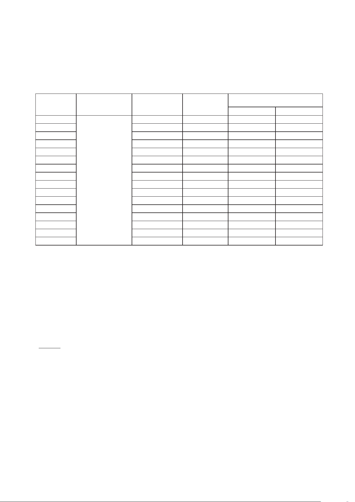
Piping Thickness and Material
•
Use the pipe as described below.
The thickness of refrigerant pipe differs depending on design pressure.
For copper pipe, pay attention to pipe selection, because the piping thickness differs depending on its
material.
Outer Diameter
1/4 (6.35) 0.03 (0.76) Annealed
3/8 (9.52) 0.032 (0.81) Annealed
1/2 (12.7) 0.032 (0.81) Annealed
5/8 (15.88) 0.035 (0.89) Annealed
3/4 (19.05) 0.035 (0.89) Hard Temper (or Annealed)
7/8 (22.2) 0.045 (1.14) Hard Temper
1-1/8 (28.58) 0.050 (1.27) Hard Temper
1-3/8 (34.93) 0.065 (1.65) Hard Temper
1-5/8 (41.28) 0.072 (1.83) Hard Temper
Thickness Temper
inch (mm)
R410A
NOTES:
• Do not use pipe that has allowable
pressure less than 601 psi (4.15MPa).
• The reference value of the refrigerant
piping thickness is indicated in the table
at left.
Do not use pipe that is considerably
different from the reference value.
P5417009-rev.6
9
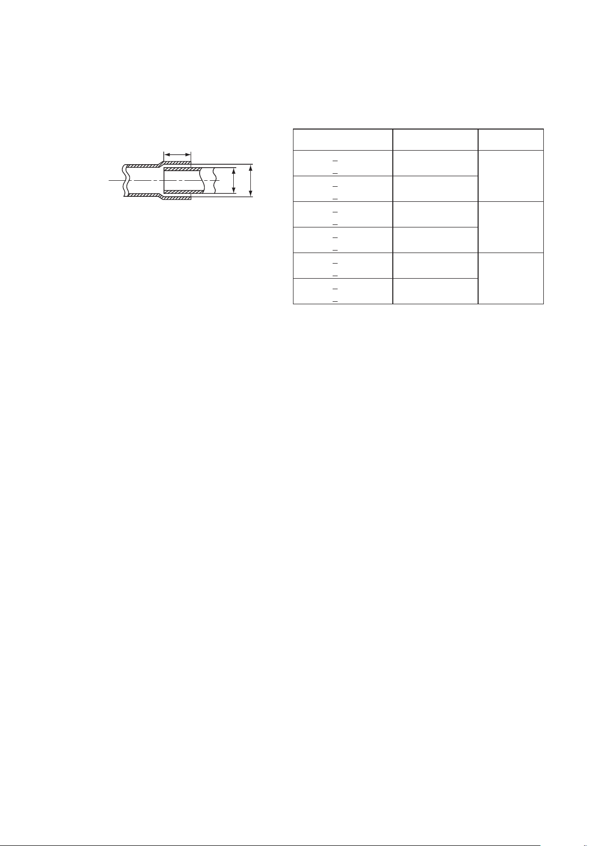
Processing at Brazing Connection
B
DA
•
To prevent gas leakage at the brazing connection, refer to the following table for the insertion depth and
the gap for the joint pipe.
3/16
(5
5/16
(8
1/2
(12
5/8
(16
(25
1-3/8
(35
Diameter
(D)
< D < 5/16
< D < 8)
< D < 1/2
< D < 12)
< D < 5/8
< D < 16)
< D < 1
< D < 25)
< D < 1-3/8
1
< D < 35)
< D < 1-3/4
< D < 45)
Min. Insertion Depth
(B)
1/4 (6)
9/32 (7)
5/16 (8)
3/8 (10)
1/2 (12)
9/16 (14)
(A - D)
0.002 - 0.014
(0.05 - 0.35)
0.002 - 0.018
(0.05 - 0.45)
0.002 - 0.022
(0.05 - 0.55)
inch (mm)
Gap
10
P5417009-rev.6

3.4 Line-Up of Outdoor Units
(1) This outdoor unit series can build the capacity of 72 to 432 MBH by combining the outdoor units of 72
to 192 MBH.
(2) The outdoor units of 216 to 432 MBH consist of the combination of two to three base units.
Use the combination of units in the following table. If the combinations are not listed, then they are not
available.
208/230V
Base Unit
Capacity (MBH) 72 96 120
Model (H,Y)VAHR072B32S (H,Y)VAHR096B32S (H,Y)VAHR120B32S
Capacity (MBH) 144 168 192
Model (H,Y)VAHR144B32S (H,Y)VAHR168B32S (H,Y)VAHR192B32S
Combination of Base Units
Capacity (MBH) 216 240 264 288
Model (H,Y)VAHR216B32S (H,Y)VAHR240B32S (H,Y)VAHR264B32S (H,Y)VAHR288B32S
Combination
Capacity (MBH) 312 336 360
Model (H,Y)VAHR312B32S (H,Y)VAHR336B32S (H,Y)VAHR360B32S
Combination
(H,Y)VAHR144B32S (H,Y)VAHR120B32S (H,Y)VAHR144B32S (H,Y)VAHR144B32S
(H,Y)VAHR072B32S (H,Y)VAHR120B32S (H,Y)VAHR120B32S (H,Y)VAHR144B32S
(H,Y)VAHR168B32S (H,Y)VAHR192B32S (H,Y)VAHR192B32S
(H,Y)VAHR144B32S (H,Y)VAHR144B32S (H,Y)VAHR168B32S
Capacity (MBH) 384 408 432
Model (H,Y)VAHR384B32S (H,Y)VAHR408B32S (H,Y)VAHR432B32S
(H,Y)VAHR144B32S (H,Y)VAHR144B32S (H,Y)VAHR144B32S
Combination
(H,Y)VAHR120B32S (H,Y)VAHR144B32S (H,Y)VAHR144B32S
(H,Y)VAHR120B32S (H,Y)VAHR120B32S (H,Y)VAHR144B32S
460V
Base Unit
Capacity (MBH) 72 96 120
Model (H,Y)VAHR072B42S (H,Y)VAHR096B42S (H,Y)VAHR120B42S
Capacity (MBH) 144 168 192
Model (H,Y)VAHR144B42S (H,Y)VAHR168B42S (H,Y)VAHR192B42S
Combination of Base Units
Capacity (MBH) 216 240 264 288
Model (H,Y)VAHR216B42S (H,Y)VAHR240B42S (H,Y)VAHR264B42S (H,Y)VAHR288B42S
Combination
Capacity (MBH) 312 336 360
Model (H,Y)VAHR312B42S (H,Y)VAHR336B42S (H,Y)VAHR360B42S
Combination
(H,Y)VAHR144B42S (H,Y)VAHR120B42S (H,Y)VAHR144B42S (H,Y)VAHR144B42S
(H,Y)VAHR072B42S (H,Y)VAHR120B42S (H,Y)VAHR120B42S (H,Y)VAHR144B42S
(H,Y)VAHR168B42S (H,Y)VAHR192B42S (H,Y)VAHR192B42S
(H,Y)VAHR144B42S (H,Y)VAHR144B42S (H,Y)VAHR168B42S
Capacity (MBH) 384 408 432
Model (H,Y)VAHR384B42S (H,Y)VAHR408B42S (H,Y)VAHR432B42S
(H,Y)VAHR144B42S (H,Y)VAHR144B42S (H,Y)VAHR144B42S
Combination
P5417009-rev.6
(H,Y)VAHR120B42S (H,Y)VAHR144B42S (H,Y)VAHR144B42S
(H,Y)VAHR120B42S (H,Y)VAHR120B42S (H,Y)VAHR144B42S
11

3.5 Combinations of Indoor Units and Outdoor Units
Table 3.1 Indoor Unit Model List
Capacity (MBH)
Ducted
Non-
Ducted
Indoor Unit Model
Ducted (High Static)
Ducted (Medium Static)
Ducted (Slim) (H,Y)IDS_B21S
Ducted (EconoFresh) (H,Y)IDM_B21E
Air Handler with DX-Kit (H,Y)MAHP_(B,C,D)21S
Ceiling-Mounted 4-Way Cassette (H,Y)IC4_B21S
Ceiling-Mounted 4-Way Cassette Mini (H,Y)ICM_B21S
Ceiling-Mounted 2-Way Cassette (H,Y)IC2_B21S
Ceiling-Mounted 1-Way Cassette (H,Y)IC1_B21S
Wall-Mounted TIWM_B21S
Ceiling Suspended (H,Y)ICS_B21S
Floor Exposed (H,Y)IFE_B21S
Floor Concealed (H,Y)IFC_B21S
(H,Y)IDH_B21S
(H,Y)IDH_B22S
(H,Y)IDM_B21S
(H,Y)IDM_B22S
6 8 12 15 18 24 27 30 36 48 54 60 72 96
: Available
NOTICE:
For connection to a Ducted (EconoFresh), see below.
● Ducted (EconoFresh) only:
Total capacity of Ducted (EconoFresh) is 70%~100% of the outdoor unit capacity.
● Ducted (EconoFresh) + Other Standard Indoor Unit:
Total capacity of Ducted (EconoFresh) is 30% or below the outdoor unit capacity.
and
Total capacity of indoor unit, including Ducted (EconoFresh) is 70%~100% of the outdoor unit capacity.
12
P5417009-rev.6
The number of indoor units that can be connected to an outdoor unit is dened in Table 3.2.
Comply with the following conditions when installing the unit.
A maximum and minimum total capacity as opposed to the nominal outdoor unit capacity can be obtained
through combination of indoor units.
Table 3.2 System Combination
Model: (H,Y)VAHR_B(3,4)2S
Outdoor Unit
Capacity
(MBH)
72
Minimum Capacity at
Individual Operation
(MBH)
Maximum Number
of Connectable I.U.
15 8 130% 70%
Recommended
Number of
Connected I.U.
Connectable Indoor Unit
Capacity Ratio
2,3,4,5
Maximum
Minimum
96 20 8 130% 65%
120 26 8 130% 60%
144 26 10 130% 55%
168 36 12 130% 55%
192 40 14 130% 55%
216 46 18 130% 60%
240 52 18 130% 60%
264 56 20 130% 55%
1
6
288 59 20 130% 55%
312 64 22 130% 55%
336 64 24 130% 55%
360 64 28 130% 55%
384 64 30 130% 55%
408 64 30 130% 55%
432 64 30 130% 55%
o
1. When the outdoor air temperature is 23
F (-5oC) or less during the outdoor unit cooling operation, the minimum
connectable indoor unit capacity is 18 MBH. A snow protection hood or low ambient kit (optional part) should be
installed.
2. When the outdoor air temperature is 109
o
F (43oC) or warmer during the outdoor unit cooling operation, the maximum
connectable indoor unit capacity ratio is 100%.
o
3. When the outdoor air temperature is 14
F (-10oC) or less, or under the high heating load conditions, the total indoor
unit capacity should be less than 100% of the outdoor unit capacity, and the total piping length should be less than
984 ft (300m).
4. When the number of connected indoor unit (I.U.) is within the recommended, the maximum connectable indoor unit
capacity ratio is available up to 150%.
5. There are some limitations of the Height Difference between Outdoor Units and Indoor Units.
Refer to Section 6.5 “Piping Size and Multi-kit Selection”, for details.
NOTICE:
The connectable indoor unit capacity ratio can be calculated as follows:
Connectable Indoor Unit Capacity Ratio = Total Indoor Unit Capacity / Total Outdoor Unit Capacity
In a system where all the indoor units operate simultaneously, the total indoor unit capacity should be less than the
outdoor unit capacity. Otherwise, a decrease in operating performance and an increase in the operating limit can result
in an overload.
In a system where all the indoor units do not operate simultaneously, the total indoor unit capacity is available up to
150% against the outdoor unit capacity.
The air ow volume for indoor units of 6 and 8 MBH is set higher than that for indoor units of 12 MBH or more.
Make sure to select appropriate indoor units for installation where a cold draft may occur during heating operation.
If installing indoor units in such locations, refer to the recommended number of indoor units as shown in above table
that can be connected.
P5417009-rev.6
13

3.6 Caution about Outdoor Unit Installation
: Maintain a straight-line distance of 19-11/16 inches (500mm) or more for piping after installing the piping connection kit.
>
>
>
>
A
A
NOTICE
When the installation and piping work for the multiple outdoor units is performed, it is required that you
determine the arrangement of the outdoor units and the piping length. Perform the installation work in strict
accordance with the following requirements.
If the arrangement for outdoor units is incorrect, it may cause owback of the refrigerant and result in failure
of the outdoor unit.
Requirements for Combining Two and Three Units
(1) When using a combination of two and three outdoor units, align the outdoor units from largest capacity
to smallest as A > B > C and outdoor unit “A” is connected to the piping connection kit 1.
(2) The piping length between the piping connection kit 1 and the outdoor unit should be
La < Lb < Lc < 32 ft (10m).
C
Outdoor Unit
C
B
Outdoor Unit
B
Outdoor Unit
A
Piping Connection Kit 1Piping Connection Kit 1
Indoor Unit
Side
Indoor Unit
Side
B
Outdoor UnitAOutdoor Unit
144 MBH 144 MBH 120 MBH 120 MBH 144 MBH 144 MBH
La LaLb LbLc Lc
Piping Direction Piping Direction
B
Piping Connection Kit 2 Piping Connection Kit 2
C
Outdoor Unit
C
3.7 Piping Work between Outdoor Units
When installing a combination unit, a piping connection kit is needed for each additional unit but not for the
base unit: (72, 96, 120, 144, 168, 192 Models). The piping connection kit (MC-NP**SX) consists of branch
pipes for low pressure gas, high/low pressure gas and liquid. Interconnecting pipe is not included in these
kits (eld-supplied).
Model: (H,Y)VAHR_B(3,4)2S
Operation
Outdoor Unit
Capacity
216 - 360 2 MC-NP21SX 1
Heat Recovery
384 - 432 3 MC-NP30SX 1
14
Applicable Outdoor Unit
Outdoor Unit
(MBH)
Number
Model Piping Set Remarks
3 Pipes Type
* for Low Pressure Gas
* for High/Low Pressure Gas
* for Liquid
P5417009-rev.6

4. Outdoor Unit Installation
Air Outlet
4.1 Installation Location and Precautions
To reduce the risk of serious injury or death, the following installation precautions must be followed.
● When installing the unit into…
▫ A wall: Make sure the wall is strong enough to hold the unit’s weight. It may be necessary to
construct a strong wood or metal frame to provide added support.
▫ A room: Properly insulate any refrigerant tubing run inside a room to prevent “sweating” that can
cause dripping and water damage to walls, oors, equipment, and property.
▫ Damp or uneven areas: Use a raised concrete pad or concrete blocks to provide a solid, level
foundation for the unit to prevent water damage and abnormal vibration.
▫ An area with high winds: Securely anchor the outdoor unit down with bolts and a metal frame.
Provide a suitable wind bafe (eld-supplied).
▫ A snowy area: Install the outdoor unit on a raised platform that is higher than the anticipated snow
levels and drifting snow. Provide snow protection hood or low ambient kit (optional part).
● Do not install the unit in the following places. Doing so can result in an explosion, re, deformation,
corrosion, or product failure.
▫ Explosive or ammable atmosphere
▫ Where a re, oil, steam or powder can directly enter the unit, such as nearby or above a kitchen
stove.
▫ Where oil (including machinery oil) may be present.
▫ Where corrosive gases such as chlorine, bromine, or sulde can accumulate, such as near a hot
tub or hot spring.
▫ Where dense, salt-laden airow is heavy, such as in coastal regions.
▫ Where the air quality is of high acidity.
▫ Where harmful gases can be generated from decomposition.
● During heating or defrosting operation, drain water is discharged. Provide adequate drainage around
the foundation. If installing the unit on a roof or a balcony, provide the additional drainage around the
foundation to prevent water from dripping on walk ways, people, property, and preventing ice from
forming during freezing temperatures creating slip hazards.
● Before performing any brazing work, be sure that there are no ammable materials or open ames
nearby.
● Perform a test run to ensure normal operation. Safety guards, shields, barriers, covers, and protective
devices must be in place while the compressor/unit is operating. During the test run, keep ngers and
clothing away from any moving parts.
● Clean up the site when nished, remembering to check that no tools, metal scraps, or bits of wiring
have been left behind inside the unit being installed.
After installation work for the system has been completed, explain the “Safety Precautions,” the proper use
and maintenance of the unit to the customer according to the information in all manuals that came with the
system. All manuals and warranty information must be given to the user or left near the Unit.
Seasonal
Wind
Snow attaches directly
to the heat exchanger.
Seasonal
Wind
Air Inlet
Hood
Provide a base which has
approximately twice the height of
forecast snow accumulation.
Hood
* Refer to the Engineering Manual for details of the optional part.
P5417009-rev.6
15

4.2 Service Space
Unit: inch (mm)
Side View
NOTICE:
Refer to the Engineering Manual for the outdoor unit when installing the low ambient kit.
When an outdoor unit is installed, allow sufcient clearance as follows:
•If there is insufcient clearance for air inlets and outlets, performance drop-off and mechanical issues due
to insufcient air intake may result.
•Additionally, adequate clearance is required for service maintenance access.
Min. 59-1/16
h2
Front
Side
(1500)
59-1/16
Min. 19-11/16 (500) + h2/2 Min. 11-13/16 (300) + h1/2
Rear
Side
30-1/8
(765)
(1500)
h1
19-11/16
(500)
- If there are no walls on the front and rear sides, clearance for service access is required as follows:
* Front Side: Minimum 19-11/16 inches (500mm)
* Rear Side: Minimum 11-13/16 inches (300mm)
* Right and Left Sides: Minimum 3/8 inches (10mm)
(In an instance where the snow protection hood (optional part) or the air outlet
duct (eld-supplied) is mounted to the unit, a minimum gap of 1-15/16 inches
(50mm) is required.)
- If the wall on the front side is over 59-1/16 inches (1,500mm) high, a clearance of (19-11/16 inches
(500mm) + h2/2) is required for the front side.
- If the wall on the rear side is over 19-11/16 inches (500mm) high, a clearance of (11-13/16 inches (300mm)
+ h1/2) is required for the rear side.
- When the units are surrounded by walls on more than two sides, observe the necessary clearance as
shown in the following illustrations.
- For walls on more than two sides, secure adequate clearance for service access space as shown in the
following illustrations.
- If the space between the unit and an obstacle above the unit is less than 59-1/16 inches (1,500mm) or
the space above the unit is closed, set up the duct at the air outlet side in order to prevent a short circuit.
- Make sure there is enough space in case the unit needs to be serviced and any of the four sides would
need to be opened or removed.
16
P5417009-rev.6

1) Walls on Two Sides
Min. 19-11/16 (500) + h2/2
is adopted, a minimum clearance of 2 inches (50mm) is required.
Unit: inch (mm)
Top View
Unit: inch (mm)
19-11/16 (500) + h2/2
Unit: inch (mm)
19-11/16 (500) + h2/2
If units are installed adjacent to tall buildings where there are two open sides, the minimum rear side
clearance must be at least 11-13/16 inches (300mm).
Single Installation Multiple / Serial Installation
No limit for
side wall height.
Min. 3/8
(10)
Front Side
Top View
Min. 11-13/16
(300)
(Rear Side Space)
No limit for
side wall height.
Min. 7-7/8
(200)
Front Side Front Side
Min. 15-3/4 (400)
Top View
Min. 11-13/16
(300)
(Rear Side Space)
: If using the snow protection hood (optional part) or the air outlet duct (field supplied)
is adopted, a minimum clearance of 2 inches (50mm) is required.
2) Walls on Three Sides
Single Installation
Min. 11-13/16 (300) + h1/2
Min. 3/8 (10)
Front Side
Min.
No limit for
side wall height.
Front Side Front Side
Min. 15-3/4 (400)
Top View
“”
This indicates the direction of the unit
(Front Side) when installing the units.
Min. 11-13/16
(300)
(Rear Side Space)
Min.
No limit for side wall height.
Multiple / Serial Installation
Installation in the Same Direction Rear to Rear Installation
Min. 11-13/16 (300) + h1/2
Min. 3/8
(10)
Front Side
Min. 13/16
(20)
Front
Side
Min. 19-11/16 (500)
Min. 13/16
(20)
Min.
19-11/16 (500) + h2/2
Min. 3/8
(10)
(Side Space)
Top View
: If the snow protection hood (optional part) or the air outlet duct (field supplied)
Front Side
Front
Side
Min. 13/16
(20)
No limit for side wall height.No limit for side wall height.
Top View
Min. 35-7/16 (900)
Min. 13/16
(20)
Min.
19-11/16 (500) + h2/2
P5417009-rev.6
17

3) Walls on Four Sides
Top View
No limit for
side wall height
Min.
Top View
side wall height.
Min.
(
Unit: inch (mm)
Top View
Unit: inch (mm)
Single Installation
No limit for
side wall height.
Min.
11-13/16 (300) + h1/2
Min. 7-7/8
(200)
31-1/2
800)
Open
▼
Front Side
Multiple / Serial Installation
Installation in the Same Direction Rear to Rear Installation
Min. 7-7/8
(200)
Min. 31-1/2
(800)
Open
.
▼ ▼▼
Front Side
▼▼▼
Front Side
Min. 7-7/8
(200)
Min. 7-7/8
(200)
Min. 7-7/8
(200)
No limit for
Min.
19-11/16 (500) + h2/2
11-13/16 (300) + h1/2
Min. 7-7/8
(200)
Min. 35-7/16 (900)
No limit for
side wall height.
Min. 31-1/2
(800)
Min.
19-11/16 (500) + h2/2
Open
Min. 7-7/8
(200)
(Side Space)
No limit for
side wall height.
Min. 31-1/2
(800)
Open
Front Side
▼▼▼
▼
Min. 7-7/8
(200)
▼▼
Front Side
Min. 7-7/8
(200)
Min.
19-11/16 (500) + h2/2
Min. 7-7/8
(200)
Min. 63 (1600)
No limit for
side wall height.
Min. 31-1/2
(800)
Min.
19-11/16 (500) + h2/2
Open
: Partly open a wall if the unit is surrounded by walls on four sides.
NOTICE:
Keep the upper side open to prevent mutual interference between the inlet and outlet air of each outdoor
unit.
The gure indicates sufcient clearance around the outdoor units for operation and maintenance at typical
installation conditions as follows.
[Operation Mode: Cooling Operation, Outside Temp.: 95
o
F (35oC)]
In the following situations when compared to the installation condition, an appropriate clearance
dimension is required by calculating air ow current when
* the outdoor unit ambient temperature is higher
* a short circuit is likely to occur
For the multiple installation of units, one group will consist of a maximum of six outdoor units.
Maintain a distance of 3.3 ft (1m) between each unit group.
One Group (Max. Six Outdoor Units)
Min. 3.3 ft
18
P5417009-rev.6

5. Transportation and Installation Work
Wooden Skid Base
Wooden Skid Base
Corrugated
Paper Frame
Plastic Bands
5.1 Transportation
Transport the product as close to the installation location as practical before unpacking.
When using a crane, hang the unit according to the description on the outdoor unit packing slip.
● Donothangtheunitwiththeslingbeltsatthewoodenskidbase.
Sling Belt Position
CORRECT INCORRECT
Sling Belt
Long Hole
Wooden Skid Base
Sling Belt
● TransportationandStorage:
* The protective corrugated cardboard is not strong enough to resist rough handling.
* Secure with two sling belts when hoisting the outdoor unit with a crane.
● TransportationandBandingWire:
* To protect the unit, do not remove
any packing.
* Donotstackorplaceanymaterial
on top of the product.
* Apply banding wire to both sides of
the packaged unit as shown at right.
Do not remove
corrugated paper
frame and plastic
bands.
Attach four 5/8 inch
(15mm) thick corrugated
corner pads as shown.
P5417009-rev.6
Banding Wire
19

Take special care when hanging or moving the outdoor unit because its center of mass is off-center and
Corrugated Paper Fram
(1,683)
Center
Front Side of Unit
unbalanced. See the diagram below.
Center of Gravity
inch (mm)
Voltage Model a b c d
72 38-3/8 (975) 21-1/4 (540) 24-5/8 (625) 12 (330)
66-1/4
of Gravity
208/230V
c
b
a
d
30-1/8
460V
(765)
96 48-5/8
120,144 48-5/8
168,192 64
72 38-3/8 (975) 21-7/16 (545) 25 (635) 12 (330)
96 48-5/8
120,144 48-5/8
168,192 64
(1,235) 25-13/16
(1,235)
(1,625)
(1,235)
(1,235)
(1,625)
(655) 26-9/16 (675) 13-3/8 (340)
27-3/8 (695) 25 (635)
32-7/8 (835) 24-3/16 (615)
26 (660)
26-15/16
(685) 13-3/8 (340)
27-3/8 (695) 25-3/8 (645)
33-1/16 (840) 24-5/8 (625)
12-13/16
12-13/16
12-13/16
12-13/16
Hanging Method
(1) Suspend the unit (with wooden skid base) in its packing with two sling belts as shown in Figure 5.1.
(2) Do not use banding wire.
(3) Ensure that the unit is balanced.
(4) Ensure safety while hoisting the unit gently to prevent the unit from tipping over.
Sling Belt
Do not remove
corrugated paper frame
and plastic bands.
Do not apply any force
to surface.
(Both Sides)
Wooden Skid Base
Carefully guide the sling belts through
both side slots of the wooden skid base.
Voltage Model
e
Min. 6.6 ft (2m)
Angle of sling belt
is more than 60o.
Top corners: Attach four 5/8 inch
(15mm) thick corrugated corner
pads as shown.
Bottom corners: Attach four
5/8 inch (15mm) thick cardboard
pads on both sides at
this point for protection.
208/230V
460V
72 527(239) 567(257)
96 598(271) 642(291)
120 730(331) 774(351)
144 732(332) 776(352)
168,192 860(390) 911(413)
72 534(242) 573(260)
96 611(277) 655(297)
120 734(333) 778(353)
Net
Weight
144 737(334) 781(354)
168,192 860(390) 911(413)
Gross
Weight
(325)
(325)
(325)
(325)
lbs (kg)
20
Figure 5.1 Hanging Unit on Wooden Skid Base for Transportation
(5) Hang the unit without a wooden skid base with two sling belts as shown in Figure 5.2.
Sling Belt
Min. 6.6 ft (2m)
Angle of sling belt
is more than 60o.
Top corners: Attach four 5/8 inch
(15mm) thick corrugated corner
pads as shown.
Bottom corners: Attach four
5/8 inch (15mm) thick cardboard
pads on both sides at this point
for protection.
Sling Belt
Position
Sling Belt
Slots
Sling Belt
Slots
Corrugated Paper Frame
Do not remove
CORRECT
INCORRECT
corrugated paper frame
and plastic bands.
Do not apply any force
to the surface.
(Both Sides)
Carefully guide the sling belts
through both side slots.
Figure 5.2 Hanging Unit without Wooden Skid Base
P5417009-rev.6

When using a forklift, do not insert forks into
Wo
Forks
The slots on
the unit side
Keep the appropriate interval
(at least 1-15/16 inches (50mm)).
Touching the Unit
Not Touching the Unit
the slots at the unit side panels. The unit can
sustain damage.
Do not apply excessive force to the squared
slots with forks or other materials. The bottom
of the unit can become deformed.
* Do not push the bottom base with forks.
* Do not use a roller.
Do not apply excessive force.
(Either Side)
Wooden Skid Base Removal Method
(1) Remove the hexagon head bolt using the ratchet wrench.
(2) Suspend the unit from the wooden skid base in its packing with two sling belts.
(3) Ensure safety while hoisting the unit gently to prevent the unit from tipping over as shown in Figure 5.3.
Ratchet
Wrench
Wrench
CORRECT
Outdoor Unit
INCORRECT
Outdoor Unit
oden Skid Base
Wooden Skid Base
Figure 5.3 Wooden Skid Base Removal Method
Duringtransportation,donotallowthebackrestoftheforklifttocomeintocontactwiththeunit.
Sudden forward movement on the forklift can cause damage to the unit heat exchanger.
Backrest
NOTICE
If transporting after unpacking, protect the unit with corrugated material, styrofoam, bubble pack, or a tarp.
P5417009-rev.6
21
 Loading...