

Page 1

HSM2HOST 2-Way Wireless Transceiver
Installation Manual
Page 2

2 HSM2HOST 2-Way Wireless Transceiver Installation Manual
© 2020 Johnson Controls. All rights reserved.
Page 3

Contents
Contents
Introduction.................................................................................................................................................... 5
Installation Process Overview............................................................................................................ 5
Controls and indicators....................................................................................................................... 5
Status LEDs................................................................................................................................................. 5
Tamper........................................................................................................................................................ 6
Safety instructions.......................................................................................................................................... 7
Specifications and features........................................................................................................................... 8
Compatible wireless devices......................................................................................................................... 9
Installing the HSM2HOST............................................................................................................................ 11
Temporary mounting requirements............................................................................................... 11
Connecting the HSM2HOST to the alarm panel............................................................................ 11
Enrolling The HSM2HOST................................................................................................................. 12
Enrolling the HSM2HOST without a hardwired keypad...................................................................... 12
Enrolling the HSM2HOST with an enrolled hardwired keypad.......................................................... 12
Enrolling the HSM2HOST with only unenrolled hardwired keypads................................................. 12
Permanently mounting the HSM2HOST and wireless devices.................................................... 12
Other Options.................................................................................................................................... 13
Enrolling and programming wireless devices.......................................................................................... 14
[804][000] Enrolling wireless devices.............................................................................................. 14
[804][001]-[716] Wireless Device Configuration............................................................................ 14
[804][801] RF Jam Detect.................................................................................................................. 15
[804][802] Wireless supervisory time window............................................................................... 15
[804][810] Wireless Option 1............................................................................................................ 16
[804][841] Motion cameras.............................................................................................................. 17
[804][901]-[905] Deleting wireless devices..................................................................................... 17
[804][921]-[925] Replacing wireless devices.................................................................................. 17
[804][990][001 – 005] Show all devices........................................................................................... 18
[804][999] Reset to factory defaults................................................................................................ 18
[904] Placement testing of wireless devices.................................................................................. 18
Programming Worksheets.......................................................................................................................... 20
[804] Wireless programming........................................................................................................... 20
[804][000] Wireless Device Enrollment – Zones............................................................................. 21
[804][000] Wireless device enrollment – Wireless keys................................................................ 22
[804][000] Wireless device enrollment – Wireless keypads.......................................................... 22
[804][000] Wireless device enrollment – Wireless repeaters....................................................... 23
[804][001]-[128] Configure wireless zones 1-128.......................................................................... 23
[804][551]-[566] Configure wireless sirens 1-16 (copy as needed)............................................. 25
[804][601]-[632] Configure Wireless Keys (copy as needed)........................................................ 26
[601]-[632] Wireless Key 1-32........................................................................................................... 26
[804]-[701]-[716] Wireless Keypad Programming......................................................................... 27
HSM2HOST 2-Way Wireless Transceiver Installation Manual 3
© 2020 Johnson Controls. All rights reserved.
Page 4

[804][841] Motion Cameras.................................................................................................................... 30
[804][901]-[905] Delete Wireless Devices.............................................................................................. 30
[804][921]-[925] Replace Wireless Devices........................................................................................... 30
[804][990] Show All Devices.................................................................................................................... 31
LIMITED WARRANTY.................................................................................................................................... 32
FCC Compliance Statement........................................................................................................................ 39
IC Statement...................................................................................................................................... 39
EU Compliance Statement................................................................................................................ 39
HSM2HOST 2-Way Wireless Transceiver Installation Manual4
© 2020 Johnson Controls. All rights reserved.
Page 5

Introduction
About this task:
The HSM2HOSTx two-way wireless transceiver adds wireless capability to alarm controllers, models
HS2016, HS2032, HS2064, HS2128, HS3128, HS3032.The HSM2HOST receives signals from wireless
zones and wireless keys, and provides information to the alarm controller. This manual describes
how to install, program and maintain the HSM2HOST.
Note: Only one HSM2HOST or one RFK keypad can be enrolled on the alarm system.
Before installing complete the following steps:
1. Plan the placement and wiring of the security system (see system installation manual).
2. Install the control panel and optional modules.
3. Temporarily mount all wireless devices in the intended location.
Installation Process Overview
About this task:
To install and set up the HSM2HOST and wireless devices:
1. Temporarily mount and wire the HSM2HOST module (See "Mounting").
2. Enroll the HSM2HOST and the first wireless keypad (See "Enroll The HSM2HOST").
3. Check the location for RF interference levels (See "[804][801] RF Jam Detect").
4. Enroll wireless devices (See "[804][000] Enroll Wireless Devices").
5. Complete zone and other programming on the system (See "Wireless Device Setup and
Programming").
6. Test the placement of all the wireless devices (See "[904] Placement Testing Wireless
Devices").
7. Permanently mount the HSM2HOST and wireless devices (See "Permanently Mount").
Controls and indicators
Status LEDs
The LEDs on the front of the HSM2HOST provide feedback regarding the installation, operation and
troubleshooting of the unit. The LEDs function as follows:
Table 1: Status LEDs
Red LED Operation
Module Power Up: On steady during module power-up sequence then off.
Slow flashing = update in progress
Firmware Update:
Rapid flashing = update failed
• No trouble: 1 rapid flash every 10 seconds.
If troubles are present, a series of flashes occur every 2 seconds. Each
series of flashes indicate troubles as follows:
Trouble Condition:
• 1 flash: Module not enrolled
• 2 flashes: Loss of contact with module for over 60 seconds
• 3 flashes: Corbus low voltage
• 8 flashes: RF interference (jam condition)
© 2020 Johnson Controls. All rights reserved.
5HSM2HOST 2-Way Wireless Transceiver Installation Manual
Page 6

Table 1: Status LEDs
Red LED Operation
Module Confirmation: Flashes rapidly during module confirmation process.
Placement Test: On steady when location is unsuitable. Off when location is suitable.
Green LED Operation
On steady when location is suitable. Off when location is unsuitable.
Placement Test:
Note: For UL/ULC listed systems, signal must be Strong. See
Wireless Device Status Indications for details.
Tamper
The HSM2HOST has built-in wall and case tampers. The tamper function is disabled by default on
the NA version (enabled on the EU version). The tamper function can be enabled or disabled in
Option 3, [804][810] Wireless Option 1. The case tamper activates when the case is opened and
restores when the case is closed. The wall tamper on the back of the unit is depressed by the
mounting surface when properly installed. If the unit is removed, the tamper activates. Ensure
the mounting surface is smooth and free of obstructions that block access to the rear of the unit.
Electrical wires should not run over or under the module when it is mounted.
Note: The built-in wall and case tamper must be installed and enabled for UL/ULC listed
Commercial/ Residential Burglary applications.
HSM2HOST 2-Way Wireless Transceiver Installation Manual6
© 2020 Johnson Controls. All rights reserved.
Page 7

Safety instructions
Read the safety information before you install the equipment.
Important: This equipment must be installed by a skilled person only. A skilled person is an
installer with appropriate technical training. The installer must be aware of potential hazards
during installation and measures available to minimize risks to the installer and other people.
• Before you install this equipment, disconnect all power sources (for example mains, battery,
and telephone line) connected to the alarm panel.
• Install the equipment indoors in a non-hazardous environment where the following
conditions are met:
- Pollution degree - Maximum 2
- Over voltages - Category II
• Internal wiring must be routed to prevent strain on wire and terminal connections, loose
terminal connections, and damage to conductor insulation.
• Instruct the user that there are no user serviceable parts in this equipment. All equipment
must be serviced by a skilled person.
© 2020 Johnson Controls. All rights reserved.
7HSM2HOST 2-Way Wireless Transceiver Installation Manual
Page 8

Specifications and features
• Current Draw: 60mA
• Voltage: Draws current from the PowerSeries Neo or PowerSeries Pro alarm controller
(10.8VDC to 12.5VDC) - (Limited Power Supply)
• Frequency: 433MHz (HSM2HOST4), 868MHz (HSM2HOST8), 912-919MHz (HSM2HOST9UL)
• Zones - can receive signals from up to 128 wireless zones, and 16 wireless keypads
• Supports up to 32 wireless keys or 32 panic pendants
• Supervisory - programmable supervisory window
• Can be wired up to 1000 ft. / 230 m from the main panel with 22 AWG wire
• Connects to Corbus
• Compatibility: The HSM2HOST is used with PowerSeries Neo or PowerSeries Pro alarm panels
• Operating temperature: NA= 0°C to +49°C (32°F to 122°F); EU= -10°C to +55°C
• Relative humidity: 93% non-condensing
• Built-in wall and case tampers
Note: For Commercial BURG (UL) the Supervisory window shall be set to 4 hours. For
Residential Fire (UL/ULC) the Supervisory window shall be set to 200 seconds. For Residential
BURG (UL/ULC) the supervisory window shall be set to 24 hours. For UL Home Healthcare
applications the supervisory window shall be set to 24 hours Only models operating in the
band 912-919 MHz are UL/ULC listed where indicated. Only UL approved devices are to be used
with UL/ULC listed systems.
HSM2HOST 2-Way Wireless Transceiver Installation Manual8
© 2020 Johnson Controls. All rights reserved.
Page 9

Compatible wireless devices
The HSM2HOSTx (x= 4/8/9) can receive signals from the devices listed in the following table. For
more information, refer to the individual device instruction sheet.
Note: Throughout this document, x in the model number represents the operating frequency
of the device for one of the following models: 9 (912-919 MHz), 8 (868MHz), 4 (433MHz).
Table 2: Compatible wireless devices
Alarm Controllers
HS2016/HS2032/
Alarm Controllers
Modules
Wireless keypads
Wireless Devices
PowerG wireless short range ceiling mount detector with temperature
monitoring
PowerG wireless long range ceiling mount detector with temperature
monitoring
PowerG wireless outdoor curtain PIR
PowerG wireless PRI motion detector with optional animal resistance
PowerG wireless PIR motion detector with temperature monitoring
PowerG wireless curtain PIR motion detector
PowerG wireless PIR motion detector with camera
PowerG wireless outdoor PIR motion detector with camera and with antimasking
PowerG wireless mirror optic PIR motion detector
PowerG wireless dual technology (PIR and MW) with anti-masking
PowerG wireless outdoor PIR motion detector with anti-masking PGx994
PowerG wireless recessed door/window contact PGx307
PowerG wireless outdoor contact with auxiliary input, temperature monitoring,
and anti-masking
PowerG wireless door/window contact with auxiliary input
HS2064/HS2128/
HS3032/HS3128/
HS3248
HS2LCDWFx/
HS2LCDWFPx/
HS2LCDWFPVx
PGx862
PGx872
PGx902
PGx904(P)
PGx914(P)
PGx924
PGx934(P)
PGx944(P)
PGx974(P)
PGx984(P)
PGx312
PGx945
UL
UL
UL
UL
UL
UL
UL
UL
UL
UL
UL
UL
PowerG wireless vanishing door/window contact
PowerG wireless glassbreak detector
PowerG wireless shock detector with auxiliary input
PowerG wireless flood detector
© 2020 Johnson Controls. All rights reserved.
PGx975UL/
PGx303
UL
PGx912UL/
PGx922
PGx935
PGx985
UL
UL
UL
9HSM2HOST 2-Way Wireless Transceiver Installation Manual
Page 10

Table 2: Compatible wireless devices
PowerG wireless temperature detector
PGx905
UL
PowerG wireless temperature probe extender (requires PGx905) PGTEMP-PROBE
PowerG wireless CO detector (US only)
PowerG wireless CO detector with temperature monitoring
PowerG wireless smoke and heat detector
PowerG wireless smoke and heat detector with temperature monitoring
PowerG wireless smoke detector
PowerG wireless outdoor siren
PowerG wireless repeater
PowerG wireless 1-button security panic key
PGx913
PGx933
PGx916
PGx936
PGx926
PGx901
PGx911
PGx920
PGx938
PGx949
UL
UL
UL
UL
UL
UL
UL
UL
UL
UL
PowerG wireless 2-button security panic key
PowerG wireless 4-button security panic key
Note: Devices are not compatible in all markets.
PGx929
PGx939
PGx929
PGx939
UL
UL
UL
UL
HSM2HOST 2-Way Wireless Transceiver Installation Manual10
© 2020 Johnson Controls. All rights reserved.
Page 11
Installing the HSM2HOST
This section describes how to install the HSM2HOST module.
Temporary mounting requirements
Before installing the HSM2HOST, you must temporarily mount the HSM2HOST in a location that
meets the following requirements.
• Ensure that the location is dry.
• Ensure that the location is within the operating temperature range.
• Ensure that the location is central to the proposed placement of all wireless devices.
• Mount the module in a high location. Mounting the module below ground level can reduce
the range of the system.
• Mount the module in a location that is far away from sources of interference, such as
computers, electric motors, appliances, heating, air conditioning units, and other sources
of electrical noise. Large metal objects like heating ducts and plumbing can also shield the
electromagnetic waves
• Ensure that there are no obstructions blocking the rear of the unit.
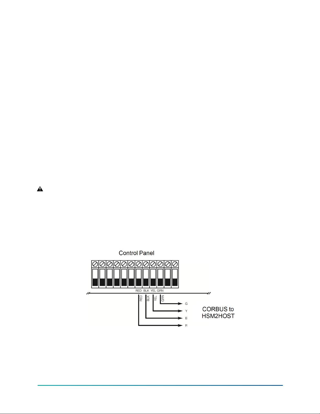
Connecting the HSM2HOST to the alarm panel
About this task:
WARNING: Ensure that you disconnect all power supplies from the system before connecting
the modules to the Corbus. Power supplies can include AC, DC, and telephone lines.
To connect the HSM2HOST to the alarm panel, complete the following steps:
1. Connect the HSM2HOST to the four-wire Corbus in the alarm panel. For more information,
see Figure 1.
2. Turn on the system.
Figure 1: Wiring Diagram
© 2020 Johnson Controls. All rights reserved.
11HSM2HOST 2-Way Wireless Transceiver Installation Manual
Page 12

Enrolling The HSM2HOST
The enrollment of a HSM2HOST to an alarm panel is dependent on the system configuration.
Enrolling the HSM2HOST without a hardwired keypad
About this task:
To enroll the HSM2HOST without a hardwired keypad, complete the following steps:
1. Turn on the wireless keypad by connecting the power source.
2. Simultaneously press [*] and [1] on the keypad.
Note: The system can take up to 30 seconds to complete the enrollment.
Enrolling the HSM2HOST with an enrolled hardwired keypad
About this task:
To enroll the HSM2HOST with an enrolled hardwired keypad, complete the following steps:
1. On the enrolled keypad, enter Installer Programming section [902][000] (Auto Enroll All
Modules).
2. When the system prompts you, press [*].
Enrolling the HSM2HOST with only unenrolled hardwired keypads
About this task:
To enroll the HSM2HOST with only unenrolled hardwired keypad(s), complete the following steps:
1. Enroll only one hardwired keypad onto the system by pressing any key on the keypad.
2. Enter Installer Programming section [902][000](Auto Enroll All Modules).
3. When the system prompts you, press [*] to enroll the HSM2HOST and all other keypads or
modules on the system.
Permanently mounting the HSM2HOST and wireless devices
About this task:
After a suitable location to permanently mount the HSM2HOST and wireless devices is found,
complete the following steps:
1. Pull the Corbus wires through the holes at the back of the HSM2HOST cabinet.
2. Using a screwdriver, securely mount the HSM2HOST cabinet to the wall using the three screw
supplied. For more information, see Figure 2.
3. To install the wall tamper, securely attach the breakaway wall tamper bracket to the wall
using the screws supplied (ST#6 L1" PHIL FLAT ST ZN).
4. Install the wireless devices. For more information, refer to the device's Installation Guide.
HSM2HOST 2-Way Wireless Transceiver Installation Manual12
© 2020 Johnson Controls. All rights reserved.
Page 13

Figure 2: Mounting the HSM2HOST
Other Options
The following actions can be performed on the HSM2HOST:
Section Action
[902][106] Delete the HSM2HOST from the alarm system.
[903][106] Confirm that the HSM2HOST is enrolled.
[000][806] Add a label to appear on LCD keypads.
[900][461] View HSM2HOST model information.
© 2020 Johnson Controls. All rights reserved.
13HSM2HOST 2-Way Wireless Transceiver Installation Manual
Page 14

Enrolling and programming wireless devices
This section describes how to enroll and program wireless devices such as contacts, motion sensors
and sirens on the alarm panel.
[804][000] Enrolling wireless devices
About this task:
After the HSM2HOST is installed and enrolled on the alarm panel, wireless devices can be enrolled
using the following method:
1. Enter Installer Programming section [804][000].
2. When prompted, either activate the device (see device installation sheet) to enroll
immediately or enter a device ID number. Do the latter to pre-enroll devices then enroll them
later at the customer site. The alarm panel determines the type of device being enrolled and
presents the appropriate programming options.
Table 3: Wireless Device Options
Device Type Programming Options
(01) Zone type
Zone
Wireless Key
Siren
Repeater (01) Repeater label
3. Use the scroll keys or type in the corresponding number to select an option.
4. Scroll through the available selections, key in a number or enter text as appropriate.
5. Press [*] to accept and move to the next option.
6. After all options are configured, the system prompts you to enroll the next device.
7. Repeat the above steps until all wireless devices are enrolled.
Note: The configuration options listed above can be modified using [804][911] Modify
Device.
(02) Partition assignment
(03) Zone label
(01) Partition assignment
(02) User label
(01) Partition assignment
(02) Siren label
[804][001]-[716] Wireless Device Configuration
To configure wireless devices, complete the following steps:
1. Enter Installer Programming section [804] then select one of the following sub-sections:
- 001-248 – Configure Wireless Zones
- 601-632 – Configure Wireless Keys
- 701-716 – Configure Wireless Keypads
2. Select a device to configure using the scroll keys or go directly to a specific device by entering
a hotkey.
HSM2HOST 2-Way Wireless Transceiver Installation Manual14
© 2020 Johnson Controls. All rights reserved.
Page 15

3. Use the scroll buttons or enter a hotkey to select a configuration option for the device. See
wireless device installation sheets for details.
4. Press [*] to accept and move to the next option.
5. After all options are configured, the system returns to the base configuration menu.
6. Repeat the above steps to configure other wireless devices.
Note: The configuration options listed above can be modified using [804][911] Modify
Device.
[804][801] RF Jam Detect
About this task:
RF jam detection (continuous interfering transmissions on the radio network) can be turned on or
off. When on, RF jamming is logged and reported.
To configure RF jamming, complete the following steps:
1. Enter Installer Programming section [804][801] then select one of the following options:
Jamming detection and reporting is enabled/disabled.
00 Disabled
01 UL 20/20-USA Continuous RF jamming for 20 seconds
02 EN 30/60-Europe 30 seconds of accumulated jamming within 60 seconds
Class 6 30/60-
03
British
Note: Must be enabled for UL/ULC listed installations.
As EN (30/60) but reported only if the jamming duration exceeds 5 minutes
2. Press [*] to accept the selection.
3. Press [#] to exit the section.
[804][802] Wireless supervisory time window
About this task:
This option is used to program the length of time a wireless device can be absent from the system
before a fault is generated.
Before programming the wireless supervisory time window, note the following UL/ULC
specifications:
Table 4: UL/ULC wireless supervision specifications
UL/ULC specifications Maximum wireless supervision time window
UL Residential Burglary (UL1023) 24 hours
Home Health Care (UL1637) 24 hours
ULC Residential Burglary (ULC/ORD-C1023) 24 hours
UL Residential Fire (UL985) installations 200 seconds
UL Commercial Burglary (UL1610/UL365) 4 hours
ULC Residential Fire (ULC-S545) 4 hours
To program the wireless supervisory time window, complete the following steps:
1. Enter Installer Programming section [804][802].
2. Select one of the following options by scrolling or entering the hot key:
- 00 – Disabled
© 2020 Johnson Controls. All rights reserved.
15HSM2HOST 2-Way Wireless Transceiver Installation Manual
Page 16

- 01 – After 1 Hour
- 02 – After 2 Hours
- 03 – After 4 Hours
- 04 – After 8 Hours
- 05 – After 12 Hours
- 06 – After 24 Hours
3. Press [*] to accept the selection.
4. Press [#] to exit the section.
Result:
For EN installations, 1 hour or 2 hours must be selected.
When option 06 is used, which configures the system to generate fault conditions after a device has
been detected as absent for 24 hours, smoke detectors generate a fault condition after a maximum
of 18 hours when the 200s supervision toggle option is disabled.
[804][810] Wireless Option 1
About this task:
To program wireless options, complete the following steps:
1. Enter Installer Programming section [804][810].
2. Select one of the following options by scrolling or entering the hotkey:
01
02
03
04
05
RF
Delinquency
Wireless
Supervisory/
RF Jam Alarm
Wireless
Tamper
Fire
Supervision
Smart
Temperature
Reporting
On: the system cannot be armed if a wireless supervisory trouble exists.
An RF delinquency trouble is generated.
Off: wireless supervisory troubles do not prevent arming.
On: if a supervisory or jamming trouble occurs during Away arming, the
siren activates and the event is logged and reported.
Off: supervisory or RF jam troubles during Away arming do not activate
the siren or get logged and reported.
On: module tampers are logged and reported.
Off: module tampers are not logged or reported.
On: fire devices are supervised every 200 seconds. If the device fails to
report within this window, a supervision trouble is generated.
Off: fire devices follow the supervision window programmed in section
802, up to a maximum of 18 hours. The supervisory window can be
programmed with a higher value, but detectors still go into fault after
18 hours.
On: Wireless devices with smart temperature reporting support will
periodically report their ambient temperature to the control panel.
Off: Smart temperature reporting is disabled on all devices.
3. Press [*] to accept the selection and [#] to exit.
HSM2HOST 2-Way Wireless Transceiver Installation Manual16
© 2020 Johnson Controls. All rights reserved.
Page 17

[804][841] Motion cameras
About this task:
To program motion cameras, complete the following steps:
1. Enter Installer Programming section [804][841].
2. Select one of the following options by scrolling or entering the hotkey:
[001]
[002]
[003]
Visual
Verification
View Time
Window
View Other
Alarms
A maximum of 8 zones can be assigned to a PIR camera to initiate video capture. When an
alarm occurs on any of the 8 zones, the panel initiates video capture from the PIR camera.
On: Alarms trigger image capture from PIR Cameras
Off: Alarms do not trigger image capture from PIR Cameras
01 Alarm + 5 Minutes
02 Alarm + 15 minutes
03 Alarm + 1 Hour
Note: The Video on Demand via Integration sessions follow this
configuration.
01 Fire key enabled/disabled
02 Duress enabled/disabled
03 Medical key enabled/disabled
04 Panic key enabled/disabled
Note: Video on Demand by third-party integrators follow this
configuration.
Note: This option is only available with a PIR camera, for example the PGx934 or
PGx944.
[804][901]-[905] Deleting wireless devices
About this task:
To delete wireless devices, complete the following steps:
1. Enter Installer Programming section [804] then select one of the following sub-sections:
[901] – Delete wireless zone devices
[902] – Delete wireless key
[904] – Delete repeaters
[905] – Delete keypads
2. Scroll or enter a hotkey to select a device.
3. Press [*] to delete or [#] to exit.
[804][921]-[925] Replacing wireless devices
About this task:
Use this option to replace a faulty device enrolled on the system with another device of the same
type while maintaining the configuration of the original. The faulty device does not need to be
deleted.
© 2020 Johnson Controls. All rights reserved.
17HSM2HOST 2-Way Wireless Transceiver Installation Manual
Page 18

To replace a wireless device, complete the following steps:
1. Enter Installer Programming section [804] then select one of the following sub-sections:
[921] – Replace wireless zone devices
[922] – Replace wireless key
[924] – Replace repeaters
[925] – Replace keypads
2. Press [*] to select a sub-section. The first available device is displayed.
3. Scroll or enter a hotkey to select a device, press [*].
4. When prompted, activate the device (full enrollment) or enter the device ID (pre-enrollment).
A message is displayed confirming enrollment.
[804][990][001 – 005] Show all devices
About this task:
Use this section to review wireless devices enrolled on the system and to view serial numbers
associated with each device.
To review wireless device information, complete the following steps:
1. Enter Installer Programming section [804][990] then select one of the following sub-sections:
- [001] – All zones
- [002] – Repeaters
- [004] – Wireless keys
- [005] – keypads
2. Press [*] to select a wireless device type. The first available device is displayed.
3. Use the scroll keys to view the enrolled devices.
Note: This option is not fully supported by LED and ICON keypads.
[804][999] Reset to factory defaults
Selecting this option resets HSM2HOST programming to factory default settings.
[904] Placement testing of wireless devices
This test is used to determine RF signal status for wireless devices and can be performed at a
system keypad or at the individual device. These instructions pertain to testing at the keypad. For
instructions on placement testing at the device, refer to the installation sheet provided with the
wireless equipment. The following test modes are available:
[904][001]-[128] Test wireless zones
[904][521]-[528] Test all repeaters
[904][551]-[566] Test all sirens
[904][601]-[632] Test all wireless keys
[904][701]-[716] Test all keypads Test each enrolled keypad. 701-716 for keypads 1-16
Test wireless devices individually by zone. Zones with
vanishing contacts must be activated to placement test.
Test each enrolled wireless repeater. 521-528 for
repeaters 1-8
Test each enrolled wireless siren. 551-566 for sirens
1-16
Test individual wireless keys. Once in this section, press
a button on the wireless key to begin the test. 601-632
for wireless keys 1-32.
HSM2HOST 2-Way Wireless Transceiver Installation Manual18
© 2020 Johnson Controls. All rights reserved.
Page 19

Two test results are provided:
• 24-hour: Average results of signal strength testing over a 24-hour period.
• Now: Signal status results of the current test.
A flashing Trouble LED indicates RF interference. The following status indicators may be displayed:
LCD Icon* LED+ Status
Strong 1 9 Strong signal strength
Good 2 10 Good signal strength
Poor 3 11 Poor signal strength
Not Test 5 13 Displayed as the Now result if no test was performed
Not Test 5 13
Always displayed as the 24-hour result when testing
wireless keys
*For Icon keypads, digit 1 indicates 24-hour test results; digit 2 indicates Now test results.
+For LED keypads, the first digit indicates 24-hour results; the second digit indicates Now test
results.
Note: For EN/UL/ULC installations, only strong signal levels are acceptable.
© 2020 Johnson Controls. All rights reserved.
19HSM2HOST 2-Way Wireless Transceiver Installation Manual
Page 20

Programming Worksheets
Use these pages to record custom programming options (Installers Programming: [*][8]).
000 - Auto Enroll
Enroll Module
[902]
Delete Module
[903] Confirm Module
001 - Enroll Modules
002 - Module Slot Assignment (LED/ICON)
003 - Module Slot Assignment (LED only)
101 - Delete Keypads
102 - Delete Zone Expander
103 - Delete Output Expander
106 - Delete HSM2HOST
108 - Delete Audio Verification
109 - Delete Power Supply
001 - Confirm Keypad
002 - Confirm Zone Expander
003 - Confirm Output Expander
006 - Confirm HSM2HOST
008 - Confirm Audio Verification
009 - Confirm Power Supply
[804] Wireless programming
Enroll Wireless Device
Zone
[000]
Wireless Key
Siren
Keypad
Repeater
HSM2HOST 2-Way Wireless Transceiver Installation Manual20
© 2020 Johnson Controls. All rights reserved.
Page 21

[804][000] Wireless Device Enrollment – Zones
Zone Label
Zone
Definition
Zone
Type
Partition
© 2020 Johnson Controls. All rights reserved.
21HSM2HOST 2-Way Wireless Transceiver Installation Manual
Page 22

[804][000] Wireless device enrollment – Wireless keys
Key#
1 17
2 18
3 19
4 20
5 21
6 22
7 23
8 24
9 25
10 26
11 27
12 28
13 29
14 30
Partition
#
User Label Key#
Partition
#
User Label
15 31
16 32
[804][000] Wireless device enrollment – Wireless keypads
WLS
Keypad
#
1 9
2 10
3 11
4 12
5 13
6 14
7 15
8 16
Keypad
Assignment
Keypad Label
WLS
Keypad
#
Keypad
Assignment
Keypad Label
HSM2HOST 2-Way Wireless Transceiver Installation Manual22
© 2020 Johnson Controls. All rights reserved.
Page 23

[804][000] Wireless device enrollment – Wireless repeaters
Repeater
#
1
2
3
4
5
6
7
8
Repeater Label
[804][001]-[128] Configure wireless zones 1-128
Zone#:
Toggle Options
[001] Device Options [003] High Traffic Shutdown
x 01 – Alarm LED x 01 – Not Active
x 02 – Reed Switch 02 – Yes - No Delay
03 – External Input On 03 – Yes - 5s Delay
x 04 – Supervision 04 – Yes - 15s Delay
05 – Not Used 05 – Yes - 30s Delay
06 – Not Used 06 – Yes - 1m Delay
07 – Anti- Masking 07 – Yes - 5m Delay
08 – Not Used 08 – Yes - 10m Delay
09 – Shock Accumulator 09 – Yes - 20m Delay
10 – Not Used 10 – Yes - 60m Delay
x 11 – 24hr/Night [004] Image Brightness
12 – Not used 01 – Image Bright -3
13 – Not Used 02 – Image Bright -2
x 14 – Fire Alarm 03 – Image Bright -1
15 – Not Used x 04 – Image Bright 0
16 – Not Used 05 – Image Bright +1
[002] Zone EOL 06 – Image Bright +2
00 – Disable 07 – Image Bright +3
x 01 – Single EOL
23HSM2HOST 2-Way Wireless Transceiver Installation Manual
© 2020 Johnson Controls. All rights reserved.
Page 24

Zone#:
Toggle Options
02 – Normally Open
03 – Normally Closed
04 – Double EOL
Zone#:
Toggle Options
[005] Image Contrast [011] - Camera Toggles
01 – Image Contrast -3 01- Color
02 – Image Contrast -2 02 - High Resolution
03 – Image Contrast -1 03 - Low Quality
04 – Image Contrast - 0 04 - Microphone
05 – Image Contrast +1 05 - Video on Demand
06 - Video on Demand (away only) override
06 – Image Contrast +2
Note: This overrides [851][010] Option 5
Video on Demand in away mode only, when
enabled.
07 – Image Contrast +3 [016] Event Counter
001-002 (Default: 002)
[006] Detection Range [018] Shock Sensitivity
01 - Low Sensitivity 001-019 (Default: 008)
02- Mid Sensitivity [019] High Temperature Warning
03 - High Sensitivity +/- 000 to 999
[007] Detection Security [020] High Temperature Alarm
01 - Low Sensitivity +/- 000 to 999
02 - High Sensitivity +/- 000 to 999
03-UL Standard [022] Low Temperature Alarm
+/- 000-999c (Default: 999c)
[010] Anti-masking [025]-[032] Camera Zone Assignment
01- Disabled
02- Low Sensitivity
03- High Sensitiity
HSM2HOST 2-Way Wireless Transceiver Installation Manual24
© 2020 Johnson Controls. All rights reserved.
Page 25

[804][551]-[566] Configure wireless sirens 1-16 (copy as needed)
Zone#
Toggle Options
[000] Partition Assignment 1 2 3 4 5 6 7 8
[001] Device Toggles [002] Strobe Alarm [004] Squawk
x 01 – Fire Alarm 01 – Disabled 01 – Disabled
x 02 – Gas/CO Alarm x 02 – Timer Limited x 02 – Sounder Only
x 03 – Burglary Alarm 03 – Until Disarmed 03 – Strobe Only
x 04 – Flood Alarm [003] Exit Entry Beeps 04 – Sounder/Strobe
05 – Not Used x 01 – Disabled [005] Sounder Volume
06 – Auto Temp Alarm 02 – Enabled 01 – Low
07 – Activity LED 03 – Disabled Stay x 02 – Medium
08 – Not Used 03 – High
09 – AC Power
x 10 – Buzzer Notification
x 11 – Door Chime
x 12 – Trouble Beep
25HSM2HOST 2-Way Wireless Transceiver Installation Manual
© 2020 Johnson Controls. All rights reserved.
Page 26

[804][601]-[632] Configure Wireless Keys (copy as needed)
[000] Wireless Key Partition Assignment (Default: 01)
[001]-[005] Wireless Key Button Programming (Defaults: Key 1: 04, Key 2: 03, Key 3: 01, Key 4: 52,
Key 5: 21)
[011] Wireless Key Device Toggles (Default: 01)
[020] Wireless Key User Assignment (Default: 00 – Not Assigned)
Available programming options:
00- Disabled (Null)
01- Disarm
02- Instant Stay Arm
03- Stay Arm
04- Away Arm
05- [*][9] No Entry
06- Chime On/Off
07- System Test
09- Night Arm
12- Global Stay Arm
13- Global Away Arm
14- Global Disarm
15- Temperature
16- Quick Exit
17- Arm Interior
21- Comm. Output 1
22- Comm. Output 2
23- Comm. Output 3
24- Comm. Output 4
29- Bypass Group
Recall
33- Bypass Recall
51- [M] Key Alarm
52- [P] Key Alarm
[601]-[632] Wireless Key 1-32
Wireless Key# Partition Button Supervision Yes No User Number
1:
2:
1 2 3 4 5 6 7 8
Wireless Key# Partition Button Supervision Yes No User Number
3:
4:
5
1:
x
2:
1 2 3 4 5 6 7 8
Wireless Key# Partition Button Supervision Yes No User Number
1 2 3 4 5 6 7 8
© 2020 Johnson Controls. All rights reserved.
3:
4:
5
1:
2:
3:
4:
5
x
x
HSM2HOST 2-Way Wireless Transceiver Installation Manual26
Page 27

Wireless Key# Partition Button Supervision Yes No User Number
1:
2:
1 2 3 4 5 6 7 8
Wireless Key# Partition Button Supervision Yes No User Number
1 2 3 4 5 6 7 8
3:
4:
5
1:
2:
3:
4:
5
x
x
[804]-[701]-[716] Wireless Keypad Programming
Keypad
#
[000] Partition Assignment 00 – Global 03 – Partition 3 03 – Partition 3
x 01 – Partition 1 04 – Partition 4 04 – Partition 4
02 – Partition 2 05 – Partition 5 05 – Partition 5
© 2020 Johnson Controls. All rights reserved.
27HSM2HOST 2-Way Wireless Transceiver Installation Manual
Page 28

Function Key Programming Options
00 - Null Key
13 - Global Away Arm
02 - Instant Stay Arm
14 - Global Disarming
03 – Stay Arm
15 - Temperature
04 - Away Arm
16 - Quick Exit
05 - [*][9]No Entry
Arm
06 - Chime On/Off
07 - System Test
09 - Night Arm
11 - Away Arm no
17 - Arm Interior
21 - Command Output 1
22 - Command Output 2
23 - Command Output 3
24 - Command Output 4
Entry
29 - Bypass Group Recall
12 - Global Stay Arm
[001] – Key 1:
Function Key:
(Default: 03)
[002] – Key 2:
30 - Quick Bypass
31 - Local PGM Active
32 - Bypass Mode
33 - Bypass Recall
34 - User
Programming
35 - User Functions
36 - Reactivate Stay/
Away/Night zones
37 - Time/Date
Programming
39 - Trouble Display
40 - Alarm Memory
[003] – Key 3:
(Default: 06)
[004] – Key 4:
61 - Partition Select 1
62 - Partition Select 2
63 - Partition Select 3
64 - Partition Select 4
65 - Partition Select 5
66 - Partition Select 6
67 - Partition Select 7
68 - Partition Select 8
[005] – Key 5:
(Default: 16)
(Default: 04)
(Default: 22)
[011] Keypad I/O (Zone number or output number; 3-digit decimal; Default: 000)
Pulse Time (Default:00 minutes):
[012] Local PGM Output Timer:
Pulse Time (Default:05 minutes):
[021] Keypad Option 1 x 01 – [F] Key Enabled
x 02 – [M] Key Enabled
x 03 – [P] Key Enabled
x 04 – Display Code or X's
[022] Keypad Option 1 x 01 – Local Clock Display
02 – Local Clock 24-Hour
x 03 – Auto Alarm Scroll
x 05 – Power LED
x 06 – Power LED AC Present
x 07 – Alarms Displayed if Armed
x 08 – Auto Scroll Open Zones
HSM2HOST 2-Way Wireless Transceiver Installation Manual28
© 2020 Johnson Controls. All rights reserved.
Page 29

01 – Armed LED Power Save
x 02 – Keypad Status Shows Arm Mode
[023] Keypad Option 3
03 – 5th Terminal is PGM Output/Zone Input
07 – Local Display of Temperature
08 – Low Temperature Warning
[030] LCD Message:
[031] Downloaded LCD Message Duration (3-digit decimal; 000-255; Default: 000):
[041] Indoor Temperature Zone Entry (3-digit decimal; 000-128; Default: 000):
[042] Outdoor Temperature Zone Entry (3-digit decimal; 000-128; Default: 000):
[101]-[128] Door Chime
Beeps:
00 – Disabled
x 01 – 6 beeps
02 – Bing Bong
03 – Ding Dong
04 – Alarm Tone
05 – Zone Name
Door Chime Zone Assignment:
1 ____ 2 ____ 3 ____ 4 ____ 5 ____ 6 ____ 7 ____ 8 ____ 9 ____ 10 ____
11 ____ 12 ____ 13 ____ 14 ____ 15 ____ 16 ____ 17 ____ 18 ____ 19 ____ 20 ____
21 ____ 22 ____ 23 ____ 24 ____ 25 ____ 26 ____ 27 ____ 28 ____ 29 ____ 30 ____
31 ____ 32 ____ 33 ____ 34 ____ 35 ____ 36 ____ 37 ____ 38 ____ 39 ____ 40 ____
41 ____ 42 ____ 43 ____ 44 ____ 45 ____ 46 ____ 47 ____ 48 ____ 49 ____ 50 ____
51 ____ 52 ____ 53 ____ 54 ____ 55 ____ 56 ____ 57 ____ 58 ____ 59 ____ 60 ____
61 ____ 62 ____ 63 ____ 64 ____ 65 ____ 66 ____ 67 ____ 68 ____ 69 ____ 70 ____
71 ____ 72 ____ 73 ____ 74 ____ 75 ____ 76 ____ 77 ____ 78 ____ 79 ____ 80 ____
81 ____ 82 ____ 83 ____ 84 ____ 85 ____ 86 ____ 87 ____ 88 ____ 89 ____ 90 ____
91 ____ 92 ____ 93 ____ 94 ____ 95 ____ 96 ____ 97 ____ 98 ____ 99 ____ 100 ___
101 ___ 102 ___ 103 ___ 104 ___ 105 ___ 106 ___ 107 ___ 108 ___ 109 ___ 110 ___
111 ___ 112 ___ 113 ___ 114 ___ 115 ___ 116 ___ 117 ___ 118 ___ 119 ___ 120 ___
121 ___ 122 ___ 123 ___ 124 ___ 125 ___ 126 ___ 127 ___ 128 ___
[804][801] Jam Detect
UL EN UL EN Disabled UL
[804][802] Supervisory
Window
[804][810] Wireless Options
E
N
Disabled After 1 Hour
© 2020 Johnson Controls. All rights reserved.
1 – RF Delinquency
Tamper
29HSM2HOST 2-Way Wireless Transceiver Installation Manual
Page 30

x UL – UL 20/20 x After 2 Hours x 2 – Missing/Jam Alarm
x EN 30/60 After 4 Hours 3 – Wireless Tamper
Class 6
(30/60)
[804][841] Motion Cameras
001 Visual Verification
002 View Time Window
003 View Other Alarms
After 8 Hours
After 12
Hours
x
After 24
Hours
01 – Disabled
x 02 – Enabled
03 – Enabled
x 01 – Alarm + 5 Minutes
02 – Alarm + 15 Minutes
03 – Alarm + 1 Hour
x 01 – Fire Alarm
x 02 – Duress Alarm
x 03 – Medical Alarm
x 04 – Panic Alarm
4 – 200s Fire
Supervision
5- Smart Temperature
Reporting
[804][901]-[905] Delete Wireless Devices
[901] Delete Zones
[902] Delete Wireless Keys
[903] Delete Sirens
[904] Delete Repeaters
[905] Delete Keypads
[804][921]-[925] Replace Wireless Devices
[921] Replace Zones
[922] Replace Wireless Keys
[923] Replace Sirens
[924] Replace Repeaters
[925] Replace Keypads
HSM2HOST 2-Way Wireless Transceiver Installation Manual30
© 2020 Johnson Controls. All rights reserved.
Page 31

[804][990] Show All Devices
[001] Show All Zones
[002] Show All Repeaters
[003] Sirens
[004] Wireless Keys
[005] Keypads
© 2020 Johnson Controls. All rights reserved.
31HSM2HOST 2-Way Wireless Transceiver Installation Manual
Page 32

LIMITED WARRANTY
LIMITED WARRANTY
Digital Security Controls warrants the original purchaser that for a period of twelve months from
the date of purchase, the product shall be free of defects in materials and workmanship under
normal use. During the warranty period, Digital Security Controls shall, at its option, repair or
replace any defective product upon return of the product to its factory, at no charge for labour and
materials. Any replacement and/or repaired parts are warranted for the remainder of the original
warranty or ninety (90) days, whichever is longer. The original purchaser must promptly notify
Digital Security Controls in writing that there is defect in material or workmanship, such written
notice to be received in all events prior to expiration of the warranty period. There is absolutely no
warranty on software and all software products are sold as a user license under the terms of the
software license agreement included with the product. The Customer assumes all responsibility for
the proper selection, installation, operation and maintenance of any products purchased from DSC.
Custom products are only warranted to the extent that they do not function upon delivery. In such
cases, DSC can replace or credit at its option.
International Warranty
The warranty for international customers is the same as for any customer within Canada and the
United States, with the exception that Digital Security Controls shall not be responsible for any
customs fees, taxes, or VAT that may be due.
Warranty Procedure
To obtain service under this warranty, please return the item(s) in question to the point of
purchase. All authorized distributors and dealers have a warranty program. Anyone returning
goods to Digital Security Controls must first obtain an authorization number. Digital Security
Controls will not accept any shipment whatsoever for which prior authorization has not been
obtained.
Conditions to Void Warranty
This warranty applies only to defects in parts and workmanship relating to normal use. It does not
cover:
• damage incurred in shipping or handling
• damage caused by disaster such as fire, flood, wind, earthquake or lightning;
• damage due to causes beyond the control of Digital Security Controls such as excessive
voltage, mechanical shock, water damage;
• damage caused by unauthorized attachment, alterations, modifications or foreign objects;
• damage caused by peripherals (unless such peripherals were supplied by Digital Security
Controls Ltd.);
• defects caused by failure to provide a suitable installation environment for the products;
• damage caused by use of the products for purposes other than those for which it was
designed;
• damage from improper maintenance;
• damage arising out of any other abuse, mishandling or improper application of the products.
Items Not Covered by Warranty
In addition to the items which void the Warranty, the following items shall not be covered by
Warranty: (i) freight cost to the repair centre; (ii) products which are not identified with DSC's
product label and lot number or serial number; (iii) products disassembled or repaired in such a
manner as to adversely affect performance or prevent adequate inspection or testing to verify any
HSM2HOST 2-Way Wireless Transceiver Installation Manual32
© 2020 Johnson Controls. All rights reserved.
Page 33

warranty claim. Access cards or tags returned for replacement under warranty will be credited or
replaced at DSC's option. Products not covered by this warranty, or otherwise out of warranty due
to age, misuse, or damage shall be evaluated, and a repair estimate shall be provided. No repair
work will be performed until a valid purchase order is received from the Customer and a Return
Merchandise Authorization number (RMA) is issued by DSC's Customer Service.
Digital Security Controls Ltd.’s liability for failure to repair the product under this warranty after a
reasonable number of attempts will be limited to a replacement of the product, as the exclusive
remedy for breach of warranty. Under no circumstances shall Digital Security Controls be liable
for any special, incidental, or consequential damages based upon breach of warranty, breach of
contract, negligence, strict liability, or any other legal theory. Such damages include, but are not
limited to, loss of profits, loss of the product or any associated equipment, cost of capital, cost
of substitute or replacement equipment, facilities or services, down time, purchaser’s time, the
claims of third parties, including customers, and injury to property. The laws of some jurisdictions
limit or do not allow the disclaimer of consequential damages. If the laws of such a jurisdiction
apply to any claim by or against DSC, the limitations and disclaimers contained here shall be to the
greatest extent permitted by law. Some states do not allow the exclusion or limitation of incidental
or consequential damages, so that the above may not apply to you.
Disclaimer of Warranties
This warranty contains the entire warranty and shall be in lieu of any and all other warranties,
whether expressed or implied (including all implied warranties of merchantability or fitness for a
particular purpose) and of all other obligations or liabilities on the part of Digital Security Controls.
Digital Security Controls neither assumes responsibility for, nor authorizes any other person
purporting to act on its behalf to modify or to change this warranty, nor to assume for it any other
warranty or liability concerning this product. This disclaimer of warranties and limited warranty are
governed by the laws of the province of Ontario, Canada.
WARNING: Digital Security Controls recommends that the entire system be completely tested on a
regular basis. However, despite frequent testing, and due to, but not limited to, criminal tampering
or electrical disruption, it is possible for this product to fail to perform as expected.
Out of Warranty Repairs
Digital Security Controls will at its option repair or replace out-of-warranty products which are
returned to its factory according to the following conditions. Anyone returning goods to Digital
Security Controls must first obtain an authorization number. Digital Security Controls will not
accept any shipment whatsoever for which prior authorization has not been obtained.
Products which Digital Security Controls determines to be repairable will be repaired and returned.
A set fee which Digital Security Controls has predetermined and which may be revised from time to
time, will be charged for each unit repaired.
Products which Digital Security Controls determines not to be repairable will be replaced by the
nearest equivalent product available at that time. The current market price of the replacement
product will be charged for each replacement unit.
WARNING – READ CAREFULLY
Note to Installers
This warning contains vital information. As the only individual in contact with system users, it is
your responsibility to bring each item in this warning to the attention of the users of this system.
System Failures
This system has been carefully designed to be as effective as possible. There are circumstances,
however, involving fire, burglary, or other types of emergencies where it may not provide
protection. Any alarm system of any type may be compromised deliberately or may fail to operate
as expected for a variety of reasons. Some but not all of these reasons may be:
Inadequate Installation
© 2020 Johnson Controls. All rights reserved.
33HSM2HOST 2-Way Wireless Transceiver Installation Manual
Page 34

A security system must be installed properly in order to provide adequate protection. Every
installation should be evaluated by a security professional to ensure that all access points and areas
are covered. Locks and latches on windows and doors must be secure and operate as intended.
Windows, doors, walls, ceilings and other building materials must be of sufficient strength and
construction to provide the level of protection expected. A reevaluation must be done during
and after any construction activity. An evaluation by the fire and/or police department is highly
recommended if this service is available.
Criminal Knowledge
This system contains security features which were known to be effective at the time of
manufacture. It is possible for persons with criminal intent to develop techniques which reduce the
effectiveness of these features. It is important that a security system be reviewed periodically to
ensure that its features remain effective and that it be updated or replaced if it is found that it does
not provide the protection expected.
Access by Intruders
Intruders may enter through an unprotected access point, circumvent a sensing device, evade
detection by moving through an area of insufficient coverage, disconnect a warning device, or
interfere with or prevent the proper operation of the system.
Power Failure
Control units, intrusion detectors, smoke detectors and many other security devices require an
adequate power supply for proper operation. If a device operates from batteries, it is possible for
the batteries to fail. Even if the batteries have not failed, they must be charged, in good condition
and installed correctly. If a device operates only by AC power, any interruption, however brief, will
render that device inoperative while it does not have power. Power interruptions of any length
are often accompanied by voltage fluctuations which may damage electronic equipment such as a
security system. After a power interruption has occurred, immediately conduct a complete system
test to ensure that the system operates as intended.
Failure of Replaceable Batteries
This system’s wireless transmitters have been designed to provide several years of battery life
under normal conditions. The expected battery life is a function of the device environment,
usage and type. Ambient conditions such as high humidity, high or low temperatures, or large
temperature fluctuations may reduce the expected battery life. While each transmitting device has
a low battery monitor which identifies when the batteries need to be replaced, this monitor may fail
to operate as expected. Regular testing and maintenance will keep the system in good operating
condition.
Compromise of Radio Frequency (Wireless) Devices
Signals may not reach the receiver under all circumstances which could include metal objects
placed on or near the radio path or deliberate jamming or other inadvertent radio signal
interference.
System Users
A user may not be able to operate a panic or emergency switch possibly due to permanent or
temporary physical disability, inability to reach the device in time, or unfamiliarity with the correct
operation. It is important that all system users be trained in the correct operation of the alarm
system and that they know how to respond when the system indicates an alarm.
Smoke Detectors
Smoke detectors that are a part of this system may not properly alert occupants of a fire for a
number of reasons, some of which follow. The smoke detectors may have been improperly installed
or positioned. Smoke may not be able to reach the smoke detectors, such as when the fire is in
a chimney, walls or roofs, or on the other side of closed doors. Smoke detectors may not detect
smoke from fires on another level of the residence or building.
HSM2HOST 2-Way Wireless Transceiver Installation Manual34
© 2020 Johnson Controls. All rights reserved.
Page 35

Every fire is different in the amount of smoke produced and the rate of burning. Smoke detectors
cannot sense all types of fires equally well. Smoke detectors may not provide timely warning of
fires caused by carelessness or safety hazards such as smoking in bed, violent explosions, escaping
gas, improper storage of flammable materials, overloaded electrical circuits, children playing with
matches or arson.
Even if the smoke detector operates as intended, there may be circumstances when there is
insufficient warning to allow all occupants to escape in time to avoid injury or death.
Motion Detectors
Motion detectors can only detect motion within the designated areas as shown in their respective
installation instructions. They cannot discriminate between intruders and intended occupants.
Motion detectors do not provide volumetric area protection. They have multiple beams of detection
and motion can only be detected in unobstructed areas covered by these beams. They cannot
detect motion which occurs behind walls, ceilings, floor, closed doors, glass partitions, glass doors
or windows. Any type of tampering whether intentional or unintentional such as masking, painting,
or spraying of any material on the lenses, mirrors, windows or any other part of the detection
system will impair its proper operation.
Passive infrared motion detectors operate by sensing changes in temperature. However their
effectiveness can be reduced when the ambient temperature rises near or above body temperature
or if there are intentional or unintentional sources of heat in or near the detection area. Some of
these heat sources could be heaters, radiators, stoves, barbeques, fireplaces, sunlight, steam vents,
lighting and so on.
Warning Devices
Warning devices such as sirens, bells, horns, or strobes may not warn people or waken someone
sleeping if there is an intervening wall or door. If warning devices are located on a different level
of the residence or premise, then it is less likely that the occupants will be alerted or awakened.
Audible warning devices may be interfered with by other noise sources such as stereos, radios,
televisions, air conditioners or other appliances, or passing traffic. Audible warning devices,
however loud, may not be heard by a hearing-impaired person.
Telephone Lines
If telephone lines are used to transmit alarms, they may be out of service or busy for certain
periods of time. Also an intruder may cut the telephone line or defeat its operation by more
sophisticated means which may be difficult to detect.
Insufficient Time
There may be circumstances when the system will operate as intended, yet the occupants will
not be protected from the emergency due to their inability to respond to the warnings in a timely
manner. If the system is monitored, the response may not occur in time to protect the occupants or
their belongings.
Component Failure
Although every effort has been made to make this system as reliable as possible, the system may
fail to function as intended due to the failure of a component.
Inadequate Testing
Most problems that would prevent an alarm system from operating as intended can be found by
regular testing and maintenance. The complete system should be tested weekly and immediately
after a break-in, an attempted break-in, a fire, a storm, an earthquake, an accident, or any kind of
construction activity inside or outside the premises. The testing should include all sensing devices,
keypads, consoles, alarm indicating devices and any other operational devices that are part of the
system.
Security and Insurance
© 2020 Johnson Controls. All rights reserved.
35HSM2HOST 2-Way Wireless Transceiver Installation Manual
Page 36

Regardless of its capabilities, an alarm system is not a substitute for property or life insurance.
An alarm system also is not a substitute for property owners, renters, or other occupants to act
prudently to prevent or minimize the harmful effects of an emergency situation.
IMPORTANT - READ CAREFULLY: DSC Software purchased with or without Products and
Components is copyrighted and is purchased under the following license terms:
• This End-User License Agreement (“EULA”) is a legal agreement between You (the company,
individual or entity who acquired the Software and any related Hardware) and Digital Security
Controls, a division of Tyco Safety Products Canada Ltd. (“DSC”), the manufacturer of the
integrated security systems and the developer of the software and any related products or
components (“HARDWARE”) which You acquired.
• If the DSC software product (“SOFTWARE PRODUCT” or “SOFTWARE”) is intended to be
accompanied by HARDWARE, and is NOT accompanied by new HARDWARE, You may not
use, copy or install the SOFTWARE PRODUCT. The SOFTWARE PRODUCT includes computer
software, and may include associated media, printed materials, and “online” or electronic
documentation.
• Any software provided along with the SOFTWARE PRODUCT that is associated with a separate
end-user license agreement is licensed to You under the terms of that license agreement.
• By installing, copying, downloading, storing, accessing or otherwise using the SOFTWARE
PRODUCT, You agree unconditionally to be bound by the terms of this EULA, even if this EULA
is deemed to be a modification of any previous arrangement or contract. If You do not agree
to the terms of this EULA, DSC is unwilling to license the SOFTWARE PRODUCT to You, and
You have no right to use it.
SOFTWARE PRODUCT LICENSE
The SOFTWARE PRODUCT is protected by copyright laws and international copyright treaties, as
well as other intellectual property laws and treaties. The SOFTWARE PRODUCT is licensed, not sold.
1. GRANT OF LICENSE This EULA grants You the following rights:
(a) Software Installation and Use - For each license You acquire, You may have only one copy of the
SOFTWARE PRODUCT installed.
(b) Storage/Network Use - The SOFTWARE PRODUCT may not be installed, accessed, displayed, run,
shared or used concurrently on or from different computers, including a workstation, terminal or
other digital electronic device (“Device”). In other words, if You have several workstations, You will
have to acquire a license for each workstation where the SOFTWARE will be used.
(c) Backup Copy - You may make back-up copies of the SOFTWARE PRODUCT, but You may only
have one copy per license installed at any given time. You may use the back-up copy solely for
archival purposes. Except as expressly provided in this EULA, You may not otherwise make copies of
the SOFTWARE PRODUCT, including the printed materials accompanying the SOFTWARE.
2. DESCRIPTION OF OTHER RIGHTS AND LIMITATIONS
(a) Limitations on Reverse Engineering, Decompilation and Disassembly - You may not reverse
engineer, decompile, or disassemble the SOFTWARE PRODUCT, except and only to the extent that
such activity is expressly permitted by applicable law notwithstanding this limitation. You may not
make any changes or modifications to the Software, without the written permission of an officer
of DSC. You may not remove any proprietary notices, marks or labels from the Software Product.
You shall institute reasonable measures to ensure compliance with the terms and conditions of this
EULA.
(b) Separation of Components - The SOFTWARE PRODUCT is licensed as a single product. Its
component parts may not be separated for use on more than one HARDWARE unit.
HSM2HOST 2-Way Wireless Transceiver Installation Manual36
© 2020 Johnson Controls. All rights reserved.
Page 37

(c) Single INTEGRATED PRODUCT - If You acquired this SOFTWARE with HARDWARE, then the
SOFTWARE PRODUCT is licensed with the HARDWARE as a single integrated product. In this case,
the SOFTWARE PRODUCT may only be used with the HARDWARE as set forth in this EULA.
(d) Rental - You may not rent, lease or lend the SOFTWARE PRODUCT. You may not make it available
to others or post it on a server or web site.
(e) Software Product Transfer - You may transfer all of Your rights under this EULA only as part
of a permanent sale or transfer of the HARDWARE, provided You retain no copies, You transfer
all of the SOFTWARE PRODUCT (including all component parts, the media and printed materials,
any upgrades and this EULA), and provided the recipient agrees to the terms of this EULA. If
the SOFTWARE PRODUCT is an upgrade, any transfer must also include all prior versions of the
SOFTWARE PRODUCT.
f) Termination - Without prejudice to any other rights, DSC may terminate this EULA if You fail to
comply with the terms and conditions of this EULA. In such event, You must destroy all copies of the
SOFTWARE PRODUCT and all of its component parts.
(g) Trademarks - This EULA does not grant You any rights in connection with any trademarks or
service marks of DSC or its suppliers.
3. COPYRIGHT - All title and intellectual property rights in and to the SOFTWARE PRODUCT
(including but not limited to any images, photographs, and text incorporated into the SOFTWARE
PRODUCT), the accompanying printed materials, and any copies of the SOFTWARE PRODUCT,
are owned by DSC or its suppliers. You may not copy the printed materials accompanying the
SOFTWARE PRODUCT. All title and intellectual property rights in and to the content which may be
accessed through use of the SOFTWARE PRODUCT are the property of the respective content owner
and may be protected by applicable copyright or other intellectual property laws and treaties. This
EULA grants You no rights to use such content. All rights not expressly granted under this EULA are
reserved by DSC and its suppliers.
4. EXPORT RESTRICTIONS - You agree that You will not export or re-export the SOFTWARE PRODUCT
to any country, person, or entity subject to Canadian export restrictions.
5. CHOICE OF LAW - This Software License Agreement is governed by the laws of the Province of
Ontario, Canada.
6. ARBITRATION - All disputes arising in connection with this Agreement shall be determined by
final and binding arbitration in accordance with the Arbitration Act, and the parties agree to be
bound by the arbitrator’s decision. The place of arbitration shall be Toronto, Canada, and the
language of the arbitration shall be English.
7. LIMITED WARRANTY
(a) NO WARRANTY - DSC PROVIDES THE SOFTWARE “AS IS” WITHOUT WARRANTY. DSC DOES NOT
WARRANT THAT THE SOFTWARE WILL MEET YOUR REQUIREMENTS OR THAT OPERATION OF THE
SOFTWARE WILL BE UNINTERRUPTED OR ERROR-FREE.
(b) CHANGES IN OPERATING ENVIRONMENT - DSC shall not be responsible for problems caused by
changes in the operating characteristics of the HARDWARE, or for problems in the interaction of the
SOFTWARE PRODUCT with non-DSC-SOFTWARE or HARDWARE PRODUCTS.
(c) LIMITATION OF LIABILITY; WARRANTY REFLECTS ALLOCATION OF RISK - IN ANY EVENT, IF ANY
STATUTE IMPLIES WARRANTIES OR CONDITIONS NOT STATED IN THIS LICENSE AGREEMENT, DSC’S
ENTIRE LIABILITY UNDER ANY PROVISION OF THIS LICENSE AGREEMENT SHALL BE LIMITED TO
THE GREATER OF THE AMOUNT ACTUALLY PAID BY YOU TO LICENSE THE SOFTWARE PRODUCT
AND FIVE CANADIAN DOLLARS (CAD$5.00). BECAUSE SOME JURISDICTIONS DO NOT ALLOW THE
EXCLUSION OR LIMITATION OF LIABILITY FOR CONSEQUENTIAL OR INCIDENTAL DAMAGES, THE
ABOVE LIMITATION MAY NOT APPLY TO YOU.
(d) DISCLAIMER OF WARRANTIES - THIS WARRANTY CONTAINS THE ENTIRE WARRANTY AND SHALL
BE IN LIEU OF ANY AND ALL OTHER WARRANTIES, WHETHER EXPRESSED OR IMPLIED (INCLUDING
© 2020 Johnson Controls. All rights reserved.
37HSM2HOST 2-Way Wireless Transceiver Installation Manual
Page 38

ALL IMPLIED WARRANTIES OF MERCHANTABILITY OR FITNESS FOR A PARTICULAR PURPOSE)
AND OF ALL OTHER OBLIGATIONS OR LIABILITIES ON THE PART OF DSC. DSC MAKES NO OTHER
WARRANTIES. DSC NEITHER ASSUMES NOR AUTHORIZES ANY OTHER PERSON PURPORTING TO ACT
ON ITS BEHALF TO MODIFY OR TO CHANGE THIS WARRANTY, NOR TO ASSUME FOR IT ANY OTHER
WARRANTY OR LIABILITY CONCERNING THIS SOFTWARE PRODUCT.
(e) EXCLUSIVE REMEDY AND LIMITATION OF WARRANTY - UNDER NO CIRCUMSTANCES SHALL
DSC BE LIABLE FOR ANY SPECIAL, INCIDENTAL, CONSEQUENTIAL OR INDIRECT DAMAGES BASED
UPON BREACH OF WARRANTY, BREACH OF CONTRACT, NEGLIGENCE, STRICT LIABILITY, OR ANY
OTHER LEGAL THEORY. SUCH DAMAGES INCLUDE, BUT ARE NOT LIMITED TO, LOSS OF PROFITS,
LOSS OF THE SOFTWARE PRODUCT OR ANY ASSOCIATED EQUIPMENT, COST OF CAPITAL, COST OF
SUBSTITUTE OR REPLACEMENT EQUIPMENT, FACILITIES OR SERVICES, DOWN TIME, PURCHASERS
TIME, THE CLAIMS OF THIRD PARTIES, INCLUDING CUSTOMERS, AND INJURY TO PROPERTY.
WARNING: DSC recommends that the entire system be completely tested on a regular basis.
However, despite frequent testing, and due to, but not limited to, criminal tampering or electrical
disruption, it is possible for this SOFTWARE PRODUCT to fail to perform as expected.
HSM2HOST 2-Way Wireless Transceiver Installation Manual38
© 2020 Johnson Controls. All rights reserved.
Page 39

FCC Compliance Statement
This equipment generates and uses radio frequency energy and if not installed and used properly,
in strict accordance with the manufacturer’s instructions, may cause interference to radio and
television reception. It has been type tested and found to comply with the limits for Class B device
in accordance with the specifications in Subpart “B” of Part 15 of FCC Rules, which are designed to
provide reasonable protection against such interference in any residential installation. However,
there is no guarantee that interference will not occur in a particular installation. If this equipment
does cause interference to television or radio reception, which can be determined by turning the
equipment off and on, the user is encouraged to try to correct the interference by one or more of
the following measures:
- Re-orient the receiving antenna
- Relocate the alarm control with respect to the receiver
- Move the alarm control away from the receiver
- Connect the alarm control into a different outlet so the alarm control & receiver are on different
circuits.
If necessary, the user should consult the dealer or an experienced radio/television technician for
additional suggestions. The user may find the following booklet prepared by the FCC helpful: “How
to Identify and Resolve Radio/Television Interference Problems”. This booklet is available from the
U.S. Government Printing Office, Washington, D.C. 20402, Stock # 004-000-00345-4.
IC Statement
This device complies with Industry Canada license-exempt RSS standard(s). Operation is subject to
the following two conditions: (1) this device may not cause interference, and (2) this device must
accept any interference, including interference that may cause undesired operation of the device.
Le présent appareil est conforme aux CNR d'Industrie Canada applicables aux appareils radio
exempts de licence. L'exploitation est autorisée aux deux conditions suivantes : (1) l'appareil
ne doit pas produire de brouillage, et (2) l'utilisateur de l'appareil doit accepter tout brouillage
radioélectrique subi, même si le brouillage est susceptible d'en compromettre le fonctionnement.
This Class B digital apparatus meets all requirements of the Canadian interference-causing
equipment regulations.
Cet appareil numérique de la Classe B respecte toutes les exigences de règlement sur le matériel
brouilleur du Canada.
IC:160A-HS2HOST9.
The term ‘IC:’ before the radio certification number only signifies that Industry Canada technical
specifications were met.
EU Compliance Statement
The Model HSM2HOST8 Wireless Transceiver has been certified by Telefication according to
EN50131-1:2006 + A1:2009 and EN50131-3:2009, for Grade 2, Class II.
Note: For EN50131 compliant installations only, the intrusion portion of the alarm system has
been investigated. Fire Alarm and Auxiliary (Medical) Alarm functions were not included in the
evaluation of this product under the requirements of the above mentioned standards.
© 2020 Johnson Controls. All rights reserved. Johnson Controls, Tyco and DSC are trademarks of
Johnson Controls.
www.dsc.com
© 2020 Johnson Controls. All rights reserved.
39HSM2HOST 2-Way Wireless Transceiver Installation Manual
Page 40

The trademarks, logos, and service marks displayed on this document are registered in the
United States [or other countries]. Any misuse of the trademarks is strictly prohibited and Tyco
will aggressively enforce its intellectual property rights to the fullest extent of the law, including
pursuit of criminal prosecution wherever necessary. All trademarks not owned by Tyco are the
property of their respective owners, and are used with permission or allowed under applicable
laws. Product offerings and specifications are subject to change without notice. Actual products
may vary from photos. Not all products include all features. Availability varies by region; contact
your sales representative.
© 2020 Johnson Controls. All rights reserved.
*
29010269R003*
29010269R003
 Loading...