

24-7701-128, Rev. C
FANs 216, 1628.3
Installation Instructions HL-67x5
Issue Date 0316
TRUERH
Series
HL-67x5 Multi-function Humidity Dev ice with Temperature Sensor
nstallation
I
IMPORTANT: The HL-67x5 Series Multi-function
Humidity Device is intended to
provide an input to equipment
under normal operating conditions.
Where failure or malfunction of the
HL-67x5 Device could lead to
personal injury or property damage
to the controlled equipment or other
property, additional precautions
must be designed into the control
system. Incorporate and maintain
other devices, such as supervisory
or alarm systems or safety or limit
controls, intended to warn of or
protect against failure or
malfunction of the HL-67x5 Device.
IMPORTANT: Le HL-67x5 Series Multi-function
Humidity Device est destiné à
transmettre des données entrantes
à un équipement dans des
conditions normales de
fonctionnement. Lorsqu'une
défaillance ou un
dysfonctionnement du HL-67x5
Device risque de provoquer des
blessures ou d'endommager
l'équipement contrôlé ou un autre
équipement, la conception du
système de contrôle doit intégrer
des dispositifs de protection
supplémentaires. Veiller dans ce
cas à intégrer de façon permanente
d'autres dispositifs, tels que des
systèmes de supervision ou
d'alarme, ou des dispositifs de
sécurité ou de limitation, ayant une
fonction d'avertissement ou de
protection en cas de défaillance ou
de dysfonctionnement du HL-67x5
Device.
Parts Included
• HL-67N5-8N00P
• No. 8 x 1 in. Phillips-head sheet metal screw (2)
• washer for use with conduit fitting (conduit fitting
and nut not provided)
Tools Required
• hole saw with 1 in. (25 mm) diameter blade
• drill with 1/8 in. (3 mm) drill bit
• 1/8 in. (3 mm) flat-blade and No. 2 Phillips
screwdrivers
• pliers
• gasket, sealer, or other means to seal the area
between the unit and the duct
ocation Requirements
L
IMPORTANT: To avoid damage to the circuit
board and components, do not
mount the unit in a location where
high concentrations of corrosive
vapors are present.
When selecting a location for the HL-67N5-8N00P,
consider the following:
• Position: The HL-67N5-8N00P is designed for
duct mounting in any position, except with the
probe tip pointed up.
• Duct Diameter: Recommended minimum diameter
(round ducts) or width (square ducts) is 12 in.
(305 mm).
• Air Stratification (when the unit is mounted on the
discharge side of the fan): Recommended location
is at least 8 ft (2.4 m) downstream from
humidification equipment, where duct air and water
vapor are sufficiently mixed. Avoid areas where the
probe might be exposed to condensation.
© 2016 Johnson Controls, Inc. 1
Part No. 24-7701-128, Rev. C www.johnsoncontrols.com
Code No. LIT-216024
pplication Setup
Output
Jumper
Input
Jumper
Setpoint
Potentiometer
5 30
60 95
5
678
Probe
14 3 2
Label
Input:
Output:
0 to 10 VDC or Relay
(Factory Set)
0 to 20 mA
0 to 10 VDC
(Factory Set)
0 to 20 mA
No Input
VDC
VDC
MA
MA
NONE
27-4523-9
RY10048
RELAY TEMP
8 7 6
5
4
2
1
OUTPUT
INPUT
OUT IN COM PWR
Holes for
Mounting Screw (2)
Terminal
Block
Proportiona l Band
Potentiometer
24 VAC
Transformer
Humidification
Equipment
8
7 6
5
4
3
2
1
HL-67N5
Common
Power
Common
Output
Controller
Position
Position
AS-LCPx00-0
FM-OAE
24 VAC
Transformer
System
Controller
Humidification
Equipment
876
5
4
3 2 1
HL-67N5
Input
Common
Power
Common
Output
A
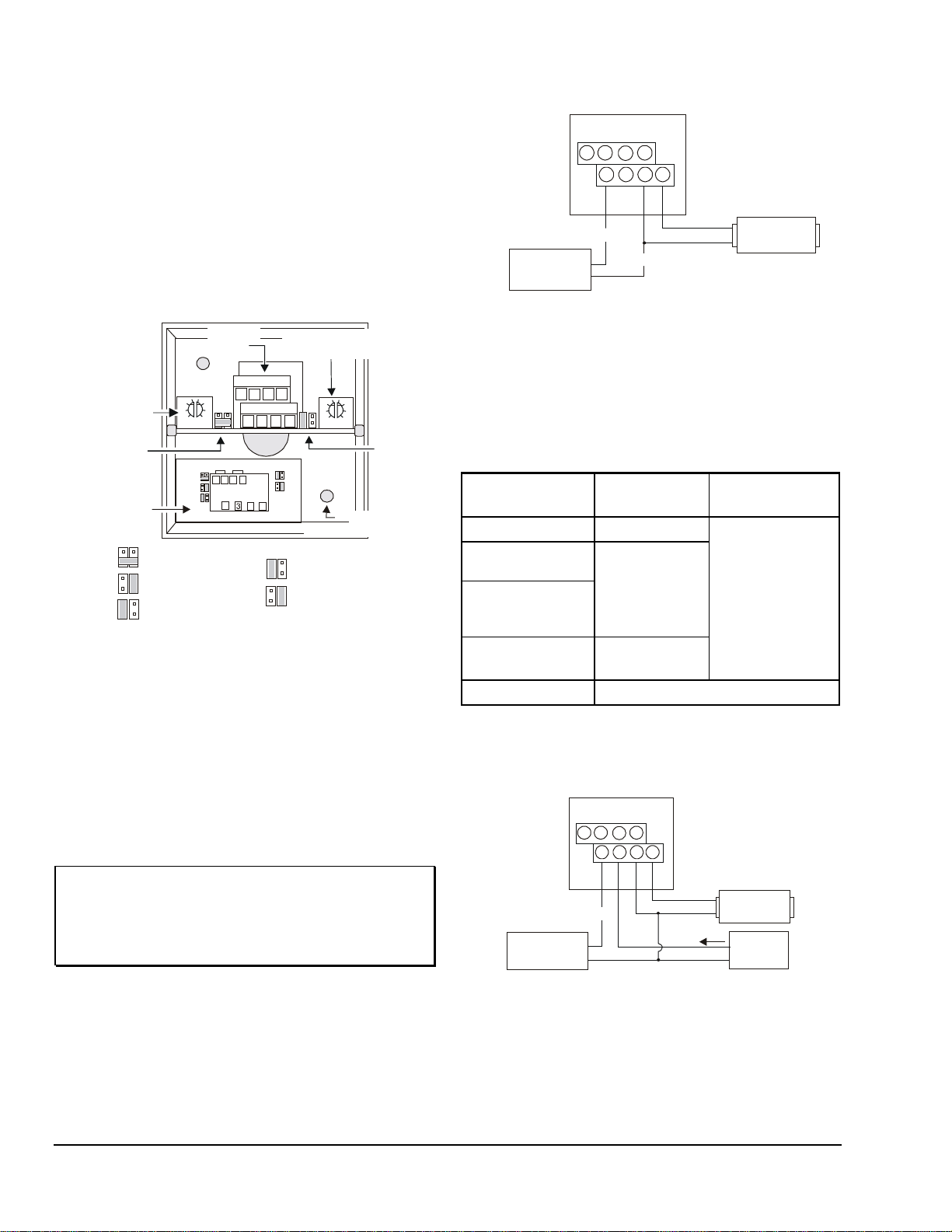
The multi-function humidity device must be configured
prior to installation for the following: input and output
signals and setpoint and proportional band.
The HL-67N5-8N00P has a setpoint potentiometer
(adjustable from 60 to 95% Relative Humidity [RH]) and
a proportional band potentiometer (adjustable from 5 to
30% RH). Refer to Figure 1 to change the setpoint or
proportional band for the application desired.
Figure 2: HL-67N5-8N00P as a Standalone Device
b. If the HL-67x5 is used as a proportional
override device, refer to Table 1 for jumper
positions.
Table 1: Jumper Positions with
HL-67N5-8N00P Used as a
Proportional Override Device
1. Use a 1/8 in. (3 mm) flat-blade screwdriver to
2. Adjust the proportional band potentiometer to the
Note: Setpoint minus proportional band is the highest
IMPORTANT: Set the proportional band to the
3. Select the appropriate input and output jumpers for
2 TRUERH Series HL-67x5 Multi-function Humidity Device with Temperature Sensor Installation Instructions
Figure 1: Internal View of the HL-67N5-8N00P
adjust the setpoint potentiometer to the humidity
level where the humidification equipment is
completely off.
desired range of humidity below the setpoint.
duct humidity reading at which the HL-67x5 will
allow the humidity equipment to be fully on.
highest number to reduce excessive
cycling of the humidification
equipment for optimum system
the application.
a. If the HL-67N5 is used as a standalone device
as shown in Figure 2, set the input jumper for
no input. Set the output jumper for the type of
signal the humidifier receives. (See Figure 1.)
performance without oscillation.
System
Air Handling Unit
DX-9xxx or
Input Jumper
Output Jumper
0 to 20 mA User selectable
0 to 10 VDC
(See Figure 1.)
Digital Control
Module via an
System 350 with a
W351P
Generic
0 to 20 mA or
0 to 10 VDC
User selectable
Figure 3 shows a typical proportional override
application for the HL-67x5. The relay output cannot be
used in this application.
Figure 3: HL-67N5-8N00P Using a System Controller

ounting
Housing
Conduit Hole
Snap-on Cover
Conduit Knockout
(Top and Bott om
of Cover)
Duct
Washer (Cup ped Side
Toward Housing)
Conduit Fitting
(Not Provided)
Nut for Conduit Fitting
(Not Provided)
No. 8
Screw
(2)
!
5
7
8
M
To mount the humidity device, refer to Figure 4, and
proceed as follows:
Figure 4: Mounting and Assembly
1. Remove any excess insulation from the duct that
prevents the probe from extending a minimum of
3 in. (76 mm) into the air stream.
2. Use the hole saw to make a 1 in. (25.4 mm)
diameter hole in the duct for inserting the probe.
3. Pull the plastic cover off the housing.
4. Insert the probe into the duct, and mark the
location of the holes for the mounting screws.
5. Remove the unit, and drill a 1/8 in. (3 mm) hole for
each mounting screw.
iring
W
CAUTION: CAUTION: Risk of Electric
Shock.
Disconnect the power supply
before making electrical
connections to avoid electric
shock.
MISE EN GARDE: Risque de décharge électrique.
Débrancher l'alimentation avant
de réaliser tout raccordement
électrique afin d'éviter tout
risque de décharge électrique.
Observe the following when wiring the unit:
• Do not run low voltage wiring in the same conduit
as line voltage wiring or other conductors that
supply highly inductive loads.
• Use 18 or 24 AWG wire.
• Make all wiring connections in accordance with the
National Electrical Code and local regulations.
To wire the device:
1. Route the wires from the controller to the
HL-67N5-8N00P through the conduit hole in the
housing. (Refer to Table 2 for wiring terminal
details.)
Table 2: Wiring Information
IMPORTANT: Remove the unit before drilling to
prevent any metal remnants from
falling onto the circuit board.
Seal any holes created during
installation to help reduce drafts and
ensure accurate sensor readings.
6. Use a gasket, sealer, or other means to seal the
area around the 1 in. (2.54 mm) hole between the
unit and the duct.
7. Reinsert the probe, and secure the housing to the
duct using the two No. 8 screws provided.
TRUERH Series HL-67x5 Multi-function Humidity Device with Temperature Sensor Installation Instructions 3
Terminal Terminal
Designation
1
2
3
4
6
Power + From the system
Common - For power, input,
Input + 0 to 20 mA or
Output + To humidification
Temperature N/A 1,000 ohm nickel
Relay N/A For on/off
Polarity Source/
Destination
controller or a
separate 24 VAC
transformer
and output
0 to 10 VDC from
the system
controller
equipment
temperature sensor
humidity equipment

2. Break out the plastic knockout on the cover
Note: X is either 10 VDC or 20 mA, depending on the application.
Setpoint - Measured RH
Proportiona l Band
HL-67N5’s Output Signal = X
(shown in Figure 4) with pliers to accommodate
the wiring or conduit.
Gradually raise the setpoint and monitor the
results. (Make sure the setpoint is not too high, or
excess moisture could collect in the duct.)
IMPORTANT: If using a conduit fitting
(not provided), use the washer
provided to support the fitting in the
housing. If the washer is not used,
the fitting could stress the plastic
housing.
3. Make wire connections to the appropriate screw
terminals. (See Table 2.)
4. Press the cover onto the base.
IMPORTANT: Check all connections before
applying power to the system.
Short-circuited or misconnected
wires could permanently damage
the unit.
roubleshooting
T
If the humidity device is not functioning properly:
1. Make sure the power supply is functioning and
wired properly to the HL-67N5-8N00P. Check the
output wiring connections.
5. Verify that the system controller operates properly.
Refer to the appropriate controller documentation.
6. If the HL-67N5-8N00P’s output is still inaccurate
after performing Steps 4 and 5, record the
proportional band setting and proceed as follows:
a. Measure duct humidity with a humidity
measuring device, such as an optical dew
point hygrometer, and record the result.
b. Measure the output of the HL-67N5-8N00P
using a Digital Volt Meter (DVM) or a
Milliampere (mA) meter, and record the result.
c. Measure the system controller’s output
(input to the HL-67N5-8N00P), using the DVM
or the mA meter, and record the result.
Notes: If the duct humidity is below the proportional
band, the HL-67N5-8N00P’s output should be
equal to the system controller’s output. If the
duct humidity is above the proportional band,
the HL-67x5’s output should be 0 VDC (0 mA).
If the duct humidity is inside the proportional
band, calculate the HL-67x5’s output as
follows:
2. If the HL-67N5-8N00P is not delivering an output,
check the jumper positions and make sure they
are appropriately selected for the application.
(Refer to Figure 1.)
3. If the humidification equipment is cycling
excessively, the proportional band setting may be
too low. Set the proportional band potentiometer to
a higher value. (See Figure 1.)
4. If room humidity never reaches the desired level,
the HL-67N5-8N00P’s setpoint may be set too low.
dditional Information
A
There are no accessories for the HL-67N5-8N00P.
See Table 3 for product specifications.
4 TRUERH Series HL-67x5 Multi-function Humidity Device with Temperature Sensor Installation Instructions

Table 3: Specifications
Output Load
Voltage: ≥ 1,000 ohm Current: ≤ 500 ohms
Conditions
Ambient Storage Conditions
-40 to 150°F (-40 to 66°C); 0 to 100% RH; 90°F (32°C) maximum dew point
European Single Point of Contact:
NA/SA Single Point of Contact:
APAC Single Point of Contact:
JOHNSON CONTROLS
JOHNSON CONTROLS
JOHNSON CONTROLS
Building Efficiency
All other marks herein are the marks of their respective owners. © 2016 Johnson Controls, Inc.
Product
Power Requirements
Wire Gauge
Humidity
Temperature Sensor
Controller Signal
Input Impedance
Relay Contact
Relay Contact Rating
Ambient Operating
Materials
Dimensions (H x W x D)
Shipping Weight
Agency Compliance
The performance specificati ons are nominal and conform to acceptable industry standards. For application at condi tions beyond these
specifications, consult the local Johnson Controls office. Johnson Control s, Inc. shall not be liable f or damages resulting from misapplication
or misuse of its products .
HL-67N5-8N00P Multi-function Humidity Device with Temperature Sensor
Proportional Output: 20 to 30 VAC, 1.1 VA at 50/60 Hz or 14 to 30 VDC at 22 mA
Relay Output: 20 to 30 VAC, 1.1 VA at 50/60 Hz or 20 to 30 VDC at 22 mA
16 to 24 AWG (18 AWG is recommended)
Element: All-Polymer
Setpoint: Adjustable from 60 to 95% RH
Proportional Band: Adjustable from 5 to 30% RH
Type: Thin-film nickel
Resistance: 1,000 ohm at 70°F (21°C)
Accuracy: ±0.34°F (0.18°C) at 70°F (21°C)
Coefficient: Approximately +3 ohms/°F; 5 ohms/°C
Input and Output: 0 to 10 VDC or 0 to 20 mA
Voltage: 20,000 ohms Current: 500 ohms
Single-Pole, Single-Throw (SPST), Normally Open — Open at setpoint and closed at
setpoint minus proportional band, standalone operation only
Maximum: 4A, 24 VAC, Class 2; Pilot Duty, 42.4 VA at 24 VAC;
Minimum: 100 mA at 5 VDC
32 to 150°F (0 to 66°C); 0 to 100% RH non-condensing; 90°F (32°C) maximum dew point
Light gray plastic cover with dark gray housing and probe
3.28 x 3.25 x 8.27 in. (83 x 83 x 210 mm) Probe (L x D): 6.25 x 0.98 in. (159 x 25 mm)
0.7 lb (0.03 kg)
UL Listed, File E107041, CCN PAZX, UL916
cUL Listed, File E107041, CCN PAZX7, CSA C22.2 No. 205-M1983
Duct Probe Material: 94-5V flammability rated per UL 94
WESTENDHOF 3
45143 ESSEN
GERMANY
507 E MICHIGAN ST
MILWAUKEE WI 53202
USA
Metasys® and Johnson Controls® are registered trademarks of Johnson Controls, Inc.
TRUERH Series HL-67x5 Multi-function Humidity Device with Temperature Sensor Installation Instructions 5
C/O CONTROLS PRODUCT
MANAGEMENT
NO. 22 BLOCK D NEW DISTRICT
WUXI JIANGSU PROVINCE 2 14142
CHINA
507 E. Michigan Street, Milwaukee, WI 53202
 Loading...