

Johnson Controls HIC2018B21S, HIC2024B21S, YIC2018B21S, YIC2024B21S, CIC2024B21S Installation And Maintenance Manual
...
Installation
and
Maintenance
Manual
INVERTER-DRIVEN
MULTI-SPLIT SYSTEM
HEAT PUMP
AIR CONDITIONERS
Type Model
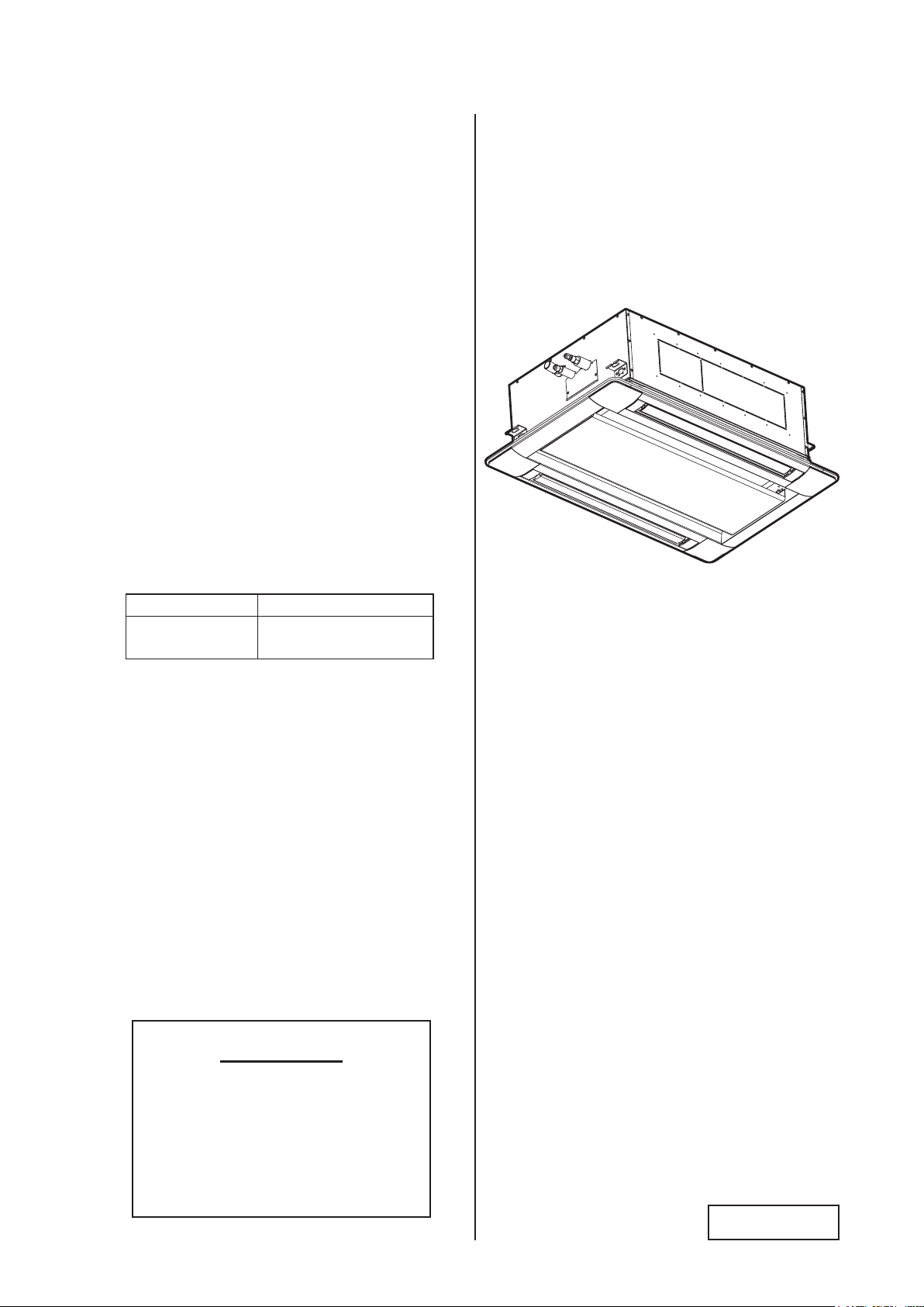
2-Way Cassette
(H,Y,C)IC2018B21S
(H,Y,C)IC2024B21S
IMPORTANT:
READ AND UNDERSTAND
THIS MANUAL BEFORE
INSTALLING THIS HEAT
PUMP AIR CONDITIONER.
KEEP THIS MANUAL FOR
FUTURE REFERENCE.
P5417050

ATTENTION
Each model number and all matching model numbers within a system must have
the same version of software.
Follow these steps to verify that your product model numbers have the same
version of software.
• Access the main printed circuit board in each product.
• Locate a white sticker with a P-XXXX number or
• Connect a service checker and locate the ROM number.
For further assistance, please contact our Technical Support Center at 1 (844)
873-4445 and select Option 2.
Important Notice
● Johnson Controls, Inc. pursues a policy of continuing improvement in design and performance in its
products. As such, Johnson Controls reserves the right to make changes at any time without prior
notice.
● Johnson Controls cannot anticipate every possible circumstance that might involve a potential hazard.
● This heat pump air conditioning unit is designed for standard air conditioning applications only. Do
not use this unit for anything other than the purposes for which it was intended.
● The installer and system specialist shall safeguard against leakage in accordance with local
pipetter and electrical codes. The following standards may be applicable, if local regulations are
not available. International Organization for Standardization: (ISO 5149 or European Standard, EN
378). No part of this manual may be reproduced in any way without the expressed written consent of
Johnson Controls.
● This heat pump air conditioning unit is operated and serviced in the United States of America and
comes with a full complement of the appropriate Safety, Dangers, Cautions, and Warnings.
● If you have questions, please contact your distributor or dealer.
● This manual provides common descriptions, basic and advanced information to maintain and service
this heat pump air conditioning unit which you operate as well for other models.
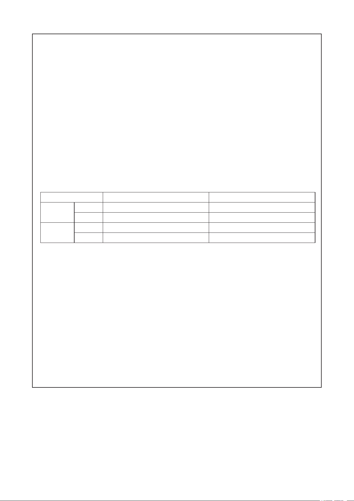
● This heat pump air conditioning unit has been designed for a specic temperature range. For optimum
performance and long life, operate this unit within the range limits according to the table below.
Temperature
Maximum Minimum
Cooling
Operation
Heating
Operation
DB: Dry Bulb, WB: Wet Bulb
* The temperature may change depending on the outdoor unit.
Indoor 89
Outdoor 118
Indoor 80
Outdoor 59
o
F DB/73oF WB (32oC DB/23oC WB) 69oF DB/59oF WB (21oC DB/15oC WB)
o
F DB (48oC DB) * 14oF DB (-10oC DB) *
o
F DB (27oC DB) 59oF DB ( 15oC DB)
o
F WB (15oC WB) * -4oF WB (-20oC WB) *
● This manual should be considered as a permanent part of the air conditioning equipment and should
remain with the air conditioning equipment.
Product Inspection upon Arrival
1. Upon receiving this product, inspect it for any damages incurred in transit. Claims for damage, either
apparent or concealed, should be led immediately with the shipping company.
2. Check the model number, electrical characteristics (power supply, voltage, and frequency rating),
and any accessories to determine if they agree with the purchase order.
3. The standard utilization for this unit is explained in these instructions. Use of this equipment for
purposes other than what it is designed for is not recommended.
4. Please contact your local agent or contractor as any issues involving installation, performance, or
maintenance arise. Liability does not cover defects originating from unauthorized modications
performed by a customer without the written consent of Johnson Controls, Inc. Performing any
mechanical alterations on this product without the consent of the manufacturer will render your
warranty null and void.
P5417050-rev.1
i

TABLE OF CONTENTS
1. Introduction ........................................................................................................................................................... 1
2. Safety Instructions ................................................................................................................................................ 1
3. Before Installation ................................................................................................................................................. 8
3.1 Combinations of Outdoor Units and Indoor Units ......................................................................................... 8
3.2 Transportation and Handling ........................................................................................................................ 8
3.3 Factory-Supplied Accessories ...................................................................................................................... 8
4. Installation Location .............................................................................................................................................. 9
5. Installation Work ..................................................................................................................................................11
5.1 Opening of False Ceiling and Location of Suspension Bolts .......................................................................11
5.2 Installing Suspension Bolts .........................................................................................................................11
5.3 Working Procedures ................................................................................................................................... 12
5.4 Installation of Decorative Panel .................................................................................................................. 15
6. Refrigerant Piping Work ...................................................................................................................................... 16
6.1 Piping Materials .......................................................................................................................................... 16
6.2 Piping Connection ...................................................................................................................................... 16
7. Condensate Piping .............................................................................................................................................. 18
8. Electrical Wiring .................................................................................................................................................. 22
8.1 General Check ........................................................................................................................................... 22
8.2 Electrical Wiring Capacity ........................................................................................................................... 22
8.2.1 Field Minimum Wire Sizes for Power Supply .................................................................................... 22
8.2.2 Details of Electrical Wiring Connection ............................................................................................. 23
8.3 Position of Electrical Wiring Connection ..................................................................................................... 24
8.4 Wired Controller Cable ............................................................................................................................... 27
8.4.1 Cautions for Individual Louver Settings ............................................................................................ 27
8.4.2 Cautions for Decorative Panel with Motion Sensor Kit (SOR-NED) ................................................. 28
8.4.3 Caution for Electrical Wiring ............................................................................................................. 29
8.5 Wiring Connections .................................................................................................................................... 30
8.6 DIP Switch Settings .................................................................................................................................... 31
8.7 High Speed Setting .................................................................................................................................... 33
8.8 Circulation Function at Heating Thermo-OFF* ........................................................................................... 33
8.9 Individual Louver Settings (Number of Louver Outlets) .............................................................................. 33
8.10 Control of Dew Condensation Prevention .................................................................................................. 34
8.11 Function Selection by Wired Controller ...................................................................................................... 35
8.12 Setback Operation ...................................................................................................................................... 37
9. Test Run .............................................................................................................................................................. 38
9.1 Before Test Run .......................................................................................................................................... 38
9.2 Test Run ..................................................................................................................................................... 38
9.3 Alarm Code ................................................................................................................................................ 42
ii
P5417050-rev.1

1. Introduction
Read following sections carefully before installing this product.
Read over the "Installation and Maintenance Manual" for the outdoor unit as well.
Forward this information, and the warranty to all installers and users.
Ask end users to maintain copies for future reference.
(Refrigerant Piping Work) (Electrical Wiring Work) (Ref. Charge Work) (Test Run) (User)
● For details on wiring between the indoor unit and the outdoor unit, refer to the "Installation and Maintenance
Manual" for the outdoor unit.
● For details on the optional decorative panel, refer to the "Installation and Maintenance Manual" for the
optional decorative panel.
● For details on the optional controller, refer to the "Installation and Maintenance Manual" for that optional
controller module.
● For details on each optional part, refer to the "Installation and Maintenance Manual" for each optional part.
● For the central controller, refer to the "Installation and Maintenance Manual" for the central controller.
2. Safety Instructions
Signal Words
Indicates a hazardous situation that, if not avoided, could result in death
or serious injury.
Indicates a hazardous situation that, if not avoided, could result in minor or
moderate injury.
Indicates information considered important, but not hazard-related (for
example, messages relating to property damage).
General Precautions
To reduce the risk of serious injury or death, read these instructions
● This system should be installed by personnel certied by Johnson Controls, Inc. Personnel must be
qualied according to local, state and national building and safety codes and regulations. Incorrect
installation could cause leaks, electric shock, re or explosion. In areas where Seismic Performance
requirements are specied, the appropriate measures should be taken during installation to guard
against possible damage or injury that might occur in an earthquake if the unit is not installed
correctly, injuries may occur due to a falling unit. Suspend pipes at certain points and reinforce
against earthquakes so that they will not be damaged by an external force. Check local codes and
regulations.
● Use appropriate Personal Protective Equipment (PPE), such as gloves and protective goggles and,
where appropriate, have a gas mask nearby. Also use electrical protection equipment and tools suited
for electrical operation purposes. Keep a wet cloth and a re extinguisher nearby during brazing. Use
care in handling, rigging, and setting of bulky equipment.
● When transporting, be careful when picking up, moving and mounting these units. Although the
unit may be packed using plastic straps, do not use them for transporting the unit from one location
to another. Do not stand on, or put any material on, the unit. Get a partner to help, and bend with
thoroughly and follow all warnings or cautions included in all manuals
that accompanied the product and are attached to the unit. Refer back to
these safety instructions as needed.
P5417050-rev.1
1

your knees when lifting to reduce strain on your back. Sharp edges or thin aluminum ns on the air
conditioner can cut ngers, so wear protective gloves.
● Do not touch or adjust any safety devices inside the indoor or outdoor units. All safety features,
disengagement, and interlocks must be in place and functioning correctly before the equipment is put
into operation. If these devices are improperly adjusted or tampered with in any way, a serious accident
can occur. Never bypass or jump-out any safety device or switch.
● Before servicing, turn-OFF the power supply and use accepted lockout and tag out procedures at all
main switches.
● This unit is a pressurized system. Never loosen threaded joints while the system is under pressure and
never open pressurized system parts.
● Johnson Controls will not assume any liability for injuries or damage caused by not following steps
outlined or described in this manual. Unauthorized modications to Johnson Controls' products are
prohibited as they…
◦ May create hazards that could result in death, serious injury or equipment damage
◦ Will void product warranties
◦ May invalidate product regulatory certications
◦ May violate OSHA standards
Take the following precautions to reduce the risk of property damage.
● Be careful that moisture, dust, or variant refrigerant compounds not enter the refrigerant system
during installation work. Foreign matter could damage internal components or cause blockages.
● If air lters are required on this unit, do not operate the unit without the air lter set in place. If the air
lter is not installed, dust may accumulate and breakdown may result.
● Do not install this unit in any place where silicon gases can coalesce. If the silicon gas molecules
attach themselves to the surface of the heat exchanger, the nned surfaces repel water. As a result,
any amount of drainage moisture condensate can overow from the condensate pan and could run
inside of the electrical box, possibly causing electrical failures.
● When installing the unit in a hospital or other facility where electromagnetic waves are generated from
nearby medical and/or electronic devices, be prepared for noise and electromagnetic interference
(EMI). Do not install where the waves can directly radiate into the electrical box, controller cable,
or controller. Inverters, appliances, high-frequency medical equipment, and radio communications
equipment may cause the unit to malfunction. The operation of the unit may also adversely affect
these same devices. Install the unit at least 10 ft. (3m) away from such devices.
● When a wireless controller is used, locate at a distance of at least 3.3 ft. (1m) between the indoor unit
and electric lighting. Otherwise, the receiver part of the unit may have difculty receiving operation
commands.
● If the wired controller is installed in a location where electromagnetic radiation is generated, make
sure that the wired controller is shielded and cables are sleeved inside conduit tubing.
● If there is a source of electrical interference near the power source, install noise suppression
equipment (lter).
● Do not install the unit in any location where animals and plants can come into direct contact with the
outlet air stream. Exposure could adversely affect the animals and plants.
● Do not install the unit with any downward slope to the side of the drain adapter. If you do, you may
have condensate water owing back, which may cause leaks.
● Be sure the condensate hose discharges water properly. If connected incorrectly, it may cause leaks.
● Do not install the unit in any place where oil can seep onto the units, such as table or seating areas in
restaurants, and so forth. For these locations or social venues, use specialized units with oil-resistant
features built into them. In addition, use a specialized ceiling fan designed for restaurant use. These
specialized oil-resistant units can be ordered for such applications. However, in places where large
quantities of oil can splash onto the unit, such as a factory, even the specialized units cannot be used.
These products should not be installed in such locations.
2
P5417050-rev.1

Installation Precautions
To reduce the risk of serious injury or death, the following installation
precautions must be followed.
● When installing the unit into…
▫ A wall: Make sure the wall is strong enough to hold the unit’s weight. It may be necessary to
construct a strong wood or metal frame to provide added support.
▫ A room: Properly insulate any refrigerant tubing run inside a room to prevent “sweating” that can
cause dripping and water damage to wall and oors.
▫ Damp or uneven areas: Use a raised concrete pad or concrete blocks to provide a solid, level
foundation for the unit to prevent water damage and abnormal vibration.
▫ An area with high winds: Securely anchor the outdoor unit down with bolts and a metal frame.
Provide a suitable wind bafe.
▫ A snowy area: Install the outdoor unit on a raised platform that is higher than drifting snow. Provide
snow protection hood.
● Do not install the unit in the following places. Doing so can result in an explosion, re, deformation,
corrosion, or product failure.
▫ Explosive or ammable atmosphere
▫ Where a re, oil, steam or powder can directly enter the unit, such as nearby or above a kitchen
stove.
▫ Where oil (including machinery oil) may be present.
▫ Where corrosive gases such as chlorine, bromine, or sulde can accumulate, such as near a hot
tub or a hot spring.
▫ Where dense, salt-laden airow is heavy, such as in coastal regions.
▫ Where the air quality is of high acidity.
▫ Where harmful gases can be generated from decomposition.
● Do not install a decorative panel with a motion sensor in the following places. It may cause failure or
deterioration of the sensor.
▫ Ambient temperature changes drastically.
▫ Where excessive force or vibration is applied to the sensor.
▫ Where static electricity or electromagnetic waves may generate.
▫ Where interference of infrared light such as gasses or mist is in the detecting area.
▫ Where the lens for sensor is exposed in high temperature and humidity for a long time.
▫ Where uid and corrosive gas exist.
▫ Where light such as sunlight or direct light affect the sensor.
▫ Where hot air from a heater, or something similar directly affects the sensor.
▫ Where the airow bounces back to the sensor by hitting obstacles such as shelf or locker.
▫ Where blower devices such as a ceiling fan or ventilating fan affect the airow from the indoor unit.
▫ Where weather directly affects the surface of the sensor.
▫ Where the lens surface may smudge or be damaged from something like a dusty environment.
Detecting function decreases, if the lens sensor has smudges.
In this case, wipe off smudges using a cotton swab soaked with alcohol or a soft cloth. Isopropyl
alcohol is recommended. (When wiping off smudges on the lens sensor, do not apply excessive
force. If excessive force is applied, the resin lens may be damaged and this may cause
malfunctions such as misdetection or undetectable motion.)
● Do not position the condensate pipe for the indoor unit near any sanitary sewers where corrosive
gases may be present. If you do, toxic gases can seep into breathable air spaces and can cause
respiratory injuries. If the condensate pipe is installed incorrectly, water leakage and damage to the
ceiling, oor, furniture, or other possessions may result. If the condensate pipe becomes clogged,
water may drip from the indoor unit. Do not install the indoor unit where such dripping can cause
moisture damage such as uneven locations. Use a raised concrete pad or concrete blocks to provide
a solid, level foundation for the unit to prevent water damage and abnormal vibration.
● Before performing any brazing work, be sure that there are no ammable materials or open ames
nearby. Always purge piping with Nitrogen when brazing.
● Perform a test run to ensure normal operation. Safety guards, shields, barriers, covers, and protective
devices must be in place while the compressor/unit is operating. During the test run, keep ngers and
clothing away from any moving parts.
P5417050-rev.1
3

● Clean up the site when nished, remembering to check that no metal scraps or bits of wiring have
been left inside the unit being installed.
After installation work for the system has been completed, explain the “Safety Precautions,” the proper use
and maintenance of this unit to the customer according to the information in all manuals that came with the
system. All manuals and warranty information must be given to the user or left near the indoor unit.
Refrigerant Precautions
To reduce the risk of serious injury or death, the following refrigerant
precautions must be followed.
● As originally manufactured, this unit contains refrigerant installed by Johnson Controls. Johnson
Controls uses only refrigerants that have been approved for use in the unit’s intended home country
or market. Johnson Controls' distributors similarly are only authorized to provide refrigerants that
have been approved for use in the countries or markets they serve. The refrigerant used in this unit
is identied on the unit’s faceplate and/or in the associated manuals. Any additions of refrigerant into
this unit must comply with the country’s requirements with regard to refrigerant use and should be
obtained from Johnson Controls' distributors. Use of any non-approved refrigerant substitutes will void
the warranty and will increase the potential risk of injury or death.
● If installed in a small room, take measures to prevent the refrigerant from exceeding the maximum
allowable concentration in the event that refrigerant gases should escape. The installation should
meet the requirements in ASHRAE Standards 15 and 34. If refrigerant gas has leaked during the
installation work, ventilate the room immediately.
● Check the design pressure for this product is 601 psi (4.15MPa). The pressure of the refrigerant
R410A is 1.4 times higher than that of the refrigerant R22. Therefore, the refrigerant piping for
R410A shall be thicker than that for R22. Make sure to use the specied refrigerant piping. If not, the
refrigerant piping may rupture due to an excessive refrigerant pressure. Besides, pay attention to
the piping thickness when using copper refrigerant piping. The thickness of copper refrigerant piping
differs depending on its material.
● The refrigerant R410A is adopted. The refrigerant oil tends to be affected by foreign matters such
as moisture, oxide lm, (or fat). Perform the installation work with care to prevent moisture, dust, or
different refrigerant from entering the refrigerant cycle. Foreign matter can be introduced into the cycle
from such parts as expansion valve and the operation may be unavailable.
● To avoid the possibility of different refrigerant or refrigerant oil being introduced into the cycle, the
sizes of the charging connections have been changed from R407C type and R22 type. It is necessary
to prepare the following tools listed in Section 3 before performing the installation work. Use
refrigerant pipes and joints that are approved for use with R410A.
● Before installation is complete, make sure that the refrigerant leak test has been performed. If
refrigerant gases escape into the air, turn OFF the main switch, extinguish any open ames and
contact your service contractor. Refrigerant (uorocarbon) for this unit is odorless. If the refrigerant
should leak and come into contact with open ames, toxic gas could be generated. Also, because the
uorocarbons are heavier than air, they settle to the oor, which could cause asphyxiation.
● When installing the unit, and connecting refrigerant piping, keep all piping runs as short as possible,
and make sure to securely connect the refrigerant piping before the compressor starts operating. If
the refrigerant piping is not connected, and the compressor activates with the stop valve opened, the
refrigerant system is subjected to extremely high pressure, which can cause an explosion or re.
● Tighten the are nut with a torque wrench in the specied manner. Do not apply excessive force to the
are nut when tightening. If you do, the are nut can crack and refrigerant leakage may occur.
4
P5417050-rev.1

● A compressor/unit comprises a pressurized system. Never loosen threaded joints while the
system is under pressure and never open pressurized system parts.
● When maintaining, relocating, or disposing of the unit, dismantle the refrigerant piping after the
compressor stops.
● When pipes are removed from under the piping cover, after the insulation work is completed,
cover the gap between the piping cover and pipes using a packing (eld-supplied). If the gap is
not covered, the unit may be damaged if snow, rain water or small animals enter the unit.
● Do not apply an excessive force to the stop valve at the end of opening. Otherwise, the stop
valve ies out due to refrigerant pressure. At the test run, fully open the gas and liquid valves.
Otherwise, these devices become damaged. (It is closed before shipment.)
● If the arrangement for outdoor units is incorrect, it may cause owback of the refrigerant and
result in failure of the outdoor unit.
● The refrigerant system may be damaged if the slope of the piping connection kit exceeds +15
Electrical Precautions
o
.
Take the following precautions to reduce the risk of electric shock, re
or explosion resulting in serious injury or death.
● Highly dangerous electrical voltages are used in this system. Carefully refer to the wiring diagram
and these instructions when wiring. Improper connections and inadequate grounding can cause
serious injury or death.
● Perform all electrical work in strict accordance with this manual and all relevant regulatory
standards.
● Do not open the service cover or access panel to indoor or outdoor units without turning OFF
the main power supply. Before servicing, open and tag all disconnect switches. Never assume
electrical power is disconnected. Check with a meter and equipment.
● Only use electrical protection equipment and tools suited for this installation.
● Use specied cables between units.
● Do not run the relay wiring for the motion sensor and power supply wiring in parallel.
Electromagnetic Interference (EMI) may cause malfunction of the sensor.
● Communication cable shall be a minimum of AWG18 (0.82mm
2
), 2-Conductor, Stranded Copper.
Shielded cable must be considered for applications and routing in areas of high EMI and other
sources of potentially excessive electrical noise to reduce the potential for communication errors.
When shielded cable is applied, proper bonding and termination of the cable shield is required
as per Johnson Controls guidelines. Plenum and riser ratings for communication cables must be
considered per application and local code requirements.
● Use an exclusive power supply for the air conditioner at the unit’s rated voltage.
● Be sure to install circuit breakers (ground fault interrupter, isolating switch, molded case circuit
breaker and so on), with the specied capacity. Ensure that the wiring terminals are tightened
securely to recommended torque specications. If a circuit breaker or fuse is frequently activated,
shut down the system and contact your service contractor.
● The polarity of the input terminals is important, so be sure to match the polarity when using
contacts that have polarity.
● Before installing the controller or remote devices, ensure the indoor and outdoor unit operation has
been stopped. Further, be sure to wait at least ve minutes before turning OFF the main power
switch to the indoor or outdoor units. Otherwise, water leakage or electrical breakdown may result.
● Clamp electrical wires securely with a cable band after all wiring is connected to the terminal block.
In addition, run wires securely through the wiring access channel.
P5417050-rev.1
5

● When installing the power lines, do not apply tension to the cables. Secure the suspended cables at
regular intervals, but not too tightly.
● Make sure that the terminals do not come into contact with the surface of the electrical box. If the
terminals are too close to the surface, it may lead to failures at the terminal connection.
● Turn OFF and disconnect the unit from the power supply when handling the service connector. Do
not open the service cover or access panel to the indoor or outdoor units without turning OFF the
main power supply.
● After stopping operation, be sure to wait at least ve minutes before turning off the main power
switch. Otherwise, water leakage or electrical breakdown may result. Disconnect the power supply
completely before attempting any maintenance for electrical parts. Conrm that no residual voltage is
present after disconnecting the power supply.
● Do not clean with, or pour water into, the controller as it could cause electric shock and/or damage
the unit. Do not use strong detergent such as a solvent. Clean with a soft cloth.
● Check that the ground wiring is securely connected. Do not connect ground wiring to gas piping,
water piping, lighting conductor, or telephone ground wiring.
● If a circuit breaker or fuse is frequently activated, shut down the system and contact your service
contractor.
● This equipment can be installed with a Ground Fault Circuit Breaker (GFCI), which is a recognized measure
for added protection to a properly grounded unit. Install appropriate sized breakers / fuses / overcurrent
protection switches, and wiring in accordance with local, state and NEC codes and requirements. The
equipment installer is responsible for understanding and abiding by applicable codes and requirements.
6
P5417050-rev.1
● Proper handling of this unit requires two people. Safe handling and installation of the indoor unit requires
NOTICE
the strength of two people. Mounting the unit alone may cause injury due to a fall of the unit. Although the
unit may be girded with steel banding, do not use it for transportation. Avoid contact with nned surfaces
of the heat exchanger as sharp edges can cause severe injury to hands and ngers. Use appropriate
work gloves for the job.
● The optional decorative panel can become deformed if the positioning of the indoor unit's suspension
brackets are not stable or level. Condensation can accumulate in low spots as a result due to escaping
air through any resulting gaps between the indoor unit and the decorative panel.
● Check to ensure that the condensate hose discharges moisture properly. If connected incorrectly, it can
result in leakage and damage to property.
● Make sure to use the factory-supplied condensate hose and hose clamp. Other makes can cause
moisture leakage.
● Do not bend or twist the factory-supplied condensate hose. This could compromise the seal and result in
moisture leakage.
● Do not apply an excessive force to the condensate pipe connection. This can also compromise the seal
properties of the connection.
● Verify that the installed unit is level with oor and ceiling surfaces. Any variance or inclination can cause
moisture to back up into the condensate pan, overow, and seepage onto ceiling or wall surfaces, and
cause damage to carpeted surfaces or furniture below.
● Do not install this system in close proximity to septic sewer lines where ammable and toxic gases can coalesce.
● Inspect the condensate pan before the onset of winter to drain away all accumulated moisture in the pan.
● The heat exchanger of indoor units overheats whenever there is a slight amount of refrigerant circulating
during slowdown or stoppage. As a result, moisture in the condensate pan evaporates where it can affect
ceiling or wall surfaces.
● After the drain check is completed, insert the rubber plug again and seal the gap with a silicon sealant.
Electrical Installation
In some cases, the packaged air conditioner may not be operated normally under the following cases:
● When electrical power for the packaged air conditioner is supplied from the same power transformer
as the external equipment.
● When the power supply wiring for the external equipment and the packaged air conditioner are
located close to each other.
Regarding that mentioned above, surge voltage may be inducted into the power supply wiring for the crated
unit due to a spike in power consumption for this device and an activation of the switch. Check the eld
regulations and standards before performing any electrical work in order to safeguard the power supply for
the crated air conditioner unit.
P5417050-rev.1
7

3. Before Installation
Unit: inch (mm)
3.1 Combinations of Outdoor Units and Indoor Units
The combination capacity of an indoor unit against an outdoor unit is selected depending on the outdoor
unit capacity. Refer to the "Installation and Maintenance Manual" for the outdoor unit to decide the required
combination of indoor and outdoor units, and the combination unit capacity.
3.2 Transportation and Handling
1. Transport the product as close to the installation location as possible before unpacking.
2. Do not lay any objects on the indoor unit.
3. The indoor unit comes crated upside-down with the foam polystyrene condensate pan positioned on
top.
Do not invert the unit until it is ready to be suspended above the oor. Inverting the unit while on the
oor will crush the condensate pan. Do not handle the unit by grabbing at the polystyrene pan and
other air outlets as they are fragile and will sustain damage.
4. The indoor unit handle is fabricated from foam polystyrene and is susceptible to breakage if any
excessive force is applied as a result of mishandling of the unit during installation.
3.3 Factory-Supplied Accessories
1. Check to ensure that the following accessories are packed with the indoor unit.
The screws, washers, and are nuts are packed in the pipe insulation.
Accessory
Checking Scale
(Cut and Take Out it from Carton Board)
Cross Recessed
Head Screws (M6)
Washer with Insulation
Material (M10)
Washer (M10)
Condensate Hose
Hose Clamp
Pipe Insulation
Pipe Insulation
Cable Band
Cable Band
Insulation
3/16T x 1-15/16 x 7-7/8 (5T x 50 x 200)
Insulation
3/16T x 10-5/8 x 10-5/8 (5T x 270 x 270 )
Qty.
For Adjusting Space of False Ceiling Opening
1
and Position of Unit
4
For Fitting Paper Pattern
4
For Unit Installation
4
1
For Condensate Pipe Connection
1
1
For Refrigerant Piping Connection
1
2
For Securing Wired Controller Cable,
Louver Sensor and Insulation of Piping
6
1
For Covering Wiring Connection
For Covering Condensate Connection
1
Purpose
8
P5417050-rev.1

Single Unit Installation
Multipul Unit Installation
Min. 3-15/16 (100)
Min. 59-1/16 (1500)
Min. 94-1/2 (2400)
(Piping Connection Side)
NOTICE
The decorative panel, controller, and branch piping are optional accessories and are not included with the
indoor unit. If necessary, please contact your contractor.
2. Do not insert or leave any foreign objects inside the indoor unit and verify that no foreign objects
remain inside the indoor unit before installation and the test run. Failure to do this can result in
equipment failure and damage to the unit.
3. Necessary Tools and Instrument List for Installation
No. Tool No. Tool
1 Handsaw 11 Wrench
2 Philips Screwdriver 12 Charging Cylinder
3 Vacuum Pump 13 Manifold Gauge
4 Refrigerant Gas Hose 14 Wire Cutter
5 Megohmmeter 15 Gas Leak Detector
6 Copper Pipe Bender 16 Level
7 Manual Water Pump 17 Clamp for Solderless Terminals
8 Copper Tube Cutter 18 Hoist (for Indoor Unit)
9 Brazing Kit 19 Ammeter
10 Hexagonal Wrench 20 Voltage Meter
4. Installation Location
1. Install the indoor unit at a proper distance from walls as shown below.
Service
Access
(500)
(500)
Panel
Min.
19-11/16
(500)
Piping
Connection
Side
Min.
3-15/16
(100)
Min.
Min.
Min.
3-15/16
(100)
Min.
Min.
19-11/16
19-11/16
NOTE:
Use tools and measuring
instruments (vacuum pump, gas
hose, charging cylinder, and
manifold gauge) exclusively for
the refrigerant R410A.
Unit: inch (mm)
Service
Access
(500)
(3000)
Panel
Min.
19-11/16
(500)
Service
Access
Panel
19-11/16
118-1/8
Min.
3-15/16
(100)
Min.
19-11/16
Piping
Connection
(500)
Side
Min.
19-11/16
(500)
Distance from Wall Side
2. Install the indoor unit with sufcient space around it for operation and maintenance access as shown below.
Do not leave combustible materials inside the service space of the indoor unit.
Unit: inch (mm)
Min.
94-1/2
Min. 59-1/16 (1500)
Min. 19-11/16 (500)
(2400)
Minimum Service Space
P5417050-rev.1
9

3. Select an installation location as follows:
(Unit Height in False Ceiling)
Gradient: 1/25 to 1/100
Unit: inch (mm)
• Minimum Space
Down slope gradient for condensate piping: 1/25 to 1/100
•
Install the indoor unit at least 10.2 ft (3.1m) above
oor level.
Minimum 3/8 (10)
Clearance
13-9/16 (345)
NOTE:
There must be sufcient structural integrity to support
the weight of the unit. The designated ceiling surface
Condensate Piping
area should allow for additional space for the optional
decorative panel installation. Do not install against any
Down Slope
sloped ceiling areas as the tilted axis will interfere with
the proper ow and disposal of moisture.
4. Consider the air distribution from the indoor unit to the space of the room, and select a suitable location
so that uniform air temperature in the room can be obtained.
5. Install the unit where there are no obstacles which can impede the return air and discharged air.
6. Do not install the unit near a door or a window where the indoor unit comes into contact with humid
outside air. Otherwise, condensation may occur.
7. In the event that temperature and humidity levels inside the ceiling exceed 86
o
F (30oC)/RH, relative
humidity 80%, apply additional insulation materials to the external surface of the indoor unit to avoid
condensation.
8. If installing the indoor unit to a high ceiling, the warmed air will remain near the ceiling during heating
operation. Thus, a parallel installation of a circulator is recommended.
9. Do not install the indoor unit where airow from the air outlet blows directly onto temperature detection
devices such an alarm device or a control device. It can result in false readings and an alarm failure.
10. When installing the IR receiver kit (optional) or the motion sensor (optional), refer to their respective
installation manuals.
11. The ceiling height of the indoor units can be increased when using High Speed Setting.
Refer to Section 8.7 "High Speed Setting".
10
P5417050-rev.1

5. Installation Work
(221 to 331 lbs)
Steel
(W3/8 or M10)
5-7/8 to 6-5/16 inches
Dimension of Opening :
Dimension of Suspension Bolts
M10 or W3/8 (Field-Supplied)
13/16
Unit: inch (mm)
5.1 Opening of False Ceiling and Location of Suspension Bolts
1. Determine the nal location and installation orientation of the indoor unit with respect to the space
allowed for piping, wiring, and maintenance access.
2. Then cut away the false ceiling area for the indoor unit installation and install suspension bolts.
3. The dimensions for an opening false ceiling and location of suspension bolts are as shown below.
(20)
13/16
26-3/8 (670)
(20)
13/16
(20)
Dimension of Suspension Bolts : b
:
21-1/4 (540)
4-Positions of Suspension Bolts
Dimension of Opening : a
41-3/4 (1060)
35-13/16 (910)
3-1/4 (83)
(Liquid Piping)
2-9/16 (65)
(Condensate Piping)
3 (76)
(Gas Piping)
4-1/2 x 1-1/4 Holes (For Suspension Bolt)
13/16
(20)
Wiring Connection Side
Piping Connection Side
Condensate Piping Connection Side
Decorative Panel
4. Ceiling work differs depending on the building structure. Consult with a building contractor or an interior
nishing worker for more information.
NOTE:
Do not install electric lighting in too close of a proximity to the unit as unit operation can cause the
lights to icker.
5.2 Installing Suspension Bolts
1. Reinforce the designated opening in the false ceiling area. Use approved materials of sufcient tensile
strength to allow for quality installation.
2. Strengthen suspension bolts with support plates as required in preparation for an earthquake. (Refer
to the Safety Section for more information.)
Use eld-supplied M10 suspension bolts and support plates.
For Wooden Beam For Concrete Slab
Install the indoor unit to the tie beam (for single-
storied building) or to the second oor girder (for
two-storied building), and use sufciently strong
squared timber as shown below.
Interval between Beams Squared Timber
< 35-7/16 (900) 2-3/8 (60) square
< 70-7/8 (1800) 3-9/16 (90) square
inch (mm)
Install suspension bolts so that it can withstand the
indoor unit weight load.
Insert
Concrete
Suspension Bolt
P5417050-rev.1
11
 Loading...