

Page 1

FX-PCV Programmable Variable Air
Volume Box Controllers Installation
Instructions
Applications
The FX-PCV1610/1620 controllers are part of the Facility Explorer® Series Programmable Controller
(FX-PC) family. FX-PCV controllers feature an integral 4 Nm damper actuator and Differential
Pressure Transducer. FX-PCV controllers run pre-engineered and user-programmed applications
required to monitor and operate a wide variety of VAV boxes.
The FX-PCV controllers operate on an RS-485 BACnet® MS/TP Bus as BACnet Application Specific
Controllers (B-ASCs) and integrate into the web-based Facility Explorer system.
North American Emissions Compliance
United States
This equipment has been tested and found to comply with the limits for a Class A digital device
pursuant to Part 15 of the FCC Rules. These limits are designed to provide reasonable protection
against harmful interference when this equipment is operated in a commercial environment.
This equipment generates, uses, and can radiate radio frequency energy and, if not installed
and used in accordance with the instruction manual, may cause harmful interference to
radio communications. Operation of this equipment in a residential area may cause harmful
interference, in which case the users will be required to correct the interference at their own
expense.
Canada
This Class (A) digital apparatus meets all the requirements of the Canadian Interference-Causing
Equipment Regulations.
Cet appareil numérique de la Classe (A) respecte toutes les exigences du Règlement sur le
matériel brouilleur du Canada.
Installation
Observe these guidelines when installing an FX-PCV controller:
• Transport the controller in the original container to minimize vibration and shock damage to the
FX-PCV Box controller.
• Do not drop the controller or subject it to physical shock.
Parts included
• One FX-PCV controller with removable bus and power terminal blocks
• One installation instructions sheet
Materials and special tools needed
• One screw or other type of fastener appropriate for the mounting surface
Part No. 24-10143-179 Rev. C
2019-03-22
*2410143179C*
(barcode for factory use only)
FX-PCV1610-0, FX-PCV1620-0
Page 2

• Several 6 mm (1/4 in.) female spade terminals for input and output wiring
• Small straight-blade screwdriver for securing wires in the terminal blocks
Mounting
Observe these guidelines when mounting an FX-PCV.
Important: When the air supply to the VAV box is below 10°C (50°F), make sure that any
condensation on the VAV box, particularly on the damper shaft, does not enter the FXPCV electronics. Mount the FX-PCV vertically above the damper shaft to allow any shaft
condensation to fall away from the FX-PCV. Additional measures may be required in some
installations.
• Ensure the mounting surface can support the controller and any user-supplied enclosure.
• Mount the controller on a hard, even surface whenever possible.
• Use shims or washers to mount the controller securely and evenly on the mounting surface.
• Mount the controller in an area free of corrosive vapors and observe the ambient conditions in
the Technical specifications section.
• Provide sufficient space around the controller for cable and wire connections and good
ventilation through the controller. Leave a minimum of 50 mm (2 in.) around the top, bottom,
sides, and front of the controller.
• Do not mount the controller on surfaces prone to vibration, such as duct work, or in areas
where electromagnetic emissions from other devices or wiring can interfere with controller
communication.
On panel or enclosure mount applications, observe these additional guidelines:
• Do not install the controller in an airtight enclosure.
• Mount the controller so that the enclosure walls do not obstruct cover removal or ventilation
through the controller.
• Mount the controller so that the power transformer and other devices do not radiate excessive
heat to the controller.
To mount the FX-PCV controller:
1. Place the controller in the proper mounting position on the damper shaft so that the wiring
connections are easily accessible. Make sure the controller base is parallel to the VAV box
(perpendicular to the damper shaft). If needed, use a spacer to offset tipping of the FX-PCV
controller caused by the shaft bushings.
2. Secure the self-drilling No. 10 screw through the FX-PCV controller mounting slot with a power
screwdriver and 100 mm (4 in.) extension socket. Otherwise, use a punch to mark the position
of the shoulder washer, and then drill a hole into the VAV box using a 3.5 mm (9/64 in.) drill bit.
Insert the mounting screw, and tighten against the washer.
Important: Do not overtighten the screws, or the threads may strip. If mounting to the
VAV box, make sure the screws do not interfere with damper blade movement.
3. Locate the damper position using the typical marking on the end of the damper shaft.
FX-PCV Programmable Variable Air Volume Box Controllers Installation Instructions2
Page 3

Figure 1: Typical damper end shaft Iocns
4. Note the direction, clockwise (CW) or counterclockwise (CCW), required to close the damper.
Grasp the damper shaft firmly with pliers and either manually close the damper (for 90° boxes)
or manually open the damper (for 45° or 60° boxes).
5. Push down and hold the Manual Override button (Figure 2), and turn the FX-PCV controller
coupler until it contacts the mechanical end-stop at either the fully closed (90° boxes) or fully
open (45° and 60° boxes) position.
6. If the damper for a 90° box closes CCW, rotate the coupler to the CCW mechanical limit. If the
damper for a 90° box closes CW, rotate the coupler to the CW mechanical limit. The open endstop is automatically set for 90° boxes. For 45° and 60° boxes, hard stops must be provided
at both fully closed and fully open damper positions. By installing the FX-PCV controller at the
fully open position, the FX-PCV controller provides the open stop for 45° and 60° boxes. The
closed damper seal provides the fully closed stop.
7. All models are compact in size and are easily installed on VariableAir Volume (VAV) boxes with a
round shaft up to 13 mm in diameter,or a 10 mm square shaft.Tighten the square coupler bolt
to the shaft using an 8 mm (5/16 in.) wrench or 10 mm (3/8 in.) 12-point socket. Tighten to 11
to 15 N·m (100 to 130 lb·in).
8. Loop the pneumatic tubing to include a trap for condensation. Attach the tubing from the FXPCV controller to the VAV box pickup. The HIGH (red) tubing is connected to the inlet or highpressure side and the clear tubing to the low side (Figure 2).
9. Push the manual release button, and turn the actuator coupling manually to ensure that the
actuator can rotate from fully closed to fully open positions without binding.
10. Complete the mounting by rotating the damper to the fully open position.
CAUTION
Risk of Property Damage
Rotate the damper to the full-open position before starting the air handler. Failure to rotate the damper
to the full-open position may result in damage to the VAV box or ductwork when the air handler is
started.
CAUTION
Mise En Garde: Risque de dégâts matériels
Faire pivoter le registre pour le placer en position d'ouverture complète avant de démarrer l'unité de
traitement d'air. Le non-respect de cette directive risque d'endommager le caisson de l'unité à volume
d'air variable (VAV) ou le réseau de conduites au démarrage de l'unité de traitement d'air.
3FX-PCV Programmable Variable Air Volume Box Controllers Installation Instructions
Page 4

Wiring diagram
Figure 2: FX-PCV Controller physical features and wiring terminations
Table 1: FX-PCV Controller physical features
Number Feature
1 Pneumatic tubing
2 Controller coupler
3 Coupler bolt
4 Manual override switch
5 Binary Outputs (24 VAC Triacs)
6 Configurable outputs can be defined as:
• Voltage Analog Output (0-10 VDC)
• Binary Output (24 VAC Triac)
7 24 VAC, Class 2 Supply Power Terminal Block
8 Anti-rotation slot
9 LED Status Indicators
10 FC Terminal Block
11 Sensor Port (SA Bus) RJ-12 6-Pin Modular Jack
12 SA Terminal Block
13 Sensor Port (SA Bus) RJ-12 6-Pin Modular Jack
FX-PCV Programmable Variable Air Volume Box Controllers Installation Instructions4
Page 5

Table 1: FX-PCV Controller physical features
Number Feature
14 Device Address DIP Switch Block
15 Universal Input can be defined as:
Voltage Analog Input (0-10 VDC)
• Resistive Analog Inputs (0-600k ohm)
• 0-2K Potentiometer
• RTD: 1k Nickle 1k Platinum or A99B SI
• NTC: 10k Type L 10k JCI Type II, or 2.252k Type II
Dry Contact Binary Input
Wiring
CAUTION
Risk of Electric Shock
Disconnect the power supply before making electrical connections to avoid electric shock.
CAUTION
Mise En Garde: Risque de décharge électrique
Débrancher l'alimentation avant de réaliser tout raccordement électrique afin d'éviter tout risque de
décharge électrique.
Important: Do not connect supply power to the controller before finishing wiring and
checking all wiring connections. Short circuits or improperly connected wires can result in
damage to the controller and void any warranty.
Important: Do not exceed the controller electrical ratings. Exceeding controller electrical
ratings can result in permanent damage to the controller and void any warranty.
Important: Use copper conductors only. Make all wiring in accordance with local, national,
and regional regulations.
Important: Electrostatic discharge can damage controller components. Use proper
electrostatic discharge precautions during installation, setup, and servicing to avoid damaging
the controller.
For detailed information on configuring and wiring an MS/TP Bus, FC bus, or SA bus, refer to the FX-
PC Series Controllers MS/TP Communications Bus Technical Bulletin (LIT-12011670).
FX-PCV terminals and bus ports
See Figure 2 for input and output terminal and bus port locations on the FX-PCV controller. Observe
the following guidelines when wiring an FX-PCV controller.
5FX-PCV Programmable Variable Air Volume Box Controllers Installation Instructions
Page 6

Input and Output terminals
The input spade terminals are located on the side of the FX-PCV near the device address switch. The
output spade terminals are located on the opposite side of the controller near the power supply
terminal block. See Table 2 for more information.
FC bus terminal block
The FC Bus terminal block is a blue, removable, 4-terminal plug that fits into a board-mounted jack.
Wire the removable FC Bus terminal block plugs on the FX-PCV and other field controllers in a daisychain configuration using 3-wire twisted, shielded cable as shown in Figure 3. See Table 5 for more
information.
Note: The Shield terminal (SHLD) on the FC Bus terminal block is isolated and can be used to
connect the cable shields on the bus (Figure 3).
Figure 3: FC bus terminal block wiring
SA bus terminal block
The SA Bus terminal block is a brown, removable, 4-terminal plug that fits into a board-mounted
jack.
Wire the removable SA Bus terminal block plugs on the FX-PCV and other SA Bus devices in a daisychain configuration using 4-wire twisted, shielded cable as shown in Figure 4. See Table 5 for more
information.
Figure 4: SA bus terminal block wiring
FX-PCV Programmable Variable Air Volume Box Controllers Installation Instructions6
Page 7

Sensor port
The Sensor (SA Bus) port on the left side of the FX-PCV (Figure 2) is an RJ-12, 6-position modular jack
that provides a connection for the VAV Balancing Tool, specified network sensors, or other SA Bus
devices with RJ-12 plugs.
The Sensor port is connected internally to the SA Bus terminal block. See Table 5 for more
information. The Sensor Port pin assignment is shown in Figure 5.
Figure 5: Pin number assignments for sensor, SA bus, and FC bus ports on FX-PCVs
Supply power terminal block
The 24 VAC supply power terminal block is a gray, removable, 3-terminal plug that fits into a boardmounted jack on the bottom right of the FX-PCV.
Wire the 24 VAC supply power wires from the transformer to the HOT and COM terminals on the
terminal plug as shown in Figure 6. The middle terminal on the supply power terminal block is not
used. See Table 5 for more information.
The supply power wire colors may be different on transformers from other manufacturers. Refer to
the transformer manufacturer’s instructions and the project installation drawings for wiring details.
Important: Connect 24 VAC supply power to the FX-PCV and all other network devices so that
transformer phasing is uniform across the network devices. Powering network devices with
uniform 24 VAC supply power phasing reduces noise, interference, and ground loop problems.
The FX-PCV does not require an earth ground connection.
Figure 6: 24 VAC supply power terminal block wiring
7FX-PCV Programmable Variable Air Volume Box Controllers Installation Instructions
Page 8

To wire the FX-PCV controller:
1. Terminate wiring per engineering drawings.
2. Wire network sensors and other devices to the FX-PCV'sSA Bus.
3. Wire the FC Bus in a daisy chain.
4. Ensure that the FX-PCV’s device address DIP switches are set to the appropriate device address.
(See Setting the device address.)
5. Connect the FX-PCV controller to 24 VAC, Class 2 power.
FX-PCV terminal functions, ratings, requirements, and wiring guidelines
Input and Output wiring guidelines
Table 2 provides information about the functions, ratings, and requirements for the FX-PCV input
and output terminals; and references guidelines for determining proper wire sizes and cable
lengths.
In addition to the wiring guidelines in Table 2, observe these guidelines when wiring FX-PCV inputs
and outputs:
• Run all low-voltage wiring and cables separate from high-voltage wiring.
• All input and output cables, regardless of wire size or number of wires, should consist of twisted,
insulated, and stranded copper wires.
• Shielded cable is not required for input or output cables.
• Shielded cable is recommended for input and output cables that are exposed to high
electromagnetic or radio frequency noise.
• Cable runs that are less than 30 m (100 ft) typically do not require an offset in the input/output
software setup. Cable runs that are over 30 m (100 ft) may require an offset in the input/output
software setup.
Input and Output wiring guidelines tables
Table 2: I/O terminal blocks, functions, ratings, requirements, and cables
Terminal block
label
UNIVERSAL
(Inputs)
Terminal
labels
+15 V 15 VDC Power Source for active (3-
Function, ratings, and
requirements
wire) input devices connected to the
Universal INn terminals.
Provides 100 mA total current.
To determine wire size
and maximum cable
length
Same as (Universal)
INn.
Note: Use 3-wire
cable for devices
that source power
from the +15 V
terminal.
FX-PCV Programmable Variable Air Volume Box Controllers Installation Instructions8
Page 9

Table 2: I/O terminal blocks, functions, ratings, requirements, and cables
Terminal block
label
Terminal
labels
INn
Function, ratings, and
requirements
Analog Input - Voltage Mode (0–10
VDC)
10 VDC maximum input voltage
Internal 75k ohm Pulldown
Analog Input - Resistive Mode (0–
600k ohm)
Internal 12 V, 15k ohm pull up
Qualified Sensors: 0–2k
potentiometer,
RTD (1k Nickel [Johnson Controls
sensor],
1k Platinum, and A99B Silicon
Temperature Sensor)
Negative Temperature Coefficient
(NTC) Sensor
To determine wire size
and maximum cable
length
See Guideline A in Table
3.
See Guideline A in Table
3.
BINARY
(Outputs)
10K Type L (10K JCI Type II is
equivalent to Type L) or 2.252K Type II
ICOMn Universal Input Common for all
Universal IN terminals
Note: All Universal ICOMn
terminals share a common,
which is isolated from all other
commons.
OUTn Binary Output - 24 VAC Triac
(Internal Power)
Sources internal 24 VAC power (24~
HOT)
Same as (Universal)
INn.
See Guideline C in Table
3.
9FX-PCV Programmable Variable Air Volume Box Controllers Installation Instructions
Page 10

Table 2: I/O terminal blocks, functions, ratings, requirements, and cables
Terminal block
label
CONFIGURABLE
(Outputs)
Terminal
labels
Function, ratings, and
requirements
OCOMn Binary Output - 24 VAC Triac
(Internal Power)
Connects OCOMn to 24~ COM when
activated.
Internal Power Source:
30 VAC maximum voltage to load
0.5 A maximum output current
1.3 A at 25% duty cycle
Maximum 6 cycles/hour with M9220BGx-3
40 mA minimum load current
OUTn
Analog Output - Voltage Mode (0–10
VDC)
10 VDC maximum output voltage
10 mA maximum output current
To determine wire size
and maximum cable
length
See Guideline A in Table
3.
External 1k to 50K ohm load required
Binary Output 24 VAC Triac
Connects OUT to OCOM when
activated.
External Power Source:
30 VAC maximum voltage to load
0.5 A maximum output current
1.3 A at 25% duty cycle
Maximum 6 cycles/hour with M9220BGx-3
40 mA minimum load current
See Guideline C in Table
3.
FX-PCV Programmable Variable Air Volume Box Controllers Installation Instructions10
Page 11
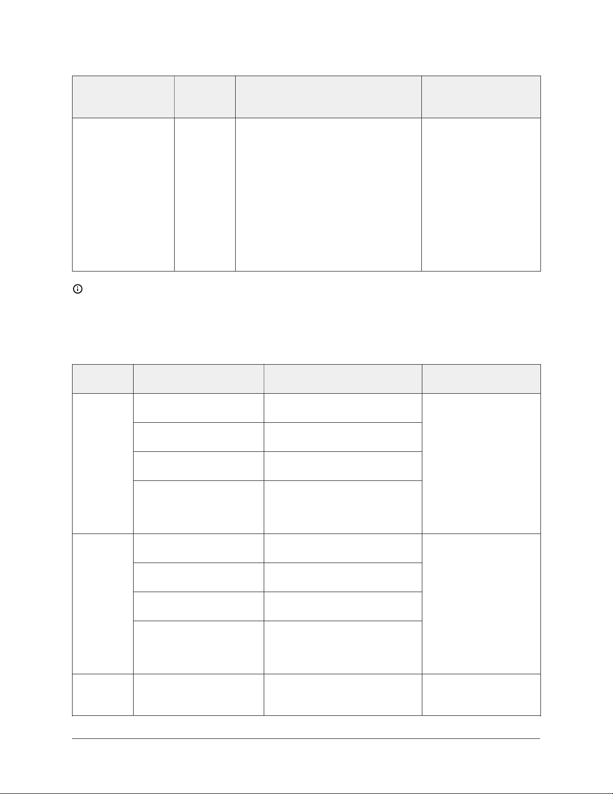
Table 2: I/O terminal blocks, functions, ratings, requirements, and cables
Terminal block
label
Terminal
labels
Function, ratings, and
requirements
To determine wire size
and maximum cable
length
OCOMn Analog Output Signal Common:
All Configurable Outputs defined as
Same as (Configurable)
OUTn.
Analog Outputs share a common,
which is isolated from all other
commons except the Binary Input
common.
Binary Output Signal Common:
All Configurable Outputs defined
as Binary Outputs are isolated from
all other commons, including other
Configurable Output commons.
Note: See Table 3 to determine wire size and cable lengths for cables other than the
recommended cables.
The following table defines cable length guidelines for the various wire sizes that may be used for
input and output wiring.
Table 3: Cable length guidelines for recommended wire sizes
Guideline Wire Size/Gauge and
Type
A
1.0 mm (18 AWG)
stranded copper
0.8 mm (20 AWG)
stranded copper
0.6 mm (22 AWG)
stranded copper
0.5 mm (24 AWG)
stranded copper
Maximum Cable Length and
Type
457 m (1,500 ft) twisted wire
297 m (975 ft) twisted wire
183 m (600 ft) twisted wire
107 m (350 ft) twisted wire
Assumptions
100 mV maximum
voltage drop
Depending on the
cable length and the
connected input or
output device, you may
have to define an offset
in the setup software
for the input or output
point.
B
1.0 mm (18 AWG)
stranded copper
0.8 mm (20 AWG)
stranded copper
0.6 mm (22 AWG)
stranded copper
0.5 mm (24 AWG)
stranded copper
229 m (750 ft) twisted wire
137 m (450 ft) twisted wire
91 m (300 ft) twisted wire
61 m (200 ft) twisted wire
100 mV maximum
voltage drop
Depending on the
cable length and the
connected input or
output device, you may
have to define an offset
in the setup software
for the input or output
point.
C See Figure 7 to select wire
size/gauge. Use stranded
See Figure 7 to determine cable
length. Use twisted wire cable.
N/A
copper wire.
11FX-PCV Programmable Variable Air Volume Box Controllers Installation Instructions
Page 12

Termination details
A set of Johnson Controls termination diagrams provides details for wiring inputs and outputs to
the controllers. See the figures in this section for the applicable termination diagrams.
Table 4: Termination details
Type of field
device
Temperature
Sensor
Voltage Input External Source
Voltage Input Internal Source
Type of
Input/
Output
UI
UI
UI
Termination diagrams
Voltage Input
(Self-Powered)
Dry Contact
(Binary Input)
FX-PCV Programmable Variable Air Volume Box Controllers Installation Instructions12
UI
UI
Page 13

Table 4: Termination details
Type of field
device
0–10 VDC Output
to Actuator
(External Source)
0–10 VDC Output
to Actuator
(Internal Source)
Analog Output
(Voltage)
Type of
Input/
Output
CO or AO
CO or AO
CO or AO
Termination diagrams
24 VAC Triac
Output (Switch
Low, External
Source)
Incremental
Control to
Actuator (Switch
Low, Externally
Sourced)
24 VAC Binary
Output (Switch
Low, Internal
Source)
CO or AO
CO or AO
BO
13FX-PCV Programmable Variable Air Volume Box Controllers Installation Instructions
Page 14

Table 4: Termination details
Type of field
device
Incremental
Control to
Actuator (Switch
Low, Internal
Source)
Network Stat with
Phone Jack (Fixed
Address = 199)
Network Stat
with Terminals
Addressable
Type of
Input/
Output
BO
SA Bus
SA Bus
Termination diagrams
.
Network Stat with
Terminals (Fixed
Address = 199)
SA Bus
Maximum cable length versus load current
Use Figure 7 to estimate the maximum cable length relative to the wire size and the load current (in
mA) when wiring inputs and outputs.
FX-PCV Programmable Variable Air Volume Box Controllers Installation Instructions14
Page 15

Maximum wire length by current and wire size figure
Figure 7: Maximum wire length by current and wire size
FC and SA bus and supply power wiring guidelines
Table 5 provides information about terminal block functions, ratings, and requirements.
Table 5 also provides wire size, cable type, and cable length guidelines for wiring the FX-PCV
communication buses and supply power.
In addition to the guidelines in Table 5, observe these guidelines when wiring the SA/FC Buses and
supply power:
• Run all low-voltage wiring and cables separate from high-voltage wiring.
• All FC and SA Bus cables, regardless of wire size, should be twisted, insulated, stranded copper
wire.
• Shielded cable is strongly recommended for all FC and SA Bus cables.
• Refer to the FX-PC Series Controllers MS/TP Communications Bus Technical Bulletin (LIT-12011670) for
detailed information regarding wire size and cable length requirements for the FC and SA buses.
15FX-PCV Programmable Variable Air Volume Box Controllers Installation Instructions
Page 16

Communication bus and supply power table
Table 5: Communication bus and supply power terminal blocks, functions, ratings,
requirements, and cables
Terminal
block/Port
label
FC BUS
SA BUS
SENSOR
2
2
2
(SA Bus Port)
Terminal labels Function, electrical ratings/
Requirements
+
FC Bus Communications
-
COM Signal Reference (Common) for bus
communications
SHLD Isolated terminal (optional shield
drain connection)
+
SA Bus Communications
-
COM SA Bus Signal Reference and 15 VDC
Common
SA PWR 15 VDC Supply Power for Devices on
the SA Bus
SENSOR RJ-12 6-Position Modular Connector
provides:
SA Bus Communications
Recommended cable
1
type 1
0.6 mm (22 AWG)
stranded, 3-wire
twisted, shielded cable
recommended
0.6 mm (22 AWG)
stranded, 4-wire (2
twisted-pairs), shielded
cable recommended
The + and - wires are
one twisted pair and the
COM and SA PWR are
the second twisted pair
of wires.
24 AWG 3-pair CAT 3
Cable
<30.5 m (100 ft)
SA Bus Signal Reference and 15 VDC
Common
15 VDC Power for devices on the SA
Bus
24~
HOT 24 VAC Power Supply - Hot
Supplies 20 to 30 VAC (Nominal 24
0.8 mm to 1.0 mm
(20 to 18 AWG) 2-wire
VAC)
COM 24 VAC Power Supply Common
(Isolated from all other Common
terminals on controller)
1 See Table 3 to determine wire size and cable lengths for cables other than the recommended cables.
2 The SA Bus and FC Bus wiring recommendations in this table are for MS/TP bus communications at 38.4k baud. For
more information, refer to the FX-PC Series Controllers MS/TP Communications Bus Technical Bulletin (LIT-12011670).
FX-PCV Programmable Variable Air Volume Box Controllers Installation Instructions16
Page 17

Setup and adjustments
Important: Electrostatic discharge can damage controller components. Use proper
electrostatic discharge precautions during installation, setup, and servicing to avoid damaging
the controller.
Setting the device address
FX-PCV controllers are master devices on BACnet MS/TP (SA or FC) buses. Before operating
controllers on a bus, you must set a valid and unique device address for each controller on the bus.
You set a controller's device address by setting the positions of the switches on the Device Address
DIP switch block at the top of the controller (Figure 2). Valid addresses for these controllers are
device addresses 4 through 127.
The DIP switch block (Figure 8) has eight switches numbered 128, 64, 32, 16, 8, 4, 2, and 1. Switches
64 through 1 are device address switches. Switch 128 is a mode switch that enables a field
controller to operate on an FX-ZFR Series Wireless Field Bus. Switch 128 must be set to off for all
hard-wired SA and FC Bus applications.
Figure 8: Device address switches set to 21
Note: FX-PCV controllers ship with switch 128 ON and the remaining address switches off. This
renders the controllers wired subordinate devices, which do not operate on MS/TP buses, but
do not interfere with bus operation. Set a valid and unique device address on the controller
before applying power to the controller on the bus.
To set the device addresses on an FX-PCV controller:
1. Set all of the switches on the controller’s device address DIP switch block (128 through 1) to off.
2. Set one or more of the seven address switches (64 through 1) to ON, so that the sum of the
switch numbers set to ON equals the intended device address. See Table 6 for valid controller
addresses. Set the highest number switch that is less than or equal to the intended device
address to ON. Then continue setting lower numbered switches until the total equals the
intended address. For example, if the intended device address is 21, set switch 16 to ON first,
then set switch 4 ON, followed by switch 1 (16+4+1= 21). See Figure 8.
Note: Do not connect a field controller with switch 128 set to ON to an active (hard-wired)
SA or FC Bus. When a controller with switch 128 set to ON and a device address from 4 to
127 is connected to a wired field bus, the entire field bus is rendered inoperable until the
controller is disconnected or switch 128 is set to OFF.
3. Set a unique and sequential device address for each of the controllers connected on the SA
or FC Bus starting with device address 4. To ensure the best bus performance, set sequential
device addresses with no gaps in the device address range (for example, 4, 5, 6, 7, 8, and 9).
The controllers do not need to be physically connected on the bus in their numerical device
address order.
4. Write each controller's device address on the white label below the DIP switch block on the
controller's cover.
17FX-PCV Programmable Variable Air Volume Box Controllers Installation Instructions
Page 18
Refer to the FX-PC Series Controllers MS/TP Communications Bus Technical Bulletin (LIT-12011670) for
more information on field controller device addresses and how to set them on MS/TP buses.
Table 6 describes the valid FC Bus and SA Bus devices addresses for Johnson Controls® MS/TP
communications bus applications.
Table 6: SA/FC bus device address descriptions
Device address Address description
0
(Switch 128 Off)
1 to 3
(Switch 128 Off)
4 to 127
(Switch 128 Off)
Reserved for FC Bus Supervisory Controller. Not valid for controllers.
Reserved for peripheral devices. Not valid for controllers.
Valid for MS/TP Master controllers on a hardwired SA Bus or FC Bus.
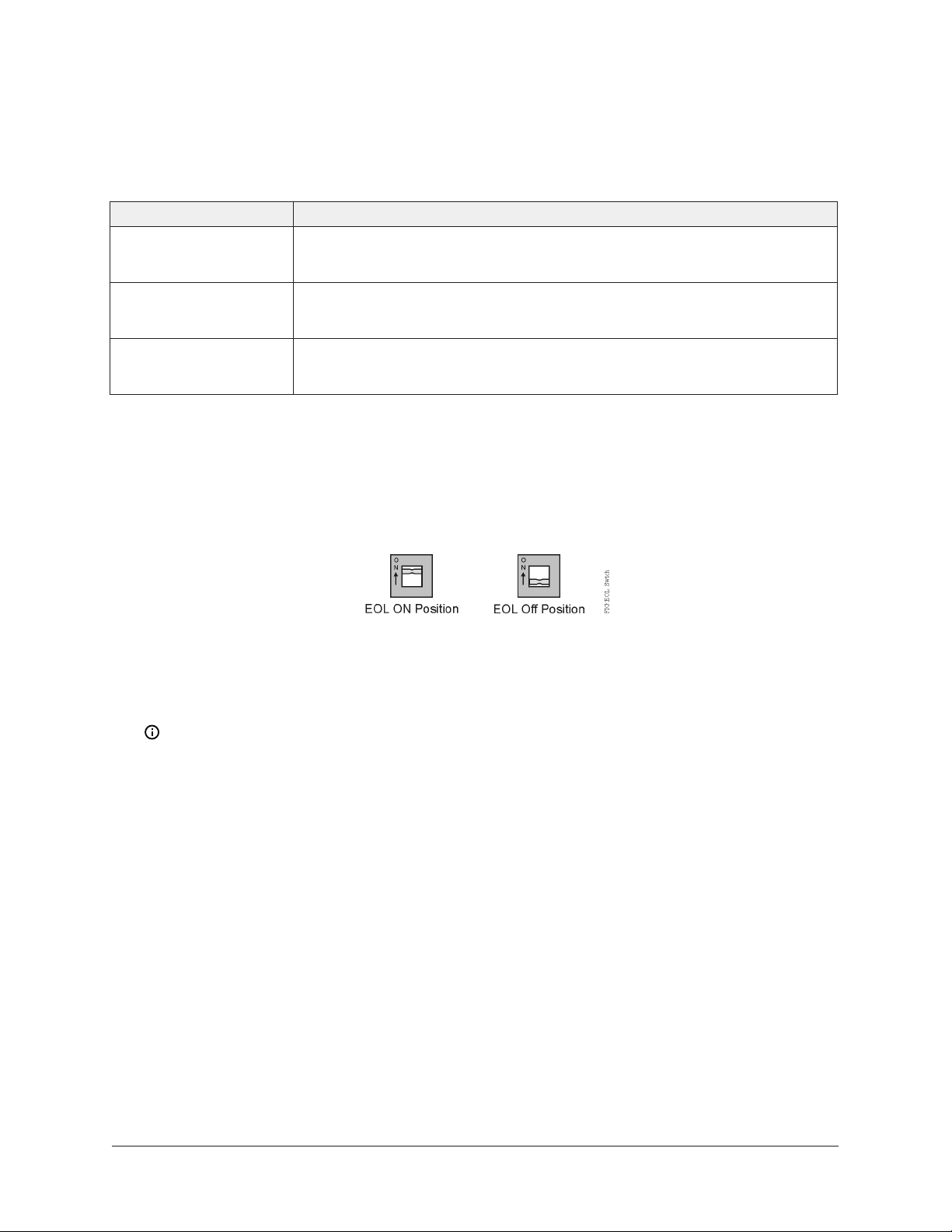
Setting the EOL switch
Each controller has an End-of-Line (EOL) switch, which, when set to ON (up), sets the FX-PCV
controller as a terminating device on the bus. See Figure 2 for the EOL switch location on the
controller. The default EOL switch position is off (down).
Figure 9: EOL switch positions
To set the EOL switch on an FX-PCV controller:
1. Determine the physical location of the FX-PCV controller on the SA or FC Bus.
2. Determine if the controller must be set as a terminating device on the bus.
Note: The EOL termination rules for SA Buses and FC Buses are different. Refer to the FX-
PC Series Controllers MS/TP Communications Bus Technical Bulletin (LIT-12011670) for detailed
information regarding EOL termination rules and EOL switch settings on SA and FC Buses.
3. If the controller is a terminating device on the SA Bus or FC Bus, set the EOL switch to ON. If
the controller is not a terminating device on the bus, set the EOL switch to off.
Commissioning
Use the following procedure to commission the FX-PCV controller:
1. Download the control application to the FX-PCV controller using the Controller Configuration
Tool (CCT). Refer to the Controller Tool Help (LIT-12011147).
2. Commission the VAV Box. Refer to the Controller Tool Help (LIT-12011147).
3. Balance the airflow on the VAV box. Refer to the VAV Balancing Tool Technical Bulletin
(LIT-12011087).
4. Perform commissioning checkout procedures. Refer to the Controller Tool Help (LIT-12011147).
FX-PCV Programmable Variable Air Volume Box Controllers Installation Instructions18
Page 19

Troubleshooting
Table 7 provides LED status indicator information to help troubleshoot the FX-PCV controller.
Table 7: FX-PCV16 Series Controller status LEDs
LED label LED color Normal state Descriptions of LED states
POWER Green On Steady Off Steady = No power
On Steady = Power is supplied by primary
voltage.
FAULT Red Off Steady Blink - 2 Hz = Download or startup in progress;
not ready for normal operation
Off Steady = No faults
On Steady = Device fault or no application
loaded
FC BUS Green Blink - 2 Hz Blink - 2 Hz = Data transmission (normal
communication)
Off Steady = No data transmission (auto baud
in progress)
On Steady = Communication lost, waiting to
join communication ring
SA BUS Green Blink - 2 Hz Blink - 2 Hz = Data transmission (normal
communication)
Off Steady = No data transmission (N/A - auto
baud not supported)
On Steady = Communication lost, waiting to
join communication ring
Repair information
If the FX-PCV controller fails to operate within its specifications, contact the Johnson Controls Repair
Center in Louisville, Kentucky, at 1-502-671-7312.
Accessories
Use Table 8 to order accessories.
Table 8: FX-PCV accessories (order separately)
Product code number Description
PAN-PWRSP-U Transformer, 96 VA Class 2 120/24 VAC power supply, compliant for UL
864 UUKL/UUKLCTenth Edition Smoke Control System
AP-TBK1002-0 2-position Screw Terminal that Plugs onto FX-PCV Output Point Spade
Lugs
AP-TBK1003-0 3-position Screw Terminal that Plugs onto FX-PCV Output Point Spade
Lugs
19FX-PCV Programmable Variable Air Volume Box Controllers Installation Instructions
Page 20

Table 8: FX-PCV accessories (order separately)
Product code number Description
AP-TBK4SA-0 Replacement MS/TP SA Bus Terminal, 4-Position Connector, Brown (Bulk
Pack of 10)
AP-TBK4FC-0 Replacement MS/TP FC Bus Terminal, 4-Position Connector, Blue (Bulk
Pack of 10)
AP-TBK3PW-0 Replacement Power Terminal, 3-Position Connector, Gray (Bulk Pack of
10)
TL-BRTRP-0 BACnet IP to MS/TP Router for Connecting a Computer with CCT to MS/
TP Field Controllers
FX-BTCVTCBL-700 Cable Replacement Set for the FX-BTCVT-1 or the FX-ATV7003-0; Includes
One 5 ft (1.5 m) Retractable Cable
NS Series Sensors NS Series Network Sensors: Refer to the NS Series Network Sensors
Product Bulletin (LIT-12011574) for specific sensor model descriptions
Technical specifications
Table 9: FX-PCV16 Controllers
Product Code
Numbers
Supply Voltage 24 VAC (nominal, 20 VAC minimum/30 VAC maximum), 50/60 Hz, power
Power Consumption 10 VA typical, 14 VA maximum
Ambient Conditions Operating: 0°C to 50°C (32°F to 122°F)
Terminations Inputs/Outputs: 6.3 mm (1/4 in.) spade lugs
FX-PCV1610-0U: 1 UI FX-PCV (Cooling Only)
FX-PCV1610-1U: 1 UI FX-PCV (Cooling Only)
FX-PCV1620-0U: 1 UI, 3 BO, 2 CO FX-PCV (Cooling with Reheat and Fan
Control)
Note: FX-PCV1620-1U: 1 UI, 3 BO, 2 CO FX-PCV (Cooling with
Reheat and Fan Control)Only -xU models of these controllers are
available. These models are for smoke control applications only.
If your application is not for a UL 864 UUKL 10th Edition smoke
control application, please review the product selection before
installation.
supply Class 2 (North America), Safety Extra-Low Voltage (SELV) (Europe)
Note: VA rating does not include any power supplied to the
peripheral devices connected to Binary Outputs (BOs) or
Configurable Outputs (COs), which can consume up to 12 VA for
each BO or CO for a possible total consumption of an additional 60
VA (maximum).
Storage: -40°C to 70°C (-40°F to 158°F)
FC Bus, SA Bus, and Supply Power: 4-Wire and 3-Wire Pluggable Screw
Terminal Blocks
Sensor Port: RJ-12 6-Pin Modular Jacks
FX-PCV Programmable Variable Air Volume Box Controllers Installation Instructions20
Page 21

Table 9: FX-PCV16 Controllers
Controller Addressing DIP switch set; valid controller device addresses 4–127
(Device addresses 0–3 and 128–255 are reserved and not valid controller
addresses.)
Communications Bus BACnet MS/TP, RS-485:
3-wire FC Bus between the supervisory controller and controllers
4-wire SA Bus between FX-PCV controller, network sensors and other
sensor/actuator devices; includes a terminal to source 15 VDC supply
power from FX-PCV to SA Bus devices 1
1
Input and Output
Capabilities
Analog Input/Analog
Output Resolution and
Accuracy
Air Pressure
Differential Sensor
FX-PCV1610:
1 - Universal Input: Defined as 0–10 VDC, 0–600k ohm, or Binary Dry
Contact
FX-PCV1620:
1 - Universal Input: Defined as 0–10 VDC, 0–600k ohm, or Binary Dry
Contact
3 - Binary Outputs: Defined as 24 VAC Triac (internal power source)
2 - Configurable Outputs: Defined as 0–10 VDC or 24 VAC Triac BO
Analog Input: 15-bit resolution
Analog Output: 16-bit resolution and ±200 mV in 0–10 VDC applications
Setra transducer, differential pressure to electrical, 0 mm to 38.1 mm (0
to 1.5 in.) WC, 0.5 VDC to 4.5 VDC, 5 VDC supply, aluminum plated
Performance Characteristics:
Combined Repeatability and Hysteresis Error: ±0.05% of Full Span
Maximum
Non-linearity Errors (Best Fit Method): ±1.0% of Full Span Maximum
Response Time (to within 63% of Full Scale Pressure with Step Change on
Input): 15 ms
Temperature Error from 15.6°C to 48.9°C (60°F to 120°F)
Null: ±0.06% of Full Span per °F Maximum
Span: ±1.5% of Full Span Maximum
Stability, Null: ±0.5% of Full Scale Maximum, 1 Year Minimum
Stability, Span: ±2.0% of Full Scale Maximum, 1 Year Minimum
Actuator Rating Torque: 4 N·m (35 lb·in)
Stroke Time: 60 sec at 60 Hz, 72 sec at 50 Hz
Minimum Shaft Length: 44 mm (1-3/4 in.)
Mounting Mounts to damper shaft using single set screw and to duct with single
mounting screw.
21FX-PCV Programmable Variable Air Volume Box Controllers Installation Instructions
Page 22

Table 9: FX-PCV16 Controllers
Dimensions
(Height x Width x
Depth)
182 mm x 182 mm x 64 mm (7-3/16 x 7-3/16 x 2-1/2 in.)
Note: Center of output hub to center of anti-rotation slot is 160mm
(6-5/16 in.).
Weight 0.86 kg (1.9 lb)
Compliance
United States: UL Listed, File E107041, CCN PAZX, UL 916, Energy
Management Equipment; FCC Compliant to CFR47, Part 15, Subpart B,
Class A
Canada: UL Listed, File E107041, CCN PAZX7, CAN/CSA C22.2 No. 205,
Signal Equipment; UL Listed, File S4977, UUKLC ULC-ORD-C100-13,
Smoke Control System Equipment (MS-VMA1610-0U, MS-VMA1610-1U,
MS-VMA1620-0U, and MS-VMA1620-1U models only); Industry Canada
Compliant, ICES-003
Europe: CE Mark – Johnson Controls declares that this product is
in compliance with the essential requirements and other relevant
provisions of the EMC Directive.
Australia and New Zealand: RCM Mark, Australia/NZ Emissions
Compliant.
BACnet International: BACnet Testing Laboratories (BTL) Protocol
Revision 7 Listed BACnet Application Specific Controller (B-ASC)
1 For more information, refer to the FX-PC Series Controllers MS/TP Communications Bus Technical Bulletin (LIT-12011670).
The performance specifications are nominal and conform to acceptable industry standard. For
application at conditions beyond these specifications, consult the local Johnson Controls office. Johnson
Controls shall not be liable for damages resulting from misapplication or misuse of its products.
Points of single contact
APAC Europe NA/SA
JOHNSON CONTROLS
C/O CONTROLS PRODUCT MANAGEMENT
NO. 32 CHANGJIJANG RD NEW DISTRICT
WUXI JIANGSU PROVINCE 214028
CHINA
JOHNSON CONTROLS
WESTENDHOF 3
45143 ESSEN
GERMANY
JOHNSON CONTROLS
507 E MICHIGAN ST
MILWAUKEE WI 53202
USA
© 2019 Johnson Controls. All rights reserved. All specifications and other information shown were current as of document
revision and are subject to change without notice.
www.johnsoncontrols.com
 Loading...