

Page 1

(barcode for factory use only)
FEU2610 Field Equipment Controller
Installation Instructions
MS-FEU2610-0U
Applications
The MS-FEU2610-0U controller is a member of the Metasys® system Field Equipment Controller (FEC) family.
The FEU26 is designed to run a variety of pre-engineered or user-programmed Heating, Vent ilating, and Air
Conditioning (HVAC) applications, and provides the inputs/outputs required for these applications.
IMPORTANT: The MS-FEU2610-0U controller is used in Metasys Release 8.1 smoke control applications and
is UL 864 UUKL/UUKLC 10th Edition Smoke Control Listed. You must refer to the Metasys® System UL 864
10th Edition UUKL/ORD-C100-13 UUKLC Smoke Control System (LIT-120 12487) for detailed requir ements and
procedures for installing, commissioning, and operating all UL 864 UUKL/UUKLC Listed Metasys system
devices. The UL 864 UUKL/UUKLC listing for Smoke Control Equipment is voided if (1) you do not use the
required software tools at the required versions; or (2) you do not meet the requirements or do not follow the
procedures as documented in the Metasys® System UL 864 10th Edition UUKL/ORD-C100-13 UUKLC Smoke
Control System (LIT-12012487).
Part No. 24-10143-543, Rev. B
Release 8.1
Issued March 2018
North American Emissions Compliance
Canada
This Class (A) digital apparatus meets all the requirements of the Canadian Interference-Causing Equipment
Regulations.
Cet appareil numérique de la Classe (A) respecte toutes les exigences du Règlement sur le matériel brouilleur
du Canada.
United States
This equipment has been tested and found to comply with the limits for a Class A digital device pursuant to
Part 15 of the FCC Rules. These limits are designed to provide reasonable protection against harmful
interference when this equipment is operated in a commercial environment. This equipment generates, uses,
and can radiate radio frequency energy and, if not inst alled an d used in accordance with the instruction manual,
may cause harmful interference to radio communications. Operation of this equipment in a residential area is
likely to cause harmful interference, in which case the user will be required to correct the interference at his/her
own expense.
FEU2610 Field Equipment Controller Installation Instructions
1
Page 2

Figure 1: FEU2610 Controller Physical Features and Wiring Terminals
O
N
A
D
D
R
E
S
S
A
D
D
R
E
S
S
Ø
=
A
L
L
O
F
F
C
O
M
+
–
S
H
L
D
O
U
T
2
O
C
O
M
2
O
U
T
1
O
C
O
M
1
O
U
T
3
O
C
O
M
3
C
O
M
+
–
1
5
V
U
N
I
V
E
R
S
A
L
E
O
L
S
t
a
t
u
s
L
E
D
s
D
e
v
i
c
e
A
d
d
r
e
s
s
D
I
P
S
w
i
t
c
h
B
l
o
c
k
B
i
n
a
r
y
O
u
t
p
u
t
s
T
y
p
i
c
a
l
l
y
2
4
V
A
C
T
r
i
a
c
o
u
t
p
u
t
s
V
o
l
t
a
g
e
A
n
a
l
o
g
O
u
t
p
u
t
B
i
n
a
r
y
O
u
t
p
u
t
(
0
-
1
0
V
D
C
)
(
2
4
V
A
C
T
r
i
a
c
)
V
C
U
n
i
v
e
r
s
a
l
I
n
p
u
t
s
V
o
l
t
a
g
e
A
n
a
l
o
g
I
n
p
u
t
C
u
r
r
e
n
t
A
n
a
l
o
g
I
n
p
u
t
R
e
s
i
s
t
i
v
e
A
n
a
l
o
g
I
n
p
u
t
s
:
D
r
y
C
o
n
t
a
c
t
B
i
n
a
r
y
I
n
p
u
t
c
a
n
b
e
d
e
f
i
n
e
d
a
s
:
(
0
-
1
0
V
D
C
)
(
4
-
2
0
m
A
)
0
-
2
k
o
h
m
R
T
D
:
1
k
N
i
c
k
e
l
,
1
k
P
l
a
t
i
n
u
m
,
o
r
A
9
9
B
S
I
N
T
C
:
1
0
k
T
y
p
e
L
o
r
2
.
2
5
2
k
T
y
p
e
2
B
i
n
a
r
y
I
n
p
u
t
s
D
r
y
C
o
n
t
a
c
t
M
a
i
n
t
a
i
n
e
d
P
u
l
s
e
C
o
u
n
t
e
r
M
o
d
e
c
a
n
b
e
d
e
f
i
n
e
d
a
s
:
(
1
0
0
H
z
h
i
g
h
-
s
p
e
e
d
)
N
O
T
E
:
F
I
G
:
F
E
C
2
6
2
0
_
t
e
r
m
S
A
B
U
S
F
A
U
L
T
P
O
W
E
R
T
h
e
C
u
r
r
e
n
t
(
4
-
2
0
m
A
)
A
n
a
l
o
g
I
n
p
u
t
L
o
a
d
R
e
s
i
s
t
o
r
j
u
m
p
e
r
s
f
o
r
U
n
i
v
e
r
s
a
l
I
n
p
u
t
s
a
r
e
l
o
c
a
t
e
d
o
n
t
h
e
i
n
s
i
d
e
o
f
t
h
e
F
E
C
c
o
v
e
r
.
T
h
e
B
i
n
a
r
y
O
u
t
p
u
t
’
s
I
N
T
/
E
X
T
p
o
w
e
r
)
k
c
2
k
r
c
s
e
o
s
w
l
a
l
o
B
P
l
C
,
a
y
l
n
C
i
p
A
p
m
V
r
u
e
4
S
T
:
s
a
d
e
n
i
f
e
d
e
b
n
a
c
s
t
u
p
t
u
O
g
o
l
a
n
A
:
s
a
d
e
n
i
f
e
d
e
b
n
a
c
s
t
u
p
t
u
O
e
l
b
a
r
u
g
i
f
n
o
C
2
T
O
)
)
C
A
D
m
V
0
0
2
1
-
-
4
0
(
(
t
t
u
u
p
p
t
t
u
u
O
O
g
g
o
o
l
l
a
a
n
n
A
A
t
e
n
g
e
a
r
t
r
l
u
o
H
M
O
C
9
M
O
C
O
9
T
U
O
8
M
O
C
O
8
T
U
O
7
M
O
C
O
7
T
U
O
6
M
O
C
O
6
T
U
O
5
M
O
C
O
5
T
U
O
C
O
M
4
O
4
T
U
O
FEU2610 Field Equipment Controller Installation Instructions
w
e
r
c
S
r
e
v
o
C
a
J
r
a
t
l
r
u
o
d
P
o
s
M
u
n
B
i
P
C
-
F
6
2
1
J
R
(
O
2
e
h
n
c
i
t
i
L
-
w
f
S
o
n
d
o
n
i
t
E
a
s
n
i
u
B
m
r
e
C
T
F
N
S
U
B
A
S
R
O
S
N
E
S
8
M
O
I
C
8
I
N
Y
R
A
7
M
O
I
C
N
I
B
7
I
N
6
M
O
I
C
6
I
N
5
M
O
I
C
5
I
N
1
+
5
V
4
M
O
I
C
4
I
N
3
M
O
I
C
3
I
N
+
1
5
V
2
M
O
I
C
2
I
N
1
M
O
I
C
1
I
N
1
5
V
+
d
n
a
k
s
c
l
o
a
d
l
n
n
i
B
a
l
m
r
e
T
s
u
B
C
F
k
a
s
c
l
n
o
a
i
l
n
i
m
B
r
l
m
e
a
r
T
n
e
i
T
m
s
r
u
e
T
B
A
S
)
k
c
a
J
r
a
t
l
r
u
o
d
P
o
r
M
o
s
n
i
n
e
P
-
S
6
2
1
J
R
(
.
d
r
a
o
b
n
o
i
t
a
n
i
m
r
e
t
e
h
t
n
o
r
e
v
o
c
C
E
F
e
h
t
r
e
d
n
u
d
e
t
a
c
o
l
e
r
a
s
r
e
p
m
u
j
e
c
r
u
o
s
I
Page 3

nstallation
Observe these guidelines when installing the FEU26:
• Transport the FEU in the original container to minimize vibration and shock damage to the FEU.
• Verify that all parts shipped with the FEU.
• Do not drop the FEU or subject it to physical shock.
Parts Included
• one FEU26 with removable Terminal Plugs
• one installation instructions sheet
Materials and Special Tools Needed
• three fasteners appropriate for the mounting surface (M4 screws or #8 screws)
• one 20.3 cm (8 in.) (or longer) piece of DIN rail and appropriate hardware for mounting the DIN rail (optional)
• small straight blade screwdriver for securing communication wires in the terminal blocks
Mounting
The mounting base may be mounted without the controller cover. If you mount the mounting base without the
controller cover, ensure that there is sufficient clearance to allow later mounting of the controller cover.
Location Considerations
Follow these guidelines when mounting an FEU26:
• Ensure the mounting surface can support the FEU and any user-supplied enclosure.
• Mount the FEU in the proper orientation. See
• Mount the FEU on an even surface whenever possible.
• Use shims or washers to mount the unit securely on the mounting surface.
• Mount the FEU in areas free of corrosive vapors and observe the environmental limitations listed in the
Technical Specifications section.
• Do not mount the FEU on surfaces prone to vibration, such as duct work, or in areas where electromagnetic
emissions from other devices or wiring can interfere with FEU communication.
• Allow sufficient space for cable and wire connections (mini mum of 50 mm [2 in.] in each direction).
On panel or enclosure mount applications, observe the following guidelines:
• Do not install the FEU in an airtight enclosure.
• Mount the FEU so that the enclosure wall or the transformer does not obstruct ventilation of or radiate h eat into
the FEU housing.
.
Figure 3 and Figure 4.
FEU2610 Field Equipment Controller Installation Instructions
3
Page 4

Wall Mount Applications
Figure 2: DIN Rail and Mounting Clip Features on the Back of an FEU26, mm (in.)
1-7/8()
90
3-1/2()
90
3-1/2()
143
5-5/8()
127
5()
DIN Rail
Channel
DIN Rail
Hooks
95
3-3/4()
FIG:FEC2620mnt dim
Mounting C lips
48
1-7/8()
48
()
Figure 3: Required Orientation for Wall Mount Applications
To mount the FEU26 on a wall (or other vertical surface):
1. Ensure that all three mounting clips are pulled outward an d snapped firmly into the extended position. See
Figure 2.
48
1-7/8
(in Ext e nded Po s i ti ons)
2. Mark the location of the mounting holes on the wall using the dimensions in
orientation in
Figure 3. (Or hold the FEU up to the wall as a template and mark the hole locations.)
3. Drill holes in the wall at the locations marked in Step 2, and insert appropriate wa ll anchor s in all three holes (if
necessary).
4. Hold the FEU26 in place, and insert the screws through the mounting clips and into the holes. Carefully tighten
all of the screws.
IMPORTANT: Do not over tighten the mounting screws. Ove r tightening the scre ws may damage the mounting
clips.
Figure 2 and according to the
FEU2610 Field Equipment Controller Installation Instructions
4
Page 5

DIN Rail Mount Applications
Figure 4: Required Orientation for DIN Rail Mount Applications
Figure 5: Attaching the Cover to the Mounting Base
To mount the FEU26 on a DIN rail:
1. Securely mount a 20.3 cm (8 in.) (or longer) section o f DIN ra il ho rizontally and centered in the required sp ace.
2. Ensure that the bottom two mounting clips are pulled outward and snapped firmly into the extended position.
See
Figure 2.
3. Hang the FEU26 by the DIN rail hooks (
Figure 2) on the top track of the DIN rail, and position the FEU26 DIN
rail channel snugly against the tracks of the DIN rail.
4. Push the bottom mounting clips up to secure the FEU26 on the DIN rail tra cks .
To remove the FEU26 from the DIN rail, snap the bottom DIN clips to the extended position, and carefully lift the
FEU26 off the DIN rail.
Attaching the Cover
You may attach the cover before or after wiring the FEU26.
1. Place the hinge tabs (cover) onto the top of the hinge slots (the mounti ng base). See
Note: Do not fully insert the tabs into the slots. If the tabs are fully inserted into the slots, the cover may not close.
2. Close the cover and tighten the cover screw to secure the cover to the base.
Figure 5.
FEU2610 Field Equipment Controller Installation Instructions
5
Page 6

Wiring
Figure 6: SA Bus Terminal Block Wiring
Observe the following guideline when wiring a controller:
Electric Shock:Disconnect the power supply before making electrical connections to avoid electric shock.
Mise En Garde: Risque de décharge électrique: Débrancher l'alimentation avant de réaliser tout raccordement
électrique afin d'éviter tout risque de décharge électrique.
For information on the MS/TP Bus, refer to the MS/TP Communications Bus Technical Bulletin (LIT-12011034).
To install the FEU26, see
Hard-Wired Installation.
Hard-Wired Installation
To install an FEU26 for hard-wired operation, perform the steps that follow. See Figure 1 for jack and terminal block
locations.
Input/Output Terminals
Terminate Input/Output (I/O) point wiring at the controller per engineering drawings. See
information.
SA Bus Terminal Block and Sensor Port
Wire Network Sensors and other devices to the Sensor Actuator (SA) Bus terminal block (
(RJ-12 modular jack) for sensors.
Table 2 for more I/O wiring
Figure 6) or Sensor port
Note: The FEU26 should be at one end of the SA Bus daisy chain. If multiple Input/Output Modules (IOMs) are
used, set the End-of-Line (EOL) switch on the last IOM.
FC Bus Terminal Block
Wire the Field Controller (FC) Bus in a daisy chain to other devices on the FC Bus and the supervisory controller.
See
Figure 7 to terminate the wires.
Note: The Shield terminal (SHLD) on the FC Bus terminal block is isolated and can be used as a convenient
terminal for connecting the bus cable shield (if shielded cable is used on the bus).
FEU2610 Field Equipment Controller Installation Instructions
6
Page 7

FC Bus Port
Figure 7: FC Bus Terminal Block Wiring
Figure 8: 24 VAC Supply Power Terminal Block Wiring
FEC
Supply Power
Te rminal Block
Plug
Wires from
Johnson Controls
24 VAC, Class 2
Power Transformer
(COM)
(24 VAC)
FIG:FEC_Pwer_Prt
24V~
COM
HOT
The FC Bus port on the front of the FEU is an RJ-12, 6-position modular jack. The FC Bus port is not used in the
MS-FEx26x0-0U Field Equipment Controller.
Sensor Port
The Sensor (SA Bus) port on the bottom of the FEU (
Figure 1) is an RJ-12, 6-position modular jack that provides a
connection for the VAV Balancing Tool, specified network sensors, or other SA Bus devices with RJ-12 plugs.
The Sensor port is connected internally to the SA Bus terminal block. See
Port pin assignment is shown in
Device Address DIP Switches
Ensure the device address DIP switches are set to the appropriate address (in the range of 4-127). Be sure that
DIP switch 128 is set to Off. For more details on setting the DIP switches, see
Power Wiring
To wire the FEU26 for power, connect the 24 VAC supply power wires from the transformer to the removable 3terminal plug as shown in
Note: Connect 24 VAC power to all network devices so transformer phasing is uniform across the devices.
Powering devices with uniform 24 VAC supply power phasing reduces noise, interference, and ground loop
problems. The FEU does not require an eart h gr ou n d co nn ection.
Figure 8.
Figure 8. The middle terminal is not used.
Supply Power
Terminal Block
Brown Wire
Orange Wire
Table 2 for more information. The Sensor
Setting the FC Bus Address.
FEC
FEU2610 Field Equipment Controller Installation Instructions
7
Page 8

Wire Gauges and Lengths
See Table 1 for the field controller platform wiring list and Table 3 for alternative wire gauges and lengths.
Table 1: Field Controller Platform Wiring List (Part 1 of 3)
Terminal
Block
Universal IN +15 V Provides 15 VDC power for active devices connected to
Binary IN IN n Binary Input, Dry Contact Maintained Mode
Terminal
Function and Electrical Ratings/Requirements Recommended Cable Type
Labels
the Universal IN terminal blocks (3-wire connections).
100 mA total current
IN n Analog Input, Voltage Mode
Accepts a 0-10 VDC input signal.
10 VDC Maximum Input Voltage
Internal 75k ohm Pulldown
Analog Input, Current Mode
Accepts a 4-20 mA input signal.
Internal 100 ohm load Impedence enabled/disabled by
jumper
Analog Input, Resistive Mode
Accepts 0-600k ohm input signal
Internal 12 V, 15k ohm Pullup
RTD (1k Nickel [Johnson Controls], 1k Platinum, A99B
Silicon Temperature Sensor)
Negative Temperature Coefficient (NTC) Sensor
(10k Type L, 2.252k Type 2)
Binary Input, Dry Contact Maintained Mode
1 second minimum pulse width (0.5 Hz at 50% duty cycle)
Internal 12 V, 15k ohm Pullup
ICOM n The signal common for all Universal IN terminals;
isolated from all other terminal commons.
0.01 second min. pulse width (50 Hz at 50% duty cycle)
Internal 8 V, 3k ohm Pullup
Binary Input, Pulse Counter Mode
0.01 second min. pulse width (50 Hz at 50% duty cycle)
Internal 8 V, 3k ohm Pullup
ICOM n The signal common for all Binary IN terminals; isolated
from all other terminal commons, excluding CO terminal
commons that are configured as Analog Outputs (AOs).
and Length
0.6 mm (22 AWG) stranded, 3-wire
twisted, non-shielded cable for
runs of <30 m (90 ft)
Same as IN. See IN n cable type.
0.6 mm (22 AWG) stranded, 2-wire
twisted, non-shielded cable for
runs of <30 m (90 ft)
(Row A in Table 2)
0.6 mm (22 AWG) stranded, 2-wire
twisted, non-shielded cable
(Row B in Table 2)
0.6 mm (22 AWG) stranded, 2-wire
twisted, non-shielded cable for
runs of <30 m (90 ft)
(Row A in Table 2)
0.6 mm (22 AWG) stranded, 2-wire
twisted, non-shielded cable for
runs of <30 m (90 ft)
(Row A in Table 2.)
0.6 mm (22 AWG) stranded, 2-wire
twisted, non-shielded cable for
runs of <30 m (90 ft)
Same as IN. See IN n cable type.
Note: Use 3-wire cable for active
devices that connect to the +15 V
terminal also.
0.6 mm (22 AWG) stranded, 2-wire
twisted, non-shielded cable for
runs of <30 m (90 ft)
(Row A in Table 2)
1
FEU2610 Field Equipment Controller Installation Instructions
8
Page 9

Table 1: Field Controller Platform Wiring List (Part 2 of 3)
Terminal
Block
Analog OUT OUT n Analog Output, Voltage Mode
Binary OUT
(Jumper Set
to External)
Binary OUT
(Jumper Set
to Internal)
Configurable
OUT
2,3
Sensor
Terminal
Function and Electrical Ratings/Requirements Recommended Cable Type
Labels
Sources 0-10 VDC output voltage
External 1k ohm minimum load required
10 VDC maximum output voltage
10 mA maximum output current
Analog Output, Current Mode
Sources 4-20 mA output current
External 300 ohm maximum load required
OCOM n The signal common for all Analog OUT terminals; isolated
OUT n Binary Output, 24 VAC Triac
OCOM n The signal common for Binary OUT terminals; isolated
OUT n Sources 24~ Power (Hot) 0.6 mm (22 AWG) stranded, 2-wire
OCOM n Binary Output, 24 VAC Triac
OUT n Analog Output, Voltage Mode
OCOM n Analog Output: The signal common for all analog
Sensor Provides SA Bus communication network.
from all other terminal commons.
Connects OUT to OCOM when activated
30 VAC maximum output voltage
0.5 A maximum output current
1.3 A at 25% duty cycle
Maximum 6 cycles per hour with M9220-BGx-3
40 mA minimum load current
from all other terminal commons, including Binary Output
(BO) terminal commons.
Connects OCOM to 24~ Power (Com) when activated.
30 VAC maximum output voltage
0.5 A maximum output current
40 mA minimum load current
Sources 0-10 VDC
External 1k ohm minimum load required
10 VDC maximum output voltage
10 mA maximum output current
Binary Output 24 VAC Triac mode
Connects OUT to OCOM when activated.
30 VAC maximum output voltage
0.5 A maximum output current
1.3 A at 25% duty cycle
Maximum 6 cycles per hour with M9220-BGx-3
40 mA minimum load current
Configurable Output (CO) terminals; isolated from all
other terminal commons, excluding BI terminal commons
Binary Output: The signal common for binary-configured
CO terminals; isolated from all other terminal commons,
including other CO terminal common s
RJ-12 6-position modular connector
and Length
0.6 mm (22 AWG) stranded, 2-wire
twisted, non-shielded cable for
runs of <30 m (90 ft)
(Row A in Table 2)
0.6 mm (22 AWG) stranded, 2-wire
twisted, non-shielded cable
(Row B in Table 2)
0.6 mm (22 AWG) stranded, 2-wire
twisted, non-shielded cable for
runs of <30 m (90 ft)
(Same as OUT. See OUT cable
type.)
0.6 mm (22 AWG) stranded, 2-wire
twisted, non-shielded cable for
runs of <30 m (90 ft)
(Row C in Table 2)
twisted, non-shielded cable for
runs of <30 m (90 ft)
(Row C in Table 2)
0.6 mm (22 AWG) stranded, 2-wire
twisted, non-shielded cable for
runs of <30 m (90 ft)
(Row A in Table 2)
0.6 mm (22 AWG) stranded, 2-wire
twisted, non-shielded cable for
runs of <30 m (90 ft)
(Row C in Table 2)
0.6 mm (22 AWG) stranded, 2-wire
twisted, non-shielded cable for
runs of <30 m (90 ft)
(Same as OUT. See OUT cable
type.)
24 AWG 3-pair CAT 3 Cable
<30.5 m (100 ft)
1
FEU2610 Field Equipment Controller Installation Instructions
9
Page 10
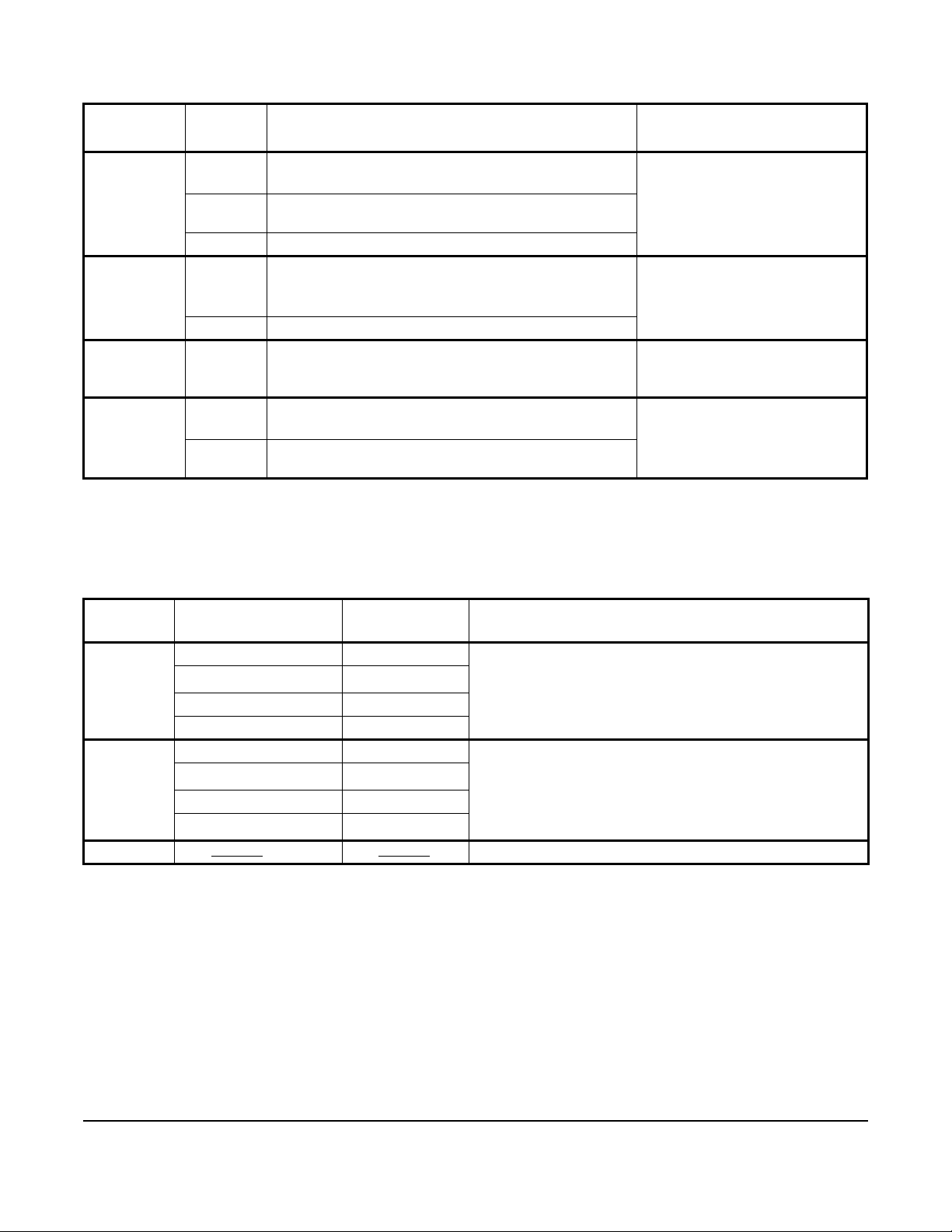
Table 1: Field Controller Platform Wiring List (Part 3 of 3)
Terminal
Block
SA Bus
FC Bus
Terminal
Block
FC Bus Port FC Bus Not used with MS-FEU2610-0U.
24~ Power Hot AC Supply Input
1. See Table 2 for alternative wire gauges and lengths.
2. The SA Bus terminals and the RJ-style modular Sensor Port are connected internally.
3. The SA Bus and FC Bus specifications in this table are for MS/TP bus communications at 38.4k baud. For more
2,3
3
information, refer to the MS/TP Communications Bus Technical Bulletin (LIT-12011034).
Terminal
Function and Electrical Ratings/Requirements Recommended Cable Type
Labels
+
COM Provides reference for network communication bus and
SA PWR Sources 15 VDC power for devices on the SA Bus
+
COM
SHLD Provides an optional shield connection.
COM The 24~ Power common; isolated from all other terminal
Provides SA Bus communication network. 0.6 mm (22 AWG) stranded, 4-wire
15 VDC source power.
Provides FC Bus communication network. 0.6 mm (22 AWG) stranded, 3-wire
RJ-12 6-position modular connector
Supply 20-30 VAC (Nominal 24 VAC)
commons.
and Length
twisted, shielded cable
recommended
twisted, shielded cable
recommended
BTCVT retractable cable or
24 AWG 3-pair CAT 3 Cable
<30.5 m (100 ft)
0.8 mm to 1.0 mm
(20 to 18 AWG) 2-wire
1
Table 2: Wire Gauge and Length Guidelines
Guideline Cable Size Maximum
Assumptions
Length
A 1.0 mm (18 AWG) 457.2 m (1,500 ft) 100 mV maximum voltage drop
0.8 mm
0.6 mm (22 AWG) 182.9 m (600 ft)
0.5 mm (24 AWG) 106.7 m (350 ft)
B 1.0 mm (18 AWG) 228.6 m (750 ft) 100 mV maximum voltage drop
0.8 mm
0.6 mm (22 AWG) 91.4 m (300 ft)
0.5 mm
C See Figure 9
(20 AWG)
(20 AWG)
(24 AWG)
.See Figure 9.N/A
297.2 m (975 ft)
137.1 m (450 ft)
61 m (200 ft)
FEU2610 Field Equipment Controller Installation Instructions
10
Page 11

Wiring Requirements
Figure 9: Maximum Wire Length by Current and Wire Size
Use
Figure 9 to determine the maximum wire length allowable when alternative wire gauges are required.
Setup and Adjustments
Determining the FC Bus Address
The FC Bus address switch sets a unique address for this controller on the FC Bus. You must set the FEU’s device
address for your field bus application.
Set consecutive device addresses 4 through 127 for Field Equipment Controllers and other master devices on the
FC Bus. Use sequential addressing with no gaps in the device address range to ensure best FC Bus performance.
Note: Switch 128 on the device address DIP switch block is not used, and should be set to Off.
Table 3 shows and describes the valid FC Bus and SA Bus devices addresses for FEUs and IOMs on Johnson
Controls® MS/TP communications bus applications.
Table 3: FC Bus Device Address Descriptions
Device
Description
Address
0 Reserved for FC Bus supervisory controller.
1-3 Reserved for peripheral devices.
4-127 Available for FEUs on the FC bus and IOMs
128 Unused.
129-255 Are not valid addresses for FEU or IOM
on the SA or FC Bus.
controllers on the SA or FC Bus.
FEU2610 Field Equipment Controller Installation Instructions
11
Page 12

Setting the FC Bus Address
Figure 10: Device Address Switches Set to 21
ON
Note:
Switch 12 8 is
not used and should
be set to .
Off
Figure 11: EOL Switch Positions
FIG:E
O
N
Figure 12: Binary Output Jumper Positions
Jumper
on top two pins
INT
EXT (Default)
FIG:Bin_Jmpr
Set the address of the FEU26 using the DIP switches on the face of the FEU26. The addr ess equals the sum of the
numbers set to ON. For example, if the first (1), the third (4), and the fifth (16) DIP switches are set to ON, the
device address is 21 (1 + 4 + 16 = 21). See
Figure 10.
128
64
32
16
8
1
4
2
FIG:fec_dip_swtch
FC Bus End-of-Line Switch
The FC Bus End-of-Line termination switch allows you to designate the FE U26 as the end of the FC Bus. The
default position is OFF. If the FEU26 is at the end of a daisy chain of devices on the FC Bus, set the EOL switch to
the ON position. See
Figure 11.
O
N
EOL ON Position EOL Off Position
OL_Swtch
Setting the Jumpers
Binary Output INT/EXT Jumpers
The Binary Output jumpers (OUT1 through OUT3) are located on the circuit board in the mounting base near the
binary outputs. These jumpers select whether the ou tp ut provides internal power to the load (INT) or requires
external power (EXT). See
IMPORT ANT: Do not set the Binary Output jumpers to INT when an external transformer is wired to the Binary
Output terminals. Failure to follow this precaution may cause damage to the cont ro ller.
Figure 12.
Table 4 describes the jumper label on the circuit board.
Table 4: Jumper Labels and UI Inputs (Part 1 of 2)
Jumper Position Universal Input (UI)
J10 UI1
J11 UI2
J12 UI3
J13 UI4
FEU2610 Field Equipment Controller Installation Instructions
Jumper positioned
Jumper positioned
Pins
on bottom two pins
12
Page 13

Table 4: Jumper Labels and UI Inputs (Part 2 of 2)
Figure 13: Analog Input Resistor Jumper Positions
Jumper
Pins
Jumper positioned
on top two pins
ENABLE
FIG:Ana_Jmpr
Jumper Position Universal Input (UI)
J14 UI5
J15 UI6
When set to the INT position, the FEU26 is the power source for the Binary Output and both sides of the load can
be wired directly to the OUTx and COMx terminals.
Setting the jumper to the EXT position isolates the Binary Outputs, and power must come from one or more
external sources. Do not wire the load directly to the OUTx and COMx terminals. Wire one side of the load to the
source and the other side of the load to the OUTx terminal. Wire the other side of the external power source to the
COMx terminal.
Analog Input Load Resistor Enable/Disable
The Analog Input Resistor Enable/Disable jumpers (J10 through J15) are located on the circuit board in the
controller cover. These jumpers can permanently connect the internal 4-20 mA, 100 ohm load resistor to the input
terminals. There is one jumper for each of the Universal Inputs. See
Figure 13.
DISABLE (Default)
Jumper positioned
on bottom two pins
Software configuration of the Universal Input normally selects the enabling or disabling of the analog input load
resistor. In cases when the analog input load resistor must be left connected even when power is OFF to the
controller, set this jumper to the ENABLE position.
Note: This jumper must be in the DISABLE position for all Universal Input modes other than 4-20 mA.
Commissioning
Commission the FEU26 with the Controller Configuration Tool (CCT). Refer to Controller Tool Help (LIT -12011147)
for details.
Troubleshooting
Use Table 5 to troubleshoot the FEU26.
Table 5: Status LEDs (Part 1 of 2)
Name Color Normal Descriptions
Power/PWR Green On Steady Off Steady = No Power
On Steady = Power is supplied by Primary Voltage.
Fault/FLT Red Off Steady Blink - 2 Hz = Download or Startup in progress, not ready for normal operation
Off Steady = No Faults
On Steady = Device Fault; no application loaded; Main Code download
required, or if controller is in Boot mode.
FEU2610 Field Equipment Controller Installation Instructions
13
Page 14

Table 5: Status LEDs (Part 2 of 2)
Name Color Normal Descriptions
SA Bus/SAB Green Blink - 2 Hz Blink - 2 Hz = Data Transmission (normal communication)
Off Steady = No Data Transmission (N/A - auto baud not supported)
On Steady = Communication lost, waiting to join communication ring
FC Bus/FCB Green Blink - 2 Hz Blink - 2 Hz = Data Transmission (normal communication)
Off Steady = No Data Transmission (auto baud in progress)
On Steady = Communication lost, waiting to join communication ring
Repair Information
The MS-FEU2610-0U model is UL 864 10th Edition UUKL/ORD-C100-13 UUKLC listed for smoke contro l. If the
device fails to operate within its specifications, contact the Johnson Controls Repair Center in Louisville, Kentucky,
at 1-502-671-7312.
Accessories
Use Table 6 to order accessories.
Table 6: FEU Accessories Ordering Information
Product Code Number Description
PAN-PWRSP-U Transformer , 120/24 VAC, 96 VA, with circuit breaker and 120 VAC outlet, approved for Smoke
Control
Technical Specifications
FEU26x0 Controller (Part 1 of 2)
Product Code Numbers MS-FEU2610-0U Field Equipment Controller Unit
Supply Voltage 20-30 VAC at 50 or 60 Hz, Class 2
Power Consumption 10 VA typical, 14 VA maximum, plus all BO and CO loads
Ambient Conditions Operating: 0 to 50°C (32 to 122°F); 10 to 90% RH noncondensing
Storage: -40 to 70°C (-40 to 158°F); 10 to 90% RH noncondensing
Terminations Screw Terminals and Screw Terminal Pluggable Blocks
Controller Addressing DIP switch set (4-127). Addresses 0-3, 128-255 are reserved.
Communications Bus BACnet® MS/TP; 3-wire FC Bus between the NAE and other devices. 4-wire SA Bus
between network sensors and other devices.
Mounting On flat surface with screws on three mounting clips or a single 35 mm DIN rail
Housing Plastic housing
Plastic material: ABS and polycarbonate UL94 5VB
Analog Input/Analog Output
Resolution and Accuracy
Dimensions
(Height x Width x Depth)
Weight 0.68 kg (1.5 lb)
Analog Input Points: 16-bit resolution
Analog Output Points: 16-bit resolution, +
180 x 127 x 58 mm (7.06 x 5 x 2.25 in.)
Minimum space for mounting: 210 x 350 x 110 mm (8.3 x 13.8 x 4.3 in.)
1
200 mV accuracy
FEU2610 Field Equipment Controller Installation Instructions
14
Page 15

Metasys® and Johnson Controls® are registered trademarks of Johnson Controls.
All other marks herein are the marks of their respective owners. © 2018 Johnson Controls.
Building Te chnologies & Solutions
507 E. Michigan Street, Milwaukee, WI 53202
FEU26x0 Controller (Part 2 of 2)
Compliance United States: UL Listed, File E107041, CCN PAZX, UL 916, Energy Management
Equipment
UL Listed, File S4977, UL 864 UUKL/UUKLC 10th Edition Listed, Smoke Control Units and
Accessories for Fire Alarm Systems Equipment
FCC Compliant to CFR47, Part 15, Subpart B, Class A
Canada: UL Listed, File E107041, CCN PAZX7, CAN/CSA C22.2 No. 205, Signal
Equipment; Industry Canada Compliant, ICES-003
UL Listed, File S4977, UL 864 UUKL/ORD-C100-13 10th Edition Listed, Smoke Control
Units and Accessories for Fire Alarm Systems
Europe: CE Mark, EMC Directive in accordance with EN 61000-6-3 and EN 61000-6-2, and
the Low Voltage Directive accordance with EN 60730-1.
Australia and New Zealand: RCM Mark, Australia/NZ Emissions Compliant
BACnet International: BACnet Testing Laboratories™ (BTL) 135-2004 Listed BACnet
Application Specific Controller (B-ASC)
1. For more information, refer to the MS/TP Communications Bus Technical Bulletin (LIT-12011034).
The performance specifications are nominal and conform to acceptable industry standard. For application at conditions beyond these
specifications, consult the local Johnson Controls® office. Johnson Controls shall not be liable for damages resulting from misapplication or
misuse of its products.
European Single Point of Contact: NA/SA Single Point of Contact: APAC Single Point of Contact:
JOHNSON CONTROLS
WESTENDHOF 3
45143 ESSEN
GERMANY
JOHNSON CONTROLS
507 E MICHIGAN ST
MIL WAUKEE WI 53202
USA
JOHNSON CONTROLS
C/O CONTROLS PRODUCT MANAGEMENT
NO. 22 BLOCK D NEW DISTRICT
WUXI JIANGSU PROVINCE 214142
CHINA
FEU2610 Field Equipment Controller Installation Instructions
Published in U.S.A. www.johnsoncontrols.com
15
 Loading...