

Johnson Controls Facility Explorer FX20, Facility Explorer FX60 Installation Instructions Manual
Page 1
Installation Instructions
Issue Date April 9, 2014
FX20/FX60 Supervisory Controllers
Installation Instructions
Application
The FX20 and FX60 are Web-based supervisory class
controllers in the Facility Explorer product family. The
FX20/FX60 manages networks of field controllers
using open communication protocols, such as N2,
L
ONWORKS®, and BACnet® protocols.
Figure 1: FX60 Supervisory Controller
North American Emissions Compliance
United States
This equipment has been tested and found to comply
with the limits for a Class A digital device pursuant to
Part 15 of the FCC Rules. These limits are designed to
provide reasonable protection against harmful
interference when this equipment is operated in a
commercial environment. This equipment generates,
uses, and can radiate radio frequency energy and, if
not installed and used in accordance with the
instruction manual, may cause harmful interference to
radio communications. Operation of this equipment in
a residential area is likely to cause harmful
interference, in which case the user will be required to
correct the interference at his/her own expense.
Canada
This Class (A) digital apparatus meets all the
requirements of the Canadian Interference-Causing
Equipment Regulations.
Installation
Parts Included
Unpack the FX20/FX60 and accessories
(power module, option cards), if ordered. Inspect the
contents of the packages for damaged or missing
components. If damaged, notify the appropriate carrier
and return any damaged components for repair or
replacement.
Included in this package are the following items:
FX Supervisory Series controller
Hardware bag contai ning a grounding wire with
quick disconnect 0.187 in. (4.75 mm) female
connector.
Power modul e (if ordered). The power module
may be one of the following:
LP-FXPM24-0
(24 VAC, DIN rail mountable)
LP-FXPM263-0
(90-263 VAC, DIN rail mountable)
LP-FXPMUS-0
(90-240 VAC, with U.S. wall adapter)
LP-FXPMEU-0
(90-240 VAC, with European wall adapter)
LP-FXPMUK-0
(90-240 VAC, with U.K. wall adapter)
Communication cards (if ordered)
LP-FXLONFTT-1
LP-FXRS232-0
LP-FXRS485-0
LP-FXMDM-0
LP-FXWTC-0
Expansion Input/Output (NDIO) Modules
(if ordered)
Cet appareil numérique de la Classe (A) respecte
toutes les exigences du Règlement sur le matériel
brouilleur du Canada.
LP-FXNDIO16-0
LP-FXNDIO34-0
LP-FXRIO16-0
© 2014 Johnson Controls, Inc.
Part No. 24-10174-77, Rev. D www.johnsoncontrols.com
1
Page 2
Materials and Special Tools Needed
You may require the following materials and tools for
installation:
DIN Rail: type NS35/7.5 (35 x 7.5 mm) and DI N
rail end clips. Length of DIN rail depends on the
number of optional DIN rail mounted options.
If using a 24 VAC power module: UL Listed,
Class 2, 24 VAC transformer, rated at minimum of
8.5 VA to 20 VA, dedicated to powering the
FX20/FX60 and its accessories (cannot power
additional equipment).
Suitable screws and screwdriver for mounting DIN
rail or, if DIN rail is not used, for mounting bases of
FX20/FX60 and any optional accessories.
#2 Phillips screwdriver: used to install and remove
optional communication modules.
small flat-bla de screwdriver: used for mounting
and removing the FX20/FX60 from the DIN rail
and for making wiring connections to the RS-485,
ONWORKS, and Input/Output (I/O) connectors.
L
Safety Precautions
The following information relates to the installation and
startup of the FX20/FX60.
!
WARNING: Risk of Electric Shock.
Disconnect power supply before making electrical
connections. Contact with components carrying
hazardous voltage can cause electric shock and
may result in severe personal injury or death.
AVERTISSEMENT: Risque de décharge
électrique. Débrancher l'alimentation avant de
réaliser tout branchement électrique. Tout contact
avec des composants conducteurs de tensions
dangereuses risque d'entraîner une décharge
électrique et de provoquer des blessures graves,
voire mortelles.
IMPORTANT: Use copper conductors only. Make
all wiring connections in accordance with local,
national, and regional regulations. Do not exceed the
FX20/FX60 electrical ratings.
IMPORTANT: Do not install or use the FX20/FX60
in or near environments where corrosive substances
or vapor could be present. Exposure of the
FX20/FX60 to corrosive environments may damage
the device’s internal components, and will void the
warranty.
IMPORTANT: Use this FX20/FX60 only as an
operating control. Where failure or malfunction of the
FX20/FX60 could lead to personal injury or property
damage to the controlled equipment or other
property, additional precautions must be designed in
the control system. Incorporate and maintain other
devices, such as supervisory or alarm systems or
safety or limit controls, intended to warn of or protect
against failure or malfunction of the FX20/FX60.
2 FX20/60 Supervisory Controllers Installation Instructions
Page 3
Static Discharge Precautions
Static charges produce voltages high enough to
damage electronic components. The microprocessors
and associated circuitry within a FX20/FX60 are
sensitive to static discharge.
IMPORTANT: Work in a static-free area. Discharge
any static electricity you may have accumulated.
Discharge static electricity by touching a known,
securely grounded object. Do not handle the Printed
Circuit Board (PCB) without proper protection
against static discharge. Use a wrist strap when
handling PCBs. Secure the wrist strap clamp to
earth ground.
Accessories
The FX20/FX60 has a 20-pin, right-angle, Euro-DIN
connector that accepts accessory modules. The
connector provides power and signal lines to any
connected modules. The connector is located on the
end of the FX20/FX60 opposite the option cards.
IMPORTANT: Turn off power to the FX20/FX60
before inserting or unplugging accessory modules.
Wait for the LED activity to stop (all LEDs off).
!
CAUTION: Risk of Property Damage.
Do not apply power to the system before checking
all wiring connections. Short circuited or improperly
connected wires may result in permanent damage to
the equipment.
MISE EN GARDE: Risque dégâts matériels.
Ne pas mettre le système sous tension avant d'avoir
vérifié tous les raccords de câblage. Des fils formant
un court-circuit ou connectés de façon incorrecte
risquent d'endommager irrémédiablement
l'équipement.
Each accessory module has a DIN-mount base, and
typically provides two 20-pin connectors that allow you
to chain multiple accessories (see DIN Rail Mounting
Instructions). Table 1 lists the currently available
modules.
FX Supervisory Controller Installation Instructions 3
Page 4

Table 1: Accessory Module Details
Model Description Notes
LP-FXPM24-0
LP-FXPM263-0
LP-FXNDIO16-0
LP-FXNDIO34-0
LP-FXRIO16-0
Power module for FX20/FX60
24 VAC/DC, DIN rail mountable
Power module for FX20/FX60
90-263 VAC, DIN rail mountable
16 channel input/output module for
FX20/FX60, DIN rail mountable
34 channel input/output module for
FX20/FX60, DIN rail mountable. In
addition, the NDIO34 provides power to
the attached FX20/FX60, using an
externally supplied 24 VAC transformer or
24 VDC power supply.
16 channel remote input/output Provides the following I/O points:
Install only one power module per FX20/FX60, regardless
of type.
Install only one power module per FX20/FX60, regardless
of type.
Provides the following I/O points:
8 Universal Inputs (UIs)
4 Digital Outpu ts (DOs), Single Poll Single Throw
(SPST) relay type
4 Analog Outputs (AOs) (0-10 VDC)
Up to four (maximum) NDIO16 accessory modules are
supported.
Provides the following I/O points:
16 Universal Inputs (UIs)
10 Digital Outputs (DOs), SPST relay type
8 Analog Outputs (AOs) (0-10 VDC)
One NDIO34 plus up to 2 additional NDIO16 modules are
supported. Do not power the NDIO34 if using a separate
wall plug power module.
8 Universal Inputs (UIs)
4 Form A Relay Outputs
4 1-10 VDC Analo g Outputs
Up to 4 FXRIO10 modules supported on FX20
Up to 16 FXRIO16 modules supported on FX60
4 FX20/60 Supervisory Controllers Installation Instructions
Page 5

Mounting
Mount the FX20/FX60 in a location that allows
clearance for wiring, servicing, and module removal.
For mounting details, see Figure 2 through Figure 5.
Follow these recommendations and precautions
when mounting and installing the unit.
Use this controller for indoor use only. Do not
expose the unit to ambient conditions outside
the range of 0 to 50ºC (32 to 122ºF) and relative
humidity outside the range of non-condensing
5 to 95% (Pollution Degree 1).
For a controller mounted inside an enclosure,
ensure that the enclosure is designed to keep
the unit within its required operating range
(considering a 20-watt dissipation by the
controller). This is especially important if the
controller is mounted inside an enclosure with
other heat producing equipment.
Do not mount the unit:
in an area where excessive moisture,
corrosive fumes, or explosive vapors are
present
where vibration or shock is likely to occur
in a location subject to electrical noise. This
includes the proximity of large electrical
contactors, electrical machinery, welding
equipment, and spark igniters.
Physical Mounting
The following information applies to the physical
mounting of the FX20/FX60.
You do not need to rem ove the cover before
mounting.
Mount the FX20/FX60 in a ny orientation.
Mount the unit on a 35-mm wide DIN rail
(recommended). The FX20/FX60 unit base and
its accessories have molded DIN rail slots and
locking clips. Mounting these components on a
DIN rail ensures accurate alignment of
connectors between all modules.
If DIN rail mounting is impractical, use screws in
mounting tabs on the FX20/FX60 and in any
end-connected accessory (power module, NDIO
module). See Figure 2 for tab dimensions.
DIN Rail Mounting Instructions
To mount on DIN rail:
1. Securely install the DIN rail using at least 2
screws near both ends of the rail.
2. Position the FX20/FX60 on the rail, then tilt it to
hook the DIN rail tabs over one edge of the DIN
rail (see Figure 3).
3. Use a screwdriver to pry down the plastic
locking clip, and push the FX20/FX60 down and
in, which forces the locking clip to snap over the
edge of the DIN rail.
4. Mount the accessory modules (NDIO modules
and power module) onto the DIN rail in the
same manner (see Figure 5). See Table 1 for
quantities allowed.
5. Slide the accessory along the DIN rail to
connect its 20-position plug into the
FX20/FX60.
6. Repeat these instructions for all accessories,
until all are mounted on the DIN rail and firmly
connected to each other. For an example, see
Figure 4.
To keep the final assembly together, secure at both
ends with DIN rail end-clips. This also prevents the
assembly from sliding on the DIN rail. See Figure 4.
FX Supervisory Controller Installation Instructions 5
Page 6
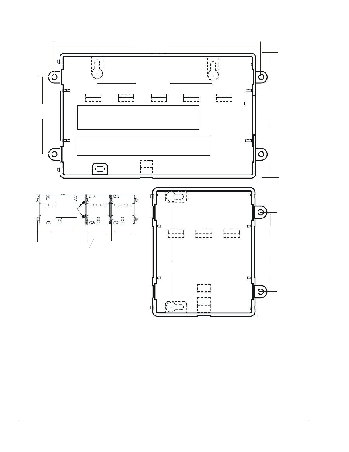
6.719 in. (170.66 mm)
0.170 in. Diame ter
( 4.3 2 mm)
FX-20/60
3.75 in. (95. 25 mm)
E l ectroni c and pri nted versions of this document may n ot show
2.5 0 i n.
(63.50 mm)
Note:
the d i m ensions to s cale. Verify all measur em ents bef or e drilling.
DIN mounting is recommended over ta b mounting.
4.0 0 i n.
(101.6 mm)
FX-20/60
Acc essory
module
side tabs
6. 719 in .
(170.66 mm)
Distan ce between center of tabs
fr o m on e u nit to anot he r un it .
TIP: If mounting accessory modules, future removal
or replacement of the FX-20/60 is simplified i f you
do not install screws in the accessory module side
tabs of the c ontroller (see above).
NDIO-16
3.2 5 i n.
(82.55 mm)
ND I O -1 6 or
LP-FXPM
3.2 5 i n.
(82.55 mm)
Figure 2: Tab Mounting Dimensions, in. (mm)
2.5 0 i n.
(63.50 mm)
NDIO-16
2.5 0 i n.
(63.50 mm)
6 FX20/60 Supervisory Controllers Installation Instructions
Page 7
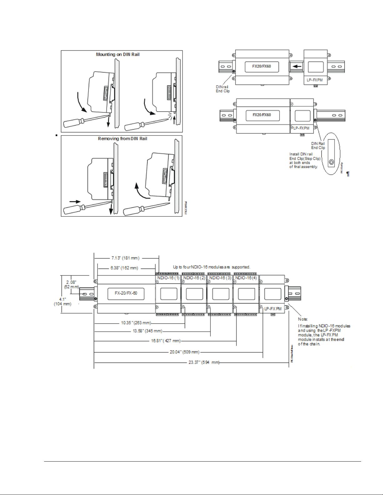
Figure 4: Using End Clips to Secure Modules
Figure 3: DIN Rail Mounting
Figure 5: Mounting Accessories
7 FX Supervisory Controller Installation Instructions
Page 8

Removing and Replacing the Cover
The FX20/FX60 cover is removable. You must remove
the FX20/FX60 cover to connect the battery on a new
unit, to replace the battery on an existing unit or to
install any optional communication cards. The cover
snaps onto the base with four plastic tabs (two on
each end). To remove the cover, press in the four tabs
on both ends of the unit and lift off the cover.
Note: If accessory modules are plugged into the
FX20/FX60, you may need to slide them away from
the unit to get to the cover tabs.
To replace the cover, position it so the cutout area for
the communication ports is correct, then push inward
to snap in place.
Serial port LEDs on bott om
Option Slot 2
Bat te r y Br a cket
(on t o p of optio n
cards, if any)
board; r emove cover to see.
COM1
COM2
Board Layout
See Figure 6 for the location of Light-Emitting Diodes
(LEDs), option slots, and other features of the
FX20/FX60. See Figure 9 for a side view of
communication ports and other features.
Status
Beat
Mode Jumper (for
serial shell access)
20-pin
connector
(I/O and
power
modules)
LAN2
LAN1
Battery
Connector
Option Slot
Connectors
Option Slot 1
RS-485 (3-positi on)
COM2 (bot tom board)
Secondary Ethernet (RJ-45)
LAN2 (t op board)
RS-232 (D-9)
COM1
Primary Ether ne t (RJ -45)
LAN1 (top board)
Figure 6: FX20/FX60 Board Layout Details
FIG :BrdL yt
Earth ground
spade l ug
Barrel pow e r
connector for
wall mounted
power module.
8 FX20/60 Supervisory Controllers Installation Instructions
Page 9

Expansion Options
The FX20/FX60 provides for field-installable expansion
with two options:
Option Cards: these are installed on connectors
inside the FX20/FX60 base unit. See Option
Cards.
Accessory Modules: these are chained onto the
FX20/FX60’s 20-pin connector. See Accessories.
Option Cards
The FX20/FX60 has 2 options slots for custom option
cards designed for use with the
FX20/FX60. Each slot has a 20-pin connector on the
FX20/FX60 base unit.
Table 2: Option Card Details
!
CAUTION: Risk of Property Damage.
Do not apply power to the system before checking
all wiring connections. Short circuited or improperly
connected wires may result in permanent damage to
the equipment.
MISE EN GARDE: Risque dégâts matériels.
Ne pas mettre le système sous tension avant d'avoir
vérifié tous les raccords de câblage. Des fils formant
un court-circuit ou connectés de façon incorrecte
risquent d'endommager irrémédiablement
l'équipement.
IMPORTANT: Be careful to plug an option card into
the connector properly with its pins properly aligned.
Option cards typically provide additional
communication capabilities, such as those listed in
Table 2. For a list of supported COM port and slot
assignments for the option cards, see Table 3.
Model Description Number of Option Cards Allowed per Controller
LP-FXLONFTT-1
LP-FXRS485-0
LP-FXMDM-0
LP-FXRS232-0
LP-FXWTC-0
LP-FXSED-0
LP-FXGPRS-0
LP-FXGPRSW-0
* If a modem card is installed, and the mode jumper is put in Serial Shell position (see Figure 6), then the FX20/FX60 base
RS-232 port becomes active immediately following a reboot. This allows an RS-232 conn ection to the se rial shell for
debugging purposes. To re-enable the modem, you must put the mode jumper back in the Normal position and reboot.
ONWORKS FTT-10A adapter with a
L
2-position removable screw terminal
plug
Dual, optically isolated, RS-485 adapter
with two 3-position removable screw
terminal connector plugs
56 Kbps auto-dial/auto-answer modem
with one RJ-11 connector for phone line
Single port RS-232 adapter, with a
DB-9M connector
Wireless TEC Card (WTC) with direct
mount antenna
Sedona Framework™ option card One
GPRS Modem card One
GPRS Modem option card with
Wyless™ SIM card
One or two
One or two
One*
One or two
One
One
FX Supervisory Controller Installation Instructions 9
Page 10

Table 3: COM Port and Option Slot Assignments for FX20/FX60 Option Cards
Option Slot 1 Option Slot 2 Onboard RS232 Onboard RS485
None None COM1 COM2
RS-232 = COM3 None COM1 COM2
RS-232 = COM3 RS-232 = COM4 COM1 COM2
RS-232 = COM3 RS-485 = COM4, COM5 COM1 COM2
RS-232 = COM3 LON = LON1 COM1 COM2
RS-232 = COM3 Sedona = COM4 COM1 COM2
RS-232 = COM3 GPRS = COM4,COM5 COM1 COM2
RS-485 = COM3, COM4 None COM1 COM2
RS-485 = COM3, COM4 RS-232 = COM5 COM1 COM2
RS-485 = COM3, COM4 RS-485 = COM5, COM6 COM1 COM2
RS-485 = COM3, COM4 LON = LON1 COM1 COM2
RS-485 = COM3, COM4 Sedona = COM5 COM1 COM2
RS-485 = COM3, COM4 GPRS = COM5, COM6 COM1 COM2
LON = LON1 None COM1 COM2
LON = LON1 RS-232 = COM3 COM1 COM2
LON = LON1 RS-485 = COM3, COM4 COM1 COM2
LON = LON1 LON = LON2 COM1 COM2
LON = LON1 Sedona = COM3 COM1 COM2
LON = LON1 GPRS = COM3, COM4 COM1 COM2
Wireless TEC = COM1 None Disabled COM2
Wireless TEC = COM1 RS-232 = COM3 Disabled COM2
Wireless TEC = COM1 RS-485 = COM3, COM4 Disabled COM2
Wireless TEC = COM1 LON = LON1 Disabled COM2
Wireless TEC = COM1 Sedona = COM3 Disabled COM2
Wireless TEC = COM1 GPRS = COM3, COM4 Disabled COM2
Sedona = COM3 None COM1 COM2
Sedona = COM3 RS-232 = COM4 COM1 COM2
Sedona = COM3 RS-485 = COM4, COM5 COM1 COM2
Sedona = COM3 LON = LON1 COM1 COM2
Sedona = COM3 GPRS = COM4,COM5 COM1 COM2
Modem = COM1 None Disabled COM2
Modem = COM1 RS-232 = COM3 Disabled COM2
Modem = COM1 RS-485 = COM3, COM4 Disable d COM2
Modem = COM1 LON = LON1 Disable d COM2
Modem = COM1 Sedona = COM3 Disabled COM2
Modem = COM1 GPRS = COM3, COM4 Disabled COM2
GPRS = COM3, COM4 None COM1 COM2
GPRS = COM3, COM4 RS-232 = COM5 COM1 COM2
GPRS = COM3, COM4 RS-485 = COM5, COM6 COM1 COM2
GPRS = COM3, COM4 LON = LON1 COM1 COM2
GPRS = COM3, COM4 SEDONA = COM5 COM1 COM2
10 FX20/60 Supervisory Controllers Installation Instructions
Page 11

Mounting Option Cards
For complete details, refer to the specific mounting
and wiring guide that shipped with the option card.
Follow these basic steps:
1. Remove power from the FX20/FX60.
2. Remove the cover.
3. Remove the battery and bracket assembly by
taking out the four screws holding it in place. Set
the screws aside for later. Unplug the battery from
the connector on the FX20/FX60.
4. Remove the blanking end plate for the slot into
which you are installing the option card. Retain the
blanking plate in case you need to remove the
option card at a later time.
5. Carefully insert the pins of the option card into the
socket of the appropriate option card slot. The
mounting holes on the option card should line up
with the standoffs on the base unit. If they do not,
the connector is not properly aligned. Press until
the option card is completely seated.
6. Place the custom end plate that came with the
option card over the connector(s) of the option
card.
7. Insert the battery connector plug into the battery
connector on the FX20/FX60.
8. Set the battery and bracket assembly back over
the option card slots, with the mounting holes
aligned with the standoffs.
9. Place the four screws through the battery bracket,
end plates, and into the standoffs on the
FX20/FX60 base unit. Hand-tighten these screws.
10. Replace the cover.
Wiring
See Figure 6 to locate connectors and other
components on the FX20/FX60.
Make connections to the FX20/FX60 in the following
order.
1. Install any option cards (LON, RS-232, RS-485,
modem, WTC) in Option Slots 1 and 2. See
Mounting Option Cards for the general procedure.
For complete details, refer to the specific mounting
and wiring guide that shipped with the option card.
2. Connect supplied earth grounding wires (with
spade connector) from the earth ground lug on the
FX20/FX60 and any accessory modules (if used)
to a nearby earth grounding point. See Grounding
for details.
3. Prepare power wiring (leave the unit powered off).
See Power Wiring for details.
4. Connect communications cables. See
Communications Wiring for ports available on the
FX20/FX60 base unit. For ports on any installed
option card (LON, RS-232, RS-485, modem, and
WTC), refer to the specific mounting and wiring
guide for additional details.
5. If NDIO modules are installed, connect the I/O
wiring. Refer to the appropriate mounting and
wiring guide for complete details.
6. Connect the backup battery to the FX20/FX60
battery connector, and apply power to the unit.
See Powerup and Initial Checkout.
Grounding
An earth ground spade lug (0.187 in. [4.75 mm]) is
provided on the base of the FX20/FX60 for connection
to earth ground. For maximum protection from
electrostatic discharge or other forms of
electromagnetic interference, connect the supplied
earth grounding wire to this lug and a nearby earth
ground (see Figure 7). Keep this wire as short as
possible.
Power is provided for the FX20/FX60 plug-in
accessory modules through the 20-pin accessory
connectors; however, connect the earth ground spade
lug of each accessory module to ground in the same
manner.
FX Supervisory Controller Installation Instructions 11
Page 12

Power Wiring
The FX20/FX60 must be powered by an approved 15
VDC power source. This can come from one of the
following:
an external wall mount AC adapter
(LP-FXPMUS/EU/UK-0)
a DIN rail mount 24 VAC/DC powered module
(LP-FXPM24-0)
a DIN rail mount line voltage
(90-263 VAC) module (LP-FXPM263-0)
an NDIO34 module (LP-FXNDIO34-0)
The FX20/FX60 does not include an on/off switch. To
apply power, you can do one of the following:
plug in the power connector to the FX20/FX60, if
the wall mount power module is used
plug in its 2-position power connector, if the
24 VAC DIN rail power supply is used
energize the AC circuit (90-263 VAC) wired to that
module, if the line voltage DIN rail power supply is
used
!
CAUTION: Risk of Property Damage.
Do not apply power to the system before checking
all wiring connections. Short circuited or improperly
connected wires may result in permanent damage to
the equipment.
Wall Mount Power Module
Three models of wall power modules are available:
United States (U.S.), European Union (EU), and
United Kingdom (U.K.). All are self-contained, isolated
switching power supplies designed to plug into a
standard building power receptacle for appropriate
voltage. To supply power to the FX20/FX60, you
simply plug the barrel connector plug from the power
module into the barrel power connector on the
FX20/FX60 base unit (see Figure 9).
IMPORTANT: Do not plug the barrel connector plug
from the power module into the FX20/FX60 until all
other mounting and wiring is completed.
Wiring LP-FXPM24-0 Power Module
The LP-FXPM24-0 module lets you power the
FX20/FX60 (and, if installed, the NDIO16 modules)
from a dedicated, Class 2, 24 VAC transformer, or
from a 24 VDC power supply. If installing NDIO16
modules, install the power module as the last (end)
module in the chain. See Figure 5.
IMPORTANT: If powering from a 24 VAC
transformer, do not power any other equipment with
it. Otherwise, conducted noise problems may result.
Also, do not ground either side of the transformer’s
secondary.
MISE EN GARDE: Risque dégâts matériels.
Ne pas mettre le système sous tension avant d'avoir
vérifié tous les raccords de câblage. Des fils formant
un court-circuit ou connectés de façon incorrecte
risquent d'endommager irrémédiablement
l'équipement.
If desired, you can use the wall mount power adapter
in your office to initially commission the FX20/FX60,
and then install the DIN rail mount power supply at the
project site.
12 FX20/60 Supervisory Controllers Installation Instructions
Page 13

LP-FXPM
(cover removed)
FX-20/FX-60
Dedicated 24 VA C transformer
Neither side of secondary tied
to earth ground.
Line volta ge
(Mains)
24 VAC
Figure 7: LP-FXPM Power Module Wiring Connections
Located at the bottom of the power module is a
2-position power connector and an earth ground spade
lug (see Figure 7). Connect the supplied earth ground
wire to a nearby earth ground point. Unplug the power
connector plug from the module and make
connections to it as shown in Figure 7.
!
CAUTION: Risk of Property Damage.
Do not apply power to the system before checking
all wiring connections. Short circuited or improperly
connected wires may result in permanent damage to
the equipment.
MISE EN GARDE: Risque dégâts matériels.
Ne pas mettre le système sous tension avant d'avoir
vérifié tous les raccords de câblage. Des fils formant
un court-circuit ou connectés de façon incorrecte
risquent d'endommager irrémédiablement
l'équipement.
Power consumption depends on installed accessories
and option cards, and may vary from:
Earth Ground
24 VDC Pow er S upp ly
(polarity not critical)
Neither side tied to
earth ground.
OR
24 VDC
FIG:BrdLyt
LP-FXPM263-0 Line Voltage Power Module
Using the LP-FXPM263-0 module lets you power the
FX20/FX60 (and, if installed, the NDIO16 modules)
from AC line power, with a universal input range from
90-263 VAC. If installing NDIO16 modules, install the
power module as the last (end) module in the chain
(see Figure 5).
!
WARNING: Risk of Electric Shock.
Disconnect power supply before making electrical
connections. Contact with components carrying
hazardous voltage can cause electric shock and
may result in personal injury or death.
AVERTISSEMENT: Risque de décharge
électrique. Débrancher l'alimentation avant de
réaliser tout branchement électrique. Tout contact
avec des composants conducteurs de tensions
dangereuses risque d'entraîner une décharge
électrique et de provoquer des blessures graves,
voire mortelles.
FX20/FX60 with power module alone: approximately
8.5 VA (AC) or 8.5 W (DC)
FX20/FX60 with power module and 4 NDIO modules,
plus option cards: up to 20 VA (AC) or 20 W (DC)
13 FX Supervisory Controller Installation Instructions
Note: The 6-pin connector of the LP-FXPM263-0 is
not used with a FX20/FX60.
Page 14

.
Remove cover
FX-20/FX-60 or
last NDIO-16.
120 or 240 VAC
50-60 Hz
Single Phase
Line
Neutral
L N
Figure 8: LP-FXPM263-0 Line Voltage Power Module Wiring Connections
To wire the DIN rail mount line voltage power module,
see Figure 8 and follow these instructions:
1. Remove power from the AC circuit being wired to
the power module.
2. Remove the power module cover by pressing in
the 4 tabs on both ends of the unit, and lifting the
cover off. If the power module is plugged into the
FX20/FX60 or an NDIO16, you may need to slide
it away to access the cover tabs.
3. Connect the supplied earth grounding wire to a
nearby grounding point (see Figure 8).
4. Make AC circuit connections line (mains) and
neutral to the terminals labeled INPUT PWR.
6-pin
connector
not used.
AC Input
Earth Ground
FIG:LnePwrModWr ng
!
CAUTION: Risk of Property Damage.
Do not apply power to the system before checking
all wiring connections. Short circuited or improperly
connected wires may result in permanent damage to
the equipment.
MISE EN GARDE: Risque dégâts matériels.
Ne pas mettre le système sous tension avant d'avoir
vérifié tous les raccords de câblage. Des fils formant
un court-circuit ou connectés de façon incorrecte
risquent d'endommager irrémédiablement
l'équipement.
5. Replace the cover on the power module.
6. Make sure that all modules in the assembly are
firmly connected together and secured.
14 FX Supervisory Controller Installation Instructions
Page 15

Communications Wiring
Connect communications wiring to the ports on the
bottom of the FX20/FX60.
Battery in bracket
(on top of option
car d s, if any )
Battery
Connector
Option Slot area
(Slot #1 this side)
Ethernet (RJ-45)
LAN 2
Figure 9: FX20/FX60 Bottom Side (Cover Removed)
Ethernet Port
Two female 10/100-Mbit Ethernet connections are
provided on the FX20/FX60. These connections are
capable of running at either 10 Mbps or 100 Mbps; the
controller automatically adjusts to either speed. This
means the FX20/FX60 can exist on the same network
with a mixture of 10BaseT and 100BaseTX hardware
connected to a smart 10/100 hub capable of adjusting
to the devices it supports.
Two RJ-45 connectors labeled LAN1 and LAN2 are
provided for the Ethernet connections (Figure 9). Use
a standard Ethernet patch cable for connecting to a
hub or Ethernet switch. An activity LED for each
Ethernet port is visible, labeled LAN1 and LAN2 on the
cover.
The factory default IP address for LAN1 is
192.168.1.149. By default, LAN2 is disabled.
Note: Typically, you only use LAN1 (primary port). If
you have a specific application for isolating a driver’s
network traffic to a separate local area network (LAN),
you can use LAN2. Do not use LAN2 as the primary
port.
Prior to connecting cables, provide strain relief for
them to prevent damage to the controller.
Primary Ethernet (RJ-45)
RS-232
(DB-9)
COM1
LAN 1
RS-485
(3-position)
COM2
Barrel power
connector for
power module
20-pin
Connector
(I/O and Pow er
Modules)
FIG :FX20_BtmSde
Earth Ground
Spade Lug
Serial Ports
The FX20/FX60 has two serial ports (see Figure 9).
Each port has a Universal Asynchronous Receive
Transmit (UART) capable of operation of up to
115,200 baud. The left port is an RS-232 port that
requires a DB-9 male plug connector. The right port is
a non-isolated RS-485 port that uses two wires with a
shield connection and a screw-terminal connector
plug. In addition, the FX60 controller has a standard
Universal Serial Bus (USB) port (not shown).
Note: A green receive LED and yellow transmit LED
are provided for each serial port. These LEDs are
located on the bottom board opposite of the serial
connectors (see Figure 6). The LEDs are labeled on
the board (COM1, COM2) and are not visible with the
cover on.
RS-232 Port
An RS-232 serial port uses a DB-9 male connector
and always operates as COM1. You can use a
standard DB-9 serial cable with this port. The
FX20/FX60 is a serial Data Terminal Equipment (DTE)
device, so connecting another DTE device (computer)
requires a null modem cable. To connect the
FX20/FX60 to a Data Communication Equipment
(DCE) device (modem), use a straight-through cable.
Table 4 provides the standard serial DB-9 pinouts.
FX Supervisory Controller Installation Instructions 15
Page 16

Table 4: Serial Port Pinouts
Pinout References Signal DB-9
DB-9 Plug (Male)
1
6
5
FIG:DB-9
9
DCD Data carrier detect 1
RXD Receive data 2
TXD Transmit data 3
DTR Data terminal ready 4
GND Ground 5
DSR Data set ready 6
RTS Request to send 7
CTS Clear to send 8
Not used on the FX20/FX60 9
RS-485 Port
Setup and Adjustments
An RS-485 non-isolated port uses a 3-position, screw
terminal connector and always operates as COM2.
Use shielded 18-22 AWG wire for this connector (refer
to the Telecommunications Industry
Default Communication and Login Properties
The new FX20/FX60 are pre-configured with default
properties as defined in Table 5.
Association/Electronic Industries Alliance
[TIA/EIA-485 standard]). As shown in Table 4, the
screw terminals (from left to right) are shield, plus (+),
and minus (–).
USB Port (FX60 only)
A single USB port is on the top of the FX60.
Note: The USB port is for future use. Do not use the
port at this time.
Table 5: FX20/FX60 Default Properties
Name Default Property
Internet Protocol (IP)
Address
Subnet Mask
Default Gateway
Remote User Name
Remote Password
Plug Pin
Base RS-485
Port (COM2)
Pinouts
S + -
192.168.1.149
255.255.255.0
192.168.1.1
jci
explorer
FIG:3pos
Powerup and Initial Checkout
Ensure that power wiring to the transformer is
complete before you proceed (see Power Wiring). See
Figure 6 for locations of the battery connector, status
LEDs, and barrel power connector. See Figure 7 for
location of the power connector on the DIN rail power
modules.
After you have completed all mounting and wiring
steps:
1. Connect the backup battery.
2. Apply power.
Check the status LEDs.
16 FX20/60 Supervisory Controllers Installation Instructions
Page 17

Connecting the Backup Battery
With the cover removed from the FX20/FX60, locate
the red and black wires with a plug on the backup
battery. Insert the plug into the battery connector on
the bottom board as shown in Figure 10.
Battery
Assembly
Battery
Connector
FIG :Bcku pB att
Figure 10: Backup Battery Connector Location
The connector is keyed so you cannot insert it
incorrectly. The red (positive) connection should be the
furthest from the two 30-pin option board connectors.
For more battery details, see About the Battery.
Operation
Apply power to the FX20/FX60 by plugging in the
power plug into either the FX20 (if using the wall
mount power module) or the 24 VAC/DC power
module. If the controller is using the line voltage power
module, energize the 90-263 VAC circuit.
About the Battery
The FX20/FX60 is provided with a custom, 10-cell
NiMH battery pack mounted to the unit under the
cover. This battery allows the FX Supervisory to
continue operation through very short power
interruptions (a few seconds in duration). If a longer
power outage occurs, the battery provides enough run
time for the FX Supervisory to backup data and then
shutdown. Typically, this takes 1 minute to complete.
Shutdown occurs automatically, after data is backed
up to onboard flash memory.
The FX20/FX60 charges the battery during normal
operation, until fully charged. Typically, the charge
operation completes within 18 hours. Following a
power outage, the battery is charged again, as
necessary. The power and battery circuitry is
monitored by a station running on the FX20/FX60 (via
the PowerMonitorService). Station alarms are
generated when primary power is lost, or if the battery
is uncharged or unable to hold a sufficient charge.
The battery should be replaced about every 3 years. If
the unit is in a high temperature environment, replace
it more often.
Note: The NiMH battery looses its charge if not left
in trickle-charge mode. If you leave the battery
disconnected or attached to the unit when powered off,
the battery fully discharges in a matter of weeks. A
new FX20/FX60 ships from the factory with a
completely discharged battery; after installation, allow
at least 18 hours for the battery to fully charge.
Using Status LEDs
The FX20/FX60 includes several LEDs that can help
determine the status of the unit. These LEDs include:
IMPORTANT: Do not connect both the wall power
module and the DIN rail power modules at the same
time, or equipment damage will result, or a power
outage may go unrecognized.
Checking the Status LEDs
When power is applied, the green LED labeled Status
is lit. This indicates that the system is normal and
power is applied. Once the FX20/FX60 boots, the
yellow BEAT (heartbeat) LED begins to blink, with a
typical rate of about one blink per second. Blinking
should begin within 30 seconds after power is applied.
If, after applying power, the STATUS LED goes out, or
the BEAT LED comes on steady and stays lit for
longer than 2 minutes, contact your technical support
representative for assistance. See also Using Status
LEDs.
Ethernet Ports
Heartbeat
Status
Serial Ports
Refer to Figure 6 for the location of the status LEDs.
Ethernet Ports LEDs
Each Ethernet port has one green LED, visible on the
top cover. A LAN# LED indicates activity on that port
as follows:
Off: No Ethernet link is established.
On: Ethernet link is established, but no activity is
on the LAN.
Blinking: Ethernet link is established with data
activity on the LAN.
FX Supervisory Controller Installation Instructions 17
Page 18

Heartbeat LED
The yellow BEAT LED is located to the right of the
Ethernet status LEDs. Under normal operation, this
LED should blink about once per second. If the BEAT
LED stays on constantly, does not light, or blinks very
fast (more than once per second), contact your
technical support representative for assistance.
IMPORTANT: During boot-up, the heartbeat LED
blinks in a 90% on, 10% off pattern. Do not remove
power during this time, or data loss may result
(NDIO module’s firmware upgrade may be in
progress).
Status LED
The green Status LED is located to the right of the
heartbeat (BEAT) LED. This LED provides a central
processing unit (CPU) machine status check, and
remains lit whenever the FX20/FX60 is powered. If the
Status LED does not light while power is applied,
contact your technical support representative for
assistance.
Serial Port LEDs
LEDs for the 2 serial ports are located on the
FX20/FX60’s bottom board on the opposite side of the
RS-232 and RS-485 ports (see Figure 6). Labels
COM1 and COM2 correspond to the software
configuration of the COM ports. LEDs show, transmit,
and receive activity for the serial ports and optional
modem.
Note: You must remove the cover to see the serial
port LEDs. See Removing and Replacing the Cover.
The yellow Transmit LED indicates that the
FX20/FX60 is sending data out the serial port over
a communications line to a connected device.
The green Receive LED indicates that the
FX20/FX60 is receiving data from a connected
device.
Niagara
AX
Software Installation
As shipped from the factory, FX20/FX60 are pre-
configured with a Niagara build, a license, and four
Johnson Controls® specific Java® Archive (JAR) files.
With these components in place, you only need to
change login credentials and IP settings (per network
requirements) when setting up the FX20/FX60. This
section provides step-by-step instructions for these
tasks.
The most straightforward way to set up an FX20/FX60
(and to upgrade to a newer Niagara build at a later
date) is to use the administrative tools available under
the Tools Menu in the FX Workbench software.
Note: If upgrading JAR files with patches at a later
date, use the Update Remote Site menu item. If
upgrading to a newer Niagara build, use the Upgrade
Remote Software Version menu item. If changing login
credentials, use the Change Remote Login Credentials
menu item.
Preparing for Setup
Providing Power and Connectivity
Perform the initial startup of an FX20/FX60 in your
office before physically mounting it in place at a job
site.
After you complete the commissioning process, mount
and wire the FX20/FX60 at the job site, making
permanent mounting and wiring connections.
For this initial Ethernet connection, you can use one of
the following:
a crossover cable connected directly between your
computer and the FX20/FX60
a standard Local Area Network (LAN) connection
in which your computer and the FX20/FX60 are
physically connected to the same Ethernet hub or
switch
These LEDs are driven by pulse detectors that provide
a fixed on-time sequence when data is detected on the
port. If the receive LED is on constantly, a problem
with the communications channel may be present,
such as a shorted wire or reversed wiring.
18 FX20/60 Supervisory Controllers Installation Instructions
Page 19

IP Address
When shipped, a new FX20/FX60 Series controller is
pre-configured with an IP address of 192.168.1.149
and a default subnet mask of 255.255.255.0.
To change the IP settings, perform the following steps:
1. Use the Microsoft®
Windows® Network
Connections utility on your workstation to
configure your Transmission Control Protocol
(TCP)/IP settings with an IP address of
192.168.1.100 and subnet mask of 255.255.255.0.
2. Make an Ethernet connection to the FX20/FX60
as indicated in Providing Power and Connectivity.
3. Run the FX Workbench application.
4. Under the File Menu, select the Open Remote
Station menu item. When prompted, enter the
Remote Site Address (192.168.1.149), Remote
Username (jci), and Remote Password
(explorer). Click OK. When the Authentication
dialog appears, enter the Username (admin),
leave the Password field empty, and click OK.
5. The station running on the FX20/FX60 opens with
the FX Workbench application, which has a
Navigation Tree on the left and a Display Window
on the right. In the Navigation Tree, open the
Administration folder. Double-click the TCP IP
Configuration option.
6. On the TCP/IP Configuration screen, make sure
the Interfaces field is expanded so that the IP
Address and Subnet Mask fields appear. Modify
the Gateway, IP Address and Subnet Mask fields,
and click Save. When prompted to Reboot Now,
click Yes. Give the FX20/FX60 a couple of
minutes to reboot and restart the station that is
installed.
Note: If the following message appears, just click
OK. The changes are saved anyway.
Initially, you use these default credentials to open a
platform connection (log in) to the FX20/FX60. Like the
factory-assigned IP address, default credentials are
intended to be temporary. Change these credentials to
be something unique, and guard them closely.
To change the Platform Daemon credentials, perform
the following steps:
1. Start the FX Workbench application.
2. Under the File Menu, select the Open Remote
Station menu item. When prompted, enter the
Remote Site Address (for example,
192.168.1.149), Remote Username (jci), and
Remote Password (explorer). Click OK. When the
Authentication dialog appears, enter the
Username (admin), leave the password field
empty, and click OK.
3. Under the Tools menu, select Change Remote
Login Credentials. In the Change Remote Login
Credentials dialog, fill in the Username, Password,
and Confirm Password fields, then click OK. The
next time you log into the FX20/FX60, use these
new credentials.
Restoring a Backed Up Station
If the FX20/FX60 ever gets into an erroneous condition
where you cannot fix a station, you can restore a
previously backed up station by using the Restore
Backed Up Station menu item under the Tools menu.
To restore a backed up station, perform the following
steps:
1. Run the FX Workbench application.
2. Under the File Menu, select the Open Remote
Station menu item. When prompted, enter the
Remote Site Address (for example,
192.168.1.149), Remote Username (jci), and
Remote Password (explorer). Click OK. When the
Authentication dialog appears, enter the
Username (admin), Password (optional), and click
OK.
Platform Daemon Credentials
An FX20/FX60 Series controller is shipped with the
following Platform Daemon (Administrator) credentials:
User Name: jci
Password: explorer
3. Under the Tools menu, select Restore Backed Up
Station. In the Restore Backed Up Station dialog,
enter the Remote Site IP Address, Remote
Username, Remote Password, and select the .dist
(station backup) file. Click OK. The FX20/FX60
reboots automatically.
Note: You can back up a station by using the
Backup Station menu item from the station node’s
popup menu in the Navigation Tree. We
recommend that you back up a station daily to
minimize the chance of information loss.
FX Supervisory Controller Installation Instructions 19
Page 20

Cleaning
If dust or metal filings are present inside the unit, clean
with vacuum or compressed air. Otherwise, no
cleaning inside the unit is required. Optionally, if the
outer enclosure becomes dirty, you can wipe it with a
damp cloth and mild detergent.
Required Battery Maintenance
Battery life expectancy is a function of its discharge
cycles (the number of discharges and their depth) and
the ambient temperature of the battery during normal
operation. In most applications, the battery should see
relatively few discharges. Therefore, ambient
temperature has more to do with determining the life
expectancy of the battery than any other factor. If the
FX20/FX60 is installed in a conditioned space, the
battery should provide dependable service for
approximately 3 years. In an environment where the
operating temperature is higher (50ºC or 122ºF), you
should only expect the battery to last approximately
1 year.
The NiMH battery in the FX20/FX60 is fully discharged
before shipping. Additionally, NiMH batteries lose
charge over time if not kept trickle-charged. Therefore,
even a new unit (or replacement battery) requires up
to 18 hours of powered operation before it becomes
fully charged to provide reliable backup power.
The FX20/FX60 monitors the battery and periodically
loads the battery to test its ability to maintain
battery-backed functions. Investigate any battery
trouble message, and check the battery connections to
the unit. Replace the battery as required.
To order a new battery, see Standard Replacement
Parts.
Replacing the Battery
The replacement battery is a complete assembly,
consisting of a custom NiMH battery pack pre-attached
to a battery bracket (see Figure 10).
IMPORTANT: Use only NiMH battery packs
approved for use with the FX20/FX60.
4. Remove the old battery and bracket assembly by
removing the four screws holding it in place. Set
the screws aside for later.
5. Remove the battery from the connector on the
FX20/FX60.
6. Recycle the battery as defined by your regional
codes. For recycling within the United States, see
the battery label.
7. Plug the battery connector plug of the
replacement battery into the battery connector on
the FX20/FX60.
8. Place the replacement battery/bracket assembly
over the option card slots, with the mounting
holes aligned with the standoffs.
9. Place the four screws through the battery bracket,
option card blanking plates, option cards (if used),
and into the standoffs on the FX20/FX60 base
board. Using a screwdriver, hand-tighten these
screws.
10. Replace the cover.
11. Restore power to the FX20/FX60 and verify
normal operation.
Repair Information
Servicing the FX20/FX60 may call for replacement
parts.
Non-replaceable Parts
Other than the parts listed in the Standard
Replacement Parts section, no serviceable
components are on the base assembly.
Memory
Any addition, modification, or replacement of memory
components requires software configuration changes
and is not field upgradeable. For additional information
on modifying the memory capacity of the FX20/FX60,
consult your local sales representative.
To replace the battery:
1. Back up the FX20/FX60’s configuration to your
computer using FX Workbench.
2. Remove power from the FX20/FX60. Wait for
LED activity to stop. After several seconds, all
LEDs on the FX20/FX60 should be off.
3. Remove the cover. See Removing and Replacing
the Cover.
20 FX20/60 Supervisory Controllers Installation Instructions
Page 21

Fuse
The FX20/FX60 contains a non-user replaceable fuse
soldered on the circuit board. This fuse provides
protection from internal shorts or connection to
incorrect power supplies. If the fuse circuitry is
suspect, contact your technical support representative
for assistance.
Standard Replacement Parts
Standard replacement parts are listed in Table 6.
Table 6: Standard Replacement Parts
Part Number Description
LP-KITFX2BAT-0
NiMH Battery Pack: includes battery
bracket (See Replacing the Battery.)
New Replacement Unit
To replace a faulty FX20/FX60, order a new one. To
ensure proper credit for a FX20/FX60 still under
warranty, contact the Johnson Controls Product Sales
Operations Team for return authorization.
Replacing an FX20/FX60
IMPORTANT: Before handling circuit boards,
discharge any accumulated static by touching the
metal surface of the FX20/FX60.
To replace the FX20/FX60 in the field, follow these
procedures:
1. Use FX Workbench to back up the FX20/FX60
configuration to your computer.
2. Remove power to the FX20/FX60. The unit
powers down automatically.
Note: If NDIO accessory modules are installed, and
any I/O points have voltage, turn the devices off or
disconnect power from them.
a. If DIN rail mounting with DIN end clips were
used, you may be able to remove the DIN rail
end clip that secures the FX20/FX60 end of
the assembly and then slide the FX20/FX60
away from the rest of the assembly. Then,
remove the FX20/FX60 from the DIN rail (see
Figure 3), leaving the mounting and wiring of
the NDIO modules untouched. Go to Step 5.
b. If tab (screw) mounting was used instead of
DIN rail mounting, or if a combination of DIN
rail mounting and tab screws were used,
remove the accessory modules first, then
remove the FX20/FX60. Carefully observe all
wiring terminations, then unplug the I/O
connector plugs and earth ground wires from
the installed NDIO modules. Remove the
installed accessory modules, starting with the
end module. You can secure modules with
screws through the mounting tabs or clipped
to a DIN rail, or fastened by some
combination. Remove any screws fastening
the FX20/FX60 and remove the FX20/FX60.
5. Remove the cover from the old FX20/FX60 (see
Removing and Replacing the Cover). Note the
position of installed option boards, if any. You
must transfer them to the replacement
FX20/FX60.
6. Remove the option boards from the old
FX20/FX60 and install them into the replacement
FX20/FX60, if applicable. See Mounting Option
Cards.
7. Mount the replacement FX20/FX60 as it was
previously, using the same DIN rail location
and/or screws.
8. Reconnect/remount any removed accessory
modules, being careful to replace them in the
same order, using the same DIN rail location
and/or screws. Secure all accessory modules as
done previously.
1. Note the positions of all communications and other
wiring cables going to the FX20/FX60, as well as
all installed accessory modules (if they must be
removed). If necessary, label connectors and
accessory modules to avoid misconnection later
when you are replacing the FX20/FX60.
2. Unplug all Ethernet, serial, LON, modem, and I/O
connectors from the FX20/FX60.
3. Unplug the earth ground wire.
4. If an NDIO accessory module is installed:
9. Reconnect the earth ground wires to the
FX20/FX60 grounding lug and any installed
accessory modules.
FX Supervisory Controller Installation Instructions 21
Page 22

10. Reconnect any Ethernet, serial, modem, and I/O
connectors to the FX20/FX60 and any installed
accessory modules.
11. If using NDIO modules, and if any of your I/O
points have voltage, turn on the devices or
reconnect power to them.
12. Restore power to the FX20/FX60. To verify
operation, see Checking the Status LEDs.
13. Use FX Workbench to recommission the
FX20/FX60 and install the saved station
database.
Johnson Controls® is a registered trademark of Johnson Controls, Inc.
All other marks herein are the marks of their respective owners. © 2014 Johnson Controls, Inc.
22 FX20/60 Supervisory Controllers Installation Instructions
Building Efficiency
507 E. Michigan Street, Milwaukee, WI 53202
 Loading...