

Page 1

FAC3613 Advanced Application Field Equipment
Application
The FAC3613 Advanced Application Field Equipment
Controller (FAC) is part of the Metasys® system
Field Equipment Controller family. The FAC36
Series controllers run pre-engineered and userprogrammed applications and provides the inputs
and outputs required to monitor and control a wide
variety of HVAC and other facility equipment.
FAC36 controllers operate on an RS-485 BACnet
MS/TP Bus as BACnet Advanced Application
Controllers (B-AACs) and integrate into Johnson
Controls® and third-party BACnet systems.
FAC36 field controllers include an integral real-time
clock, which enables the controllers to monitor
and control schedules, calendars, and trends, and
operate for extended periods of time as stand-alone
controllers when offline from the Metasys system
network.
Communications protocols
The FAC3613 field controllers can communicate
using BACnet MS/TP, N2, or wireless Zigbee. By
default, the FAC3613 field controllers communicate
using the standard BACnet MS/TP protocol. The
BACnet protocol is a standard for ANSI, ASHRAE, and
the International Standards Organization (ISO) for
building controls.
The FEC Family Controllers, including the FAC3613,
can be used as functional replacements for
legacy N2 controllers. The N2-capable MS/TP
field controller models provide a cost-effective
upgrade and modernization path for customers
with existing N2 controllers. For installation and
commissioning support, and tips for efficient and
safe replacement, refer to the Modernization Guide
for Legacy N2 Controllers (LIT-12012005) and the
controller-specific documentation. For information
about mapping N2 Objects in controllers with
switchable communications protocols, refer to the
N2 Compatibility Options chapter of the Controller Tool
Help (LIT-12011147).
To configure FAC3613 field controllers to
communicate using the N2 communications
protocol, see Configuring N2 Communications.
The FAC3613 field controller can also be installed in
a wireless application using a ZFR/ZFR Pro Wireless
Field Bus Router. To configure these controllers to
®
Controller Installation Guide
Part No. 24-11021-7 Rev. C
2019-10-18
communicate using the wireless communications
protocol, see Configuring Wireless Communications.
Fast persistence
The FAC3613 model has been significantly upgraded
and now includes a fast persistence feature that
allows you to retain data values at a configurable
interval, up to once per second. Persistence refers
to how often samples of data are stored locally. This
upgrade to the persistence feature ensures that
in the event of a problem, such as a loss of power,
more recent data can be retrieved up to the rate that
the data is persisted, minimizing the potential loss of
data. When power is restored, previously persisted
data, up to the rate of persistence, is still available
and accessible. When persistence is configured
for once per second, you risk losing only the most
recent one second of data before the power loss.
Persisting data may be essential for situations that
require greater data accuracy. This may include
certain methods of utility data collection and billing
Attributes that can be persisted in the FAC3613
include: Counter Input Present Value Attributes,
Binary Input, Binary Output, and Binary Value COS
Counts and Active Time Attributes, and PID/PRAC
tuning parameters.
North American emissions compliance
United States
This equipment has been tested and found to
comply with the limits for a Class A digital device
pursuant to Part 15 of the FCC Rules. These limits
are designed to provide reasonable protection
against harmful interference when this equipment
is operated in a commercial environment. This
equipment generates, uses, and can radiate radio
frequency energy and, if not installed and used in
accordance with the instruction manual, may cause
harmful interference to radio communications.
Operation of this equipment in a residential area
may cause harmful interference, in which case the
users will be required to correct the interference at
their own expense.
*24110217C*
(barcode for factory use only)
MS-FAC3613
Page 2
Canada
This Class (A) digital apparatus meets all the
requirements of the Canadian Interference-Causing
Equipment Regulations.
Cet appareil numérique de la Classe (A) respecte
toutes les exigences du Règlement sur le matériel
brouilleur du Canada.
• Do not drop the controller or subject it to physical
shock.
Parts included
• One field Controller. (Power and SA bus terminal
blocks are removable)
• One installation instructions sheet.
Installation
Observe the following guidelines when installing a
field controller:
• To minimize vibration and shock damage,
transport the controller in the original container.
• Verify that all parts shipped with the controller.
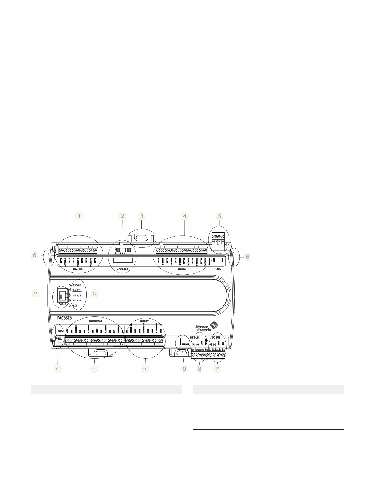
FAC3613 physical features
Figure 1: FAC3613 Physical Features
Materials and special tools needed
• Three fasteners appropriate for the mounting
surface (M4 screws or #8 screws)
• One 23 cm (9.125 in.) or longer piece of 35 mm
DIN rail and appropriate hardware for DIN rail
mount (only)
• Small straight-blade screwdriver for securing
wires in the terminal blocks
Table 1: Physical features
Physical feature: description and references
Analog Output (AO) Terminal Block: Can be defined as
1
Voltage Analog Output (0–10 VDC) or Current Analog
Output (4–20 mA) (see Table 2)
Device Address DIP Switch Block (see Setting the Device
2
Addresses)
3 Mounting clip
FAC3613 Advanced Application Field Equipment Controller Installation Guide2
Table 1: Physical features
Physical feature: description and references
Binary Outputs (BO) Terminal Block: 24 VAC Triac (see
4
Table 2)
24 VAC, Class 2/SELV Supply Power Terminal Block (see
5
Supply power terminal block)
6 Cover Lift Tab (One of Two)
7 FC Bus Terminal Block (see FC bus terminal block )
Page 3
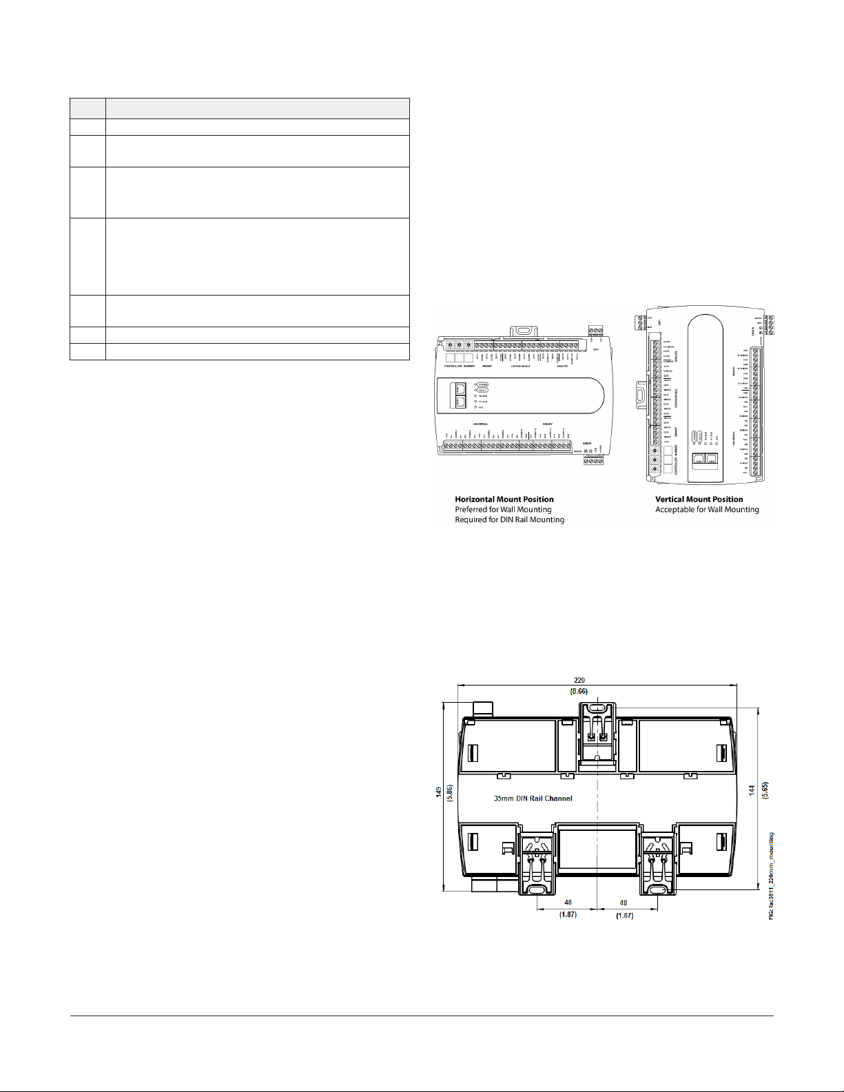
Table 1: Physical features
Physical feature: description and references
8 SA Bus Terminal Block (see SA bus terminal block)
Sensor Port: (SA Bus) RJ-12 6-Pin Modular Jack (see SA Bus
9
port )
Binary Input (BI) Terminal Block: Dry Contact Maintained
or Pulse Counter/Accumulator Mode (see Terminal wiring
10
guidelines, functions, ratings, and requirements
Universal Inputs (UI) Terminal Block: Can be defined as
Voltage Analog Input (0–10 VDC), Current Analog Input
11
(4–20 mA), Resistive Analog Inputs (0–600k ohms), or
Dry Contact Binary Input (see Input and Output wiring
guidelines)
End-of-Line (EOL) Switch (see Setting the End-of-Line
12
(EOL) switch)
13 LED Status Indicators (see Table 7)
14 FC Bus Port (RJ-12 6-pin Modular Jack)
Mounting
Observe the following guidelines when mounting a
field controller:
• Ensure the mounting surface can support the
controller, DIN rail, and any user-supplied
enclosure.
Observe these additional guidelines when mounting
a field controller in a panel or enclosure:
• Mount the controller so that the enclosure walls
do not obstruct cover removal or ventilation
through the controller.
• Mount the controller so that the power
transformer and other devices do not radiate
excessive heat to the controller.
• Do not install the controller in an airtight
enclosure.
Figure 2: Controller Mounting Positions
• Mount the controller horizontally on 35 mm DIN
rail whenever possible.
• Mount the controller in the correct mounting
position (Figure 2).
• Whenever possible in wall-mount applications,
mount the controller on a hard, even surface.
• Use shims or washers to mount the controller
securely and evenly on the mounting surface.
• Mount the controller in an area free of corrosive
vapors and observe the ambient conditions
requirements in Technical specifications.
• Provide sufficient space around the controller for
cable and wire connections, easy cover removal,
and good ventilation through the controller (50
mm [2 in.] minimum on the top, bottom, and
front of the controller).
• Do not mount the controller on surfaces prone to
vibration, such as ductwork.
• Do not mount the controller in areas where
electromagnetic emissions from other
devices or wiring can interfere with controller
communication.
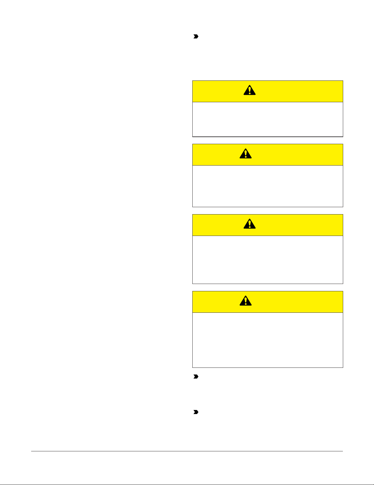
Mounting Features and Dimensions
See Figure 3 for mounting dimensions in millimeters
and inches. Inches are listed in parenthesis. Figure
3 also illustrates the DIN rail channel and the
mounting clips in an extended position.
Figure 3: Back of Controller
FAC3613 Advanced Application Field Equipment Controller Installation Guide 3
Page 4
DIN Rail mount applications
Mounting the field controller horizontally on 35 mm
DIN rail is the preferred mounting method.
To mount a field controller on 35 mm DIN rail,
complete the following steps:
Important: Do not overtighten the mounting
screws. Overtightening the screws may
damage the mounting clips.
Wiring
1. Securely mount a 23 cm (9.125 in.) or longer
section of 35 mm DIN rail, horizontally and
centered in the desired space, so that the
controller mounts in the position shown in
Figure 2.
2. Pull the two bottom mounting clips outward
from the controller to the extended position
(Figure ).
3. Hang the controller on the DIN rail by the hooks
at the top of the (DIN rail) channel on the back
of the controller (Figure ), and position the
controller snugly against the DIN rail.
4. Push the bottom mounting clips inward (up) to
secure the controller on the DIN rail.
To remove the controller from the DIN rail, pull the
bottom mounting clips out to the extended position
and carefully lift the controller off the DIN rail.
Wall mount applications
To mount a field controller directly on a wall or
other flat vertical surface, complete the following
steps:
CAUTION
Risk of Electric Shock:
Disconnect the power supply before making electrical
connections to avoid electric shock
ATTENTION
Mise En Garde: Risque de décharge électrique
Débrancher l'alimentation avant de réaliser tout raccordement électrique afin d'éviter tout risque de
décharge électrique.
CAUTION
Risk of Property Damage:
Do not apply power to the system before checking all
wiring connections. Short circuited or improperly connected wires may result in permanent damage to the
equipment.
1. Pull the two bottom mounting clips outward
and ensure they are locked in the extended
position.
2. Mark the mounting hole locations on the wall
in either the horizontal or vertical mounting
position. Or hold the controller up to the wall or
surface in a proper mount position and msark
the hole locations through the mounting clips.
3. Drill holes in the wall or surface at the marked
locations, and insert appropriate wall anchors
in the holes (if necessary).
4. Hold the controller in place, and insert the
screws through the mounting clips and into the
holes (or anchors). Carefully tighten all of the
screws.
FAC3613 Advanced Application Field Equipment Controller Installation Guide4
ATTENTION
Mise En Garde: Risque de dégâts matériels
Ne pas mettre le système sous tension avant d'avoir
vérifié tous les raccords de câblage. Des fils formant un court-circuit ou connectés de façon incorrecte risquent d'endommager irrémédiablement
l'équipement.
Important: Do not exceed the controller
electrical ratings. Exceeding controller electrical
ratings can result in permanent damage to the
controller and void any warranty.
Important: Use copper conductors only. Make
all wiring in accordance with local, national, and
regional regulations.
Page 5
Important: Electrostatic discharge can
damage controller components. Use proper
electrostatic discharge precautions during
installation, setup, and servicing to avoid
damaging the controller.
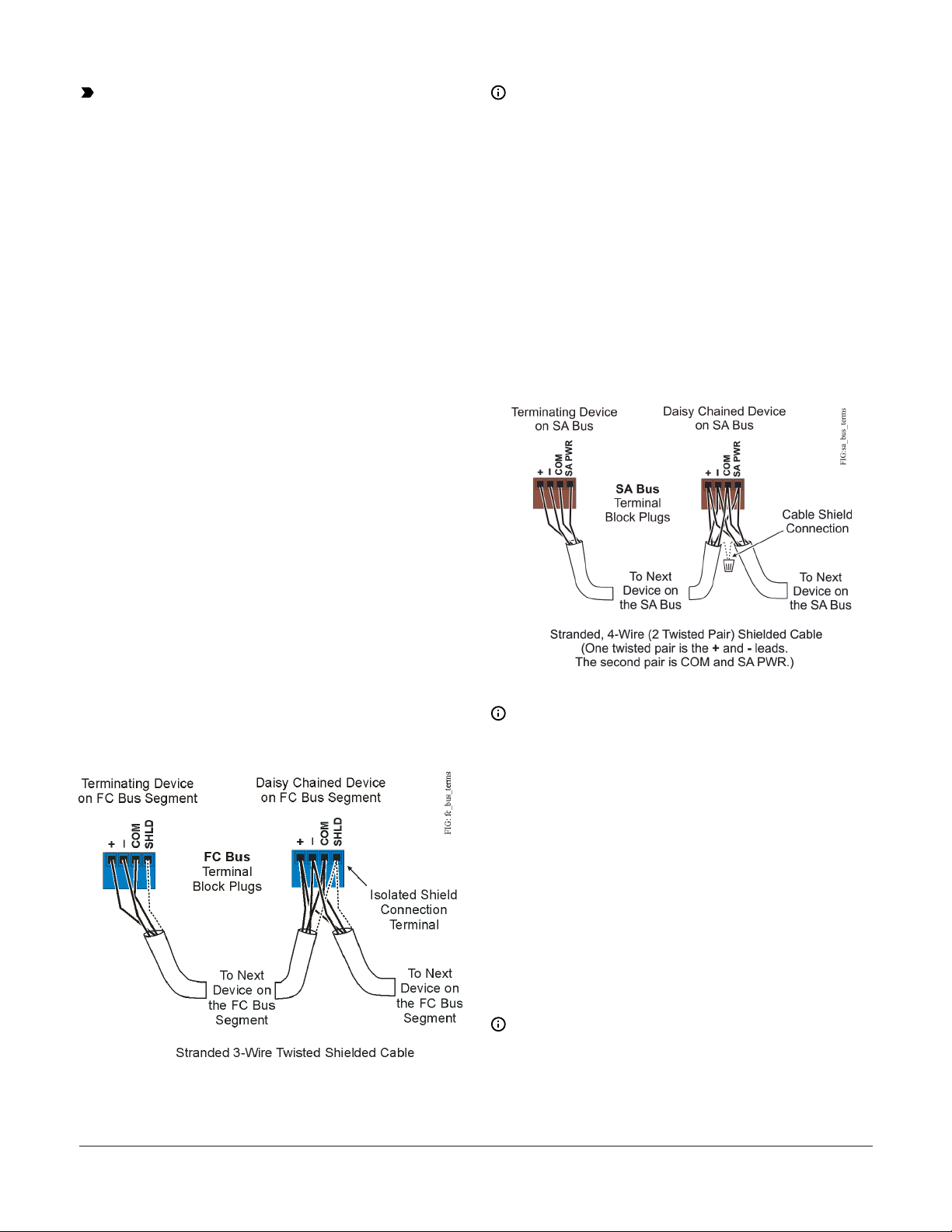
Note: The FC bus Shield (SHLD) terminal is
isolated and can be used to connect (daisy
chain) the shields for FC bus wiring.
SA bus terminal block
For detailed information about configuring and
wiring an MS/TP bus, FC bus and SA bus, refer to
the MS/TP Communications Bus Technical Bulletin
(LIT-12011034). For detailed information on wiring an
N2 network, refer to the
Terminal blocks and bus ports
See FAC3613 physical features for terminal block
and bus port locations on the FAC3613 controller.
Observe the following guidelines when wiring a
controller.
Input and Output terminal blocks
The fixed input terminal blocks are located on the
bottom of the controller, and the output terminal
blocks are located on the top of the controller. See
Table 2 for more information about I/O terminal
functions, requirements, and ratings.
FC bus terminal block
The FC Bus terminal block is a blue, removable, 4terminal plug that fits into a board-mounted jack.
Wire the removable FC bus terminal block plugs on
the controller, and other controllers in a daisy-chain
configuration using 3-wire twisted, shielded cable as
shown in Figure 4. For more information about the
FC Bus terminal function, requirements, and ratings,
see .
Figure 4: FC bus terminal block wiring
The SA Bus terminal block is a brown, removable, 4terminal plug that fits into a board-mounted jack.
Wire the removable SA Bus terminal block plugs on
the controller, and other SA bus devices in a daisychain configuration using 4-wire twisted, shielded
cable as shown in Figure 5. For more information
about the SA Bus terminal function, requirements,
and ratings, see .
Figure 5: SA bus terminal block wiring
Note: The SA PWR terminal supplies 15 VDC.
The SA PWR terminal can be used to connect
(daisy chain) the 15 VDC power leads on the SA
bus.
FC bus port
The FC bus port on the front of the controller is
an RJ-12, 6-position modular jack that provides
a connection for the Mobile Access Portal (MAP)
Gateway, the Bluetooth® Commissioning Converter,
or the ZFR/ZFR Pro Wireless Field Bus Router.
The FC bus port is connected internally to the FC bus
terminal block. For more information about the FC
Bus port functions, requirements, and ratings, see .
The FC bus port pin assignment is shown in Figure
6.
Note:
• When the is configured for N2 network
communication, the FC bus port is not used.
FAC3613 Advanced Application Field Equipment Controller Installation Guide 5
Page 6
• The MAP Gateway serves as a replacement
for the BTCVT, which is no longer available
for purchase, but continues to be supported.
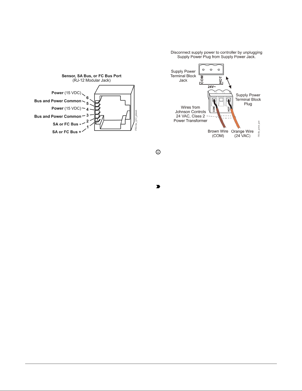
Figure 6: Pin number assignments for sensor, SA
bus, and FC bus ports on Field Controllers
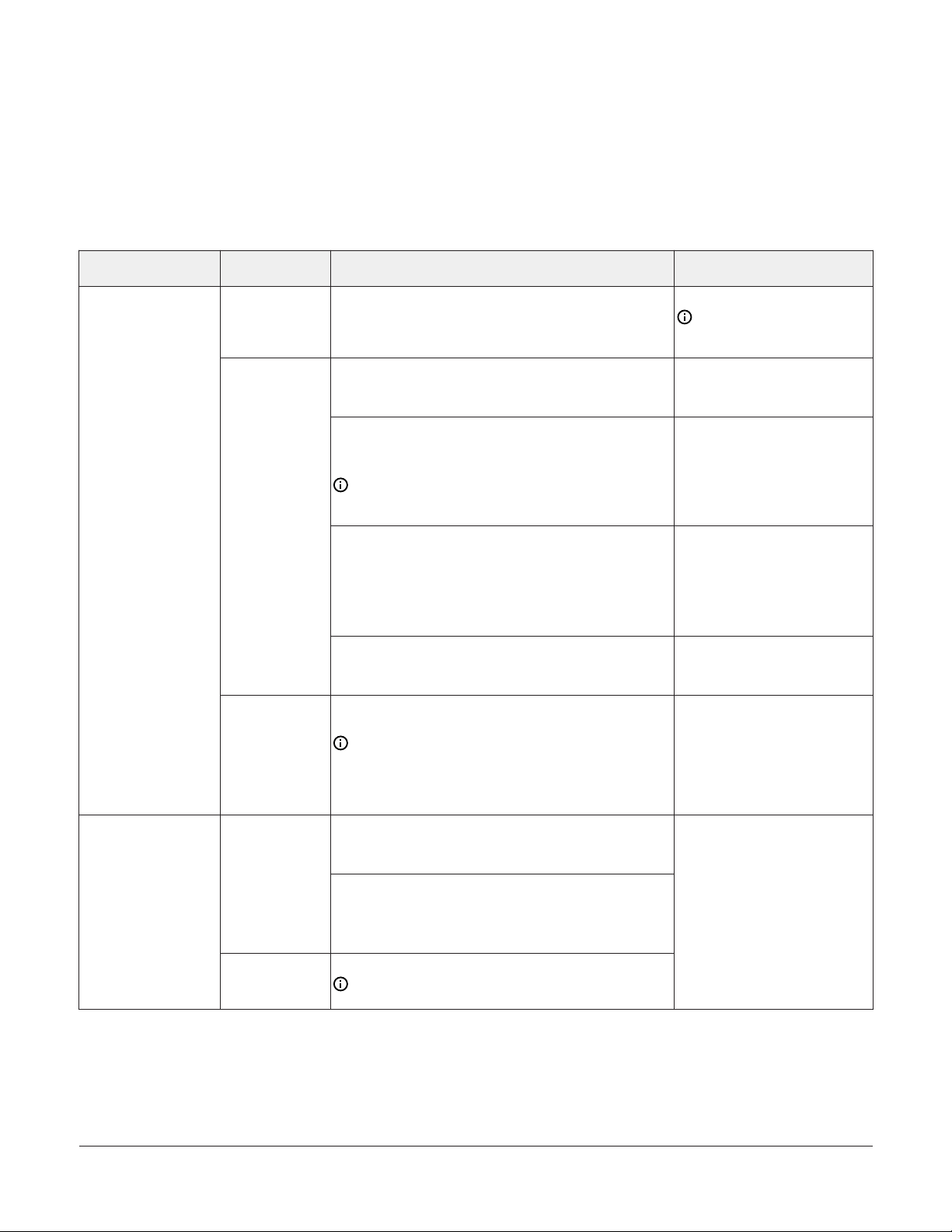
Figure 7: 24 VAC supply power terminal block
wiring
SA Bus port
The Sensor (SA Bus) port on the bottom of the
controller is an RJ-12, 6-position modular jack
that provides a connection for MAP Gateway, the
Bluetooth® Commissioning Converter (BTCVT), the
VAV Balancing Tool, specified network sensors, or
other SA Bus devices with RJ-12 plugs.
A DIS1710 Local Controller Display also can be
connected to the SA Bus port (but only on FEC
models without integral display and push buttons).
The Sensor port is connected internally to the SA
bus terminal block. For more information about the
Sensor port functions, requirements and ratings,
see . The Sensor Port pin assignment is shown in
Figure 6 (but only on FEC models without integral
display and push buttons).
Supply power terminal block
The 24 VAC supply power terminal block is a gray,
removable, 3-terminal plug that fits into a boardmounted jack on the top right of the controller.
Wire the 24 VAC supply power wires from the
transformer to the HOT and COM terminals on the
terminal plug as shown in Figure 7. Do not use the
middle terminal on the supply power terminal block.
See for more information about the Supply Power
Terminal Block.
Note: The supply power wire colors may
be different on transformers from other
manufacturers. Refer to the transformer
manufacturer’s instructions and the project
installation drawings for wiring details.
Important: Connect 24 VAC supply power
to the field controller and all other network
devices so that transformer phasing is uniform
across the network devices. Powering network
devices with uniform 24 VAC supply power
phasing reduces noise, interference, and
ground loop problems. The field controller
does not require an earth ground connection.
Terminal wiring guidelines, functions, ratings, and requirements
Input and Output wiring guidelines
Table 2 provides information and guidelines about
the functions, ratings, and requirements for the
controller input and output terminals. The table also
references guidelines for determining proper wire
sizes and cable lengths.
In addition to the wiring guidelines in Table 2,
observe these guidelines when you wire controller
inputs and outputs:
• Run all low-voltage wiring and cables separate
from high-voltage wiring.
• All input and output cables, regardless of wire
size or number of wires, should consist of
stranded, insulated, and twisted copper wires.
FAC3613 Advanced Application Field Equipment Controller Installation Guide6
Page 7
• Shielded cable is not required for input or output
cables.
• Inputs/outputs with cables less than 30 m (100 ft)
typically do not require an offset in the software
setup. Cable runs over 30 m (100 ft) may require
• Shielded cable is recommended for input
an offset in the input/output software setup.
and output cables that are exposed to high
electromagnetic or radio frequency noise.
I/O Terminal blocks, ratings, and
requirements
Table 2: Terminal blocks, functions, ratings, requirements, and cables
Terminal block label Terminal label Function, ratings, requirements
15 VDC Power Source for active (3-wire) input devices
+15 V
INn
UNIVERSAL
(Inputs)
ICOMn
INn
BINARY
(Inputs)
ICOMn
connected to the Universal INn terminals.
Provides 100 mA total current
Analog Input - Voltage Mode (0–10 VDC)
10 VDC maximum input voltage
Internal 75k ohms pull-down
Analog Input - Current Mode (4–20 mA)
Internal 100 ohms load impedance. See Setting the Input
Jumpers.
Note: A current loop fail-safe jumper must be in
the Enable position to maintain a closed 4 to 20 mA
current loop. See UI current loop jumpers.
Analog Input - Resistive Mode (60–600k ohms)
Internal 12 V. 15k ohms pull-up
Qualified Sensors: 0–2k ohms potentiometer, RTD (1k
Nickel [ Johnson Controls® sensor], 1k Platinum, and
A99B Silicon Temperature Sensor) Negative Temperature
Coefficient (NTC) Sensor
Binary Input - Dry Contact Maintained Mode
1 second minimum pulse width
Internal 12 V. 15k ohms pull-up
Universal Input Common for all Universal Input
terminals
Note: All Universal ICOMn terminals share a
common, which is isolated from all other commons,
except the SA bus common. One common screw
terminal point is provided for every two input screw
terminal points.
Binary Input - Dry Contact Maintained Mode
0.01 second minimum pulse width
Internal 18 V. 3k ohms pull-up
Binary Input - Pulse Counter/Accumulator Mode
0.01 second minimum pulse width
(50 Hz at 50% duty cycle)
Internal 18 V. 3k ohms pull-up
Binary Input Common for all Binary Input (IN) terminals
Note: All Binary ICOMn terminals share a common,
which is isolated from all other commons.
Determine wire size and
maximum cable length
Same as (Universal) INn
Note: Use 3-wire cable for
devices that source power
from the +15V terminal.
See Guideline A in Table 3.
See Guideline B in Table 3.
See Guideline A in Table 3.
See Guideline A in Table 3.
Same as (Universal) INn
See Guideline A in Table 3.
FAC3613 Advanced Application Field Equipment Controller Installation Guide 7
Page 8
Table 2: Terminal blocks, functions, ratings, requirements, and cables
Terminal block label Terminal label Function, ratings, requirements
Analog Output - Voltage Mode (0–10 VDC)
10 VDC maximum output voltage
10 mA maximum output current
Required an external load of 1,000 ohms or more.
Note: The Analog Output (AO) operates in the
Voltage Mode when connected to devices with
impedances greater than 1,000 ohms. Devices that
OUTn
ANALOG
(Outputs)
OCOMn
OUTn
BINARY
(Output)
OCOMn
drop below 1,000 ohm may not operate as intended
for Voltage Mode applications.
Analog Output - Current Mode (4–20 mA)
Requires an external load between 0 and 300 ohms.
Note: The Analog Output (AO) operates in the
Current Mode when connected to devices with
impedances less than 300 ohms. Devices that
exceed below 300 ohms may not operate as
intended for Current Mode applications.
Analog Output Signal Common for all Analog OUT
terminals.
Note: All Analog Output Common terminals
(OCOMn) share a common, which is isolated from
all other commons. One common screw terminal
point is provided for every two output screw
terminal points.
Binary Output - 24 VAC Triac Class 2, 24 V, 500 mA
(External Power Source)
Connects OUTn to OCOMn when activated.
External Power Source Requirements:
30 VAC maximum output voltage
0.5 A maximum output current
1.3 A at 25% duty cycle
40 mA minimum load current
Binary Output Common (for OUTn terminal)
Note: Each Binary Output Common terminal
(OCOMn) is isolated from all other commons,
including other Binary Output Common terminals.
Determine wire size and
maximum cable length
See Guideline C in Table 3.
See Guideline C in Table 3.
Cable and wire length guidelines
The following table defines cable length guidelines
for the various wire sizes that may be used for
wiring low-voltage (<30 V) input and outputs.
Note: The required wire sizes and lengths
for high-voltage (>30 V) Relay Outputs are
determined by the load connected to the relay,
and local, national, or regional electrical codes.
FAC3613 Advanced Application Field Equipment Controller Installation Guide8
Page 9

Table 3: Cable length guidelines for recommended wire sizes for low-voltage (<30 V) Inputs and
Outputs
Wire size/Gauge and type
1.0 mm (18 AWG) stranded copper 457 m (1,500 ft) twisted wire
0.8 mm (20 AWG) stranded copper 297 m (975 ft) twisted wire
A
B
C
0.6 mm (22 AWG) stranded copper 183 m (600 ft) twisted wire
0.5 mm (24 AWG) stranded copper 107 m (350 ft) twisted wire
1.0 mm (18 AWG) stranded copper 229 m (750 ft) twisted wire
0.8 mm (20 AWG) stranded copper 137 m (450 ft) twisted wire
0.6 mm (22 AWG) stranded copper 91 m (300 ft) twisted wire
0.5 mm (24 AWG) stranded copper 61 m (200 ft) twisted wire
See Figure 8 to select wire size/gauge. Use
stranded copper wire
Maximum cable length and
type
See Figure 8 to determine cable
length. Use twisted wire cable.
Assumptions
100 mV maximum voltage drop
Depending on cable and the
connected input or output device, you
may have to define an offset in the
setup software for the input or output
point.
100 mV maximum voltage drop
Depending on cable and the
connected input or output device, you
may have to define an offset in the
setup software for the input or output
point.
N/A
Maximum cable length versus load current
Use Figure 8 to estimate the maximum cable length
relative to the wire size and the load current (in mA)
when wiring inputs and outputs.
Note: Figure 8 applies to low-voltage (<30 V)
inputs and outputs only.
Figure 8: Maximum wire length for low-voltage
(<30 V) Inputs and Outputs by current and wire
size
Communications bus and supply power wiring guidelines
The provides information about the functions,
ratings, and requirements for the communication
bus and supply power terminals. The table also
provides guidelines for wire sizes, cable types, and
cable lengths for when you wire the controller's
communication buses and supply power.
Important: Refer to the N2 Modernization Guide
for Legacy N2 Controllers for guidelines when
using this device on an N2 bus.
In addition, observe these guidelines when you wire
an SA bus and the 24 VAC supply power:
• Run all low-voltage wiring and cables separate
from high-voltage wiring.
• All SA bus cables, regardless of wire size, should
be twisted, insulated, stranded copper wire.
• Shielded cable is strongly recommended for all SA
bus cables.
• Refer to the MS/TP Communications Bus
Technical Bulletin (LIT-12011034) for detailed
information regarding wire size and cable length
requirements for SA buses.
Communications bus and supply power
terminal block
Note: The SA Bus and FC Bus wiring
recommendations in this table are for MS/TP
bus communications at 38.4k baud. For more
information, refer to the MS/TP Communications
Bus Technical Bulletin (LIT-12011034).
FAC3613 Advanced Application Field Equipment Controller Installation Guide 9
Page 10
Table 4: Communications bus and supply power terminal blocks, functions, ratings, requirements, and
cables
Terminal block/
Port label
FC BUS
FC BUS
(Port)
SA BUS
Sensor
(Port)
24~
Terminal labels Function, electrical ratings/Requirements Recommended cable type
+
-
COM
SHLD
+
COM SA Bus Signal Reference and 15 VDC Common
SA PWR
SENSOR
HOT
COM
FC Bus Communications
Signal Reference (Common) for Bus
communications
Isolated terminal (optional shield drain
connection )
RJ-12 6-Position Modular Connector provides:
FC Bus Communications
FC Bus Signal Reference and 15 VDC Common
15 VDC, 180 mA, Power for Bluetooth
Commissioning Converter
SA Bus Communications
15 VDC Supply Power for Devices on the SA Bus
(Maximum total current draw for SA Bus is 240
mA.)
RJ-12 6-Position Modular Connector provides:
SA Bus Communications
SA Bus Signal Reference and 15 VDC Common
15 VDC Power for devices on the SA bus and
Bluetooth Commissioning Converter
24 VAC Power Supply - Hot
Supply 20–30 VAC (Nominal 24 VAC)
24 VAC Power Supply Common (Isolated from
all other Common terminals on controller)
14 VA
0.6 mm (22 AWG) stranded, 3-wire
twisted, shielded cable recommended
Bluetooth Commissioning Converter
retractable cable or 24 AWG 3-pair
CAT 3 cable or above.
0.6 mm (22 AWG) stranded, 4-wire
(2 twisted-pairs), shielded cable
recommended.
Note: The + and - wire are one
twisted pair, and the COM and
SA PWR are the second twisted
pair of wires.
24 AWG 3-pair CAT3 cable <30.5 m
(100 ft)
0.8 mm to 1.0 mm
(18 AWG) 2-wire
FAC3613 Advanced Application Field Equipment Controller Installation Guide10
Page 11

Termination diagrams
A set of Johnson Controls termination diagrams
provides details for wiring inputs and outputs to the
Table 5: Termination details
Type of field
device
Type of Input/
Output
Termination diagrams
controllers. See the figures in this section for the
applicable termination diagrams.
Temperature
Sensor
Voltage Input External Source
Voltage Input Internal Source
UI
UI
UI
Voltage Input
(Self-Powered)
UI
FAC3613 Advanced Application Field Equipment Controller Installation Guide 11
Page 12

Table 5: Termination details
Type of field
device
Current Input External Source
(Isolated)
Current Input Internal Source (2wire)
Type of Input/
Output
UI
UI
Termination diagrams
Current Input Internal Source (3
wire)
Current Input External Source (in
Loop)
Feedback from
EPP-1000
UI
UI
UI
FAC3613 Advanced Application Field Equipment Controller Installation Guide12
Page 13

Table 5: Termination details
Type of field
device
Type of Input/
Output
Termination diagrams
Dry Contact
(Binary Input)
0–10 VDC Output
to Actuator
(External Source)
0–10 VDC Output
to Actuator
(Internal Source)
UI or BI
CO or AO
CO or AO
Current Output CO or AO
24 VAC Triac
Output (Switch
Low, External
Source)
CO or AO
FAC3613 Advanced Application Field Equipment Controller Installation Guide 13
Page 14
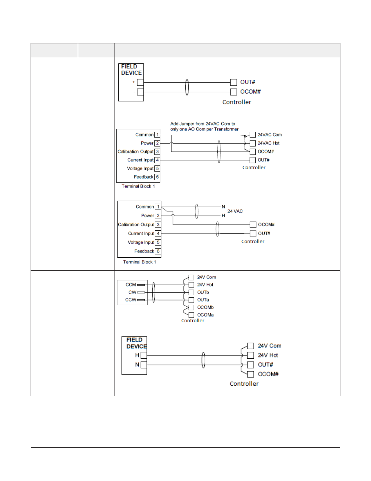
Table 5: Termination details
Type of field
device
Type of Input/
Output
Termination diagrams
Analog Output
(Current)
4–20 mA Output to
Actuator
4–20 mA Output to
Actuator
AO
AO
AO
Incremental
Control to
Actuator (Switch
Low, Externally
Sourced)
24 VAC Binary
Output (Switch
Low, Externally
Sourced)
FAC3613 Advanced Application Field Equipment Controller Installation Guide14
BO
BO
Page 15
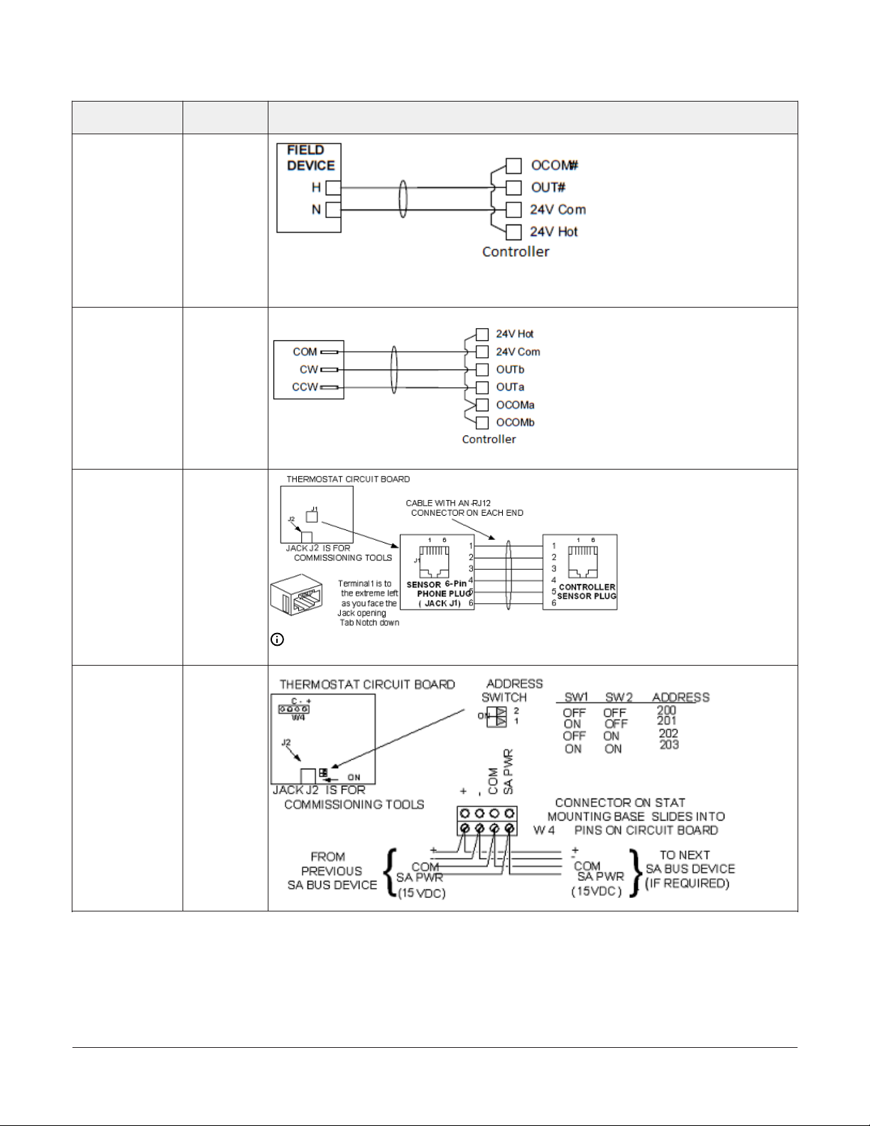
Table 5: Termination details
Type of field
device
24 VAC Binary
Output (Switch
High, Externally
Sourced)
Incremental
Control to
Actuator (Switch
High, Externally
Sourced)
Type of Input/
Output
BO
BO
Termination diagrams
Network Stat with
Phone Jack (Fixed
Address = 199)
Network Stat
with Terminals
Addressable
SA Bus
Note: The bottom jack (J2) on the TE-700 and TE-6x00 Series Sensors is not usable as a zone
bus or an SAB connection.
SA Bus
FAC3613 Advanced Application Field Equipment Controller Installation Guide 15
Page 16

Table 5: Termination details
Type of field
device
Network Stat with
Terminals (Fixed
Address = 199)
Type of Input/
Output
SA Bus
Termination diagrams
Setup and Adjustments
Configuring N2 Communications
N2-capable controllers support the full range of
possible N2 device addresses provided by the N2
protocol standard (1-254).
To configure a controller to communicate using the
N2 protocol, complete the following steps:
1. Disconnect the 24 VAC supply from the
controller.
2. Set the address switches to the desired N2
address. For details about setting a device
address, see Setting the device address.
3. Reconnect the 24 VAC supply to the controller.
4. Using an SA bus connection, download the
firmware and controller application file
configured for N2 to the controller.
Switching the Communications Protocol from N2 to MS/TP
For N2 sites that are converting to BACnet MS/TP,
you can switch the communications protocol of N2configured MS/TP controllers back to BACnet MS/TP.
To switch controller operating in N2 mode back into
BACnet MS/TP mode, complete the following steps:
1. Disconnect the 24 VAC supply from the
controller.
2. Set the address switches to the desired BACnet
MS/TP address. For details about setting a
device address, see Setting the device address.
3. Ensure the DIP switch 128 is set to OFF.
4. Reconnect the 24 VAC supply to the controller.
5. Using an SA Bus connection, download a
controller application file configured for BACnet
MS/TP to the controller.
Configuring Wireless Communications
To configure a controller for use with the ZFR/ZFR
Pro Series Wireless Field Bus system, complete the
following steps:
1. Disconnect the 24 VAC supply from the
controller.
2. Wire the input/output terminals and SA bus.
Note: In wireless network applications, do not
connect any wires to the FC bus terminal block.
(Connect the SA/FC terminal block on an IOM
to an SA bus only.)
3. Important: Before the controller is powered
on, connect the ZFR/ZFR Pro Wireless Field Bus
Router to the FC bus port (RJ-12 modular jack)
on the front of the controller.
FAC3613 Advanced Application Field Equipment Controller Installation Guide16
Page 17

4. Ensure that the controller's device address DIP
switches are set to the correct device address.
For details about setting a device address, see
Setting the device address.
For more information about device addresses in
wireless applications, refer to the WNC1800/ZFR182x
Pro Series Wireless Field Bus System Technical Bulletin
(LIT-12012356) or the ZFR1800 Series Wireless Field
Bus System Technical Bulletin (LIT-12011295).
5. Reconnect the 24 VAC supply to the controller.
Figure 9: Device address DIP switch block set to
address 21
For more information about the ZFR Pro Wireless
Field Bus system, refer to the WNC1800/ZFR182x
Pro Series Wireless Field Bus System Product Bulletin
(LIT-12012320).
For more information about the ZFR 1800 Wireless
Field Bus system, refer to the ZFR1800 Series Wireless
Field Bus System Product Bulletin (LIT-12011336).
Setting the device address
Metasys field controllers are master devices on an
MS/TP (SA or FC) bus. Before you operate field
controllers on a bus, you must set a valid and
unique device address for each controller on the
bus. You set a field controller's device address by
setting the positions of the switches on the DIP
switch block at the top of the controller. Device
addresses 4 through 127 are the valid addresses for
these controllers on an MS/TP FC Bus.
Device Address Use on Description
0
(Switch 128 Off)
1-3
(Switch 128 Off)
4 to 127
(Switch 128 Off)
The DIP switch block has eight switches numbered
128, 64, 32, 16, 8, 4, 2, and 1. Switches 64 through 1
are device address switches. Switch 128 must be set
to OFF for all hard-wired SA and FC bus applications.
Reserved for FC Bus Supervisory
Controller(not for use on field
controllers).
Reserved for peripheral
devices (not for use on field
controllers).
Used for MSTP master devices
(field controllers) that are
hardwired to an SA bus or FC
bus.
Note: Metasys field controllers ship with switch
128 ON and the remainining adress switches
off rendering the controllers wired subordinate
devices, which do not operate on MS/TP
buses, but do not interfere with bus operation.
Set a valid and unique device address on
the controller before applying power to the
controller on the bus.
To set the device addresses on the controllers,
complete the following steps:
1. Set all of the switches on the address DIP
switch block (128 through 1) to OFF.
2. Set one or more of the seven address switches
(64 though 1) to ON, so that the sum of the
switch numbers set to ON equals the intended
device address. Set the highest number switch
that is less than or equal to the intended device
address to ON. Then continue setting lower
numbered switches until the total equals the
intended address. For example, if the intended
device address is 21, set switch 16 to ON first,
then set switch 4 ON, followed by switch 1
(16+4+1= 21). See Figure 9.See for valid device
addresses.
3. Set a unique and sequential device address for
each of the controllers connected on the SA or
FC bus starting with device address 4. To ensure
the best bus performance, set sequential device
addresses with no gaps in the device address
range (4, 5, 6, 7, 8, 9, and so on). The controllers
do not need to be physically connected on the
bus in their numerical device address order.
4. Write each controller's device address on the
white label below the DIP switch block on the
controller's cover.
FAC3613 Advanced Application Field Equipment Controller Installation Guide 17
Page 18

The following table describes the FC bus and SA bus
devices addresses for Johnson Controls® MS/TP
controllers communications bus applications.
Refer to the MS/TP Communications Bus Technical Bul-
letin (LIT-12011034) for more information on controller device addresses and how to set them on
MS/TP buses.
The controller cover is held in place by four
plastic latches that extend from the base and
snap into slots on the inside of the housing
cover.
To remove the controller cover, complete the
following steps:
Removing the Controller cover
Important: Electrostatic discharge can
damage controller components. Use proper
electrostatic discharge precautions during
installation, setup, and servicing to avoid
damaging the controller.
Important: Disconnect all power sources to
the controller before you remove the cover
and change the position of any jumper on the
controller. Failure to disconnect power before
changing a jumper can result in damage to the
controller and void any warranties.
Figure 10: Cover removed showing EOL switch and jumper positions
1. Place your fingertips under the two cover lift
tabs (FAC3613 physical features ) on the sides
of the housing cover and gently pry the top of
the cover away from the base to release the
cover from the two upper latches.
2. Pivot the top of the cover further to release it
from the lower two latches.
3. Replace the cover by placing it squarely over
the base, and then gently and evenly push the
cover on to the latches until they snap into the
latched position.
Setting the End-of-Line (EOL) switch
Each controller has an EOL switch, which, when set
to ON, sets the controller as a terminating device on
the bus. The default EOL switch position is OFF.
FAC3613 Advanced Application Field Equipment Controller Installation Guide18
Figure 11: End-of-Line switch positions
To set the EOL switch on a field controller, complete
the following steps:
1. Determine the physical location of the field
controller on the FC bus.
Page 19

2. Determine if the controller must be set as a
terminating device on the bus.
Note: For detailed information regarding EOL
termination rules and EOL switch settings on
FC buses, refer to the MS/TP Communications
Bus Technical Bulletin (LIT-12011034).
3. If the controller is a terminating device on
the FC bus, set the EOL switch to ON. If the
controller is not a terminating device on the
bus, set the EOL switch to Off.
When a controller is connected to power with its
EOL switch set to ON, the amber EOL LED on the
controller cover is lit.
Setting the Input Jumpers
CAUTION
Risk of Electric Shock:
Disconnect supply power to the controller before attempting to adjust the Binary Output Source Power
Selection Jumpers. Failure to disconnect the supply
power may result in electric shock.
ATTENTION
Risque de décharge électrique
Débrancher l'alimentation de l'controller avant tout
réglage du Binary Output Source Power Selection
Jumpers. Le non-respect de cette précaution risque
de provoquer une décharge électrique.
Figure 12: Current loop jumper positions
Set the current loop jumper to the Enabled position
(Figure 12) to connect an internal 100 ohms resistor
across the UI terminals, which maintains the 4–20
mA current loop circuit even when power to the
controller is interrupted or off.
Important: Current loop jumpers must be in
the Disabled (default) position for all UIs that
are not set up to operate as 4–20 mA analog
inputs.
The following table identifies the current loop
switches associated with each UI on the controller.
Table 6: FAC3613 UI Inputs and jumper labels
Universal Input label Jumper label on circuit board
IN1 J5
IN2 J6
IN3 J7
IN4 J8
IN5 J9
IN6 J10
IN7 J11
IN8 J12
Setting up a local display
UI current loop jumpers
The UI current loop fail-safe jumper pins are located
on the circuit board under the controller cover near
the UI terminals.
FAC3613 Advanced Application Field Equipment Controller Installation Guide 19
The FAC3613 model does not have an integral
display, but you can connect the controller to a
DIS1710 Local Controller Display. For detailed
information about setting up and operating either
an integral user interface or a remotely connected
DIS1710 display, refer to the
Input/Output Wiring Validation
The FAC3613 controllers ship with a default state
that can assist in validating the wiring of the input
and output terminals prior to download of an
application file. When the controller is powered on
in this state, the Fault LED will flash in a pattern of
two quick blinks and then a long pause (see Table 7
).
Page 20

To make use of this feature, ensure the DIP switches
are set to the desired address and wire the input
and output terminals. Apply power to the FAC
controller and connect to the device with either a
MAP Gateway or MS-DIS1710-0 Local Display to view
the points in the controller. The FAC controller will
report an Operational status even though there is
no true application loaded. CCT will not be able to
commission or upload the device as a result until
a true application is downloaded. The application
name displayed will be the address of the controller
followed by the model of the controller and “Default
State”.
For example, a FAC3613 controller whose DIP
switches are set to 8 would have the default state
application name of “8-FAC3613 Default State”.
The default state creates I/O points for all
connections on the input and output terminals.
It assumes all Universal Inputs (UIs) are Nickel
temperature sensors. The default state also takes
input from a Network Sensor at address 199. If there
is no connected Network Sensor, the startup of this
default state will be delayed by 30 seconds as the
controller attempts to establish connection with the
sensor.
software licensing portal, and are loaded and
licensed on the computer/server that is running
CCT.
For additional information about the firmware
package files, refer to the CCT Installation Instructions
(LIT-12011259).
Troubleshooting Controllers
Observe the Status LEDs on the front of the field
controller and see the table below to troubleshoot
the controller. To troubleshoot an integral or
local controller display, refer to the DIS1710 Local
Controller Display Technical Bulletin (LIT-12011270).
Commissioning Controllers
You commission BACnet MS/TP controllers with the
(Controller Configuration Tool ) CCT software. The
controller can be connected using NxE Passthru,
Bluetooth (using BTCVT), or through MAP 4.2+/
BACnet Router (Mobile Access Portal (MAP) Gateway
at version 4.2 or above). Refer to Controller Tool
Help (LIT-12011147) for detailed information on
commissioning field controllers. Beginning at
CCT Release 13, the firmware package files are
orderable separately; they are not included with
CCT. They are obtained from the Metasys software
licensing portal, and are loaded and licensed on the
computer/server that is running CCT. .
Note: The MAP Gateway serves as a
replacement for the BTCVT, which is no longer
available for purchase, but continues to be
supported.
Firmware Package File
The MS-FCP-0 equipment controller firmware
package files are required for CCT to configure and
commission the controllers. The firmware package
files also allow you to upgrade an existing controller
to the latest firmware release available for that
controller.
Beginning at CCT Release 13, the firmware package
files are orderable separately; they are not included
with CCT. They are obtained from the Metasys
FAC3613 Advanced Application Field Equipment Controller Installation Guide20
Page 21

LED status and states
Table 7: Status LEDs and description of LED states
LED label LED color Normal LED state Description of LED states
Off Steady = No Supply Power or the controller’s polyswitch/resettable fuse is
POWER Green On Steady
FAULT Red Off Steady
SA BUS Green Blink - 2 Hz
FC BUS Green Blink - 2 Hz
Off (Except on
EOL Amber
terminating
devices)
open. Check Output wiring for short circuits and cycle power to controller.
On Steady = Power Connected
2 blinks followed by long pause = Controller powered on in default state. For more
information about this default state, see Input/Output Wiring Validation.
Off Steady = No Faults
On Steady = Device Fault; no application loaded; Main Code download required,
if controller is in Boot mode or a firmware mismatch exists between the and the
ZFR1811 Wireless Field Bus Router..
Blink - 2 Hz = Download or Startup in progress, not ready for normal operation
Blink - 2 Hz = Data Transmission (normal communication)
Off Steady = No Data Transmission (N/A - auto baud not supported)
On Steady = Communication lost, waiting to join communication ring
Blink - 2 Hz = Data Transmission (normal communication)
Off Steady = No Data Transmission (auto baud in progress)
On Steady = Communication lost, waiting to join communication ring
On Steady = EOL switch in ON position
Off Steady = EOL switch in Off position
Repair information
If controller fails to operate within its specifications,
replace the controller. For a replacement controller,
contact your Johnson Controls representative.
FAC3613 Advanced Application Field Equipment Controller Installation Guide 21
Page 22

Accessories ordering information
Table 8: Accessories Ordering Information
Product Code Number Description
IOM Series Controllers
Mobile Access Portal
(MAP) Gateway
TL-CCT-0 Metasys Controller Configuration Tool (CCT) Software
MS-FCP-0 Metasys Equipment Controller Firmware Package Files for CCT
MS-DIS1710-0 Local Controller Display
NS Series Network
Sensors
TP-2420 Transformer, 120 VAC Primary to 24 VAC secondary, 20 VA, Wall Plug
Y65T31-0
AS-XFR050-0
AS-CBLTSTAT-0 Cable adapter for connecting to 8-pin TE-6700 Series sensors
AP-TBK4SA-0 Replacement SA Bus Terminal Blocks, 4-Position, Brown, Bulk Pack of 10
AP-TBK4FC-0 Replacement FC Bus Terminal Blocks, 4-Position, Blue, Bulk Pack of 10
AP-TBK3PW-0 Replacement Power Terminal Blocks, 3-Position, Gray, Bulk Pack of 10
WNC1800/ZFR182x
Pro Wireless field Bus
System
ZFR1800 Series Wireless
Field Bus System
WRZ Series Wireless
Room Sensors
Refer to the Metasys® System Field Equipment Controllers and Related Products Product Bulletin (LIT-12011042)
for a complete list of available IOM Series Controllers.
Refer to the Mobile Access Portal Gateway Catalog Page (LIT-1900869) to identify the appropriate product for
your region.
Note: The MAP Gateway serves as a replacement for the BTCVT, which is no longer available for
purchase, but continues to be supported.
Refer to the NS Series Network Sensors Product Bulletin (LIT-12011574) for specific sensor model descriptions.
Transformer, 120/208/240 VAC Primary to 24 VAC Secondary, 40 VA, Foot Mount, 8 in. Primary Leads and
Secondary Screw Terminals, Class 2
Note: Additional Y6x-x Series transformers are also available. Refer to the Series Y63, Y64, Y65, Y66, and
Y69 Transformers Product Bulletin (LIT-125755)
for more information.Power transformer (Class 2, 24 VAC, 50 VA maximum output), no enclosure for more
information.
This system is used for installations that support BACnet/IP but can also coexist with the ZFR1800 Series
when installed under the same supervisor (i.e., network engine). Refer to the WNC1800/ZFR182x Pro Series
Wireless Field Bus System Product Bulletin (LIT-12012320) for a list of available products.
This system is used for installations that only support BACnet MS/TP. Refer to the ZFR1800 Series Wireless Field
Bus System Product Bulletin (LIT-12011336) for a list of available products.
Refer to the WRZ Series Wireless Room Sensors Product Bulletin (LIT-12000653) for specific sensor model
descriptions.
FAC3613 Advanced Application Field Equipment Controller Installation Guide22
Page 23

Technical specifications
Table 9: FAC3613 Advanced Application Field Equipment Controller
Product Code Numbers MS-FAC3613-0 Advanced Application Field Equipment Controller with Fast Persistence
Power Requirement
Power Consumption
Power Source
Ambient Conditions
Controller Addressing for BACnet MS/TP
Controller Addressing for N2 DIP switch set; valid control device addresses 1-254
Communications Bus
Processor RX631 32-Bit Renesas® microcontroller
Memory 16 MB flash memory and 8 MB RAM
Real-Time Clock Backup Power Supply
Input and Output Capabilities
Analog Input/Analog Output Resolution
and Accuracy
Terminations
Mounting
Housing
Dimensions (Height x Width x Depth)
Weight 0.5 kg (1.1 lb)
24 VAC (nominal, 20 VAC minimum/30 VAC maximum), 50/60 Hz, power supply Class 2
(North America), Safety Extra-Low Voltage (SELV) (Europe)
14 VA maximum
Note: The VA rating does not include any power supplied to the peripheral devices
connected to binary outputs (BOs) or configurable outputs (COs), which can
consume up to 12 VA for each BO or CO; for a possible total consumption of an
additional 72 VA (maximum).
+15 VDC power source terminals provide 100 mA total current. Quantity 2 located in
Universal IN terminals - for active (3-wire) input devices
Operating: 0°C to 50°C (32°F to 122°F); 10% to 90% RH noncondensing
Storage: -40°C to 80°C (-40°F to 176°F); 5% to 95% RH noncondensing
DIP switch set; valid controller device addresses 4–127 (Device addresses 0–3 and 128–255
are reserved and not valid controller addresses.)
Selectable N2 or BACnet® MS/TP, RS-485:
3-wire FC Bus between the supervisory controller and field controllers
4-wire SA Bus between field controller, network sensors and other sensor/actuator
devices, includes a lead to source 15 VDC supply power (from field controller) to bus
devices.
Super capacitor maintains power to the onboard real-time clock for a minimum of 72
hours when supply power to the controller is disconnected.
8 - Universal Inputs: Defined as 0–10 VDC, 4–20 mA, 0–600k ohms, or Binary Dry Contact
6 - Binary Inputs: Defined as Dry Contact Maintained or Pulse Counter/Accumulator
Mode
6 - Binary Outputs: Defined as 24 VAC Triac (external power source only)
6 - Analog Outputs: Defined as 0–10 VDC or 4–20 mA
Input: 15-bit resolution
Output: 15-bit resolution, +/- 200 mV accuracy in 0–10 VDC applications
Input/Output: Fixed Screw Terminal Blocks
SA/FC Bus and Supply Power: 4-Wire and 3-Wire Pluggable Screw Terminal Blocks
SA/FC Bus Port: RJ-12 6-Pin Modular Jacks
Horizontal on single 35 mm DIN rail mount (preferred), or screw mount on flat surface
with three integral mounting clips on controller
Enclosure material: ABS and polycarbonate UL94 5VB; Self-extinguishing
Protection Class: IP20 (IEC529)
150 mm x 220 mm x 57.5 mm (5-7/8 in. x 8-3/4 in. x 2-3/8 in.) including terminals and
mounting clips
Note: Mounting space requires an additional 50 mm (2 in.) space on top,
bottom, and front face of controller for easy cover removal, ventilation, and wire
terminations.
FAC3613 Advanced Application Field Equipment Controller Installation Guide 23
Page 24

Table 9: FAC3613 Advanced Application Field Equipment Controller
Compliance
United States: UL Listed, File E107041, CCN PAZX, UL 916, Energy Management
Equipment
FCC Compliant to CFR47, Part 15, Subpart B, Class A
Canada: UL Listed, File E107041, CCN PAZX7 CAN/CSA C22.2 No. 205, Signal Equipment
Industry Canada Compliant, ICES-003
Europe: Johnson Controls declares that this product is in compliance with the essential
requirements and other relevant provisions of the EMC Directive.
Australia and New Zealand: RCM Mark, Australia/NZ Emissions Compliant
BACnet International: BACnet Testing Laboratories™ (BTL) Protocol Revision 15 Listed
and Certified BACnet Advanced Application Controller (B-AAC), based on the ANSI/ASHRAE
135-2016
The performance specifications are nominal and
conform to acceptable industry standard. For
application at conditions beyond these specifications,
consult the local Johnson Controls office. Johnson
Controls shall not be liable for damages resulting from
misapplication or misuse of its products.
Product warranty
This product is covered by a limited
warranty, details of which can be found at
www.johnsoncontrols.com/buildingswarranty.
Single point of contact
APAC Europe NA/SA
JOHNSON CONTROLS
C/O CONTROLS PRODUCT
MANAGEMENT
NO. 32 CHANGJIJANG RD NEW
DISTRICT
WUXI JIANGSU PROVINCE 214028
CHINA
For more contact information, refer to
www.johnsoncontrols.com/locations.
JOHNSON CONTROLS
WESTENDHOF 3
45143 ESSEN
GERMANY
JOHNSON CONTROLS
507 E MICHIGAN ST
MILWAUKEE WI 53202
USA
© 2019 Johnson Controls. All rights reserved. All specifications and other information shown were current as of document revision and
are subject to change without notice.
www.johnsoncontrols.com
 Loading...