

Page 1

FAC2612-1 Advanced Application Field
Equipment Controller Installation Guide
Application
The FAC2612-1 Advanced Application Field
Equipment Controller (FAC) is part of the Metasys®
system Field Equipment Controller family. The FAC26
Series controllers run pre-engineered and userprogrammed applications and provide the inputs
and outputs required to monitor and control a wide
variety of HVAC equipment.
FAC26 field controllers operate on an RS-485
BACnet® MS/TP Bus as BACnet Advanced
Application Controllers (B-AACs) integrate into
Johnson Controls® and third-party BACnet systems.
FAC26 controllers include an integral real-time clock,
which enables the controllers to monitor and control
schedules, calendars, and trends, and operate for
extended periods of time as stand-alone controllers
when offline from the system network.
Switchable communications protocols
By default, the Metasys system FEC Family
Controllers and network sensors communicate using
the standard BACnet protocol based on the ANSI/
ASHRAE 135-2008. The BACnet protocol is a standard
for ANSI, ASHRAE, and the International Standards
Organization (ISO) for building controls.
FEC, VMA16, and VMA18 are BTL-listed as BACnet
Application Specific Controllers (B-ASCs). FAC Field
Controllers and the VMA1930 Field Controller
are BTL-listed as BACnet Advanced Application
Controllers (B-AACs). The NS Series Sensors are BTLlisted as BACnet Smart Sensors (B-SSs).
Release 10.1 and later of the Controller
Configuration Tool (CCT) can be used to switch the
Field Bus communications protocol in supported FEC
Family Field Controllers to be either the standard
BACnet MS/TP or the N2 protocol. All new controllers
use BACnet MS/TP as the default communications
protocol. Switchable communications protocols in
the MS/TP models provide a cost-effective upgrade
and modernization path for customers with existing
N2 controllers.
Part No. 24-10143-195 Rev. L
2019-10-18
The N2-capable FEC Family Controllers can be used
as functional replacements for legacy N2 controllers.
The N2-capable FEC Family Controllers:
• have the input and output (I/O) quantities and
characteristics of the FEC Family Controllers
• must be programmed with CCT
• support SA Bus devices
• support WRZ wireless sensors from the controller
using the WRZ-7860 receiver (most models)
• are available in Buy American versions (most
models)
• are listed for UL 864 UUKL/ORD-C100-13 UUKLC
10th Edition Smoke Control (some models). N2 is
now supported as part of the Metasys 10th Edition
listing for Smoke Control System Equipment. For
details, refer to the Metasys System UL 864 10th
Edition UUKL/ORD-C100-13 UUKLC Smoke Control
System Technical Bulletin (LIT-12012487).
The N2-capable controllers:
• do not support Zone Bus (for example, TMZ
sensors and M100 actuators) or XT-Bus (System
91) devices (for example, XT, XTM, and XP
modules)
• do not support a wireless connection to the N2
bus
• do not support NxE passthrough
North American emissions compliance
United States
This equipment has been tested and found to
comply with the limits for a Class A digital device
pursuant to Part 15 of the FCC Rules. These limits
are designed to provide reasonable protection
against harmful interference when this equipment
is operated in a commercial environment. This
equipment generates, uses, and can radiate radio
frequency energy and, if not installed and used in
accordance with the instruction manual, may cause
harmful interference to radio communications.
Operation of this equipment in a residential area
*2410143195L*
(barcode for factory use only)
MS-FAC2612-1
Page 2

may cause harmful interference, in which case the
users will be required to correct the interference at
their own expense.
Canada
This Class (A) digital apparatus meets all the
requirements of the Canadian Interference-Causing
Equipment Regulations.
Cet appareil numérique de la Classe (A) respecte
toutes les exigences du Règlement sur le matériel
brouilleur du Canada.
Installation
Observe these guidelines when installing a field
controller
• Transport the controller in the original container
to minimize vibration and shock damage.
• Verify that all parts shipped with the controller.
• Do not drop the controller or subject it to physical
shock.
Parts included
• One field controller with removable terminal
blocks
• One installation instructions sheet
Materials and special tools needed
• Three fasteners appropriate for the mounting
surface (M4 screws or #8 screws)
• One 20 cm (8 in.) or longer piece of 35 mm DIN
rail and appropriate hardware for DIN rail mount
(only)
• Small straight-blade screwdriver for securing
wires in the terminal blocks
FAC2612-1 Advanced Application Field Equipment Controller Installation Guide2
Page 3
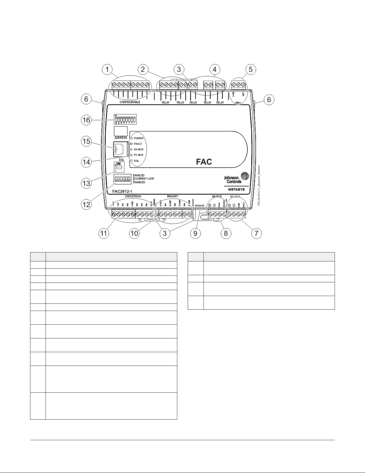
FAC2612-1 physical features
Figure 1: FAC2612-1 physical features
Table 1: FAC2612-1 physical features
Physical feature: description and references
1 Configurable Output (COs) Terminal Blocks. See Table 2.
2 SPDT Relay Terminal Blocks. See Table 2.
3 Mounting Clips. See Figure 3.
4 SPST Relay Terminal Blocks. See Table 2.
24 VAC, Class 2 Supply Power Terminal Block. See Supply
5
power terminal block.
6 Cover Lift Tab
Field Controller (FC) Bus Terminal Block. See FC bus
7
terminal block.
Sensor Actuator (SA) Bus Terminal Block. See SA bus
8
terminal block.
Sensor Actuator (SA) Bus Port (RJ-12 6-pin Modular Jack).
9
See SA Bus port.
Binary Input (BI) Terminal Blocks. Dry Contact Maintained
10
or Pulse Counter/Accumulator Mode. See Table 2.
Universal Inputs (UI) Terminal Blocks. Can be defined as
Voltage Analog Input (0–10 VDC), Current Analog Input
11
(4–20 mA), Resistive Analog Inputs (0–600k ohm), or Dry
Contact Binary Input. See Table 2.
Current Loop Mode DIP Switch Block for Universal Inputs
that are defined as Current Analog Input (4–20 mA) in
12
the system software. See Setting the UI current loop DIP
switches.
Table 1: FAC2612-1 physical features
Physical feature: description and references
End-of-Line (EOL) Switch. See Setting the End-of-Line
13
(EOL) switch.
14 LED Status Indicators. See Table 8.
Field Controller (FC) Bus Port (RJ-12 6-pin Modular Jack).
15
See FC bus port.
Device Address DIP Switch Block. See Setting the device
16
addresses.
Mounting
Observe these guidelines when mounting a field
controller:
• Ensure the mounting surface can support the
controller, DIN rail, and any user-supplied
enclosure.
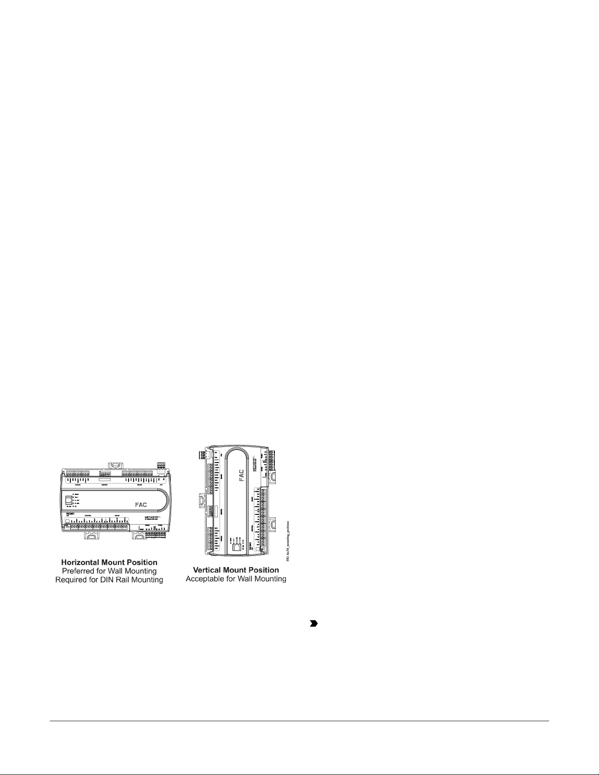
• Mount the controller horizontally on 35 mm DIN
rail whenever possible.
• Mount the controller in the proper mounting
position (Figure 2).
• Mount the controller on a hard, even surface
whenever possible in wall-mount applications.
FAC2612-1 Advanced Application Field Equipment Controller Installation Guide 3
Page 4
• Use shims or washers to mount the controller
securely and evenly on the mounting surface.
• Mount the controller in an area free of corrosive
vapors and observe the Ambient Conditions
requirements in Table 10.
• Provide for sufficient space around the controller
for cable and wire connections for easy cover
removal and good ventilation through the
controller (50 mm [2 in.] minimum on the top,
bottom, and front of the controller).
• Do not mount the controller on surfaces prone to
vibration, such as duct work.
• Do not mount the controller in areas where
electromagnetic emissions from other
devices or wiring can interfere with controller
communication.
Observe these additional guidelines when mounting
a field controller in a panel or enclosure:
• Mount the controller so that the enclosure walls
do not obstruct cover removal or ventilation
through the controller.
• Mount the controller so that the power
transformer and other devices do not radiate
excessive heat to the controller.
• Do not install the controller in an airtight
enclosure.
1. Securely mount a 20 cm (8 in.) or longer section
of 35 mm DIN rail horizontal and centered in
the desired space so that the controller mounts
in the horizontal position shown in Figure 2.
2. Pull the two bottom mounting clips outward
from the controller to the extended position
(Figure 3).
3. Hang the controller on the DIN rail by the hooks
at the top of the (DIN rail) channel on the back
of the controller (Figure 3), and position the
controller snugly against the DIN rail.
4. Push the bottom mounting clips inward (up) to
secure the controller on the DIN rail.
To remove the controller from the DIN rail, pull the
bottom mounting clips out to the extended position
and carefully lift the controller off the DIN rail.
Wall mount applications
To mount a field controller directly on a wall or
other flat vertical surface:
1. Pull the two bottom mounting clips outward
and ensure they are locked in the extended
position as shown in Figure 3.
Figure 2: Field Controller mounting positions
DIN rail mount applications
Mounting the field controller horizontal on 35 mm
DIN rail is the preferred mounting method.
To mount a field controller on 35 mm DIN rail:
2. Mark the mounting hole locations on the wall
using the dimensions in Figure 3 and one of the
mount positions shown in Figure 2. Or hold the
controller up to the wall or surface in a proper
mount position and mark the hole locations
through the mounting clips.
3. Drill holes in the wall or surface at the marked
locations, and insert appropriate wall anchors
in the holes (if necessary).
4. Hold the controller in place, and insert the
screws through the mounting clips and into the
holes (or anchors). Carefully tighten all of the
screws.
Important: Do not overtighten the mounting
screws. Overtightening the screws may
damage the mounting clips.
FAC2612-1 Advanced Application Field Equipment Controller Installation Guide4
Page 5
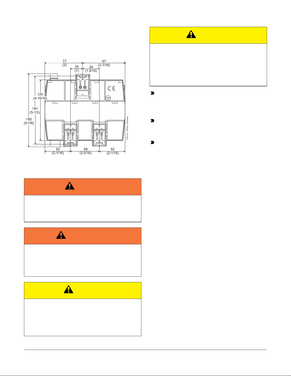
Mounting features and dimensions
Figure 3: Back of Controller showing extended
mounting clips, DIN rail channel, and mounting
dimensions, mm (in.)
Wiring
Warning
ATTENTION
Risque de dégâts matériels
Ne pas mettre le système sous tension avant d'avoir
vérifié tous les raccords de câblage. Des fils formant un court-circuit ou connectés de façon incorrecte risquent d'endommager irrémédiablement
l'équipement.
Important: Do not exceed the controller
electrical ratings. Exceeding controller electrical
ratings can result in permanent damage to the
controller and void any warranty.
Important: Use copper conductors only. Make
all wiring in accordance with local, national, and
regional regulations.
Important: Electrostatic discharge can
damage controller components. Use proper
electrostatic discharge precautions during
installation, setup, and servicing to avoid
damaging the controller.
For detailed information on configuring and
wiring an MS/TP Bus, FC bus, and SA bus, refer to
the MS/TP Communications Bus Technical Bulletin
(LIT-12011034).
Risk of Electric Shock
Disconnect the power supply before making electrical
connections to avoid electric shock
Avertissement
Risque de décharge électrique
Débrancher l'alimentation avant de réaliser tout raccordement électrique afin d'éviter tout risque de
décharge électrique.
CAUTION
Risk of Property Damage
Do not apply power to the system before checking all
wiring connections. Short circuited or improperly connected wires may result in permanent damage to the
equipment.
FAC terminal blocks and bus ports
See FAC2612-1 physical features for terminal block
and bus port locations on the FAC2612-1 controller.
Observe the following guidelines when wiring a
controller.
Input and Output terminal blocks
On most field controller models, all of the input
terminal blocks are mounted on the bottom of
the controller and the output terminal blocks are
mounted on the top of the controller. See Table 2
for more information about I/O terminal functions,
requirements, and ratings.
FC bus terminal block
The FC Bus terminal block is a blue, removable, 4terminal plug that fits into a board-mounted jack.
Wire the removable FC bus terminal block plugs on
the controller, and other controllers in a daisy-chain
configuration using 3-wire twisted, shielded cable as
shown in Figure 4. See Table 4 for more information.
FAC2612-1 Advanced Application Field Equipment Controller Installation Guide 5
Page 6
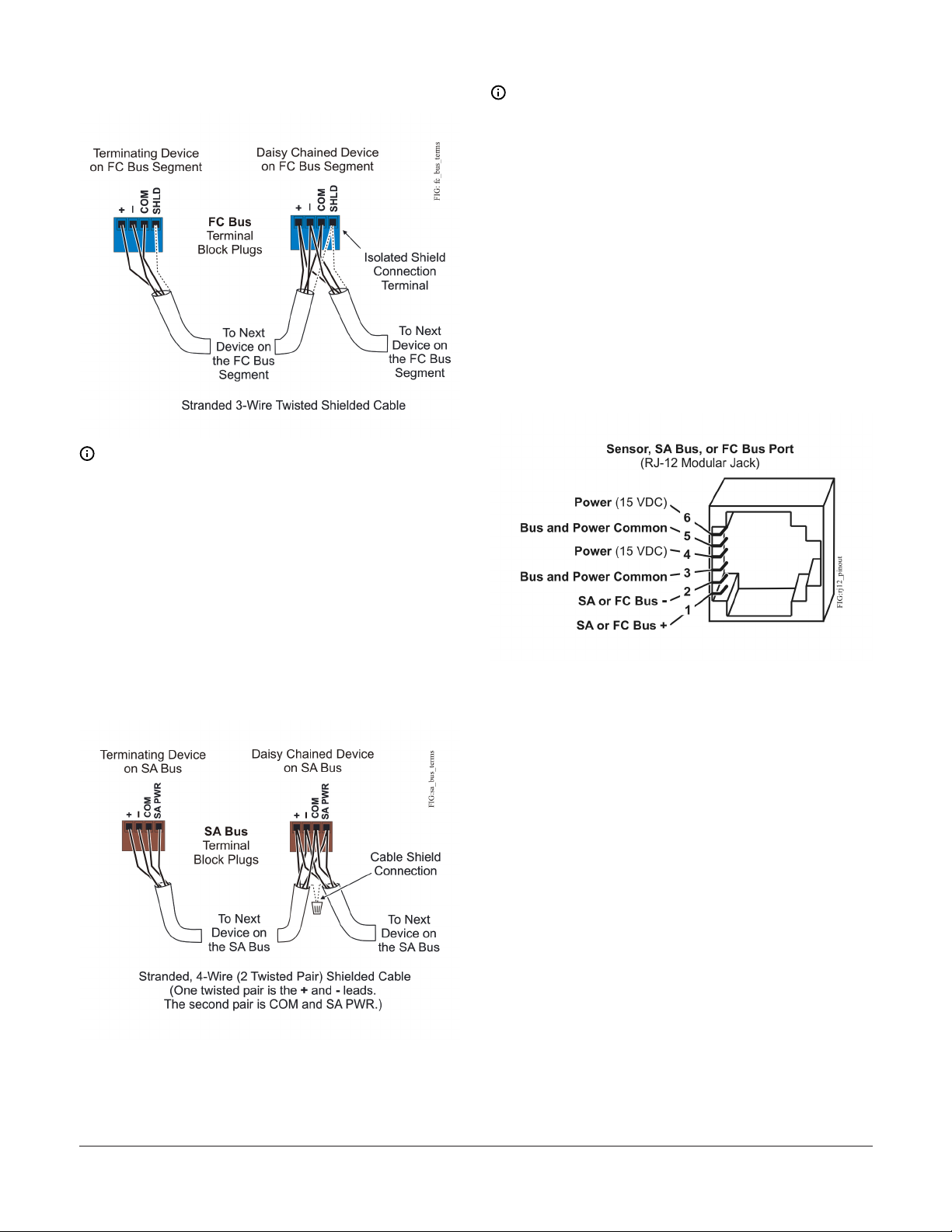
Figure 4: FC bus terminal block wiring
Note: The FC bus Shield (SHLD) terminal is
isolated and can be used to connect (daisy
chain) the shields for FC bus wiring.
SA bus terminal block
Note: The SA PWR terminal supplies 15 VDC.
The SA PWR terminal can be used to connect
(daisy chain) the 15 VDC power leads on the SA
bus.
FC bus port
The FC bus port on the front of the controller is
an RJ-12, 6-position modular jack that provides a
connection for the Bluetooth® Commissioning
Converter, or a ZFR/ZFR Pro Wireless Field Bus
Router.
The FC bus port is connected internally to the FC bus
terminal block. See Table 4 for more information.
The FC bus port pin assignment is shown in Figure .
Figure 6: Pin number assignments for sensor, SA
bus, and FC bus ports on Controllers
The SA Bus terminal block is a brown, removable, 4terminal plug that fits into a board-mounted jack.
Wire the removable SA Bus terminal block plugs on
the controller, and other SA bus devices in a daisychain configuration using 4-wire twisted, shielded
cable as shown in Figure 5. See Table 4 for more
information.
Figure 5: SA bus terminal block wiring
SA Bus port
The Sensor (SA Bus) port on the bottom of the
controller (Figure 1) is an RJ-12, 6-position modular
jack that provides a connection for the Bluetooth
Commissioning Converter, the VAV Balancing Tool,
specified network sensors, or other SA Bus devices
with RJ-12 plugs.
A DIS1710 Local Controller Display also can be
connected to the SA Bus port.
The Sensor port is connected internally to the
SA bus terminal block. See Table 4 for more
information. The Sensor Port pin assignment is
shown in Figure 6.
Supply power terminal block
The 24 VAC supply power terminal block is a gray,
removable, 3-terminal plug that fits into a boardmounted jack on the top right of the controller.
Wire the 24 VAC supply power wires from the
transformer to the HOT and COM terminals on
the terminal plug as shown in Figure . The middle
terminal on the supply power terminal block is not
FAC2612-1 Advanced Application Field Equipment Controller Installation Guide6
Page 7
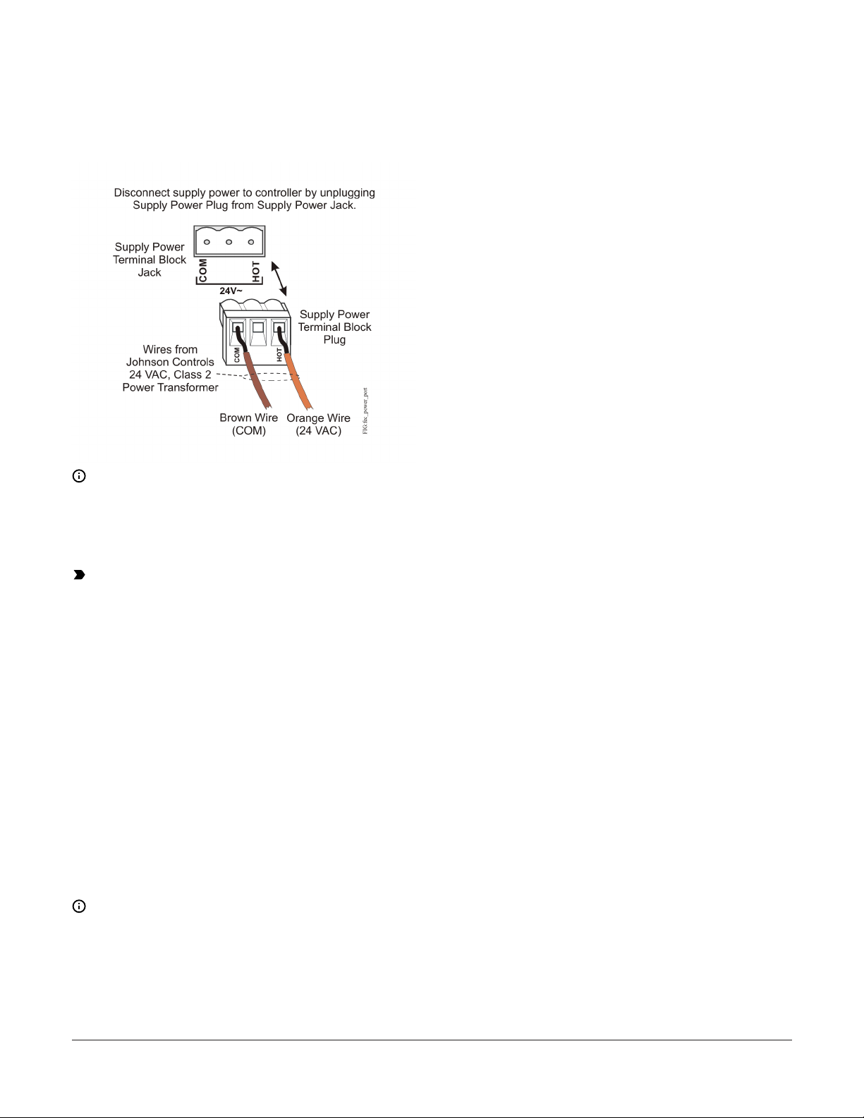
used. See Table 4 for more information about the
Supply Terminal Block.
Figure 7: 24 VAC supply power terminal block
wiring
2. Connect the ZFR/ZFR Pro Wireless Field Bus
Router to the FC bus port (RJ-12 modular jack)
on the front of the controller.
3. Ensure that the controller's device address DIP
switches are set to the correct device address.
See Setting the device addresses.
4. Set DIP switch 128 to ON, which enables
wireless operation on the controller.
For more information on the ZFR Pro Wireless
Field Bus system, refer to the WNC1800/ZFR182x
Pro Series Wireless Field Bus System Product Bulletin
(LIT-12012320).
For more information on the ZFR 1800 Wireless Field
Bus system, refer to the ZFR1800 Series Wireless Field
Bus System Product Bulletin (LIT-12011336).
Terminal Wiring Guidelines,
Functions, Ratings, and
Note: The supply power wire colors may
be different on transformers from other
manufacturers. Refer to the transformer
manufacturer’s instructions and the project
installation drawings for wiring details.
Important: Connect 24 VAC supply power
to the field controller and all other network
devices so that transformer phasing is uniform
across the network devices. Powering network
devices with uniform 24 VAC supply power
phasing reduces noise, interference, and
ground loop problems. The field controller
does not require an earth ground connection.
Wireless network applications
When configured for BACNet MS/TP
communication, the controller can also be installed
in a wireless application using a ZFR/ZFR Pro
Wireless Field Bus Router.
To configure a controller for use with the ZFR/ZFR
Pro Series Wireless Field Bus system:
1. Wire the input/output terminals and SA bus.
Requirements
Input and Output wiring guidelines
Table 2 provides information and guidelines
about the functions, ratings, and requirements
for the controller input and output terminals; and
references guidelines for determining proper wire
sizes and cable lengths.
In addition to the wiring guidelines in Table 2,
observe these guidelines when wiring controller
inputs and outputs:
• Run all low-voltage wiring and cables separate
from high-voltage wiring.
• All input and output cables, regardless of wire
size or number of wires, should consist of
stranded, insulated, and twisted copper wires.
• Shielded cable is not required for input or output
cables.
• Shielded cable is recommended for input
and output cables that are exposed to high
electromagnetic or radio frequency noise.
Note: In wireless network applications, do not
connect any wires to the FC bus terminal block.
(Connect the SA/FC terminal block on an IOM
to an SA bus only).
FAC2612-1 Advanced Application Field Equipment Controller Installation Guide 7
• Inputs/outputs with cables less than 30 m (100 ft)
typically do not require an offset in the software
setup. Cable runs over 30 m (100 ft) may require
an offset in the input/output software setup.
Page 8
FAC2612-1 I/O wiring ratings and requirements table
Table 2: Field Controller terminal blocks, functions, ratings, requirements, and cables
Terminal block label
UNIVERSAL
(Inputs)
BINARY
(Inputs)
Terminal
label
+15 V
+5 V
INn
ICOMn
INn
ICOMn
Function, ratings, requirements
15 VDC Power Source for active (3-wire) input devices
connected to the Universal INn terminals.
Provides 100 mA total current
5 VDC Power Source for active (3-wire) input devices
connected to the Universal INn terminals.
Provides 40 mA total current.
Analog Input - Voltage Mode (0–10 VDC)
10 VDC maximum input voltage
Internal 75k ohm Pull-down
Analog Input - Current Mode (4–20 mA)
Internal 100 ohm load impedance
Note: A current loop fail-safe jumper can be positioned
to maintain a closed 4 to 20 mA current loop, even when
the power to the controller is interrupted or off. See
Setting the UI current loop DIP switches.
Analog Input - Resistive Mode (0–600k ohm)
Internal 12 V. 15k ohm pull up
Qualified Sensors: 0–2k ohm potentiometer
RTD (1k Nickel [ Johnson Controls sensor] 1k Platinum, and
A99B Silicon Temperature Sensor)
Negative Temperature Coefficient (NTC) Sensor (10k Type L,
10k JCI Type II, 2.252k Type II)
Binary Input - Dry Contact Maintained Mode
1 second minimum pulse width
Internal 12 V. 15k ohm pull up
Universal Input Common for all Universal Input terminals
Note: All Universal ICOMn terminals share a common,
which is isolated from all other commons.
Binary Input - Dry Contact Maintained Mode
0.01 second minimum pulse width
Internal 18 V 3k ohm pull up
Binary Input - Pulse Counter/Accumulator Mode
0.01 second minimum pulse width
(50 Hz at 50% duty cycle)
Internal 18 V 3k ohm pull up
Binary Input Common for all Binary Input (IN) terminals
Note: All Binary ICOMn terminals share a common,
which is isolated from all other commons, except the
Configurable Output (CO) common (OCOMn) when the
CO is defined as an Analog Output.
Determine wire size and
maximum cable length
Same as (Universal) INn
Note: Use 3-wire cable for
devices that source power
from the +15V terminal.
Same as (Universal) INn.
Note: Use 3-wire cable for
devices that source power
from the +5 V terminal.
See Guideline A in Table 3.
See Guideline B in Table 3.
See Guideline A in Table 3.
See Guideline A in Table 3.
Same as (Universal) INn
See Guideline A in Table 3.
FAC2612-1 Advanced Application Field Equipment Controller Installation Guide8
Page 9

Table 2: Field Controller terminal blocks, functions, ratings, requirements, and cables
Terminal block label
CONFIGURABLE
(Outputs)
RELAY
(Outputs)
Terminal
label
OUTn
OCOMn
OUT NOn
OCOMn
OUT NCn
Function, ratings, requirements
Analog Output - Voltage Mode (0–10 VDC)
10 VDC maximum output voltage
10 mA maximum output current
Required an external load of 1,000 ohm or more.
Binary Output - 24 VAC Triac (External Power Source only)
Connects OUTn to OCOMn when activated.
External Power Source Requirements:
30 VAC maximum output voltage
0.5 A maximum output current
1.3 A at 25% duty cycle
40 mA minimum load current
Analog Output Signal Common All Configurable Outputs
(COs) defined as Analog Outputs (AOs) share a common,
which is isolated from all other commons except the Binary
Input common.
Binary Output Signal Common All Configurable Outputs
(COs) defined as Binary Outputs are isolated from all other
commons, including other CO commons.
Normal Open Contact
Connects OCOM to OUT NO when activated.
UL 916
1/4 hp 120 VAC, 1/2 hp 240 VAC
360 VA Pilot Duty at 120/240 VAC (B300)
3 A Non-inductive 24–240 VAC
EN 60730b
6 (4) A N.O. or N.C. only
200 VA Pilot Duty at 120 VAC
Relay Common
Isolated from all other terminal commons, including other
Relay Commons.
Normally Closed Contact
Disconnects OCOM to OUT NC when activated.
UL 916
1/4 hp 120 VAC, 1/2 hp 240 VAC
360 VA Pilot Duty at 120/240 VAC (B300)
3 A Non-inductive 24-240 VAC
EN 60730b
6 (4) A N.O. or N.C. only
Determine wire size and
maximum cable length
See Guideline A in Table 3.
See Guideline C in Table 3.
Same as (Configurable) OUTn.
The RELAY output terminals can
accommodate the following
maximum wire sizes:
Two wires per terminal: 1.3 mm
(16 AWG) maximum
or
One wire per terminal: 2.0 mm
maximum (12 AWG or 2-16 AWG)
Note:
You must determine
the required wire
size for the high-voltage (>30 V) terminals
according to relay
ratings, the applied
load, and the local,
national, or regional
electrical codes.
Maximum loads stated require
Note: Relay Outputs 5 and 6 (only) are SPDT relays and
have a Normal Closed Contact terminal. Relay Outputs
7, 8, and 9 are SPST relays and do not have a Normal
Closed Contact terminal.
FAC2612-1 Advanced Application Field Equipment Controller Installation Guide 9
12 AWG or 2-16 AWG wires.
Page 10

Note: See Table 3 to determine wire size
and cable lengths for cables other than the
recommended cables.
Cable length guidelines for recommended wire sizes
Table 3: Cable length guidelines for recommended wire sizes for low-voltage (<30 V) Inputs and
Outputs
Guideline Wire size/Gauge and type
1.0 mm (18 AWG) stranded copper 457 m (1,500 ft) twisted wire
0.8 mm (20 AWG) stranded copper 297 m (975 ft) twisted wire
A
B
C
0.6 mm (22 AWG) stranded copper 183 m (600 ft) twisted wire
0.5 mm (24 AWG) stranded copper 107 m (350 ft) twisted wire
1.0 mm (18 AWG) stranded copper 229 m (750 ft) twisted wire
0.8 mm (20 AWG) stranded copper 137 m (450 ft) twisted wire
0.6 mm (22 AWG) stranded copper 91 m (300 ft) twisted wire
0.5 mm (24 AWG) stranded copper 61 m (200 ft) twisted wire
See Figure 8 to select wire size/gauge.
Use stranded copper wire
Maximum cable length
and type
See Figure 8 to determine
cable length. Use twisted
wire cable.
Assumptions
100 mV maximum voltage drop
Depending on cable and the connected input or
output device, you may have to define an offset
in the setup software for the input or output
point.
100 mV maximum voltage drop
Depending on cable and the connected input or
output device, you may have to define an offset
in the setup software for the input or output
point.
N/A
Note: The required wire sizes and lengths
for high-voltage (>30 V) Relay Outputs are
determined by the load connected to the relay,
and local, national, or regional electrical codes.
Except for relays and power supply, all device
wiring is Class 2 only. Do not reclassify and
install as Class 1, 3, or Power and Lighting
Wiring. Maximum rated loads require a
minimum wire size of 12 AWG or two (2) 16
AWG wires.
Maximum wire length by current and wire size graphic
Figure 8: Maximum wire length for low-voltage
(<30 V) Inputs and Outputs by current and wire
size
SA/FC bus and supply power wiring guidelines
Table 4 provides information about the functions,
ratings, and requirements for the communication
bus and supply power terminals; and guidelines
for wire sizes, cable types, and cable lengths when
wiring the controller's communication buses and
supply power.
Important: Please refer to the Modernization
Guide for Legacy N2 Controllers for guidelines
when using this device on an N2 bus.
In addition to the guidelines in Table 4, observe
these guidelines when wiring an SA or FC bus and
the 24 VAC supply power:
• Run all low-voltage wiring and cables separate
from high-voltage wiring.
• All SA and FC bus cables, regardless of wire size,
should be twisted, insulated, stranded copper
wire.
• Shielded cable is strongly recommended for all SA
and FC bus cables.
• Refer to the for detailed information regarding
wire size and cable length requirements for the
SA and FC buses.
FAC2612-1 Advanced Application Field Equipment Controller Installation Guide10
Page 11

• Refer to the N2 Communications Bus Technical
Bulletin (LIT-636018) for detailed information
regarding wire size and cable length
requirements for the N2 bus.
Communications bus and power supply terminal block rating and requirements table
Table 4: Communications bus and supply power terminal blocks, functions, ratings, requirements, and
cables
Terminal block/
Port label
FC BUS
FC BUS
(Port)
SA BUS
Sensor Sensor
24~
Terminal
labels
+
COM Signal Reference (Common) for Bus communications
SHLD Isolated terminal (optional shield drain connection )
+
COM SA Bus Signal Reference and 15 VDC Common
SA PWR
HOT
COM
Function, electrical ratings/Requirements Recommended cable type
FC Bus Communications
RJ-12 6-Position Modular Connector provides:
FC Bus Communications
FC Bus Signal Reference and 15 VDC Common
15 VDC, 180 mA, Power for Bluetooth Commissioning
Converter or ZFR181x/ZFR182x Wireless Router
SA Bus Communications
15 VDC Supply Power for Devices on the SA bus
(Maximum total current draw for SA bus is 240 mA.)
RJ-12 6-Position Modular Connector provides:
SA Bus Communications
SA Bus Signal Reference and 15 VDC Common
15 VDC Power for devices on the SA bus and Bluetooth
Commissioning Converter
24 VAC Power Supply - Hot
Supplies 20–30 VAC (Nominal 24 VAC)
24 VAC Power Supply Common (Isolated from all other
Common terminals on controller)
30 VA
0.6 mm (22 AWG) stranded, 3-wire
twisted, shielded cable recommended
Bluetooth Commissioning Converter
retractable cable or 24 AWG 3-pair
CAT 3 Cable <30.5 m (100 ft)
0.6 mm (22 AWG) stranded, 4-wire
(2 twisted-pairs), shielded cable
recommended.
Note: The + and - wire are one
twisted pair, and the COM and
SA PWR are the second twisted
pair of wires.
24 AWG 3-pair CAT3 cable <30.5 m
(100 ft)
0.8 mm to 1.0 mm
(18 AWG) 2-wire
Termination Details
A set of Johnson Controls termination diagrams
provides details for wiring inputs and outputs to the
Table 5: Termination Details
Type of Field
Device
Temperature
Sensor
Type of Input/
Output
UI
Termination diagrams
FAC2612-1 Advanced Application Field Equipment Controller Installation Guide 11
controllers. See the figures in this section for the
applicable termination diagrams.
Page 12

Table 5: Termination Details
Type of Field
Device
Type of Input/
Output
Termination diagrams
Voltage Input External Source
Voltage Input Internal Source
Voltage Input
(Self-Powered)
UI
UI
UI
Current Input External Source
(Isolated)
Current Input Internal Source (2wire)
FAC2612-1 Advanced Application Field Equipment Controller Installation Guide12
UI
UI
Page 13

Table 5: Termination Details
Type of Field
Device
Current Input Internal Source (3
wire)
Current Input External Source (in
Loop)
Type of Input/
Output
UI
UI
Termination diagrams
Feedback from
EPP-1000
Dry Contact
(Binary Input)
0–10 VDC Output
to Actuator
(External Source)
UI
UI
CO or AO
FAC2612-1 Advanced Application Field Equipment Controller Installation Guide 13
Page 14

Table 5: Termination Details
Type of Field
Device
0–10 VDC Output
to Actuator
(Internal Source)
24 VAC Triac
Output (Switch
Low, External
Source)
Type of Input/
Output
CO or AO
CO or AO
Termination diagrams
Incremental
Control to
Actuator (Switch
Low, Externally
Sourced)
24 VAC Binary
Output (Switch
High, Externally
Sourced)
Incremental
Control to
Actuator (Switch
High, Externally
Sourced)
CO or AO
CO or AO
CO or AO
FAC2612-1 Advanced Application Field Equipment Controller Installation Guide14
Page 15

Table 5: Termination Details
Type of Field
Device
Type of Input/
Output
Termination diagrams
4–20 mA Output to
Actuator
4–20 mA Output to
Actuator
CO or AO
CO or AO
24 VAC Binary
Output (Switch
Low, Externally
Sourced)
BO
FAC2612-1 Advanced Application Field Equipment Controller Installation Guide 15
Page 16

Table 5: Termination Details
Type of Field
Device
24 VAC Binary
Output (Switch
High, Externally
Sourced)
Network Stat with
Phone Jack (Fixed
Address = 199)
Type of Input/
Output
BO
SA Bus
Termination diagrams
Network Stat
with Terminals
Addressable
Note: The bottom jack (J2) on the TE-700 and TE-6x00 Series Sensors is not usable as a zone
bus or an SAB connection.
SA Bus
FAC2612-1 Advanced Application Field Equipment Controller Installation Guide16
Page 17

Table 5: Termination Details
Type of Field
Device
Network Stat with
Terminals (Fixed
Address = 199)
Type of Input/
Output
SA Bus
Termination diagrams
Setup and Adjustments
Setting the device addresses
Metasys® field controllers are master devices on
MS/TP (SA or FC) buses. Before operating field
controllers on a bus, you must set a valid and
unique device address for each controller on the
bus. You set a field controller's device address by
setting the positions of the switches on the DIP
switch block at the top of the controller (Figure
1). Device addresses 4 through 127 are the valid
addresses for these controllers.
The DIP switch block has eight switches numbered
128, 64, 32, 16, 8, 4, 2, and 1 (Figure ). Switches 64
through 1 are device address switches. Switch 128 is
a mode switch that enables a controller to operate
on a ZFR/ZFR Pro Series Wireless Field Bus. Switch
128 must be set to Off for all hard-wired SA and FC
bus applications. Set switch 128 to ON for wireless
FC bus applications only.
Figure 9: Device address DIP switch block set to
address 21
Note: Metasys® field controllers ship with
switch 128 ON and the remaining address
switches Off rendering the controllers wired
subordinate devices, which do not operate
on MS/TP buses, but do not interfere with
bus operation. Set a valid and unique device
address on the controller before applying
power to the controller on the bus.
To set the device addresses on Metasys® field
controllers:
1. Set all of the switches on the address DIP
switch block (128 through 1) to Off.
2. Set one or more of the seven address switches
(64 though 1) to ON, so that the sum of the
switch numbers set to ON equals the intended
device address. See the table at the end of this
topic for valid device addresses.
3. Set the highest number switch that is less than
or equal to the intended device address to
ON. Then continue setting lower numbered
switches until the total equals the intended
address. For example, if the intended device
address is 21, set switch 16 to ON first, then set
switch 4 ON, followed by switch 1 (16+4+1= 21).
Refer to the WNC1800/ZFR182x Pro Series Wireless
Field Bus System Technical Bulletin (LIT-12012356) or
the ZFR1800 Series Wireless Field Bus System Techni-
cal Bulletin (LIT-12011295) for more information on
device addresses in wireless applications.
FAC2612-1 Advanced Application Field Equipment Controller Installation Guide 17
Page 18

4. Set switch 128 to ON only for controllers
on a ZFR/ZFR Pro Series Wireless Field Bus
application. For all hard-wired SA and FC bus
applications, ensure that switch 128 is set to
Off.
Note: Do not connect a field controller with
switch 128 set to ON to an active (hard-wired)
SA or FC bus. When a controller with switch 128
set to ON and a device address from 4 to 127 is
connected to a wired field bus, the entire field
bus is rendered inoperable until the controller
is disconnected or switch 128 is set to Off.
5. Set a unique and sequential device address for
each of the controllers connected on the SA or
FC bus starting with device address 4.
To ensure the best bus performance, set sequential
device addresses with no gaps in the device address
range (4, 5, 6, 7, 8, 9, and so on). The field controllers
do not need to be physically connected on the bus
in their numerical device address order.
6. Write each controller's device address on the
white label below the DIP switch block on the
controller's cover.
The following table describes the FC bus and SA bus
devices addresses for Johnson Controls MS/TP communications bus applications.
Refer to the MS/TP Communications Bus Technical Bul-
letin (LIT-12011034) for more information on field
controller device addresses and how to set them on
MS/TP buses.
Table 6: SA/FC Bus Device Address Descriptions
Device
Address
0
(Switch 128
Off)
1 to 3
(Switch 128
Off)
4 to 127
(Switch 128
Off)
0 to 3
(Switch 128
ON)
Use on Description
Reserved for FC Bus Supervisory Controller (not for
use on field controllers).
Reserved for peripheral devices (not for use on field
controllers).
Used for MS/TP master devices (field controllers)
that are hardwired to an SA bus or FC bus.
Reserved addresses for wired subordinate devices
(not for use on field controllers).
Note: Metasys field controllers ship with
switch 128 ON and the remaining address
switches Off rendering the controllers wired
subordinate devices, which do not operate on
MS/TP buses.
Table 6: SA/FC Bus Device Address Descriptions
Device
Address
4 to 127
(Switch 128
ON)
Use on Description
Valid for MS/TP Master field controllers on wireless
FC Buses only.
Note: Do not connect a field controller with
switch 128 ON to an active (hard-wired) SA
or FC bus. When a controller with switch 128
ON and a device address from 4 to 127 is
connected to a wired field bus, the entire
field bus is rendered inoperable until the
controller is disconnected or switch 128 is set
to Off.
Setting the N2 Controller address to be greater than 127
N2-configured controllers support the full range
of possible N2 device addresses provided by the
N2 protocol standard (1–254). However, these
controllers require special configuration for
addresses above 127.
Use the following instructions for controllers greater
than 127.
Note: This special configuration is required
because controller addresses above 127 were
originally intended for use with the Wireless
Field Bus system.
Note: Prior to performing this procedure,
be sure the controller has been converted
from BACnet to N2 protocol first. Refer to the
Modernization Guide for Legacy N2 Controllers
(LIT-12012005) for more information.
1. Disconnect the 24 VAC supply from the
controller.
2. Remove the FC Bus connector from the
controller.
3. Set the address switch set to the desired N2
address.
4. Set the address switch segment labeled 128 to
OFF.
5. Reconnect the 24 VAC supply to the controller.
6. Using an SA bus connection, download the
firmware and controller application file. The
download process asks to confirm switching the
communication protocol to N2.
7. Click OK.
FAC2612-1 Advanced Application Field Equipment Controller Installation Guide18
Page 19

8. After the download is finished, disconnect the
24 VAC supply to the controller.
9. Set the address switch segment labeled 128 to
ON.
10. Reattach the FC Bus connector to the controller.
11. Reconnect the 24 VAC supply to the controller.
Setting the UI current loop DIP switches
The five Universal Input (UI) current loop switches
are on the (6-switch) DIP switch block on the
controller cover near the UI terminals (Figure 1).
When a UI is defined in the system software as a
4–20 mA Analog Input (AI) and the UI’s current
loop switch is in the DISABLED (default/Off/down)
position (Figure 10), the 4–20 mA current loop circuit
opens whenever power to the field controller is
interrupted or off. Setting a current loop switch to
the ENABLED (ON/up) position maintains the 4–
20 mA current loop circuit even when power to the
field controller is interrupted or off.
Figure 10: Current loop DIP switch block with the
current loops enabled for UIs 1, 3, and 5
Setting the End-of-Line (EOL) switch
Each field controller has an EOL switch, which, when
set to ON, sets the field controller as a terminating
device on the bus. See Figure 1 for the EOL switch
location. The default EOL switch position is Off.
Figure 11: End-of-Line switch positions
To set the EOL switch on a field controller:
1. Determine the physical location of the
controller on the FC bus.
2. Determine if the controller must be set as a
terminating device on the bus.
Note: Refer to the for detailed information
regarding EOL termination rules and EOL
switch settings on FC buses.
3. If the controller is a terminating device on
the FC bus, set the EOL switch to ON. If the
controller is not a terminating device on the
bus, set the EOL switch to Off.
To set the Current Loop Mode switches:
1. Determine if the UI is intended to operate as a
4–20 mA AI (and configure the system software
accordingly).
2. If the UI is not intended to be a 4–20 AI, set the
UI’s corresponding Current Loop Mode switch
to the Off/down position.
3. If the UI is intended to be a 4–20 mA AI and
the current loop is intended to be maintained,
set the UI’s corresponding Current Loop Mode
switch to the ON/up position.
Important: Current Loop switches must be
in the DISABLED (Off/down) position for all
UIs that are not set up to operate as 4–20 mA
analog inputs.
When a controller is connected to power with its
EOL switch set to ON, the amber EOL LED on the
controller cover is lit.
FAC2612-1 current loop jumper ID table
Table 7 identifies the current loop switches
associated with each UI on the FAC26 controller.
Table 7: FAC2612-1 UI Inputs and jumper labels
Universal Input
label
IN1 1
IN2 2
IN3 3
IN4 4
IN5 5
Not Used 6
Switch label on current loop DIP switch
block board
FAC2612-1 Advanced Application Field Equipment Controller Installation Guide 19
Page 20

Setting up a local display
dongle, or in BACnet Router mode when connected
to a Metasys Controller. Refer to the Controller Tool
FAC2612 models do not have an integral display,
but can be connected to a DIS1710 Local Controller
Display. For detailed information on setting up
and operating either an integral user interface or
a remotely connected DIS1710 display, refer to the
DIS1710 Local Controller Display Technical Bulletin
(LIT-12011270).
Note: FAC devices do not support display
of Schedules, Clock, Trend or Alarms on the
DIS1710 Local Controller Display.
Help (LIT-12011147) for detailed information on
commissioning controllers.
Note: The MAP Gateway serves as a
replacement for the BTCVT, which is no longer
available for purchase, but continues to be
supported.
Troubleshooting Field Controllers
Observe the Status LEDs on the front of the
controller and see Table 8 to troubleshoot the
Commissioning Field Controllers
You commission FAC controllers with the CCT 13.0
controller. To troubleshoot an integral or local
controller display, refer to the DIS1710 Local
Controller Display Technical Bulletin (LIT-12011270).
and later software, either via a Bluetooth® Wireless
Commissioning Converter, a ZigBee® wireless
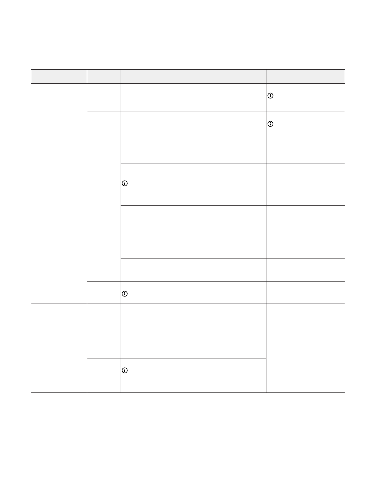
LED status and description table
Table 8: Status LEDs and Descriptions of LED States
LED Label LED Color Normal LED State Description of LED States
Off Steady = No Supply Power or the controller’s polyswitch/resettable fuse is
POWER Green On Steady
FAULT Red Off Steady
SA BUS Green Blink - 2 Hz
FC BUS Green Blink - 2 Hz
Off (Except on
EOL Amber
terminating
devices)
open. Check Output wiring for short circuits and cycle power to controller.
On Steady = Power Connected
Off Steady = No Faults
On Steady = Device Fault; no application loaded; Main Code download required,
if controller is in Boot mode, or a firmware mismatch exists between the FAC and
the ZFR1811 Wireless Field Bus Router.
Blink - 2 Hz = Download or Startup in progress, not ready for normal operation
Blink Rapidly - 5 Hz = One or more defined SA Bus devices are offline. Check SA
Bus devices for problems, including low batteries on wireless sensor.
Blink - 2 Hz = Data Transmission (normal communication)
Off Steady = No Data Transmission (N/A - auto baud not supported)
On Steady = Communication lost, waiting to join communication ring
Blink - 2 Hz = Data Transmission (normal communication)
Off Steady = No Data Transmission (auto baud in progress)
On Steady = Communication lost, waiting to join communication ring
On Steady = EOL switch in ON position
Off Steady = EOL switch in Off position
Repair information
If a field controller fails to operate within its
specifications, replace the controller. For a
replacement controller, contact your Johnson
Controls representative.
FAC2612-1 Advanced Application Field Equipment Controller Installation Guide20
Page 21

Accessories ordering information table
Table 9: Accessories ordering information
Product code number Description
MS-DIS1710-0
TP-2420 Transformer, 120 VAC Primary to 24 VAC secondary, 20 VA, Wall Plug
Y65T31-0
AS-XFR050-0 Power transformer (Class 2, 24 VAC, 50 VA maximum output), no enclosure
AP-TBK4SA-0 Replacement SA Bus Terminal Blocks, 4-Position, Brown (Bulk Pack of 10)
AP-TBK4FC-0 Replacement FC Bus Terminal Blocks, 4-Position, Blue (Bulk Pack of 10)
AP-TBK3PW-0 Replacement Power Terminal Blocks, 3-Position, Gray (Bulk Pack of 10)
MS-TBKLV03-0 Terminal Block Kit - FAC Line Voltage AC Power - 3 Pieces
MS-TBKRO02-0 Terminal Block Kit - FAC 2-Position Relay Output - 9 Pieces
MS-TBKRO03-0 Terminal Block Kit - FAC 3-Position Relay Output - 6 Pieces
MS-TBKCO04-0 Terminal Block Kit - FAC 4-Position Configurable Output - 6 Pieces
MS-TBKUI04-0 Terminal Block Kit - FAC 4-Position Universal Input - 9 Pieces
MS-TBKUI05-0 Terminal Block Kit - FAC 5-Position Universal Input - 3 Pieces
WNC1800/ZFR182x Pro Wireless
field Bus System
ZFR1800 Series Wireless Field Bus
System
NS Series Network Sensors
WRZ Series Wireless Room
Sensors
Local Controller Display (FAC devices do not support display of Schedules, Clock, Trend or Alarms
on the DIS1710 Local Controller Display)
Transformer, 120/208/240 VAC Primary to 24 VAC Secondary, 40 VA, Foot Mount, 8 in. Primary
Leads and Secondary Screw Terminals, Class 2
Note: Additional Y6x-x Series transformers are also available. Refer to the Series Y63, Y64,
Y65, Y66, and Y69 Transformers Product Bulletin (LIT-125755) for more information.
This system is used forinstallations that support BACnet/IP but can also coexist with theZFR1800
Series when installed under the same supervisor (for example, ,network engine). Refer to the
WNC1800/ZFR182x ProSeries Wireless Field Bus System Product Bulletin (LIT-12012320)for a list of
availableproducts.
This system is used for installationsthat only support BACnet MS/TP. Refer to the ZFR1800 Series
Wireless Field BusSystem Product Bulletin (LIT-12011336) for a list of availableproducts.
Refer to the NS Series Network Sensors Product Bulletin (LIT-12011574) for specific sensor model
descriptions.
Refer to the WRZ Series Wireless Room Sensors Product Bulletin (LIT-12000653) for specific sensor
model descriptions.
FAC2612-1 Advanced Application Field Equipment Controller Installation Guide 21
Page 22

Technical specifications
Table 10: FAC2612-1 Field Application Controller
Product Code Numbers MS-FAC2612-1 Field Application Controller
24 VAC (nominal, 20 VAC minimum/30 VAC maximum), 50/60 Hz,
Supply Voltage
Power Consumption
Ambient Conditions
Controller Addressing for
BACnet MS/TP
Controller Addressing for N2
power supply Class 2 (North America), Safety Extra-Low Voltage (SELV)
(Europe)
25 VA maximum for FAC2612-1 (no integral display)
Note: VA rating does not include any power supplied to the
peripheral devices connected to Binary Outputs (BOs) or
Configurable Outputs (COs), which can consume up to 12 VA for
each BO or CO; for a possible total consumption of an additional
84 VA (maximum).
Operating: 0°C to 50°C (32°F to 122°F); 10% to 90% RH noncondensing;
Pollution Degree 2
Storage: -40°C to 80°C (-40°F to 176°F); 5% to 95% RH noncondensing
DIP switch set; valid field controller device addresses 4–127 (Device
addresses 0–3 and 128–255 are reserved and not valid field controller
addresses.)
DIP switch set; valid control device addresses 1-255
Note: Refer to the Modernization Guide for Legacy N2 Controllers
(LIT-12012005) for address information when using the controller
on an N2 bus.
RS-485: Selectable BACnet® MS/TP or N2:
3-wire FC Bus between the supervisory controller and field controllers
Communications Bus
4-wire SA Bus between controller, network sensors and other sensor/
actuator devices, includes a lead to source 15 VDC supply power (from
controller) to bus devices.
Processor H8SX/166xR Renesas® 32-bit microcontroller
Memory 4 MB flash memory and 1 MB RAM
5 - Universal Inputs: Defined as 0-5 VDC, 4-20 mA, 0-600k ohm, or
Binary Dry Contact
4 - Binary Inputs: Defined as Dry Contact Maintained or Pulse
Counter/Accumulator Mode
Input and Output Capabilities
4 - Configurable Outputs: Defined as 0-10 VDC or 24 VAC Triac BO
2 - Relay Outputs: (Single-Pole, Double-Throw); UL 916: 1/4 hp 120
VAC, 1/2 hp 240 VAC; 360 VA Pilot Duty at 120/240 VAC (B300); 3 A Noninductive 24-240 VAC; EN 60730: 6 (4) A N.O. or N.C. only
Analog Input/Analog Output
Resolution and Accuracy
Input: 16-bit resolution
Output: 16-bit resolution, +/- 200 mV accuracy in 0-10 VDC applications
FAC2612-1 Advanced Application Field Equipment Controller Installation Guide22
Page 23

Table 10: FAC2612-1 Field Application Controller
Input/Output: Pluggable Screw Terminal Blocks
Terminations
SA/FC Bus and Supply Power: 4-Wire and 3-Wire Pluggable Screw
Terminal Blocks
SA/FC Bus Port: RJ-12 6-Pin Modular Jacks
Mounting
Horizontal on single 35 mm DIN rail mount (preferred), or screw mount
on flat surface with three integral mounting clips on controller
Enclosure material: ABS and polycarbonate UL94 5VB; Self-
Housing
extinguishing
Protection Class: IP20 (IEC529)
150 mm x 164 mm x 53 mm (5-7/8 in. x 7-1/2 in. x 2-1/8 in.) including
terminals and mounting clips
Dimensions (Height x Width x
Depth)
Note: Mounting space requires an additional 50 mm (2 in.) space
on top, bottom and front face of controller for easy cover removal,
ventilation and wire terminations.
Weight 0.5 kg (1.1 lb)
United States: UL Listed, File E107041, CCN PAZX, UL 916, Energy
Management Equipment
Compliance
FCC Compliant to CFR47, Part 15, Subpart B, Class A
Canada: UL Listed, File E107041, CCN PAZX7 CAN/CSA C22.2 No.205,
Signal Equipment
Industry Canada Compliant, ICES-003
Europe: CE Mark – Johnson Controls declares that this product is
in compliance with the essential requirements and other relevant
provisions of the EMC Directive.
Australia and New Zealand: RCM Mark, Australia/NZ Emissions
Compliant
BACnet International: BACnet Testing Laboratories (BTL) Protocol
Revision 7 Listed BACnet Application Specific Controller (B-ASC)
The performance specifications are nominal and
conform to acceptable industry standard. For
application at conditions beyond these specifications,
consult the local Johnson Controls® office. Johnson
Controls shall not be liable for damages resulting from
misapplication or misuse of its products.
Product warranty
This product is covered by a limited
warranty, details of which can be found at
www.johnsoncontrols.com/buildingswarranty.
Single point of contact
APAC Europe NA/SA
JOHNSON CONTROLS
C/O CONTROLS PRODUCT
MANAGEMENT
NO. 32 CHANGJIJANG RD NEW
DISTRICT
WUXI JIANGSU PROVINCE 214028
CHINA
For more contact information, refer to
www.johnsoncontrols.com/locations.
JOHNSON CONTROLS
WESTENDHOF 3
45143 ESSEN
GERMANY
JOHNSON CONTROLS
507 E MICHIGAN ST
MILWAUKEE WI 53202
USA
FAC2612-1 Advanced Application Field Equipment Controller Installation Guide 23
Page 24

© 2019 Johnson Controls. All rights reserved. All specifications and other information shown were current as of document revision and
are subject to change without notice.
www.johnsoncontrols.com
 Loading...