

Page 1
Installation Instructions F61
Issue Date July 30, 2002
F61 Series Standard Flow Switches
Installation
IMPORTANT: All F61 Series Flow Switches are
intended to control equipment under normal
operating conditions. Where failure or malfunction of
an F61 Flow Switch could lead to an abnormal
operating condition that could cause personal injury
or damage to the equipment or other property, other
devices (limit or safety controls) or systems (alarm or
supervisory) intended to warn of, or protect against,
failure or malfunction of the F61 Flow Switch must
be incorporated into and maintained as part of the
control system.
Some models of the F61 Series Standard Flow
Switches require installation or adjustment of paddles
prior to mounting. See Installing the Flow Paddles.
Parts Included
Standard models of the F61 flow switch include an
installed three-piece flow paddle. Some models also
include a large flow paddle for large pipe sizes.
Table 1: Replacement Parts
Kit Number Description
KIT21A-600
KIT21A-601
PLT52A-600R
CVR62A-600R Replacement Cover Assembly for LB,
Stainless Steel Three-piece Paddle
(3 in., 2 in., and 1 in. Segments)
Stainless Steel 6 in. Paddle
Stainless Steel Three-piece Paddle
(3 in., 2 in., and 1 in. Segments) and
6 in. Paddle
MB, MD, and MG types
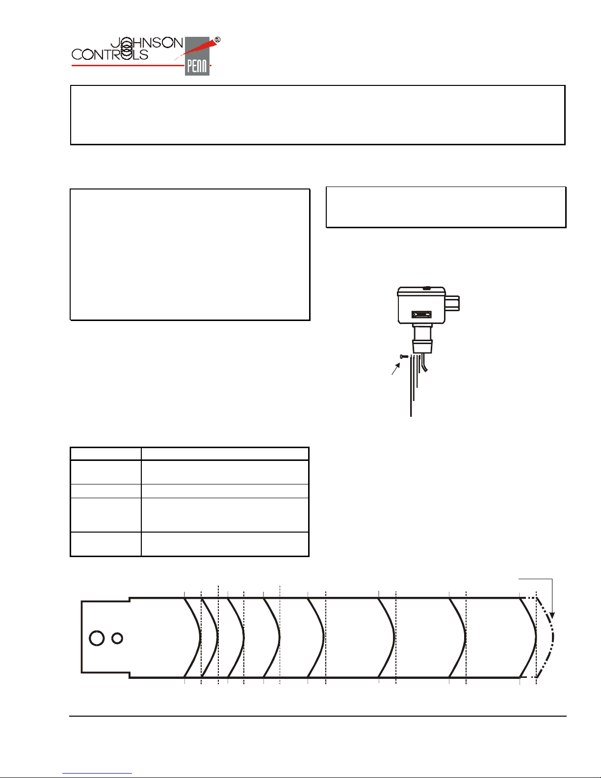
Installing the Flow Paddles
IMPORTANT: To allow the switch to detect changes
in the fluid flow, the flow paddle must not touch the
pipe or any restrictions in the pipe.
Adjust flow paddles to the size of the pipe used. If
needed, trim the large flow paddle at the arc
corresponding to pipe size (see Figure 1 and Figure 2)
and install.
Flow
Paddle
Screw
Trim flow paddles to fit
pipe diameter or remove
flow paddles that are
too large to fit pipe diameter.
Figure 1: Installing the Paddles
1 in.
Figure 2: Trimming Diagram for Large Flow Paddle
© 2002 Johnson Controls, Inc.
Part No. 24-8407-4, Rev. C www.johnsoncontrols.com
1-1/2 in.
2 in.
2-1/2 in.
4 in.3 in.
5 in.
Original
Length
6 in.
1
Page 2
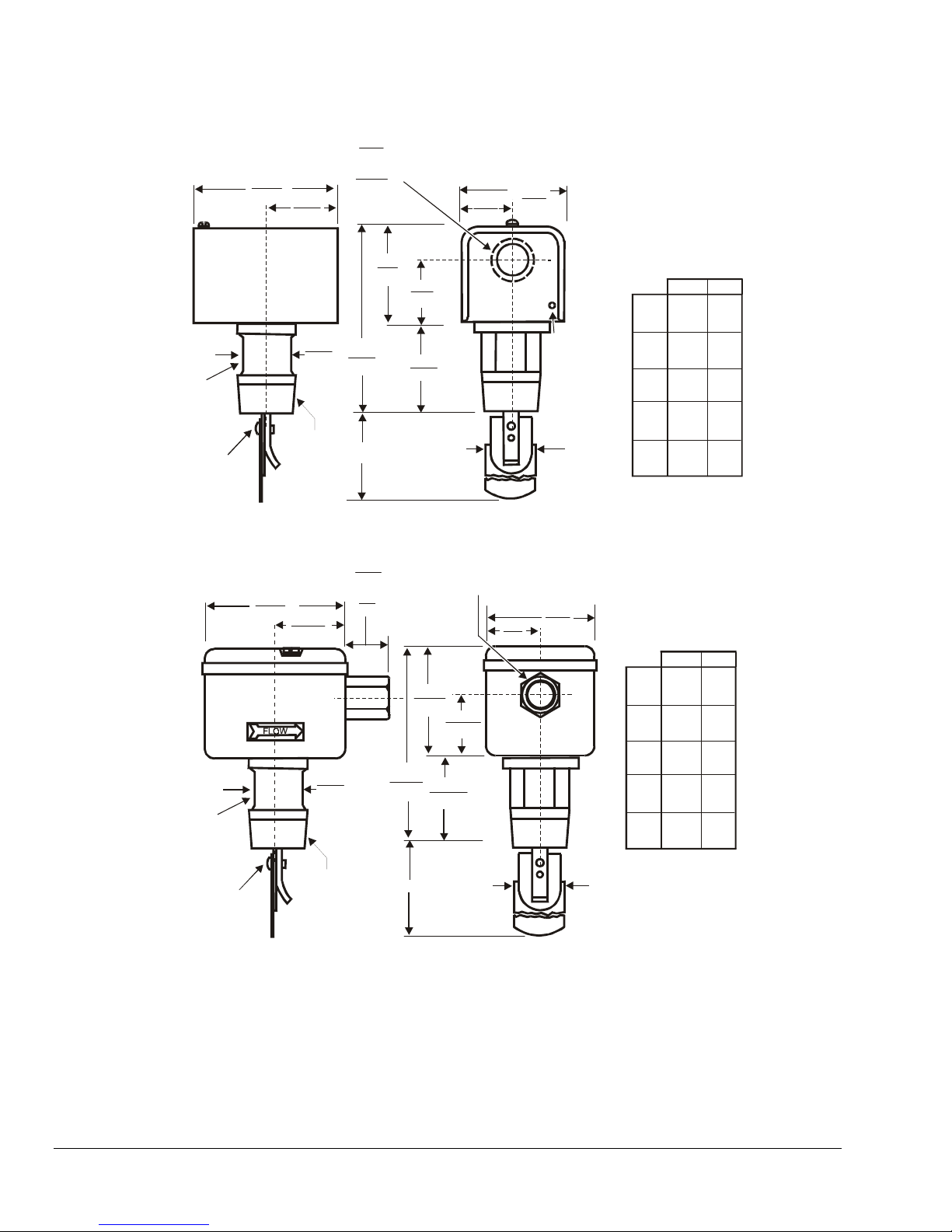
Dimensions
4
(102)
2
(51)
7/8
Diameter Hole for 1/2 in. Trade Size Conduit
(22)
1-1/16
Diameter Knockout Ring for 3/4 in. Trade Size Conduit
(27)
1-3/8
(35)
2-3/4
(71)
Use these
wrench flats
to tighten
the flow switch
at installation.
Paddle
Screw
Figure 3: NEMA 1 Enclosure (F61KB Types) Dimensions, in./mm
Use these
wrench flats
to tighten
the flow switch
at installation.
Paddle
Screw
3-11/16
(94)
1-1/4
4-3/4
(33)
(121)
1 in.
11-1 / 2 NP T
1-13/16
(47)
1-1/4
(33)
1 in. 11-1/2 NPT
2-11/16
(68)
1-3/4
(44)
1-1/8
(29)
A
1-1/8
On MB and MG Types
(29)
5/8
On LB Types
(15)
2-7/8
(73)
4-3/4
(121)
A
B
1/2-14 NPSM Thread
1-3/8
(35)
1-9/16
(40)
1-1/16
(27)
B
Grounding
Screw
Hole
2-3/4
(71)
Dimension by
Liquid Line Size
1-7/16
1
(37)1 (25)
(25)
2-1/2
2
(64)
(51)
3-1/2
3
(89)
(76)
4
6-5/8
(101)
(168)
5
6-5/8
(152)
(168)
Dimension by
Liquid Line Size
1-7/16
1
(37)1 (25)
(25)
1-1/8
2-1/2
2
(64)
3-1/2
(89)
6-5/8
(168)
6-5/8
(168)
(29)
1-1/8
(29)
1-1/8
(29)
1-1/8
(29)
(51)
3
(76)
4
(101)
5
(152)
BA
1-1/8
(29)
1-1/8
(29)
1-1/8
(29)
1-1/8
(29)
BA
Figure 4: NEMA 3 or NEMA 3R Enclosure (F61LB, F61MB, F61MG Types) Dimensions, in./mm
2 F61 Series Standard Flow Switches Installation Instructions
Page 3
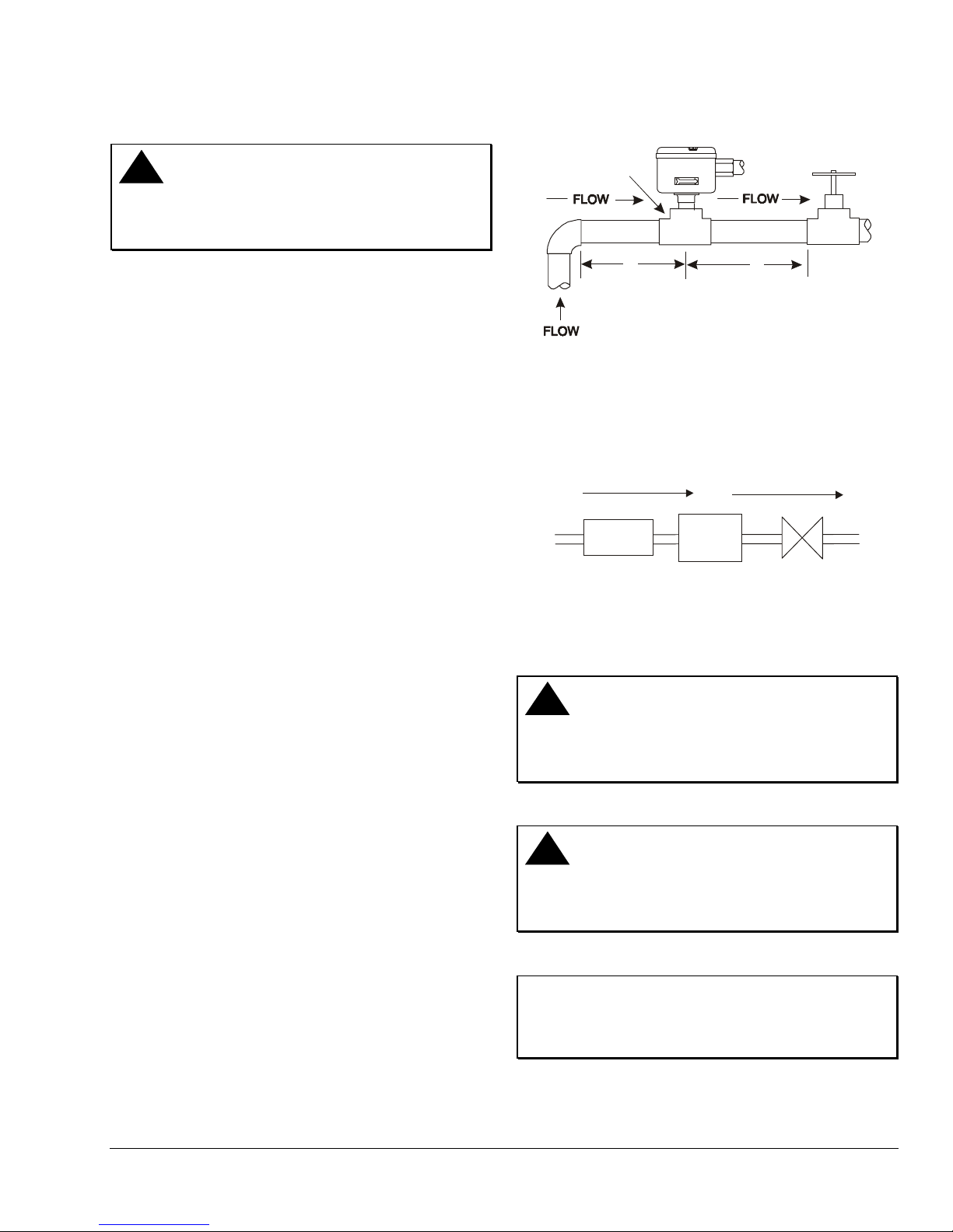
Mounting
!
CAUTION: Risk of Equipment Damage.
To avoid damaging the switch, do not tighten the
switch to the tee by grasping the switch enclosure.
Use only the wrench flats provided.
Tee or Welded
Half-coupling
Mount the F61 Series Flow Switch, using the following
guidelines:
• Install the switch so that the cover and interior are
accessible.
• Mount the switch so that the flow of fluid is in the
direction of the arrow on the switch casing.
• Use a pipe union on each side of the flow switch to
allow easy removal or replacement.
• Mount the switch so that the pipe does not extend
too far into the flow switch casing.
• Use pipe thread sealer on male threads only.
• Do not remove the cover gasket or the wire
grommet from the conduit opening.
For 1 in. pipe installation, mount the F61 flow switch in
a standard 1 in. x 1 in. x 1 in. tee. For larger sizes of
pipe, use a reducing tee to keep the flow switch close
to the pipe and provide adequate paddle length in the
flow stream.
Example: Use a 2 in. x 2 in. x 1 in. tee for a
2 in. pipe. If a standard 2 in. x 2 in. x 2 in. tee is
used, install a face or hex bushing in the top
opening to reduce it to 1 in.
Mount the flow switch so the terminals or wire leads
are easily accessible for wiring. Screw the flow switch
in position so the flat of the paddle is at a right angle to
the flow. The arrow on the side of the case must point
in the direction of the flow.
A
Dimension must be at least
five pipe diameters from the nearest
elbow, valve, or other pipe restriction.
A
A
Figure 5: Required Piping Distance
Do not subject the flow switches to water hammer.
Use a suitable water hammer arrester if a fast-closing
valve is located downstream of the flow switch. See
Figure 6.
Flow
Flow
Switch
Water
Hammer
Arrester
Val ve
Figure 6: Water Hammer Arrester Location
Schematic
Wiring
!
WARNING: Risk of Electrical Shock.
Disconnect power supply before making electrical
connections. Failure to follow this precaution may
result in electrical shock or death.
Location Considerations
Mount the F61 flow switch in a horizontal pipeline or a
vertical pipeline with upward fluid flow. Do not use in a
vertical pipeline with downward flow. When mounted in
a vertical pipe with upward flow, the switch trips at a
slightly higher flow than shown in Table 3 through
Table 6, due to the effect of gravity on the switch
mechanism.
Mount the F61 flow switch in a section of pipe where
there is a straight run of at least five pipe diameters on
each side of the flow switch from the nearest elbow,
valve, or other pipe restriction. See Figure 5.
!
CAUTION: Risk of Equipment Damage.
Using terminal screws other than those provided will
void the warranty and may damage the switch. Use
only the terminal screws furnished.
IMPORTANT: To prevent moisture from entering
and condensate from forming inside the NEMA 3R
enclosure, do not remove the cover gasket or the
wire grommet from the conduit opening.
F61 Series Standard Flow Switches Installation Instructions 3
Page 4

IMPORTANT: Install all wiring in accordance with
the National Electrical Code and local regulations.
Make all wiring connections using copper conductors
only. Do not exceed the control’s electrical rating.
The F61KB and F61LB models have three color-coded
terminals. Red is common. See Table 2 and Figure 1
for switch action.
The F61MB and F61MG models have four color-coded
wire leads. Red is common, green is ground. See
Table 2.
!
CAUTION: Risk of Equipment Damage.
Sealed settings (screws marked with black paint) are
not intended to be changed. Adjustment attempts
may damage the control or cause loss of calibration,
voiding the warranty.
To adjust the setting of the flow switch:
1. Disconnect power supply before making electrical
connections.
Table 2: Switch Action
Flow Action Switch Closure
Increase
Decrease
Increase in Flow
Above Setpoint
Red
Ye ll ow
Blue
Red to Yellow
Red to Blue
Decrease in Flow
Above Setpoint
Figure 7: Switch Action
Setup and Adjustments
!
WARNING: Risk of Electrical Shock.
Disconnect power supply before making electrical
connections. Failure to follow this precaution may
result in electrical shock or death.
2. Remove the F61 flow switch cover.
3. Turn the adjusting screw clockwise to raise the
flow rate. Turn the adjusting screw
counterclockwise to lower the flow rate. See
Figure 8.
4. Replace the cover after completing adjustments.
Tighten the cover screws to 12 in⋅lbs of torque.
Note: Do not lower the flow rate unless it has been
raised from the factory setting.
Lower Flow Rates
Less liquid flow
required to switch
from R-Y to R-B.
Adjusting Screw
Higher Flow Rates
More liquid flow
required to switch
Red
Blue
from R-Y to R-B.
Yellow
Figure 8: Flow Rate Adjustment
!
CAUTION: Risk of Improper Operation.
The switch is factory set at approximately the
minimum flow rate (see Table 3 through Table 6).
Do not set lower than the factory setting because
that may result in the switch failing to return to a no
flow position.
4 F61 Series Standard Flow Switches Installation Instructions
Page 5

To verify that the flow rate is set above the factory
minimum (see Figure 9):
1. depress the main lever numerous times. If the
lever fails to click upon return at any time, the flow
rate is set below the factory-set minimum.
2. raise the flow rate to approximately the factory
minimum by turning the adjusting screw clockwise
until the lever clicks upon return every time.
Typical Flow Rates for Standard F61 Flow Switches
Table 3: F61KB, F61LB, and F61MB Models, 1-3 in. Paddles
GPM (m
Pipe Size (in.) 1 1-1/411-1/2
Flow
Increase
(R to Y
Minimum
Adjustment
Maximum
Adjustment
1. Values for 2 in. paddle trimmed to fit pipe.
2. Values for 3 in. paddle trimmed to fit pipe.
3. Values calculated for factory-installed set of 1, 2, and 3 in. paddles.
Closes)
Flow
Decrease
(R to B
Closes)
Flow
Increase
(R to Y
Closes)
Flow
Decrease
(R to B
Closes)
4.20
(0.95)
2.50
(0.57)
8.80
(2.0)
8.50
(1.93)
5.80
(1.32)
3.70
(0.84)
13.3
(3.02)
12.5
(2.84)
3
/hr) Required to Actuate Switch
1
22-1/223435
7.50
(1.70)
5.00
(1.14)
19.2
(4.36)
18.0
(4.09)
13.7
(3.11)
9.50
(2.16)
29.0
(6.59)
27.0
(6.13)
18.0
(4.09)
12.5
(2.84)
34.5
(7.84)
32.0
(7.27)
Adjusting
Screw
Figure 9: Minimum Adjustment
27.5
(6.24)
19.0
(4.32)
53.0
(12.0)
50.0
(11.4)
65.0
(14.8)
50.0
(11.4)
128
(29.1)
122
(27.7)
3
125
(28.4)
101
(22.9)
245
(55.6)
235
(53.4)
3
6
190
(43.2)
158
(35.9)
375
(85.2)
360
(81.8)
Main
Lever
3
8
375
(85.2)
320
(72.7)
760
(173)
730
(166)
Table 4: F61KB, F61LB, and F61MB Models, 6 in. Paddles*
Pipe Size (in.) 4568
Minimum
Adjustment
Maximum
Adjustment
* Where paddle size is larger than pipe size, values are for 6 in. paddle trimmed to fit pipe.
Flow Increase (R to Y Closes) 37.0 (8.40) 57.0 (12.9) 74.0 (16.8) 205 (46.6)
Flow Decrease (R to B Closes) 27.0 (6.13) 41.0 (9.31) 54.0 (12.3) 170 (38.6)
Flow Increase (R to Y Closes) 81.0 (18.4) 118 (26.8) 144 (32.7) 415 (94.3)
Flow Decrease (R to B Closes) 76.0 (17.3) 111 (25.2) 135 (30.7) 400 (90.8)
GPM (m3/hr) Required to Actuate Switch
F61 Series Standard Flow Switches Installation Instructions 5
Page 6

Table 5: F61MG Models, 1-3 in. Paddles
GPM (m
Pipe Size (in.) 1 1-1/411-1/2
Flow
Increase
(R to Y
Minimum
Adjustment
Maximum
Adjustment
1. Values for 2 in. paddle trimmed to fit pipe.
2. Values for 3 in. paddle trimmed to fit pipe.
3. Values calculated for factory-installed set of 1, 2, and 3 in. paddles.
Closes)
Flow
Decrease
(R to B
Closes)
Flow
Increase
(R to Y
Closes)
Flow
Decrease
(R to B
Closes)
3.80
(0.86)
2.50
(0.57)
8.70
(1.98)
8.50
(1.93)
5.30
(1.20)
3.70
(0.84)
13.1
(2.98)
12.5
(2.84)
3
/hr) Required to Actuate Switch
1
22-1/223435
6.90
(1.57)
5.00
(1.14)
18.8
(4.27)
18.0
(4.09)
12.7
(2.88)
9.50
(2.16)
28.9
(6.56)
27.0
(6.13)
16.7
(3.79)
12.5
(2.84)
33.7
(7.65)
32.0
(7.27)
24.3
(5.52)
19.0
(4.32)
52.1
(11.8)
50.0
(11.4)
61.0
(13.8)
50.0
(11.4)
126
(28.6)
122
(27.7)
Table 6: F61MG Models, 6 in. Paddles*
GPM (m
3
/hr) Required to Actuate Switch
Pipe Size (in.) 4568
Minimum
Adjustment
Maximum
Adjustment
* Where paddle size is larger than pipe size, values are for 6 in. paddle trimmed to fit pipe.
Flow Increase (R to Y Closes) 35.0 (7.95) 53.0 (12.0) 69.0 (15.7) 197 (44.7)
Flow Decrease (R to B Closes) 27.0 (6.13) 41.0 (9.31) 54.0 (12.3) 170 (38.6)
Flow Increase (R to Y Closes) 80.0 (18.2) 116 (26.3) 142 (32.2) 412 (93.6)
Flow Decrease (R to B Closes) 76.0 (17.3) 111 (25.2) 135 (30.7) 400 (90.8)
3
118
(26.8)
101
(22.9)
243
(55.2)
235
(53.4)
3
6
183
(41.6)
158
(35.9)
372
(84.5)
360
(81.8)
3
8
362
(82.2)
320
(72.7)
753
(171)
730
(166)
Checkout
IMPORTANT: Ensure installation, wiring, and control
settings are according to the application
requirements. Refer to the controlled system’s
manufacturer specifications for the proper settings
when adjusting these controls.
Apply power to the control and controlled equipment.
Cycle the controlled system at least three times at
normal operating conditions.
The circuit between the red and the yellow leads
(terminals) closes when sufficient fluid flows through
the pipe to trip the F61 flow switch.
6 F61 Series Standard Flow Switches Installation Instructions
Page 7

Troubleshooting
Use the information in Table 7 to troubleshoot the flow
switch.
Table 7: Troubleshooting
Symptom/Problem Solution
Water (condensate) is within the enclosure.
Fluid from the tank is leaking into enclosure due to
bellows failure.
Switch does not activate due to debris caught within
the switch mechanism.
Control switch action is reversed.
Repairs and Replacement
Do not make field repairs, except for replacement of
the cover and paddles. For a replacement flow switch,
paddle kit or cover, contact the nearest
Johnson Controls/PENN™ distributor. For more
information, contact Refrigeration Application
Engineering at (800) 275-5676.
Use a model with a NEMA 3R enclosure. If using a model with
a NEMA 3R enclosure, inspect the grommet in the conduit
fitting. Replace grommet if defective.
Replace flow switch.
Clear any debris within the switch mechanism. Test the
operation of switch several times for proper operation.
Ensure connections follow wiring diagrams.
Control does not switch.
Switch fails to return to the no flow position.
Control does not switch on flow increase.
Switch is set lower than the factory setting. Increase the setting.
On vertical pipes, ensure that direction of flow is up. The arrow
on switch must point in direction of flow (up).
Check for cracked/broken paddle. Replace if necessary.
Check connections.
Electrical Ratings
Table 8: Electrical Ratings for F61KB, F61LB, and F61MB Models
Electrical Ratings 120 VAC 208 VAC 240 VAC 277 VAC
Horsepower
Full Load Amperes
Locked Rotor Amperes
Non-inductive Amperes
Pilot Duty
Table 9: Electrical Ratings for F61MG Models
Electrical Ratings 120 VAC
Full Load Amperes
Locked Rotor Amperes
Non-inductive Amperes
Pilot Duty
111-
16.0 8.8 8.0 -
96.0 52.8 48.0 -
16.0 16.0 16.0 16.0
125 VA at 24/277 VAC
1
6
2
125 VA at 24/277 VAC
F61 Series Standard Flow Switches Installation Instructions 7
Page 8

Technical Specifications
Product
Maximum Fluid Pressure
Minimum Fluid
Temperature
Maximum Fluid
Temperature
Switch
Wiring Connections
Pipe Connector
Conduit Connection
F61 Series Standard Flow Switches
150 psig (1034 kPa)
32°F (0°C) (F61KB, F61LB)
-20°F (-29°C) (F61MB, F61MG)
250°F (121°C)
Single Pole Double Throw
Screw Type Terminals (F61KB, F61LB)
Four Color-coded No. 14 AWG Solid Conductor Wire Leads, 7 in. (178 mm) Long (F61MB,
F61MG)
1 in. 11-1/2 NPT Threads
One 7/8 in. (22 mm) Hole for 1/2 in. Conduit with 1-1/8 in. (29 mm) Knockout Ring for
3/4 in. Conduit (F61KB)
Female Hub for 1/2 in. Conduit, 1/2-14 NPSM Threads (F61LB, F61MB, F61MG)
Agency
Listings
UL Listed
CSA
Certified
E5368, CCN NMFT
LR948, Class 3211 06, Class 4813 02, Class 1222 01 (F61KB)
(F61LB - Not CSA Certified)
LR948, Class 3211 06 (F61MB, F61MG)
Shipping Weight
The performance specifications are nominal and conform to acceptable industry standards. For application at conditions beyond these
specifications, consult the local Johnson Controls office. Johnson Controls, Inc. shall not be liable for damages resulting from misapplication or
misuse of its products.
Refer to the F61 Series Flow Switches Product/Technical Bulletin (LIT-125225) for necessary information on operating and performance
specifications of this product.
2.8 lb (1.3 kg)
Controls Group
507 E. Michigan Street
P.O. Box 423 Printed in U.S.A.
Milwaukee, WI 53201 www.johnsoncontrols.com
8 F61 Series Standard Flow Switches Installation Instructions
 Loading...