

Page 1

F240EA Pneumatic Liquid Flow Switch
Installation Instructions
Part No. 24-7664-3132, Rev. A
Issued October 15, 2015
Refer to the QuickLIT website for the most up-to-date version of this document.
Applications
IMPORTANT: Do not use F240EA Pneumatic
Liquid Flow Switches with fluids that are
incompatible with the wetted materials (forged
normal brass, free machining bronze, and Viton®)
and which are classed as a hazardous material. Use
in this condition may cause malfunction or improper
operation.
IMPORTANT: Do not use F240EA Pneumatic
Liquid Flow Switch where the fluid in the pipes drops
below the fluid’s freezing point, causing an internal
freeze-up.
IMPORTANT: Use thi s F240EA Pneumatic Liquid
Flow Switch only as an operating control. Where
failure or malfunction of the flow switch could lead to
personal injury or property damage to the controlled
equipment or other property , additional precautions
must be designed into the control system. Incorporate
and maintain other devices, such as supervisory or
alarm systems or safety or limit controls, intended to
warn of or protect against failure or malfunction of the
flow switch.
IMPORTANT: Utiliser ce F240EA Pneumatic Liquid
Flow Switch uniquement en tant que dispositif de
régulation. Lorsqu'une défaillance ou un
dysfonctionnement du flow switch risque de
provoquer des blessures ou d'endommager
l'équipement contrôlé ou un autre équipement, la
conception du système de contrôle doit intégrer des
dispositifs de protection supplémentaires. Veiller
dans ce cas à intégrer de façon permanente
d'autres dispositifs, tels que des systèmes de
supervision ou d'alarme, ou des dispositifs de
sécurité ou de limitation, ayant une fonction
d'avertissement ou de protection en cas de
défaillance ou de dysfonctionnement du flow switch.
The F240EA switch uses a variety of paddle sizes to
respond to liquid flow rates in applications with pipe
sizes greater than 1-inch trade size. The paddle has
three segments. You can remove (or trim) the paddle
segments for pipe sizes under 3 inches. A 6 in. paddle
that can be trimmed for 4 in. and 5 in. pipe is available.
The F240EA Pneumatic Liquid Flow Switch acts as an
automatic operating control in air conditioning, heating
and cooling water systems and in processing work.
Typical applications include:
• Flow detection switch to start the refrigeration
compressor on a liquid chiller system when flow
has been established.
• Signal or alarm switch to indicate when the pump
on a condenser cooling water system shuts down.
• Proving the flow of water before an electric
immersion heater is turned on.
Installation
The F240EA Pneumatic Liquid Flow Switch is
packaged with 1 in., 2 in., and 3 in. stainless steel flow
paddles along with a paddle screw and lock washer.
See Table 2 for replacement parts.
IMPORTANT: The flow paddle must not touch the
pipe or any restrictions in the pipe. If the flow paddle
touches the pipe (or restrictions in the pipe), the
switch may not be able to properly detect changes in
fluid flow.
Adjust the flow paddles to the size of the pipe used.
Install the large flow paddle, if needed. Trim the flow
paddle at the arc corresponding to the pipe size. See
Figure 1, Figure 2, Figure 3, and Table 1.
The F240EA Pneumatic Liquid Flow Switch detects the
increase or decrease of liquid flow in a pipe. The
F240EA switch responds to liquid flow in a pipe that
carries water, ethylene glycol, or other nonhazardous
fluids.
F240EA Pneumatic Liquid Flow Switch Installation Instructions
1
Page 2
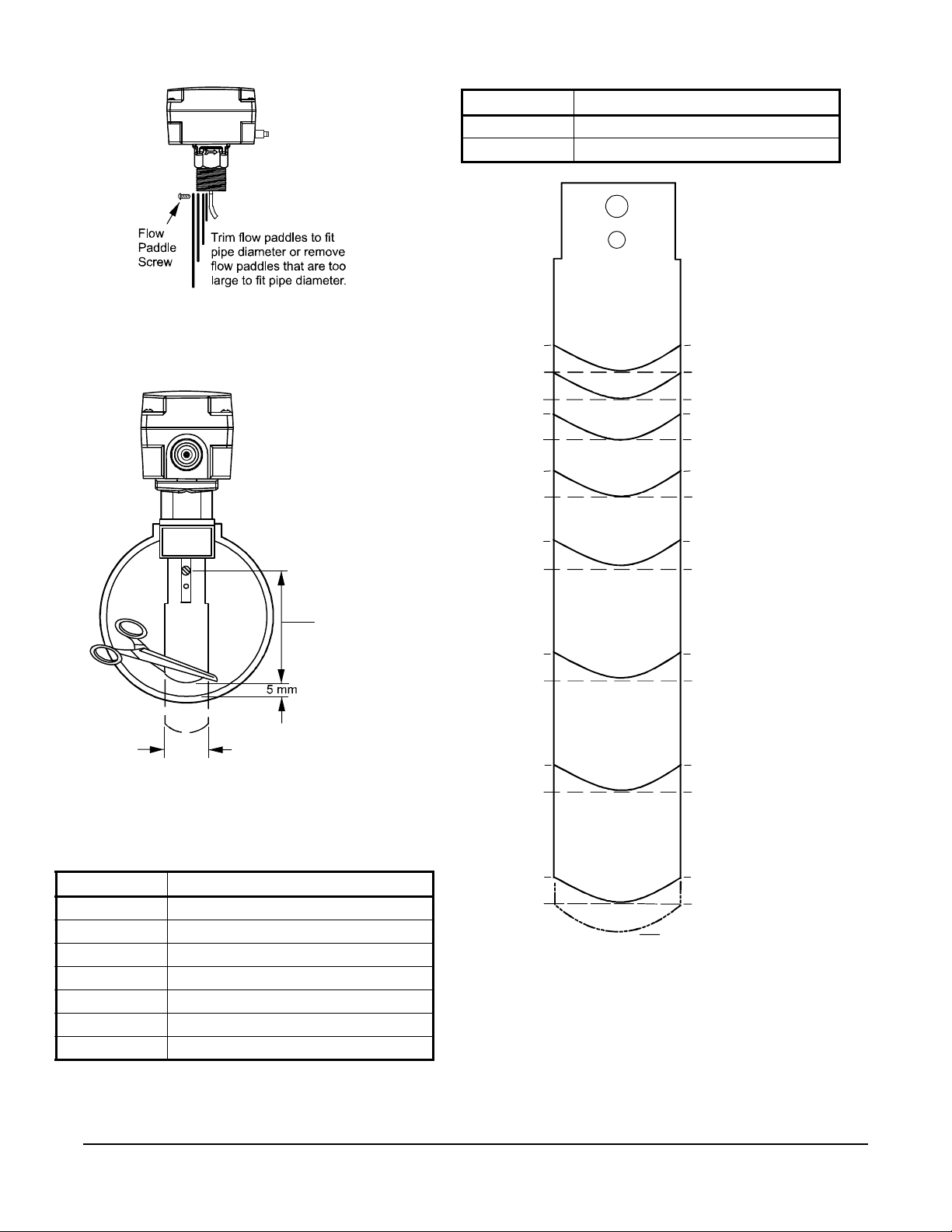
Figure 1: Installing the Flow Paddles
FIG:in stl_fl w_pddl
Figure 2: Trimming the Flow Paddles
2 in. [
3 in. [
4 in. [
5 in. [
6 in.
37 mm]
43 mm]
54 mm]
67 mm]
83 mm]
103 mm]
134 mm]
b
1 in. padd le
Figure 3: Trimming Diagram for the Large Flow
Paddle
2 in. pipe
1 in. pipe
Original Length
FIG:pdd l_tmpl t
Note: Allow a minimum clearance of 3/16 in. (5 mm)
between the end of the flow paddle and the pipe wall.
Table 1: Trimming the Flow Paddles (Part 2 of 2)
Paddle Size Use or Trim This Paddle to Fit
5 in. 6 in.
6 in. 6 in.
1-1/2 in. pipe
FIG:trm_f lw_pddl_ F240EA
1 in. [
1-1/4 in. [
1-1/2 in. [
2-1/2 in. [
b = 25 mm fo r th e
b = 29 mm fo r th e paddle 2, 3, or 6 in .
29 mm]
[162 mm]
Table 1: Trimming the Flow Paddles (Part 1 of 2)
Paddle Size Use or Trim This Paddle to Fit
1 in. 1 in.
1-1/4 in. 2 in.
1-1/2 in. 2 in.
2 in. 2 in.
2-1/2 in. 3 in.
3 in. 3 in.
4 in. 6 in.
2-1/2 in. pipe
3 in. pipe
4 in. pipe
5 in. pipe
6 in. pipe
F240EA Pneumatic Liquid Flow Switch Installation Instructions
2
Page 3

Dimensions
Figure 4: Dimensions for F240EA Standard Flow Switch, in. [mm]
FIG:dmnsns_F240EA
[54]
[66]
1-3/8
[35]
2-3/4
[70]
1/2 [13]
Typical
Thread
Engagement
30mm Hex
3-1/2
[89]
4-1/2
[114]
5-11/16
[144]
1-1/8
[28]
4
[102]
2
[51]
4-9/16
[116]
Barbed connector for
1/4 [6] O.D. x
3/16 [4] I.D.
tubing
1-11 1/2 NPT
3/4
[18]
2-1/8
2-9/16
Accessories
Table 2: Replacement Paddle Parts
Product Code
Number
KIT21A-600 Stainless steel 3-piece paddle (3 in., 2 in., and 1 in. segments)
KIT21A-601 Stainless steel 6 in. paddle
KIT21A-602 Stainless steel 3-piece paddle (3 in., 2 in., and 1 in. segments) and Stainless steel 6 in. paddle
Description
F240EA Pneumatic Liquid Flow Switch Installation Instructions
3
Page 4

Mounting
Figure 5: Use Only the Wrench Flats Provided
Figure 6: Flow Direction for Vertical Mounting
Figure 7: Required Piping Distance
FLOW FLOW
FLOW
Dimension must be at le ast
A
Tee or Welded
Half-Coupling
FIG:ppng_dst
IMPORTANT: To avoid damaging the switch, do
not tighten the switch to the tee by grasping the
switch enclosure. Use only the wrench flats
provided.
Location Considerations
FIG:wrnch_flts
FIG: Flw_di r_F240EA
IMPORTANT: Do not use in a vertical pipeline with
a downward flow (Figure 6).
Mount the F240EA Pneumatic Liquid Flow Switch
using the following guidelines:
• Install the switch so that the enclosure and interior
are accessible.
• Mount the switch so that the flow of the fluid is in
the direction of the arrow on the enclosure.
• Use a pipe union on each side of the flow switch to
allow for easy removal or replacement.
• Do not allow the pipe to extend too far into the flow
switch casing.
• Use pipe thread sealer or Teflon® tape on the male
threads only.
For standard 1 in. x 1 in. pipe installation, mount the
F240EA Pneumatic Liquid Flow Switch in a standard 1
in. x 1 in. x 1 in. tee. For larger sizes of pipe, use a
reducing tee to keep the flow switch close to the pipe
and provide adequate paddle length in the flow stream.
Example: Use a 2 in. x 2 in. x 1 in. tee for a 2 in.
pipe. If a standard 2 in. x 2 in. x 2 in. tee is used,
install a face or hex bushing in the top openin g to
reduce the top opening to 1 in.
Mount the F240EA Pneumatic Liquid Flow Switch in a
horizontal pipeline or a vertical pipeline with upward
fluid flow. When mounted in a vertical pipe with an
upward flow, the switch trips at a slightly higher flow
than shown in Table 3 and Table 4, due to the effect of
gravity on the switch mechanism.
Mount the F240EA Pneumatic Liquid Flow Switch in a
section of pipe where there is a straight run of at least
5 pipe diameters from the nearest elbow, valve, or
other pipe restriction (Figure 7).
nc_F240EA
five pipe diameters from the near est
elbow, valve, or other pipe r estriction.
When mounting the flow switch on horizontal pipe,
mount the flow switch within 60 degrees of vertical. See
Figure 8.
F240EA Pneumatic Liquid Flow Switch Installation Instructions
Note: Do not subject the flow switches to water
hammer. Use a suitable water hammer arrester if a
fast-closing valve is located downstream of the switch.
See Figure 9.
4
Page 5

!
Figure 8: Angle Allowed
120° up
60°
from
vertical
60°
from
FIG:mtg_ang l_F240EA
Figure 9: Water Hammer Arrester Location
FLOW
Hammer
Arrester
!
Figure 10: Flow Rate Adjustment
(Screw)
Flow Rat e
Higher
Less water flow
required to
activate switchthe
required to
water
-
Water
vertical
FLOW
CAUTION: Risk of Property Damage.
Do not attempt to change sealed
settings. Attempted adjustment may
damage the control or cause loss of
calibration or other property damage.
MISE EN GARDE : Risque de dégâts
matériels.
Ne pas essayer de modifier la position
des éléments de réglage bloqués. Toute
tentative de réglage risque
d'endommager le dispositif de contrôle
ou de provoquer la perte des valeurs
d'étalonnage ou d'autres dégâts
matériels.
Lower
Flow Rate
More flow
activate the switch
Adjustment Bushing
+
FIG:wat_ham_a rr_F240EA
FIG:ad jst_fl w_rte _F240EA
Setup and Adjustments
CAUTION: Risk of Property Damage.
Do not set the switch lower than the
factory setting. The switch is factory set
at approximately the minimum flow rate.
A lower setting may result in the switch
failing to return to a no-flow position
which may result in damage to the
controlled equipment or other property.
MISE EN GARDE : Risque de dégâts
matériels.
Ne pas régler le commutateur sur une
valeur inférieure au paramètre d'usine.
Le commutateur est réglé en usine sur
une valeur correspondant environ au
débit minimum. Un réglage sur une
valeur inférieure risque d'empêcher le
commutateur de revenir sur une position
« aucun-débit », ce qui risque
d'endommager l'équipement contrôlé ou
de provoquer d'autres dégâts matériels.
To adjust the setting of the flow switch:
1. Remove the enclosure cover.
2. Adjust the control’s flow rate (Figure 10):
• Turn the adjustment screw clockwise to raise
the flow rate required to activate the switch.
• Turn the adjustment screw counterclockwise
to lower the flow rate required to activate the
switch
Note: Do not lower the flow rate required to
activate the switch, unless the flow rate required to
activate the switch was raised from the factory-set
flow rate.
3. Replace the enclosure cover and tighten the cover
screws with 12 in·lb of torque.
To verify that the flow rate is set above the factory
minimum, depress the main lever (see Figure 11)
multiple times:
• If the lever clicks every time when returning to the
original position, then the control’s flow rate may be
set at or above the factory-set minimum value.
F240EA Pneumatic Liquid Flow Switch Installation Instructions
5
Page 6
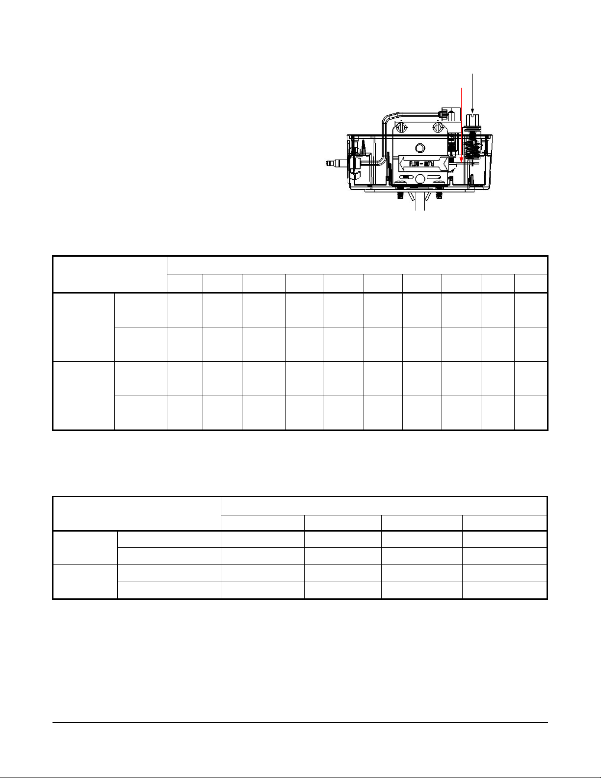
• If the lever fails to click every time when returning
Figure 11: Minimum Adjustment
Depress Main LeverHere
AdjustmentBushing(Screw)
to the original position, then the control’s flow rate
is set below the factory-set minimum value.
Turn the adjustment scr ew clockwise to raise the
flow rate required to activate the switch. See
Figure 10.
Table 3 and Table 4 show the range of flow settings
typically obtainable. These values represent inst allation
in a horizontal line with at least 10 pipe diameters of
straight pipe before and after a typical tee. The typical
tee has a 1 in. tapping (without bushing) facing up. The
F240EA switch is threaded into this tapping. Fluid is
water at 40 psi (276 kPa) pressure.
Table 3: Flow Rates for 1 in. to 3 in. Paddles
3
/hr) Required to Activate Switch for Pipe Size (in.)
1
1-1/2
7.50
(1.70)
5.00
(1.14)
19.2
(4.36)
18.0
(4.01)
Minimum
Adjustment
Maximum
Adjustment
Flow
Increase
(Close)
Flow
Decrease
(Open)
Flow
Increase
(Close)
Flow
Decrease
(Open)
1
4.20
(0.95)
2.50
(0.57)
8.80
(2.00)
8.50
(1.93)
GPM (m
1-1/4
5.80
(1.32)
3.70
(0.84)
13.3
(3.02)
12.5
(2.84)
1
2
13.7
(3.11)
9.50
(2.16)
29.0
(6.59)
27.0
(6.13)
2-1/2
18.0
(4.09)
12.5
(2.84)
34.5
(7.84)
32.0
(7.27)
2
3
27.5
(6.24)
19.0
(4.32)
53.0
(12.0)
50.0
(11.4)
3
4
65.0
(14.8)
50.0
(11.4)
128
(29.1)
122
(27.7)
3
5
125
(28.4)
101
(22.9)
245
(55.6)
235
(53.4)
3
6
190
(43.2)
158
(35.9)
375
(85.2)
360
(81.8)
3
8
375
(85.2)
320
(72.7)
760
(173)
730
(166)
1. Values for the 2 in. paddle trimmed to fit the pipe.
2. Values for the 3 in. paddle trimmed to fit the pipe.
3. Values calculated for factory-installed set of 1 in., 2 in., and 3 in. paddles.
Ta ble 4: Flow Rates for 4 in. to 8 in. Pipe Sizes with Larger Paddle
GPM (m
3
/hr) Required to Activate Switch for Pipe Size (in.)
456 8
Minimum
Adjustment
Maximum
Adjustment
Flow Increase (Close)
Flow Decrease (Open)
Flow Increase (Close)
Flow Decrease (Open)
37.0 (8.4)
27.0 (6.1)
81.0 (13.4)
76.0 (17.3)
1
1
1
1
57.0 (12.9)
(41.0 (9.3)
118.0 (26.8)
1 11.0 (25.2)
1. These GPM (m3/hr) values are for the switch with a 6 in. paddle. For 4 in. and 5 in. size pipe, trim the paddle to fit the pipe.
1
1
1
1
74.0 (16.8)
54.0 (12.3)
144.0 (32.7)
135.0 (30.7)
1
1
1
1
205.0 (46.6)
170.0 (38.6)
415.0 (94.2)
400.0 (90.8)
1
1
1
F240EA Pneumatic Liquid Flow Switch Installation Instructions
6
Page 7
Operation
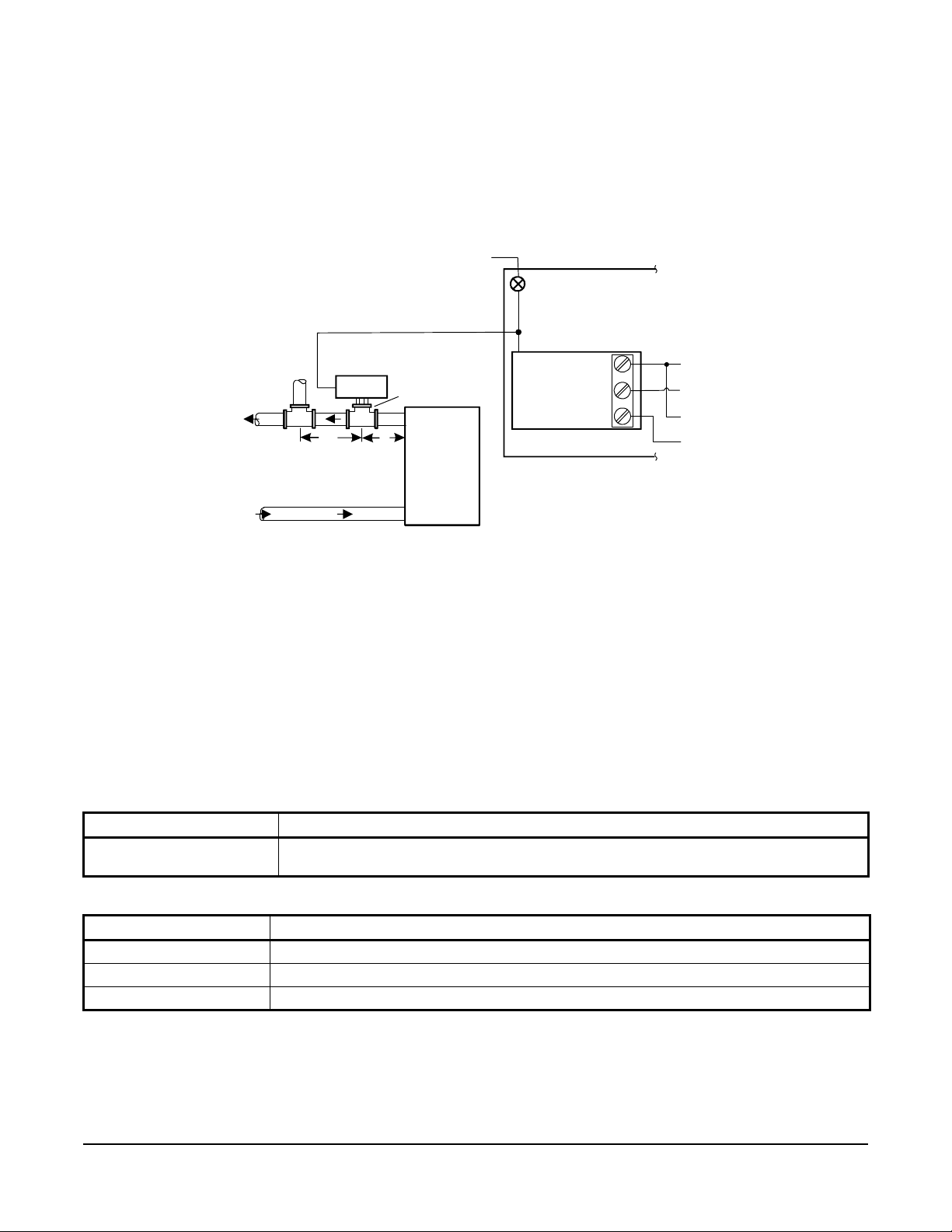
Figure 12: Typical Installation of the F240EA Pneumatic Liquid Flow Switch
BLUE (N.C.)
Remote Panel
Wire to
Circuit
Wire to
Alarm Circuit
Restrictor
20 psig (138 kPa)
Water Chiller
A
A
Chilled
Water
Supply
Chilled
Water
Dimensi on A must be at least
5 pipe diameters from the near est
elbow, valve, or other pi pe restriction.
Flow Swit ch
Tee or welded
half coup ling
FIG:F240EA_App
The flow switch responds to pressure exerted on the
paddle by the flowing liquid. The pneumatic control port
opens on flow decrease and closes on flow increase.
A range adjustment screw adjusts the rate of the flow
required to activate the switch. For flow rates, see
Table 3 and Table 4.
Supply Air
See Figure 12 for a typical installation of an F240EA
Pneumatic Liquid Flow Switch in an explosion-proof
application (or an application where it is more practical
to run a single pneumatic line instead of electrical
wiring).
P10 Pres s ur e Contr ol
Return
Checkout Procedure
Before you leave the installation, observe at least three
complete operating cycles to be sure that all
components are functioning correctly.
RED (COM)
YELLO W ( N.O.)
Repair Information
Do not make field repairs, except for replacement of
the flow paddle. For a replacement F240EA pn eumatic
fluid flow switch or paddle kit, contact the nearest
Chiller Start
Johnson Controls/PENN® distributor. For more
information, contact Johnson Controls/PENN
application engineering at 1-800-275-5676.
Ordering Information
Table 5: F240EA Pneumatic Liquid Flow Switch
Product Code Number Description
F240EA-01C Pneumatic liquid flow switch with Type 3R (NEMA) enclosure, stainless steel 3-piece paddle
(3 in., 2 in., and 1 in. segments)
Table 6: Replacement Paddle Parts
Product Code Number Description
KIT21A-600 Stainless steel 3-piece paddle (3 in., 2 in., and 1 in. segments)
KIT21A-601 Stainless steel 6 in. paddle
KIT21A-602 Stainless steel 3-piece paddle (3 in., 2 in., and 1 in. segments) and Stainless steel 6 in. paddle
F240EA Pneumatic Liquid Flow Switch Installation Instructions
7
Page 8

Johnson Controls/PENN® and Johnson Controls® are registered trademarks of Johnson Controls, Inc.
in the United States of America and/or other countries. All other trademarks used herein are the
property of their respective owners. © Copyright 2015 by Johnson Controls, Inc. All rights reserved.
Building Efficiency
507 E. Michigan Street, Milwaukee, WI 53202
Troubleshooting
Table 7: Troubleshooting
Symptom Solution
Water (condensate) appears within the
enclosure.
Fluid from the tank leaks into the enclosure
due to a rod seal failure.
Switch does not activate due to debris in
switch mechanism.
Switch action is reversed. Ensure pneumatic connections are made properly.
Switch does not function. Check the pneumatic connections.
Switch fails to return to the no-flow position. The switch may be set lower than the factory setting. Increase the setting.
Switch does not activate on flow increase. Check for a cracked or broken paddle. Replace the paddle, if necessary.
If the control has a Type 3R enclosure, inspect the grommet in the
field-installed cable gland or conduit fitting, and replace the grommet if it is
defective.
Replace the flow switch.
Clear any debris from within the switch mechanism. Test the operation of
the switch several times for proper operation.
On vertical pipes, ensure that the direction of flow is up. The arrow on the
switch enclosure must point in the direction of the flow.
Technical Specifications
F240EA Pneumatic Liquid Flow Switch
Switch Pneumatic
Ambient Operating Conditions 32 to 140°F (0 to 60°C)
1
Maximum Fluid Temperature
Maximum Fluid Pressure 290 psi (2,000 kPa)
Enclosure Type 3R (NEMA)/IP43
Paddle Stainless steel
Pipe Connector 1 in. 11-1/2 NPT Threads
Pneumatic Switch Action Closes on increasing flow, opens on decreasing flow
Tubing Connector Barb fitting for 1/4 in. O.D. plastic tubing
Shipping Weight 1.7 lb (0.8 kg)
250°F (121°C)
1. Ensure that the low liquid temperature combined with the low ambient temperature does not lead to freezing the liquid
inside the body (or bellows, where appropriate). Please observe the liquid freezing point.
The performance specifications are nominal and conform to acceptable industry standards. For application at conditions beyond these
specifications, consult Johnson Controls/PENN Refrigeration Application Engineering at 1-800-275-5676. Johnson Controls, Inc. shall not be
liable for damages resulting from misapplication or misuse of its products.
F240EA Pneumatic Liquid Flow Switch Installation Instructions
Published in U.S.A. www.johnsoncontrols.com
8
 Loading...