

Page 1
Power and Energy Meters
Code No. LIT-1900845
Issued September 2, 2014
EM-1000/-2000/-3000/-4000 Series Multifunction Power and Energy Meters
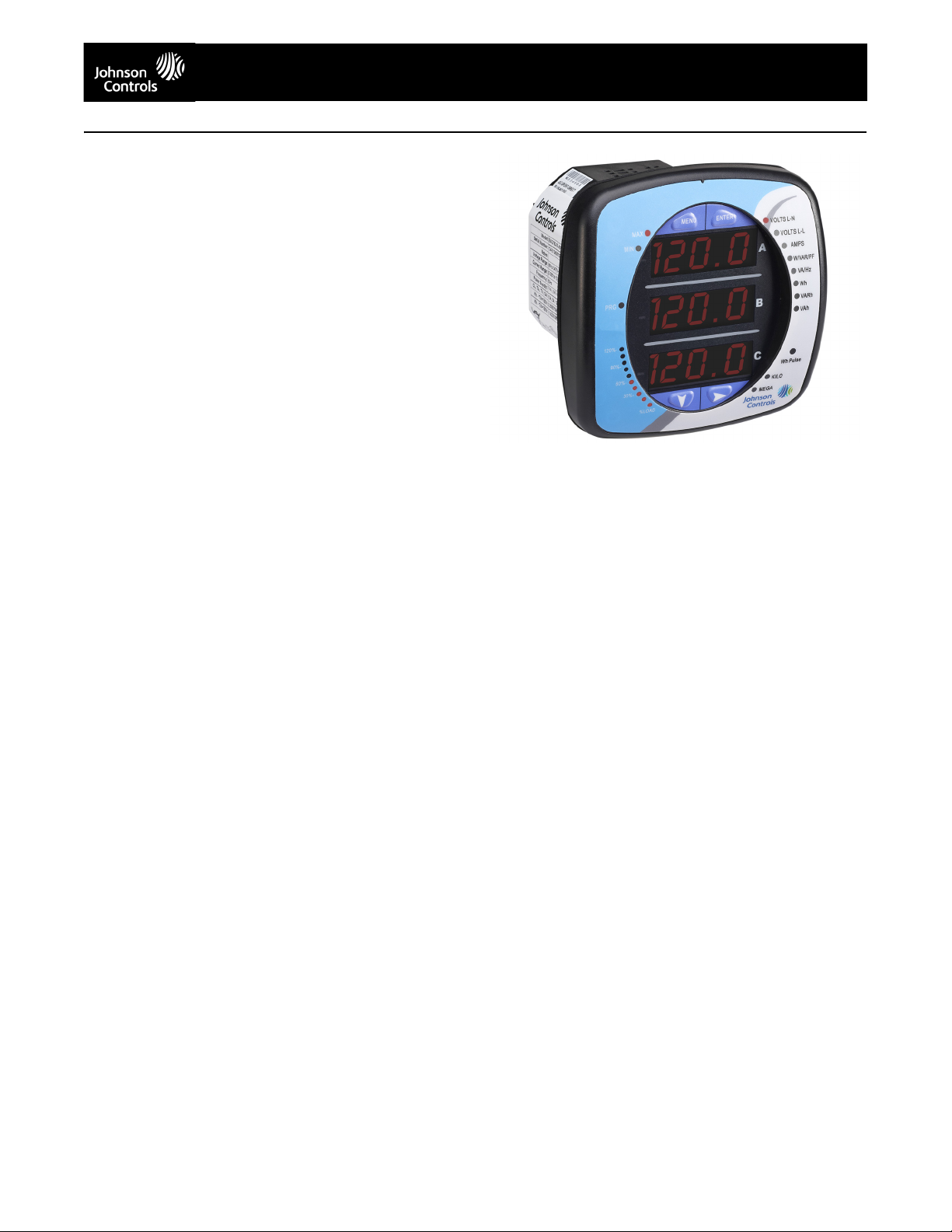
EM-1000 Series Meter Description
The EM-1000 Series monitor is an affordable multifunction power
meter designed to be used in electrical substations, panel boards
and as a power meter for OEM equipment. The unit provides
multifunction measurement of all electrical parameters. It is easy to
use and install and is perfect both for new metering applications and
as a simple replacement of existing analog meters.
The EM-1000 Series meter is designed with advanced measurement
capabilities, allowing it to achieve high performance accuracy. The
EM-1000 Series meter is specified as a 0.5% class energy meter,
meeting ANSI C12.20 (0.5%) and IEC 62053-22 (0.5%) accuracy
classes.
The EM-1000 Series meter supplies multifunction measurement
including voltage, current, power, frequency, energy, etc. For serial
communication, the EM-1000 Series meter has a combination
RS485/Pulse Com port.
The EM-1000 Series meter has an LED with 3 .56”, bright red lines
of display for easy readability.It features an anti-dither algorithm to
improve reading stability, benefitting operators. The unit utilizes high
speed DSP technology with high resolution A/D conversion to
provide stable and reliable measurements.
EM-1000 Series Meter Features
• 0.5% Class Accuracy
• Measurements Including Voltage, Current, Power, Frequency,
Energy, Etc.
• Standard RS485 with Modbus
• Large Bright Red LED Display
• % of Load Bar for Analog Meter Perception
• Fits Both ANSI and DIN Cut-outs
• Great For Retrofit and New Applications
• Uses Minimal Panel Space and Depth
• Easy-to-Use Faceplate Programming
• Phasor Diagram Showing Wiring Status
• Display Auto-Scroll Feature
• Color Coordinated Voltage and Current Inputs
®
Protocol*
Applications
• Commercial Metering
• Industrial Metering
• Power Generation
• Campus Metering
• Sub-metering
• Indication Meter Replacement
Available Models
The EM-1000 Series meter can be ordered in any of the following
models:
• B – Volts and Amps Meter – Default model
• C – Volts, Amps, kW, kVAR, PF, kVA, Freq
• D – Volts, Amps, kW, kVAR, PF, kVA, Freq, kWh, kVAh, kVARh
Advanced Communication Capability
Back Mounted Communication Port with KYZ Pulse
• RS485 – This port allows RS485 communication using Modbus
Protocol. Baud rates are from 9,600 to 57,600.
• KYZ Pulse – In addition to the RS485, this port includes a KYZ pulse
mapped to positive energy. This is a fixed energy pulse.
The performance specifications are nominal and conform to acceptable industry standards. For applications at conditions beyond these specifications, consult the local Johnson Controls office.
Johnson Controls, Inc. shall not be liable for damages resulting from misapplication or misuse of its products. © 2014 Johnson Controls, Inc.
Rugged and Safe Voltage and Current Inputs
The EM-1000 Series meter is ruggedly designed for harsh electrical
applications in both high voltage and low voltage power systems. This
is especially important in Power Generation, Utility Substation and
Critical User applications. The structural and electrical design of this
meter was developed based on the recommendations and approval of
many of our utility customers.
High Isolation Universal Voltage Inputs
Voltage inputs allow measurement of up to 416 Volts Line to Neutral
and 721 Volts Line to Line. This insures proper meter safety when
wiring directly to high voltage systems. One unit will perform to
specification on 69 Volt, 120 Volt, 230 Volt, 277 Volt and 347 Volt power
systems.
Short Circuit Safe Current Inputs
Current inputs use a unique dual input method:
• Method One – CT Lead Pass Through. The CT Lead passes directly
through the meter without any physical termination on the meter. This
insures that the meter cannot be a point of failure on the CT circuit.
This is preferable to utility users when sharing relay class CTs. No
Burden is added to the secondary CT circuit.
• Method Two – Current “Gills.” This unit additionally provides ultra rugged termination pass-through bars, allowing the CT leads to be
terminated on the meter. The EM-1000 Series meter’s stud-based
design insures that your CTs will not open in a fault condition.
ANSI and DIN Installation
The unit mounts directly in an ANSI C39.1 (4" round form) or an IEC 92
mm DIN square form. This is perfect for new installations and for
existing panels. In new installations, simply use DIN or ANSI punches.
For existing panels, pull out old analog meters and replace them with
the EM-1000 Series meter. The meter uses standard voltage and
current inputs so that CT and PT wiring does not need to be replaced.
• Perfect for switchgear panel direct retrofit
• Uses minimal panel space
• Mounts in only 4.25" panel depth
®
* Modbus® is a registered trademark of Schneider Electric, licensed to the
Modbus Organization, Inc.
EM-1000 Series Meter
www.johnsoncontrols.com
1
Page 2

EM-1000/-2000/-3000/-4000 Series Multifunction Power and Energy Meters (Continued)
Technical Specifications
EM-1000 Series Meter
Voltage Inputs 20-416 Volts Line to Neutral, 20-721 Volts Line to Line
Current Inputs Class 10: (0 to 10)A, 5 Amp Nominal, 10 Amp Maximum
Isolation All Inputs and Outputs are Galvanically Isolated to 2500 Volts AC
Environmental Rating Storage: (-20 to +70)° C
Sensing Method RMS
Update Rate All Parameters up to Every 60 Cycles
Power Supply (90 to 265) Volts AC
Communication Format RS485 Port (Through Backplate)
KYZ Pulse Typ e F or m A
Dimensions and Shipping Weight: 2 lbs/0.907 kg
Compliance IEC62053-22 (0.5% Accuracy)
Universal Voltage Input
Input Withstand Capability – Meets IEEE C37.90.1 (Surge Withstand Capability)
Programmable Voltage Range to Any PT Ratio
Supports: 3 Element WYE, 2.5 Element WYE, 2 Element Delta, 4 Wire Delta Systems
Burden: 0.014VA/Phase at 120 Volts
Input Wire Gauge Max (AWG 12 / 2.5mm2)
Fault Current Withstand (For 23° C, 3 Phase Balanced WYE or Delta load): 100 Amps for 10
Seconds, 300 Amps for 3 Seconds, 500 Amps for 1 Second
Programmable Current to any CT Ratio
Burden 0.005VA Per Phase Max at 11 Amps
Pickup Current 0.1% of Nominal
Pass Through Wire Gauge Dimension: 0.177" / 4.5mm
Continuous Current Withstand: 20 Amps for Screw Terminated or Pass Through Current
Connections
Operating: (-20 to +70)° C
Humidity: to 95% RH Non-Condensing
Faceplate Rating: NEMA12 (Water Resistant)
Sampling at 400+ Samples per Cycle on All Channels Measured Readings Simultaneously
Com Port Baud Rate: (9,600 to 57,600)
Com Port Address: 0-247
8 Bit, No Parity
RTU, ASCII
Modbus
On Resistance: 23-35 Ohm
Peak Voltage: 350 VDC
Continuous Load Current: 120mA
Peak Load Current: 350mA (10ms)
Off State Leakage Current @ 350VDC: 1mA
Basic Unit: (H4.85 x W4.85 x L4.25) in/(H12.32 x W12.32 x D10.54) cm
Mounts in Either 92mm Square DIN or ANSI C39.1 4" Round Cut-outs
Shipping Container Dimensions: 6" Cube
ANSI C12.20 (0.5% Accuracy)
ANSI (IEEE) C37.90.1 Surge Withstand
ANSI C62.41 (Burst)
EN61000-6-2 - Immunity for Industrial Environments: 2005
EN61000-6-4 - Emission Standards for Industrial Environments: 2007
EN61326-1 - EMC Requirements: 2006
UL File #E363785
UL Spec: 61010-1
The performance specifications are nominal and conform to acceptable industry standards. For applications at conditions beyond these specifications, consult the local Johnson Controls office.
Johnson Controls, Inc. shall not be liable for damages resulting from misapplication or misuse of its products. © 2014 Johnson Controls, Inc.
www.johnsoncontrols.com
2
Page 3
EM-1000/-2000/-3000/-4000 Series Multifunction Power and Energy Meters (Continued)
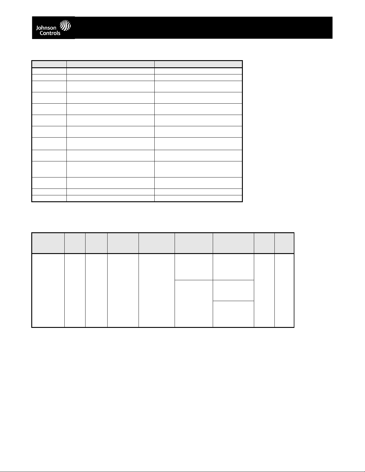
EM-1000 Series Meter Accuracy - For 23o C, 3 Phase Balanced Wye or Delta Load
Parameter Accuracy Accuracy Input Range
Voltage L-N [V] 0.2% of reading
Voltage L-L [V] 0.4% of reading (120 to 600)V
Current Phase
[A]
Current Neutral
(calculated) [A]
Active Power
Tot al [ W]
Active Energy
Tot al [ Wh ]
Reactive Power
Total [VAR]
Reactive Energy
Total [VARh
Apparent Power
Tot al [ VA]
Apparent
Energy Total
[VAh]
Power Factor 1.0% of reading
Frequency +/- 0.01Hz (45 to 65)Hz
Load Bar +/- 1 segment
0.2% of reading
2.0% of Full Scale
0.5% of reading
0.5% of reading
1.0% of reading
1.0% of reading
]
1.0% of reading
1.0% of reading
2
1
1
1,2
1,2
1,2
1,2
1,2
1,2
1,2
1
(69 to 480)V
(0.15 to 5)A
(0.15 to 5)A @ (45 to 65)Hz
(0.15 to 5)A @ (69 to 480)V @ +/- (0.5 to 1)
lag/lead PF
(0.15 to 5)A @ (69 to 480)V @ +/- (0.5 to 1)
lag/lead PF
(0.15 to 5)A @ (69 to 480)V @ +/- (0 to 0.8)
lag/lead PF
(0.15 to 5)A @ (69 to 480)V @ +/- (0 to 0.8)
lag/lead PF
(0.15 to 5)A @ (69 to 480)V @ +/- (0.5 to 1)
lag/lead PF
(0.15 to 5)A @ (69 to 480)V @ +/- (0.5 to 1)
lag/lead PF
(0.15 to 5)A @ (69 to 480)V @ +/- (0.5 to 1)
lag/lead PF
(0.005 to 6)A
1
For 2.5 element programmed units,
degrade accuracy by an additional 0.5%
of reading.
2
For unbalanced voltage inputs where at
least one crosses the 150V auto-scale
threshold (for example, 120V/120V/208V
system), degrade accuracy by additional
0.4%.
The EM-1000 Series meter’s accuracy
meets the IEC62053-22 Accuracy
Standards for 0.5% Class meters.
EM-1000 Series Meter Ordering Chart
Product-
S e r i e s
EM-1
EM-1000
Series Meter
Network
Protocol
4
Modbus
485
Freq. -Power
Supply
60
60 Hz
System
-0
90-265
VAC
Current Class -Mounting V-SwitchTM
Pack
0
5 Amp
Secondary
-A
ANSI Mounting BDefault V-Switch
Volts/
Amps
-D
DIN Mounting
C
above with
Power and Freq
D
above
with DNP 3.0 and
Energy Counters
0 0
The performance specifications are nominal and conform to acceptable industry standards. For applications at conditions beyond these specifications, consult the local Johnson Controls office.
Johnson Controls, Inc. shall not be liable for damages resulting from misapplication or misuse of its products. © 2014 Johnson Controls, Inc.
www.johnsoncontrols.com
3
Page 4
EM-1000/-2000/-3000/-4000 Series Multifunction Power and Energy Meters (Continued)
EM-2000 Series Meter Description
The EM-2000 Series monitor is a revenue grade power meter with
native BACnet/IP protocol. This meter is designed to integrate
seamlessly into existing and new building management systems
using the popular BACnet
data on voltage, current, power and energy usage throughout a
facility.
The EM-2000 Series meter’s metrology is industry recognized as
superior, providing revenue testable 0.2% Energy accuracy with
compliance to modern ANSI and IEC standards (ANSI C12.20
(0.2%) and IEC 62053-22 (0.2%) accuracy classes). The unit utilizes
advanced DSP technology, high sampling rates and 24-bit analog to
digital conversion to measure and analyze power accurately and
reliably.
The EM-2000 Series meter was designed to be the perfect device for
“Green” initiatives, LEED certified projects, smart buildings and all
kinds of smart energy projects. It has embedded RJ45 10/100BaseT
Ethernet communication that supplies an embedded Web server,
that lets you view energy usage through any standard browser. By
letting you track energy use and power quality from wherever you
are, the meter gives you the information you need to accurately
identify cost-saving measures and respond to power quality
problems when they arise.
EM-2000 Series Meter Features
• Multifunction Measurements of AC Voltage, Current, Frequency,
Power and Energy
• Industry Recognized Superior 0.2% Energy Class Accuracy
• BACnet/IP 100BaseT Ethernet Protocol
• Highly Reliable Industrial Rated Design
• Utility Block and Rolling Average Demand
• Adjustable Demand Profiles
• Max and Min Available on Most Other Parameters
• Voltage Provides Instantaneous Max and Min for Surge and Sag
Limits
Applications
• LEED Projects
• Smart Buildings
• Commercial Energy Management
• HVAC Efficiency Monitoring
• Building Management Systems
EM-2000 Series Meter’s BACnet/IP Through the
Web
The EM-2000 Series meter’s BACnet/IP comes standard with a Web
interface. Use the BACnet/IP
BACnet/IP
with any standard Web browser. You do not need to be on-site - you
can check on your buildings from anywhere in the world! There is
also a Modbus
Modbus
configuration and track energy usage through the Internet
TCP Socket that can be used to simultaneously poll
TCP through the same device.
Traceable Watt-Hour Test Pulse for Accuracy
Verification
The EM-2000 Series meter is a traceable revenue meter. It contains
a utility grade test pulse allowing power providers to verify and
confirm that the meter is performing to its rated accuracy. This is an
essential feature required of all billing grade meters.
The performance specifications are nominal and conform to acceptable industry standards. For applications at conditions beyond these specifications, consult the local Johnson Controls office.
Johnson Controls, Inc. shall not be liable for damages resulting from misapplication or misuse of its products. © 2014 Johnson Controls, Inc.
®
protocol. The unit allows users to gather
Interface to remotely set up the
EM-2000 Series Meter
Rugged and Safe Voltage and Current Inputs
The EM-2000 Series meter is ruggedly designed for harsh electrical
applications in both high voltage and low voltage power systems. This
is especially important in Power Generation, Utility Substation and
Critical User applications. The structural and electrical design of this
meter was developed based on the recommendations and approval of
many of our utility customers.
High Isolation Universal Voltage Inputs
Voltage inputs allow measurement of up to 416 Volts Line to Neutral
and 721 Volts Line to Line. This insures proper meter safety when
wiring directly to high voltage systems. One unit will perform to
specification on 69 Volt, 120 Volt, 230 Volt, 277 Volt and 347 Volt power
systems.
Short Circuit Safe Current Inputs
Current inputs use a unique dual input method:
• Method One – CT Lead Pass Through. The CT Lead passes directly
through the meter without any physical termination on the meter. This
insures that the meter cannot be a point of failure on the CT circuit.
This is preferable to utility users when sharing relay class CTs. No
Burden is added to the secondary CT circuit.
• Method Two – Current “Gills.” This unit additionally provides ultra rugged termination pass-through bars, allowing the CT leads to be
terminated on the meter. The EM-2000 Series meter’s stud-based
design insures that your CTs will not open in a fault condition.
IrDA Port
The EM-2000 Series meter has an IrDA port on its faceplate, for remote
interrogation by an IrDA-equipped laptop PC.
ANSI and DIN Installation
The unit mounts directly in an ANSI C39.1 (4" round form) or an IEC 92
mm DIN square form. This is perfect for new installations and for
existing panels. In new installations, simply use DIN or ANSI punches.
For existing panels, pull out old analog meters and replace them with
the EM-2000 Series meter. The meter uses standard voltage and
current inputs so that CT and PT wiring does not need to be replaced.
• Perfect for switchgear panel direct retrofit
• Uses minimal panel space
• Mounts in only 4.25" panel depth
www.johnsoncontrols.com
4
Page 5

EM-1000/-2000/-3000/-4000 Series Multifunction Power and Energy Meters (Continued)
Technical Specifications
EM-2000 Series Meter
Voltage Inputs 20-416 Volts Line to Neutral, 20-721 Volts Line to Line
Current Inputs Class 10: (0 to 10)A, 5 Amp Nominal, 10 Amp Maximum; Class 2: (0 to 2)A, 1 Amp Nominal,
Isolation All Inputs and Outputs are Galvanically Isolated to 2500 Volts AC
Environmental Rating Storage: (-20 to +70)° C
Sensing Method RMS
Update Rate Watt, VAR, and VA- Every 6 Cycles; All Other Parameters - Every 60 Cycles
Power Supply (90 to 265) Volts AC / (100 to 370) Volts DC
Communication Format BACnet/IP
KYZ Pulse Typ e F or m A
Dimensions and Shipping Weight: 2 lbs/0.907 kg
Compliance IEC62053-22 (0.2% Accuracy)
Universal Voltage Input
Input Withstand Capability – Meets IEEE C37.90.1 (Surge Withstand Capability)
Programmable Voltage Range to Any PT Ratio
Supports: 3 Element WYE, 2.5 Element WYE, 2 Element Delta, 4 Wire Delta Systems
Burden: 0.36VA/Phase Max at 600 Volts; 0.014VA/Phase at 120 Volts
Input Wire Gauge Max (AWG 12 / 2.5mm2)
Secondary
Fault Current Withstand (For 23° C, 3 Phase Balanced WYE or Delta load): 100 Amps for 10
Seconds, 300 Amps for 3 Seconds, 500 Amps for 1 Second
Programmable Current to any CT Ratio
Burden 0.005VA Per Phase Max at 11 Amps
Pickup Current 0.1% of Nominal
Pass Through Wire Gauge Dimension: 0.177" / 4.5mm
Continuous Current Withstand: 20 Amps for Screw Terminated or Pass Through Current
Connections
Operating: (-20 to +70)° C
Humidity: to 95% RH Non-Condensing
Faceplate Rating: NEMA12 (Water Resistant)
Sampling at 400+ Samples per Cycle on All Channels Measured Readings Simultaneously
(18- to 60) Volts DC optional power supply
IrDA (Through Faceplate)
Modbus TCP
On Resistance: 23-35 Ohm
Peak Voltage: 350 VDC
Continuous Load Current: 120mA
Peak Load Current: 350mA (10ms)
Off State Leakage Current @ 350VDC: 1mA
Opto-Isolation: 3750V (6 0Hz, 1min)
Basic Unit: (H4.85 x W4.85 x L4.25) in/(H12.32 x W12.32 x D10.54) cm
Mounts in Either 92mm Square DIN or ANSI C39.1 4" Round Cut-outs
Shipping Container Dimensions: 6" Cube
ANSI C12.20 (0.2% Accuracy)
ANSI (IEEE) C37.90.1 Surge Withstand
ANSI C62.41 (Burst)
EN61000-6-2 - Immunity for Industrial Environments: 2005
EN61000-6-4 - Emission Standards for Industrial Environments: 2007
EN61326-1 - EMC Requirements: 2006
UL File #E363785
UL Spec: 61010-1
Ethernet (Through Backplate)
The performance specifications are nominal and conform to acceptable industry standards. For applications at conditions beyond these specifications, consult the local Johnson Controls office.
Johnson Controls, Inc. shall not be liable for damages resulting from misapplication or misuse of its products. © 2014 Johnson Controls, Inc.
www.johnsoncontrols.com
5
Page 6

EM-1000/-2000/-3000/-4000 Series Multifunction Power and Energy Meters (Continued)
EM-2000 Serial Meter Accuracy - For 23o C, 3 Phase Balanced Wye or Delta Load
Parameter Accuracy Accuracy Input Range
Voltage L-N [V] 0.1% of reading
Voltage L-L [V] 0.1% of reading (120 to 600)V
Current Phase
[A]
Current Neutral
(calculated) [A]
Active Power
Total [W ]
Active Energy
Total [W h]
Reactive Power
Total [VAR]
Reactive Energy
Total [VARh]
Apparent Power
Total [VA ]
Apparent
Energy Total
[VAh]
Power Factor 0.2% of reading
Frequency +/- 0.01Hz (45 to 65)Hz
Load Bar +/- 1 segment
0.1% of reading
2.0% of Full Scale
0.2% of reading
0.2% of reading
0.2% of reading
0.2% of reading
0.2% of reading
0.2% of reading
2
1
1
1,2
1,2
1,2
1,2
1,2
1,2
1,2
1
(69 to 480)V
(0.15 to 5)A
(0.15 to 5)A @ (45 to 65)Hz
(0.15 to 5)A @ (69 to 480)V @ +/- (0.5 to 1)
lag/lead PF
(0.15 to 5)A @ (69 to 480)V @ +/- (0.5 to 1)
lag/lead PF
(0.15 to 5)A @ (69 to 480)V @ +/- (0 to 0.8)
lag/lead PF
(0.15 to 5)A @ (69 to 480)V @ +/- (0 to 0.8)
lag/lead PF
(0.15 to 5)A @ (69 to 480)V @ +/- (0.5 to 1)
lag/lead PF
(0.15 to 5)A @ (69 to 480)V @ +/- (0.5 to 1)
lag/lead PF
(0.15 to 5)A @ (69 to 480)V @ +/- (0.5 to 1)
lag/lead PF
(0.005 to 6)A
1
For 2.5 element programmed units,
degrade accuracy by an additional 0.5%
of reading.
- For 1A (Class 2) Nominal, degrade
accuracy by an additional 0.5% of
reading.
- For 1A (Class 2) Nominal, the input
current range for Accuracy specification
is 20% of the values listed in the table.
2
For unbalanced voltage inputs where at
least one crosses the 150V auto-scale
threshold (for example, 120V/120V/208V
system), degrade accuracy by additional
0.4%.
EM-2000 Series Meter Ordering Chart
Product-
S e r i e s
EM-2
EM-2000
Series Meter
Network
Protocol
7
BACnet/
IP
Freq. -Power
Supply
50
5 0 H z
System
90-265
VAC/100-
VDC
60
60 Hz
System
18-60
VDC
-0
370
-1
Current Class -Mounting V-Switch
Pack
5
5 Amp
Secondary
1
1 Amp
-A
ANSI Mounting 0Default V-Switch
Volts/
Amps
-D
DIN Mounting
Secondary
0 0
The performance specifications are nominal and conform to acceptable industry standards. For applications at conditions beyond these specifications, consult the local Johnson Controls office.
Johnson Controls, Inc. shall not be liable for damages resulting from misapplication or misuse of its products. © 2014 Johnson Controls, Inc.
www.johnsoncontrols.com
6
Page 7

EM-1000/-2000/-3000/-4000 Series Multifunction Power and Energy Meters (Continued)
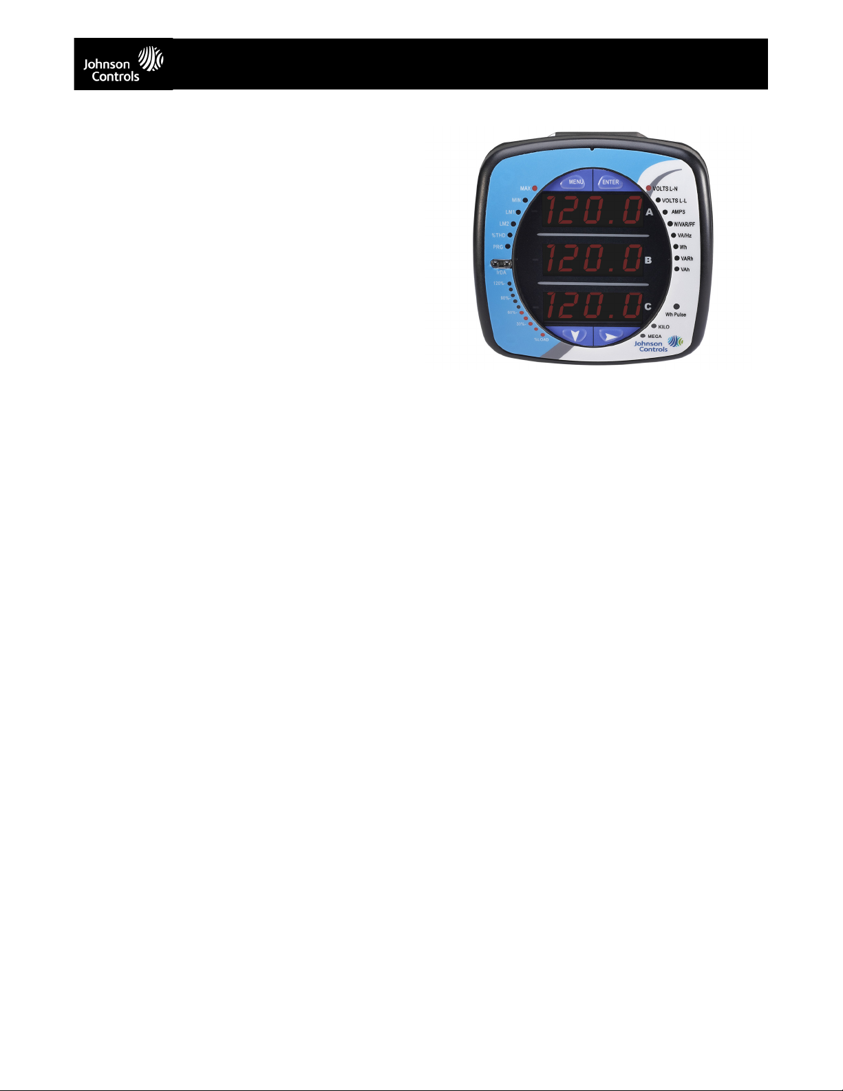
EM-3000 Series Meter Description
The EM-3000 Series meter is a high performance product designed
to measure revenue grade electrical energy usage and communicate
back that information using modern communication media. The unit
supports RJ45 Ethernet or IEEE 802.11 WiFi Ethernet connections.
This allows it to be placed anywhere within a facility and have it
communicate back to central software quickly and automatically. The
unit also has a front IrDA port that can be read and configured with
an IrDA-equipped device, such as a laptop PC.
The unit is designed with advanced measurement capabilities,
allowing it to achieve high performance accuracy. The EM-3000
Series meter is specified as a 0.2% class energy meter for billing
applications.
The EM-3000 Series meter uses standard 5 or 1 Amp CTs (either
split or donut). It surface mounts to any wall and is easily
programmed in minutes. The unit is designed specifically to be a low
cost, highly accurate sub-meter with advanced communication and
easy installation.
EM-3000 Series Meter Features
• 0.2% Class Revenue Certifiable Energy and Demand Sub-meter
• Meets ANSI C12.20 (0.2%) and IEC 62053-22 (0.2%) Classes
• Multifunction Measurement Capability
• Bright Red LED Display with three .56" lines
• % of Load Bar for Analog Meter Perception
• Ethernet or Wireless Ethernet via Modbus TCP
• Direct Interface with Most Building Management Systems
• Very Easy To Install - Small Footprint
Applications
• Universities
• Commercial Buildings
• Shopping Malls
• Airports
• Industrial Sub-metering
• Government Facilities
• Military
• Energy Efficiency OEMs
Available Models
The EM-3000 Series meter can be ordered in either of the following
models:
• E – Volts and Amps Meter with Energy Counters– Default model
• F – Volts and Amps Meter with Energy Counters, and Harmonics
and Limits
WiFi or Land Based Ethernet
The EM-3000 Series meter gives you two Ethernet options — either
an RJ45 wired, or a WiFi connection. Both connections are easily
configurable using Telnet. The sub-meter communicates over any
existing wireless or wired Ethernet infrastructure. Just install the unit,
plug in its IP address, and the device automatically connects to your
LAN.
The WiFi option allows the EM-3000 Series meter to be used on
standard WiFi base stations, providing a simple, over-the-counter
wireless architecture. You can extend the network simply by adding
WiFi access points. Wireless Ethernet is reliable and easy to
integrate, making it the superior solution for mass meter deployment.
The performance specifications are nominal and conform to acceptable industry standards. For applications at conditions beyond these specifications, consult the local Johnson Controls office.
Johnson Controls, Inc. shall not be liable for damages resulting from misapplication or misuse of its products. © 2014 Johnson Controls, Inc.
Benefits of WiFi Over Dedicated Radio
• Standard Infrastructure - No Dedicated Hardware
• Low Cost to Deploy and Expand
• Superior Speed over Dedicated Wireless Networks
• Significantly Easier to Configure and Maintain
• Secure Connection - WEP, WPA, or WPA2 Wireless Security
• Standard Modbus
• Can Be Easily Integrated through Internet
IrDA Port
The EM-3000 Series meter has an IrDA port on its faceplate, for remote
interrogation by an IrDA-equipped laptop PC.
Traceable Watt-Hour Test Pulse for Accuracy
Verification
The EM-3000 Series meter is a traceable revenue meter. It contains a
utility grade test pulse allowing power providers to verify and confirm
that the meter is performing to its rated accuracy. This is an essential
feature required of all billing grade meters.
KYZ Pulse
For applications in which a pulse is needed, the unit also provides a
KYZ output which pulses proportional to the amount of energy
consumed. This feature is used for pulse counting applications or for
building management systems where serial or Ethernet protocol is not
available.
Utility Peak Demand Metering
The EM-3000 Series meter provides user-configured Block Window or
Rolling Window Demand. This allows you to set up a particular utility
demand profile. Block Window Demand is demand used over a fixed
user-configured demand period (usually 5, 15 or 30 minutes). Rolling
Window Demand is a fixed window demand that moves for a user
specified sub-interval period. An example is a 15-minute demand using
3 subintervals, providing a new demand reading every 5 minutes based
on the last 15 minutes. Readings for kW, kVAR, kVA and PF are
calculated using utility demand structures. Other parameters offer max
and min capability over the user-selectable averaging period. Voltage
provides a non-rolling instantaneous max and min reading, displaying
the highest surge and lowest sag seen by the meter.
EM-3000 Series Meter
®
TCP Data Stream
www.johnsoncontrols.com
7
Page 8

EM-1000/-2000/-3000/-4000 Series Multifunction Power and Energy Meters (Continued)
Technical Specifications
EM-3000 Series Meter
Voltage Inputs 20-416 Volts Line to Neutral, 0-721 Volts Line to Line
Current Inputs Class 10: (0 to 10)A, 5 Amp Nominal,10 Amp Maximum; Class 2: (0 to 2)A, 1 Amp Nominal,
Isolation All Inputs and Outputs are Galvanically Isolated to 2500 Volts AC
Environmental Rating Storage: (-20 to +70)° C
Sensing Method RMS
Update Rate Watt, VAR, and VA- Every 6 Cycles; All Other Parameters - Every 60 Cycles
Power Supply (90 to 400) Volts AC / (100 to 370) Volts DC
Communication Format 10/100BaseTEthernet or 802.11b WiFi
Dimensions Basic Unit: (H7.9 x W7.6 x D3.2) in/(H20.07 x W19.30 x D8.13) cm
Compliance IEC62053-22 (0.2% Accuracy)
Universal Voltage Input
Input Withstand Capability – Meets IEEE C37.90.1 (Surge Withstand Capability)
Programmable Voltage Range to Any PT Ratio
Supports: 3 Element WYE, 2.5
Element WYE, 2 Element Delta, 4 Wire Delta Systems
Burden: 0.36VA/Phase Max at 600 Volts; 0.014VA/Phase at 120 Volts
Input Wire Gauge AWG #16-26
Secondary
Fault Current Withstand (For 23° C, 3 Phase Balanced WYE or Delta load): 100 Amps for 10
Seconds
Programmable Current to any CT Ratio
Burden 0.005VA Per Phase Max at 11 Amps
Pickup Current 0.1% of Nominal
Operating: (-20 to +70)° C
Humidity: to 95% RH Non-Condensing
Faceplate Rating: NEMA12 (Water Resistant)
Sampling at 400+ Samples per Cycle on All Channels Measured Readings Simultaneously
Harmonic %THD (% of Total Harmonic Distortion)
Burden 16VA Max
IrDA (Through Faceplate)
TCP
Modbus
9,600 to 57,600 Baud Rate
Com Port Address 0-247
Weight: 4 lbs/1.81 kg
ANSI C12.20 (0.2% Accuracy)
ANSI (IEEE) C37.90.1 Surge Withstand
ANSI C62.41 (Burst)
EN61000-6-2 - Immunity for Industrial Environments: 2005
EN61000-6-4 - Emission Standards for Industrial Environments: 2007
EN61326-1 - EMC Requirements: 2006
UL File #E363785
UL Spec: 61010-1
FCC Part 15, Subpart B
The performance specifications are nominal and conform to acceptable industry standards. For applications at conditions beyond these specifications, consult the local Johnson Controls office.
Johnson Controls, Inc. shall not be liable for damages resulting from misapplication or misuse of its products. © 2014 Johnson Controls, Inc.
www.johnsoncontrols.com
8
Page 9

EM-1000/-2000/-3000/-4000 Series Multifunction Power and Energy Meters (Continued)
EM-3000 Series Meter Accuracy - For 23o C, 3 Phase Balanced Wye or Delta Load
Parameter Accuracy Accuracy Input Range
Voltage L-N [V] 0.1% of reading
Voltage L-L [V] 0.1% of reading (120 to 600)V
Current Phase
[A]
Current Neutral
(calculated) [A]
Active Power
Total [W ]
Active Energy
Total [W h]
Reactive Power
Total [VAR]
Reactive Energy
Total [VARh]
Apparent Power
Total [VA ]
Apparent
Energy Total
[VAh]
Power Factor 0.2% of reading
Frequency +/- 0.01Hz (45 to 65)Hz
Total Harmonic
Distortion
Load Bar +/- 1 segment
0.1% of reading
2.0% of Full Scale
0.2% of reading
0.2% of reading
0.2% of reading
0.2% of reading
0.2% of reading
0.2% of reading
1
5.0%
2
1
1
1,2
1,2
1,2
1,2
1,2
1,2
1,2
1
(69 to 480)V
(0.15 to 5)A
(0.15 to 5)A @ (45 to 65)Hz
(0.15 to 5)A @ (69 to 480)V @ +/- (0.5 to 1)
lag/lead PF
(0.15 to 5)A @ (69 to 480)V @ +/- (0.5 to 1)
lag/lead PF
(0.15 to 5)A @ (69 to 480)V @ +/- (0 to 0.8)
lag/lead PF
(0.15 to 5)A @ (69 to 480)V @ +/- (0 to 0.8)
lag/lead PF
(0.15 to 5)A @ (69 to 480)V @ +/- (0.5 to 1)
lag/lead PF
(0.15 to 5)A @ (69 to 480)V @ +/- (0.5 to 1)
lag/lead PF
(0.15 to 5)A @ (69 to 480)V @ +/- (0.5 to 1)
lag/lead PF
(0.5 to 10)A or (69 to 480)V, measurement
range (1 to 99.99)%
(0.005 to 6)A
1
For 2.5 element programmed units,
degrade accuracy by an additional 0.5%
of reading.
- For 1A (Class 2) Nominal, degrade
accuracy by an additional 0.5% of
reading.
- For 1A (Class 2) Nominal, the input
current range for Accuracy specification
is 20% of the values listed in the table.
2
For unbalanced voltage inputs where at
least one crosses the 150V auto-scale
threshold (for example, 120V/120V/208V
system), degrade accuracy by additional
0.4%.
EM-3000 Series Meter Ordering Chart
Product-
S e r i e s
EM-3
EM-3000
Series Meter
Network
Protocol
8
WiFi
Freq. -Power
Supply
50
5 0 H z
System
90-400
VAC/100-
VDC
60
60 Hz
System
370
-0
Current Class -Mounting V-Switch
Pack
5
5 Amp
Sec on da ry
-W
Default
E
Default V-Switch
Volts/
Amps, Energy
Counters
1
1 Amp
Secondary
F
above with
Harmonics and
Limits
0 0
Refer to the EM-1000/EM-2000 Series Meters’ Installation and Operation Manual (LIT-12011867) and the EM-3000 Series Meter Installation
and Operation Manual (LIT-12011874) for important product application information.
The performance specifications are nominal and conform to acceptable industry standards. For applications at conditions beyond these specifications, consult the local Johnson Controls office.
Johnson Controls, Inc. shall not be liable for damages resulting from misapplication or misuse of its products. © 2014 Johnson Controls, Inc.
www.johnsoncontrols.com
9
Page 10

EM-1000/-2000/-3000/-4000 Series Multifunction Power and Energy Meters (Continued)
EM-4000 Series Meter
EM-4000 Series Meter Description
The EM-4000 Series monitor is a multifunction data-logging power and
energy meter designed to be used in electrical substations, panel
boards, as a power meter for OEM equipment, and as a primary
revenue meter due to its high performance measurement capability.
The unit provides multifunction measurement of all electrical
parameters. It is easy to use and install and is perfect both for new
metering applications and as a simple replacement of existing analog
meters.
The EM-4000 Series meter is designed with advanced measurement
capabilities, allowing it to achieve high performance accuracy. The EM4000 Series meter is specified as a 0.2% class energy meter, meeting
ANSI C12.20 (0.2%) and IEC 62053-22 (0.2%) accuracy classes.
The EM-4000 Series meter supplies 2 Megabytes of Flash memory for
data-logging and load profiling for historical analysis. For
communication, the EM-4000 Series meter has a front panel IrDA port
and a back panel combination RS485/Pulse Com port.
The EM-4000 Series meter has an LED with 3 .56”, bright red lines of
display for easy readability.It features an anti-dither algorithm to
improve reading stability, benefitting operators. The unit utilizes high
speed DSP technology with high resolution A/D conversion to provide
stable and reliable measurements.
EM-4000 Series Meter Features
• 0.2% Class Revenue Certifiable Energy and Demand Metering
• Multifunction Measurement Including Voltage, Current, Power,
Frequency, Energy, Etc.
• Standard RS485 with Modbus
• 2MegaBytes of Flash Memory for Data-logging
• % of Load Bar for Analog Meter Perception
• Fits Both ANSI and DIN Cut-outs
• 0.001 Hz Frequency Measurement for Generating Stations
• Uses Minimal Panel Space and Depth
• Easy-to-Use Faceplate Programming
• Phasor Diagram Showing Wiring Status
• IrDA Port Enables Laptop PC Reading and Programming
• Color Coordinated Voltage and Current Inputs
®
Protocol
Applications
• Utility Metering
• Substations
• Power Generation
• Industrial Metering
• Commercial Metering
• Campus Metering
• Submetering
• Analog Meter Replacement
• Voltage Recording
Advanced Communication Capability
Back Mounted Communication Port with KYZ Pulse
• RS485 – This port allows RS485 communication using Modbus
Protocol. Baud rates are from 9,600 to 57,600.
• KYZ Pulse – In addition to the RS485, this port includes a KYZ pulse
mapped to positive energy. This is a fixed energy pulse.
®
Rugged and Safe Voltage and Current Inputs
The EM-4000 Series meter is ruggedly designed for harsh electrical
applications in both high voltage and low voltage power systems. This
is especially important in Power Generation, Utility Substation and
Critical User applications. The structural and electrical design of this
meter was developed based on the recommendations and approval of
many of our utility customers.
High Isolation Universal Voltage Inputs
Voltage inputs allow measurement of up to 576 Volts Line to Neutral
and 721 Volts Line to Line. This insures proper meter safety when
wiring directly to high voltage systems. One unit will perform to
specification on 69 Volt, 120 Volt, 230 Volt, 277 Volt and 347 Volt power
systems.
Short Circuit Safe Current Inputs
Current inputs use a unique dual input method:
• Method One – CT Lead Pass Through. The CT Lead passes directly
through the meter without any physical termination on the meter. This
insures that the meter cannot be a point of failure on the CT circuit.
This is preferable to utility users when sharing relay class CTs. No
Burden is added to the secondary CT circuit.
• Method Two – Current “Gills.” This unit additionally provides ultra rugged termination pass-through bars, allowing the CT leads to be
terminated on the meter. The EM-4000 Series meter’s stud-based
design insures that your CTs will not open in a fault condition.
ANSI and DIN Installation
The unit mounts directly in an ANSI C39.1 (4" round form) or an IEC 92
mm DIN square form. This is perfect for new installations and for
existing panels. In new installations, simply use DIN or ANSI punches.
For existing panels, pull out old analog meters and replace them with
the EM-4000 Series meter. The meter uses standard voltage and
current inputs so that CT and PT wiring does not need to be replaced.
• Perfect for switchgear panel direct retrofit
• Uses minimal panel space
• Mounts in only 4.25" panel depth
The performance specifications are nominal and conform to acceptable industry standards. For applications at conditions beyond these specifications, consult the local Johnson Controls office.
Johnson Controls, Inc. shall not be liable for damages resulting from misapplication or misuse of its products. © 2014 Johnson Controls, Inc.
www.johnsoncontrols.com
10
Page 11

EM-1000/-2000/-3000/-4000 Series Multifunction Power and Energy Meters (Continued)
Technical Specifications
EM-4000 Series Meter
Voltage Inputs 20-576 Volts Line to Neutral, 0-721 Volts Line to Line
Current Inputs Class 10: (0 to 10)A, 5 Amp Nominal, 10 Amp Maximum
Isolation All Inputs and Outputs are Galvanically Isolated to 2500 Volts AC
Environmental Rating Storage: (-20 to +70)° C
Sensing Method RMS
Update Rate Watt, VAR, and VA- Every 6 Cycles; All Other Parameters - Every 60 Cycles
Power Supply (90 to 265) Volts AC / (100 to 370) Volts DC
Communication Format RS485 Modbus
KYZ Pulse Type Form A
Dimensions and Shipping Weight: 2 lbs/0.907 kg
Compliance IEC62053-22 (0.2% Accuracy)
Universal Voltage Input
Input Withstand Capability – Meets IEEE C37.90.1 (Surge Withstand Capability)
Programmable Voltage Range to Any PT Ratio
Supports: 3 Element WYE, 2.5 Element WYE, 2 Element Delta, 4 Wire Delta Systems
Burden: 0.36VA/Phase Max at 600 Volts; 0.014VA/Phase at 120 Volts
Input Wire Gauge Max (AWG 12 / 2.5mm2)
Fault Current Withstand (For 23° C, 3 Phase Balanced WYE or Delta load): 100 Amps for 10
Seconds, 300 Amps for 3 Seconds, 500 Amps for 1 Second
Programmable Current to any CT Ratio
Burden 0.005VA Per Phase Max at 11 Amps
Pickup Current 0.1% of Nominal
Pass Through Wire Gauge Dimension: 0.177" / 4.5mm
Continuous Current Withstand: 20 Amps for Screw Terminated or Pass Through Current
Connections
Operating: (-20 to +70)° C
Humidity: to 95% RH Non-Condensing
Faceplate Rating: NEMA12 (Water Resistant)
Sampling at 400+ Samples per Cycle on All Channels Measured Readings Simultaneously
®
IrDA (Through Faceplate)
Com Port Baud Rate: (1,200 to 57,600bps)
Com Port Address: 0-247
®
Modbus
On Resistance: 23-35 Ohm
Peak Voltage: 350 VDC
Continuous Load Current: 120mA
Peak Load Current: 350mA (10ms)
Off State Leakage Current @ 350VDC: 1mA
Opto-Isolation: 3750V (6 0Hz, 1min)
Basic Unit: (H4.85 x W4.85 x L4.25) in/(H12.32 x W12.32 x D10.54) cm
Mounts in Either 92mm Square DIN or ANSI C39.1 4" Round Cut-outs
Shipping Container Dimensions: 6" Cube
ANSI C12.20 (0.2% Accuracy)
ANSI (IEEE) C37.90.1 Surge Withstand
ANSI C62.41 (Burst)
EN61000-6-2 - Immunity for Industrial Environments: 2005
EN61000-6-4 - Emission Standards for Industrial Environments: 2007
EN61326-1 - EMC Requirements: 2006
UL File #E363785
UL Spec: 61010-1
(Through Backplate)
RTU, ASCII
The performance specifications are nominal and conform to acceptable industry standards. For applications at conditions beyond these specifications, consult the local Johnson Controls office.
Johnson Controls, Inc. shall not be liable for damages resulting from misapplication or misuse of its products. © 2014 Johnson Controls, Inc.
www.johnsoncontrols.com
11
Page 12

EM-1000/-2000/-3000/-4000 Series Multifunction Power and Energy Meters (Continued)
EM-4000 Serial Meter Accuracy - For 23o C, 3 Phase Balanced Wye or Delta Load
Parameter Accuracy Accuracy Input Range
Vol ta ge L-N [V ] 0.1% of reading
Voltage L-L [V] 0.2% of reading (120 to 600)V
Current Phase
[A]
Current Neutral
(calculated) [A]
Active Power
Tot al [ W]
Active Energy
Tot al [ Wh ]
Reactive Power
Total [VAR]
Reactive Energy
Total [VARh]
Apparent Power
Tot al [ VA]
Apparent
Energy Total
[VAh]
Power Factor 0.2% of reading
Frequency +/- 0.001Hz (45 to 65)Hz
Load Bar +/- 1 segment
0.1% of reading
2.0% of Full Scale
0.2% of reading
0.2% of reading
0.2% of reading
0.2% of reading
0.2% of reading
0.2% of reading
2
1
1
1,2
1,2
1,2
1,2
1,2
1,2
1,2
1
(69 to 480)V
(0.15 to 5)A
(0.15 to 5)A @ (45 to 65)Hz
(0.15 to 5)A @ (69 to 480)V @ +/- (0.5 to 1)
lag/lead PF
(0.15 to 5)A @ (69 to 480)V @ +/- (0.5 to 1)
lag/lead PF
(0.15 to 5)A @ (69 to 480)V @ +/- (0 to 0.8)
lag/lead PF
(0.15 to 5)A @ (69 to 480)V @ +/- (0 to 0.8)
lag/lead PF
(0.15 to 5)A @ (69 to 480)V @ +/- (0.5 to 1)
lag/lead PF
(0.15 to 5)A @ (69 to 480)V @ +/- (0.5 to 1)
lag/lead PF
(0.15 to 5)A @ (69 to 480)V @ +/- (0.5 to 1)
lag/lead PF
(0.005 to 6)A
EM-4000 Series Meters Ordering Chart
Product-Series Network
Protocol
EM-4
EM-4000 Series
Meter
4
Modbus
Freq. -Power Supply Current Class -Mounting 0 0
50
50 Hz
S y s t e m
60
60 Hz
System
90-265 VAC/
100-370VDC
-0
5
5 Amp
Secondary
-AI
ANSI Mounting
-DI
DIN Mounting
The performance specifications are nominal and conform to acceptable industry standards. For applications at conditions beyond these specifications, consult the local Johnson Controls office.
Johnson Controls, Inc. shall not be liable for damages resulting from misapplication or misuse of its products. © 2014 Johnson Controls, Inc.
www.johnsoncontrols.com
12
Page 13

EM-1000/-2000/-3000/-4000 Series Multifunction Power and Energy Meters (Continued)
EM-1000/-2000/-3000/-4000 Series Meters Accessories Ordering Chart
Product Code Number Description
UNICOM 2500 RS485 to RS232 converter
UNICOM 2500-F RS485 to RS232 or fiber converter
E145350 2-wire to 4-wire RS485 cable, 6 ft long, for use with Unicom 2500/2500F
EI-1SP-100-00 100/5A split core CT with 0.84 x 2.0 in. window
EI-1SP-200-00 200/5A split core CT with 0.84 x 2.0 in. window
EI-WC4-400-RA05 400/5A split core CT with 1.3 x 1.7 in. window
EI-615-401 400/5A split core CT with 1.3 x 1.6 in. window
EI-3SP-600-00 600/5A split core CT with 2.19 x 3.25 in. window
EI-5SP-1200-00 1200/5A split core CT with 2.88 x 4.25 in. window
EI-7SP-1600-00 1600/5A split core CT with 2.88 x 6.25 in. window
EI-91SP-2000-00 2000/5A split core CT with 4.00 x 7.50 in. window
EI-91SP-3000-00 3000/5A split core CT with 4.00 x 7.50 in. window
EI-91SP-4000-00 4000/5A split core CT with 4.00 x 7.50 in. window
EI-2SFT-500 50/5A solid core CT with 1.13 ft ID with terminals and feet
EI-2SFT-101 100/5A solid core CT with 1.13 ft ID with terminals and feet
EI-2SFT-201 200/5A solid core CT with 1.13 ft ID with terminals and feet
EI-5SFT-401 400/5A solid core CT with 1.56 ft ID with terminals and feet
EI-2DARL-500 50/5A solid core CT with 1.00 ft ID
EI-2DARL-101 100/5A solid core CT with 1.00 ft ID
EI-2DARL-201 200/5A solid core CT with 1.00 ft ID
EI-5ARL-401 400/5A solid core CT with 1.56 ft ID with terminals and feet
EI-7RL-601 600/5A solid core CT with 2.50 ft ID
EI-7RL-801 800/5A solid core CT with 2.50 ft ID
EI-76RL-122 1200/5A solid core CT with 3.00 ft ID
EI-8RL-162 1600/5A solid core CT with 3.00 ft ID
EM-1000/-2000/-3000/-4000 Series Meters Comparison Chart
Features EM-1000 Series EM-2000 Series EM-3000 Series EM-4000 Series
Accuracy Class† 0.5% 0.2% 0.2% 0.2%
Frequency Accuracy 0.01% 0.01% 0.01% 0.001%
Current Class Class 10 Class 10
Class 2
Comm Standard RS485 Standard Ethernet Standard RS485
Protocol Modbus RTU/ASCII BACnet/IP Modbus RTU/ASCII/
Power Supply 90-265VAC 90-265VAC
100-370 VDC
or
18-60VDC
Data-logging No No No Yes
Class 10
Class 2
Optional Ethernet
Optional WiFi
TCP**
DNP3.0 WiFi
90-265VAC
100-370 VDC
or
18-60VDC
Class 10
Standard RS485
Modbus RTU/ASCII
90-265VAC
100-370 VDC
The performance specifications are nominal and conform to acceptable industry standards. For applications at conditions beyond these specifications, consult the local Johnson Controls office.
Johnson Controls, Inc. shall not be liable for damages resulting from misapplication or misuse of its products. © 2014 Johnson Controls, Inc.
www.johnsoncontrols.com
13
 Loading...