

Page 1
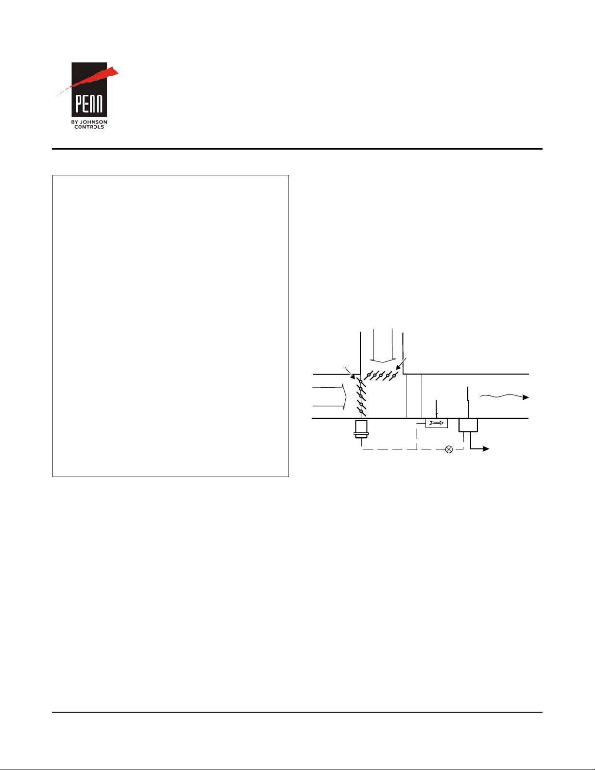
Figure 1: T ypical Application Inst allation fo r the
F240AA Pneumatic Airflow Switch
Normally
Open
Damper
Normally
Closed
Damper
Fan
Airflow
Switch
Control
Supply Air
20 psig
0.007 in.
(0.18 mm)
Pneumatic
Damper
Actuator
Return Air
Outside
Air
F240AA Pneumatic Airflow Switch
Installation Instructions
Part No. 24-7664-3124, Rev. A
Refer to the QuickLIT website for the most up-to-date version of this document.
Issued October 15, 2015
Applications
IMPORTANT: Use this F240AA Pneumatic Airflow
Switch only as an operating control. Where failure or
malfunction of the F240AA switch could lead to
personal injury or property damage to the controlled
equipment or other property , additional precautions
must be designed into the control system. Incorporate
and maintain other devices, such as supervisory or
alarm systems or safety or limit controls, intended to
warn of or protect against failure or malfunction of the
F240AA switch.
IMPORTANT: Utiliser ce F240AA Type Pneumatic
Airflow Switch uniquement en tant que dispositif de
régulation. Lorsqu'une défaillance ou un
dysfonctionnement du F240AA switch l risque de
provoquer des blessures ou d'endommager
l'équipement contrôlé ou un autre équipement, la
conception du système de contrôle doit intégrer des
dispositifs de protection supplémentaires. Veiller
dans ce cas à intégrer de façon permanente
d'autres dispositifs, tels que des systèmes de
supervision ou d'alarme, ou des dispositifs de
sécurité ou de limitation, ayant une fonction
d'avertissement ou de protection en cas de
défaillance ou de dysfonctionnement du
F240AA switch.
The F240AA Pneumatic Airflow Switch detects airflow
or the absence of airflow by responding only to the
velocity of air movement within a duct.
Typical applications include:
• make-up air systems
• air cooling or heating processes
• exhaust systems
The switch features a T ype 3R (NEMA)/IP43 en closure
with an integral mounting plate and a moun ting gasket.
It is calibrated for a maximum pneumatic input
pressure of 20 psig (138 kPa).
For a typical application installation for the
F240AA Pneumatic Airflow Switch, see Figure 1.
FIG:F240AA_smpl_app
Temperature
Restrictor
Absence of airflow during the normal operation of air
handling systems may cause overheating, coil icing, or
other conditions that may be detrimental to the
equipment.
F240AA Pneumatic Airflow Switch Installation Instructions
1
Page 2
Installation
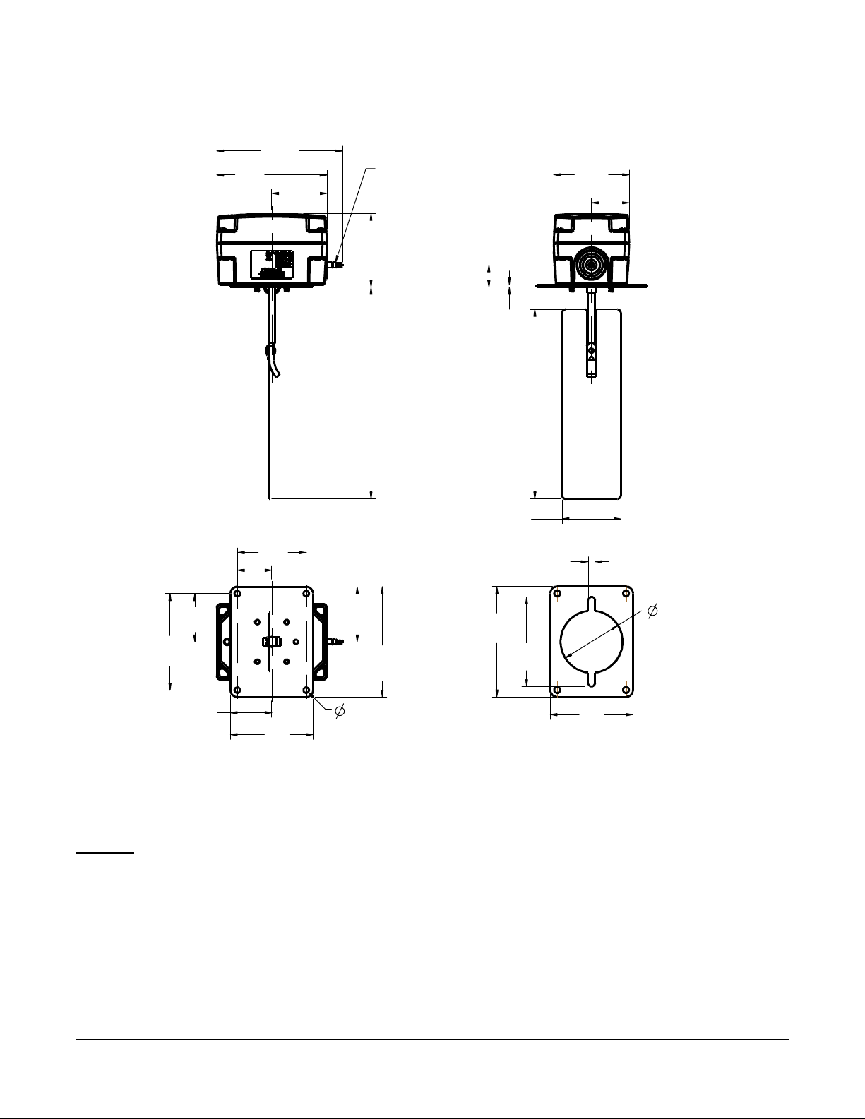
Figure 2: F240AA Airflow Switch with Type 3R (NEMA)/IP43 Enclosure Dimensions, in. [mm]
- -
1/4 [6] O.D. x
3/16 [4] I.D.
tubing
2
[51]
4
[102]
[116]
1-3/8
[35]
2-3/4
[70]
7-11/16
[197]
6-7/8
[175]
2-1/8 [54] Standard
3-1/8 [79] O pt ional
1/4 [6]
4
[102]
4
[102]
3-1/4
[83]
2
[51]
1-1/4
[32]
1-3/4
[45]
2-1/2
[64]
3-1/2
[89]
1-1/2
[38]
3
[76]
3
[76]
2-11/16
[68]
13/16
[21]
1/16
[2]
FIG:F240AA_dmnsns
3/16 [5] di am eter
mounting holes for
No. 10 screws, 4 places
[57]
Dimensions
4-9/16
Barbed connector for
2-1/4
Installation Procedure
Select the proper location and orientation. See
Mounting
1. Use the mounting plate gasket as a template and
2. Drill or punch screw holes.
.
mark hole positions.
3. Cut the center hole large enough for the paddle to
pass through.
4. Trim the paddle, if necessary (see Figure 3). The
standard paddle fits into ducts of 3 x 8 in.
(76 x 203 mm) minimum. Th e paddle ma y be
trimmed for installing in ducts as small as 3 x 6 in.
(76x152mm).
F240AA Pneumatic Airflow Switch Installation Instructions
2
Page 3
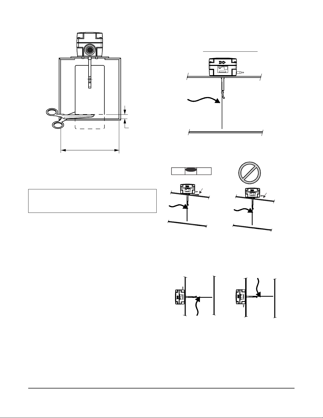
Figure 3: Trimming the Paddle,
Dimensions, in. [mm]
3-15/16
[100]
3/16
[5]
FIG:F240AA_mnt_trm
Figure 4: Mounting the F240AA Switch in a
Horizontal Duct
FIG:hrzntl_mntg_ F240AA
Figure 5: Mounting the F240AA Switch in an
Angled Duct
shim
FIG:mntng_angl_dct_F240AA
Figure 6: Mounting the F240AA Switch in a
Vertical Duct
FIG:vrtc l_mntg_F2 40AA
Mounting
IMPORTANT: Mount the switch so that the housing
is level horizontally (or plumb vertically). Use a shim,
if necessary.
• When mounting the switch in a vertical duct where
the airflow is downward (Figure 6), you must
readj ust the minimum flow required to actuate the
switch (see Setup and Adjustments
on page 4).
no shim
• Install the switch so that the cover and interior are
accessible for adjustment.
• Ensure that the arrow on the side of the switch
body points in the direction of flow.
• Mount the F240AA switch on the top, side, or
bottom of a duct.
• Mount the switch in a horizontal duct whenever
possible. In a horizontal duct, the switch housing
must be level, and the paddle should be at
approximately a right angle to the airflow
(Figure 4).
• When mounting the switch in a horizontal duct that
is not horizontally true, check with a le vel and place
a shim under the switch mounting plate. Do not
mount the switch without a shim (Figure 5).
• When mounting the switch in a vertical duct where
the airflow is upward (Figure 6), see T able 2 for the
minimum flow required to actuate the switch. The
maximum air velocity should not exceed
2,000 FPM (10.16 m/s).
Note: When the switch is mounted in a vertical duct,
the values shown in Figure 10 do not apply.
!
F240AA Pneumatic Airflow Switch Installation Instructions
3
Page 4

Location Considerations
Figure 7: Required Duct Distance
FLOW
FLOW
A
FIG:reqd_dc t_dstn
Figure 8: Flow Rate Adjustment
(Screw)
Flow Rate
Higher
Less airflow
required to
activate switchthe
More flow
required to
air
-
!
!
Setup and Adjustments
IMPORTANT: Mount the switch so that the housing
is level horizontally (or plumb vertically). Use a shim,
if necessary.
Do not use this switch where it is exposed to outdoor
weather. The switch is designed specifically for indoor
use.
Avoid locations close to elbows, dampers, fans, duct
openings, or other areas where excess ive tur bul en ce
occurs.
Mount the switch away from such areas at least five
times the distance of the smallest duct dimension
(Figure 7).
Example: On a 3 in. × 8 in. duct, mount the
F240AA switch at least 15 in. (381 mm) from the
nearest bend.
c
A
CAUTION: Risk of Property Damage.
Do not set the switch lower than the
factory setting. The switch is factory set
at approximately the minimum flow rate.
A lower setting may result in the switch
failing to return to a no-flow position
which may result in damage to the
controlled equipment or other property.
MISE EN GARDE : Risque de dégâts
matériels.
Ne pas régler le commutateur sur une
valeur inférieure au paramètre d'usine.
Le commutateur est réglé en usine sur
une valeur correspondant environ au
débit minimum. Un réglage sur une
valeur inférieure risque d'empêcher le
commutateur de revenir sur une position
« aucun-débit », ce qui risque
d'endommager l'équipement contrôlé ou
de provoquer d'autres dégâts matériels.
CAUTION: Risk of Property Damage.
Do not attempt to change sealed settings
(screws sealed with Threadlock®).
Attempted adjustment may damage th e
switch or cause loss of calibration or
other property damage.
Dimension A must be at least five times the distance
of the smal l est duct dimen sion.
The standard paddle fits into ducts of 3 x 8 in.
(76 x 203 mm) minimum. The paddle may be trimmed
for installing in ducts as small as 3 x 6 in.
(76 x 152 mm).
Lower
Flow Rate
activate the switch
+
Adjustment Bushing
MISE EN GARDE : Risque de dégâts
matériels.
Ne pas essayer de modifier la position
des éléments de réglage bloqués (vis
identifiées par de la peinture noire).
Toute tentative de réglage risque
d'endommager le dispositif de contrôle
ou de provoquer la perte des valeurs
d'étalonnage ou d'autres dégâts
matériels.
To adjust the setting of the flow switch:
1. Remove the enclosure cover.
2. Adjust the switch’s flow rate (Figure 8):
• Turn the adjustment screw counterclockwise
to lower the flow rate required to activate the
switch.
• Turn the adjustment screw clockwise to raise
the flow rate required to activate the switch.
Note: Do not lower the flow rate required to
FIG:ad jst_fl w_rte _F240AA
activate the switch, unless the flow rate required to
activate the switch was raised from the factory-set
flow rate.
F240AA Pneumatic Airflow Switch Installation Instructions
4
Page 5

3. Replace the enclosure cover and tighten the cover
Figure 9: Minimum Adjustment
DepressMainLeverHere
AdjustmentBushing(Screw)
screws with 10 to 12 in·lb of torque.
Verification
To verify that the flow rate is set above the factory
minimum, depress the main lever (see Figure 9)
multiple times.
If the lever fails to operate the switch upon return at any
time, the flow rate is set below the factory-set
minimum.
Turn the adjustment screw clockwise to raise the flow
rate required to activate the switch. See Figure 8.
Operation
The pneumatic airflow switch responds to pressure
exerted on the flow paddle by the velocity of air
movement within a duct. The control port closes on
increasing flow and opens on decreasing flow. See
Table 1 for switch action.
Table 1: Switch Action
Airflow Action Switch Action
Increasing Flow Closes
Decreasing Flow Opens
Table 2 and Figure 10 show airflow velocities in FPM
required to activate the switch for any given duct size
(horizontal or vertical upward flow). The flow rate is
based on a standard air density of 0.075 lb/ft
[1.2 kg/m
3
]. The switch is factory-set at the minimum
3
flow rate shown in Figure 10.
Table 2: Flow Rate Table, FPM (m/second)
Paddle
Width
2-1/8 in. Increasing Flow (Close) 625 (3.2) 575 (2.9) 950 (4.8) 750 (3.8)
3-1/8 in. Increasing Flow (Close) 500 (2.5) 350 (1.8) 750 (3.8) 500 (2.5)
Switch Actuation
on Flow
(323 cm
Duct Area
Decreasing Flow (Open) 325 (1.7) 220 (1.1) 850 (4.3) 575 (2.9)
Decreasing Flow (Open) 250 (1.3) 100 (0.5) 650 (3.3) 350 (1.8)
Minimum Air Velocity Required to Activate Control
Horizontal Flow Vertical Flow
2
50 in.
2
Larger
) or
Less Than
50 in.
(323 cm
Area
2
2
) Duct
(323 cm
Duct Area
2
50 in.
2
Larger
) or
Less Than
2
50 in.
(323 cm2)
Duct Area
F240AA Pneumatic Airflow Switch Installation Instructions
5
Page 6

Figure 10: Flow Rate Curve for an F240AA Switch Mounted in a Horizontal Duct
0
100
200
300
400
500
600
700
800
900
129 258 387 516 645
774
903 1032 1 161 1290 1419 1548 1677 1806 1935
4.5
4.0
3.5
3.0
2.5
2.0
1.5
1.0
0.5
30028026024022020018016014012010080604020
Duct Area, cm
2
Velo ci t y, m/ second
Duct Area, in.
2
Velocity, ft/min.
M
i
n
i
m
m
u
p
e
O
n
i
n
g
P
o
i
n
t
:
2
-
1
/
8
i
n
.
w
i
d
e
p
a
d
d
l
e
M
i
n
i
m
u
m
C
l
o
s
i
n
g
P
o
i
n
t
:
2
-
1
/
8
i
n
.
w
i
d
e
p
a
d
d
l
e
M
i
m
i
m
u
m
C
l
o
s
i
n
g
P
o
i
n
t
:
3
-
1
/
8
i
n
.
w
i
d
e
p
a
d
d
l
e
M
i
m
i
m
u
m
O
p
e
n
i
n
g
P
o
i
n
t
:
3
-
1
/
8
i
n
.
w
i
d
e
p
a
l
d
d
e
Closing Flow
Opening Flow
Checkout Procedure
Before you leave the installation, observe at least three
complete operating cycles to be sure that all
components are functioning correctly.
Repair Information
Do not make field repairs, except for replacement of
the flow paddle. For a replacement control or paddle
kit, contact the nearest Johnson Controls/PENN
distributor. For more information, contact
Johnson Controls/PENN® application engineering at
1-800-275-5676 or 1-414-524-5535.
Ordering Information
Table 3: F240AA Pneumatic Airflow Switch
Product Code Number Description
F240AA-01C Pneumatic airflow switch with Type 3R (NEMA)/IP43 enclosure,
Table 4: Replacement Paddle Kits
Product Code Number Description
PLT112-1R 2-1/8 in. wide x 6-7/8 in. long (54 mm x 175 mm) paddle
PLT112-2R 3-1/8 in. wide x 6-7/8 in. long (79 mm x 175 mm) paddle
2-1/8 in. wide x 6-7/8 in. long (54 mm x 175 mm) paddle installed and a
3-1/8 in. wide x 6-7/8 in. long (79 mm x 175 mm) paddle supplied.
F240AA Pneumatic Airflow Switch Installation Instructions
6
Page 7

Johnson Controls/PENN® and Johnson Controls® are registered trademarks of Johnson Controls, Inc.
in the United States of America and/or other countries. All other trademarks used herein are the property
of their respective owners. © Copyright 2015 by Johnson Controls, Inc. All rights reserved.
Building Efficiency
507 E. Michigan Street, Milwaukee, WI 53202
Technical Specifications
F240AA Pneumatic Airflow Switch
Switch Pneumatic
Ambient Operating Temperature 32 to 140°F (0 to 60°C)
Duct Air Temperature 32 to 104°F (0 to 40°C)
Maximum Air Velocity 2,000 FPM (10.16 m/sec)
Enclosure Type 3R (NEMA)/IP43, polycarbonate
Paddle Material 0.006 in. (0.15 mm) stainless spring steel
Pneumatic Switch Action Closes on increasing flow, opens on decreasing flow
Tubing Connector Barb fitting for 1/4 in. O.D. plastic tubing
Shipping Weight 1.3 lb (0.6 kg)
The performance specifications are nominal and conform to acceptable industry standards. For application at conditions beyond these
specifications, consult Johnson Controls/PENN Refrigeration Application Engineering at 1-800-275-5676. Johnson Controls, Inc. shall not be
liable for damages resulting from misapplication or misuse of its products.
F240AA Pneumatic Airflow Switch Installation Instructions
Published in U.S.A. www.johnsoncontrols.com
7
 Loading...