

Page 1

MODEL DSV
AIR CONDITIONING UNITS
INSTALLATION INSTRUCTIONS Supersedes:145.29-IOM2 (812) Form 145.29-IOM2 (814)
MODEL DSV60B-300B
VERTICAL R-410A
AIR CONDITIONING UNITS
STYLE B
Issue Date:
August 25, 2014
Page 2

IMPORTANT!
READ BEFORE PROCEEDING!
GENERAL SAFETY GUIDLINES
This equipment is a relatively complicated apparatus.
During installation, operation, maintenance or service,
individuals may be exposed to certain components or
conditions including, but not limited to: refrigerants
materials under pressure, rotating components, and
both high and low voltage. Each of these items has the
potential, if misused or handled improperly, to cause
bodily injury or death. It is the obligation and responsibilty of operating/service personnel to identify and
recognize these inherent hazards, protect themselves,
and proceed safely in completing their tasks. Failure to
comply with any of these requirements could result in
serious damage to the equipment and the property in
SAFETY SYMBOLS
The following symbols are used in this document to alert the reader to areas of potential hazard.
DANGER indicates an imminently hazardous situation which, if not avoided,
will result in death or serious injury.
WARNING indicates a potentially hazardous situation which, if not avoided,
could result in death or serious injury.
All wiring must be in accordance with published specifications and must be performed ONLY
by qualified service personnel. Johnson Controls will not be responsible for damages/problems
resulting from improper connections to the controls or application of improper control signals.
Failure to follow this will void the manufacturers warranty and cause serious damage to property or injury to persons.
, oils,
FORM 145.29-IOM2 (814)
which it is situated, as well as sever personal injury or
death to themselves and people at the site.
This document is intended for use by owner-authorized
operating/service personnel. It is expected that this
individual possesses independent training that will enable them to perform their assigned tasks properly and
safely. It is essential that, prior to performing any task
on this equipment, this individual shall have read and
understood this document and any referenced materials.
This individual shall also be familiar with and comply with
all applicable governmental standards and regulations
pertaining to the task in question.
CAUTION identifies a hazard which
could lead to damage to the machine,
damage to other equipment and/or
environmental pollution. Usually and
instruction will be given, together with a
brief explanation.
NOTE is used to highlight additional information which may be helpful to you.
2 JOHNSON CONTROLS
Page 3

CHANGEABILITY OF THIS DOCUMENT
In complying with Johnson Controls policy for continuous product improvement, the information contained in
this document is subject to change without notice.
While Johnson Controls makes no commitment to update or provide current information automatically to the
manual owner, that information, if applicable, can be
obtained by contacting the nearest Johnson Controls
service office.
TABLE OF CONTENTS
Safety Symbols………………………………………………………… 2
Changeability of This Document…………………….……………….. 3
Nomenclature……………………………………….………………….. 4
Typical Installation Diagram…………………………..………………. 5
General Information……………………………………………………. 6
Pre-Installation Inspection of Equipment……………………………. 6
Installation -
Unit Mounting / Unit Weights…………..……………………………..7
Evaporator / Condenser Assembly…………….…………………… 7
Condensate Trap…..…………………………………………………. 8
Ductwork………………………………………………………………. 9
Optional Accessories -
Variable Frequency Drive (VFD)………..……………………………9
Hot Gas Bypass (HGBP)……….…………….………………………10
Air Side Economizer…………….…………….………………………10
Discharge Plenum…………….……………..……..…………………11
Low Ambient Damper…………….…………..………………………12
Blower Discharge Conversion……..………………………………....13
Electrical Wiring / Electrical Data………………………………….. 13
Fan Performance Data……………………………………………….. 15
Motor and Pulley Data / Blower Speed Adjustment…………… 19
Start-Up and Operation………………………………………………. 21
Refrigerant Charges………………………………………………. 21
Pressure Switch Settings…………………………………………. 21
Microprocessor Controller……………………………………....…… 22
Operation……………………………….………………………….. 22
Microprocessor Flash Codes…………………………………….. 24
Maintenance/Service………………………………………………… 25
Appendix A: Unit Dimensional Drawings…………………………… 26
Appendix B: Typical Service Clearances……………………………36
Appendix C: Typical Wiring Schematics…………………………… 37
R-410A Service Procedures - Quick Reference Guide…………… 47
FORM 145.29-IOM2 (814)
It is the responsibility of operating/service personnel as
to the applicability of these documents to the
equipment in question. If there is any question in the
mind of operating/service personnel as to the
applicability of these documents, then, prior to working
on the equipment, they should verify with the owner
whether the equipment has been modified and if
current literature is available.
JOHNSON CONTROLS 3
Page 4

NOMENCLATURE
Product Category
DS =
Miscellaneous Options
A = None
D = Condensate Overflow Switch
Product Indentifier
V = Vertical, Free Standing Heating Options
0 = None
Nominal Capacity
060 = 5 TON Refrigerant Circuit Options
096 = 8 TON Design Series A = None
120 = 10 TON
B= Current B = Hot Gas Bypass
144 = 12 TON
180 = 15 TON
240 = 20 TON
VOLTAGE Condenser Drive Options
300 = 25TON
2 = 208/230-60-3
1 = Std Motor & Drive
4 = 460-60-3
2 = High Static Drive
5 = 575-60-3
Control Options
M = Std Microprocessor Controls Outdoor Air-side Options
A = Std Air-Side coil
C = Corrosion Protective Coating
ID Motor
1 = Std
2 = High Static Indoor Air-side Options
3 = Std cw VFD*
A = Std Air-Side coil
4 = High Static cw VFD* C = Corrosion Protective Coating
D = Stainless Steel Drain Pan
F = Coated Coil w/ S-S Drain Pan
Supply Air Discharge Configuration
V= Top Ve rtical
H=Front Horizontal
* VFD OPTION AVAILABLE ONLY ON 10 TONS AND UP
Integral Air-Cooled
Packaged A/C, R-410A
1AAMV2HDS120
B
1,2312134,5,6891071116
0
A
14
15A17
1
FORM 145.29-IOM2 (814)
4 JOHNSON CONTROLS
Page 5

DSV - TYPICAL INSTALLATION DIAGRAM
FORM 145.29-IOM2 (814)
JOHNSON CONTROLS 5
Page 6

FORM 145.29-IOM2 (814)
GENERAL INFORMATION
All models 8 ~ 25 tons are shipped as separate
condensing unit and evaporator section modules. The
5 ton models are shipped as factory-charged unitized
packages. All models are designed for freestanding
mounting on the floor, or on a field fabricated
structural steel stand. All models can be ordered in
either top or front fan discharge.
The 5 ton model utilizes a single compressor. All 8
through 25 ton models are dual compressor units with
two independent refrigerant circuits. The 8 ~ 25 ton
models require field connection and charging of the
refrigerant circuits. The 8 ~ 25 ton models are shipped
with a nitrogen holding charge only. Refer to ‘Start-Up
and Operation’ section for charge information.
All units come standard with a microprocessor control
board with safety controls and troubleshooting LED
(refer to ‘Microprocessor’ section).
Units will operate reliably at outdoor ambient down to
50F. In applications requiring operation below this
temperature, a low ambient damper accessory is
available. The damper installs on the condenser air
discharge, and allows operation to 0 F ambient.
ONLY QUALIFIED PERSONNEL SHOULD
PERFORM INSTALLATION AND SERVICE
OF THIS EQUIPMENT.
PRE-INSTALLATION INSPECTION OF EQUIPMENT
All units are factory tested to ensure safe operation
and quality assembly. Units are packaged and sealed
on shipping skids and shipped in first class condition.
Torn and broken packaging, scratched or dented
panels should be reported to carrier immediately.
Internal inspection of all units should be performed
prior to installation. Remove all access doors and
check for visual defects that can occur during
transport. Any problems found internally should be
reported to carrier and manufacturer immediately.
Refrigerant circuit should be checked to ensure no
leaks have occurred during shipment. Install gauge
set to high and low pressure ports to confirm pressure
has been maintained and no leaks have occurred
during shipment. Repair any damage prior to
installation to ensure safe operation.
See Appendix section for unit dimensional drawings.
Record any unit damage on the Bill of
Lading and report to carrier and factory
immediately. Shipping and handling
damages are not warranty items.
RIGGING
PRIOR TO MOUNTING UNIT, CHECK
INDIVIDUAL UNIT WEIGHTS (PAGE 10)
AND VERIFY LIFTING CAPACITY OF
LIFTING EQUIPMENT EXCEEDS WEIGHT
OF UNITS BY SAFE MARGINS. FAILURE
TO DO SO MAY RESULT IN UNIT
DAMAGE, PERSONAL INJURY OR EVEN
DEATH.
To ensure safe installation of the unit ensure the base
of the unit is continuously supported.
DETERMINE THE ACTUAL CENTER OF
GRAVITY OF THE UNIT BY PERFORMING A TEST LIFT. LIFTING AN UNBALANCED UNIT CAN CAUSE PERSONAL
INJURY OR EVEN DEATH.
INSTALLATION SITE
LOCK ALL ELECTRICAL POWER SUPPLY SWITCHES IN THE OFF POSITION
BEFORE INSTALLING THE UNIT. FAILURE TO DISCONNECT POWER SUPPLY
MAY RESULT IN ELECTRICAL SHOCK
OR EVEN DEATH.
Location - To ensure unit operates at maximum
efficiencies, choose a dry indoor area where the
temperature is controlled between 50F and 115F.
Consideration of surrounding areas should be taken
when choosing a location to install the unit. Common
vibration and sound levels associated with commercial
equipment may be objectionable to people or
equipment.
Failure to allow adequate space between
units, condenser intake and discharge
may result in poor unit performance and
possible unit failure.
Install thermostats, air supplies and returns so that
each unit will operate only on individual unit control.
To assure fast drainage of condensate run-off, unit
6 JOHNSON CONTROLS
Page 7

FORM 145.29-IOM2 (814)
DSV Operating Weight (Lbs)
Unit
Operating Weight
(Condenser Only)
Shipping Weight
(Condenser Only)
DSV060B
920 (620)
980 (675)
DSV096B
1240 (810)
1290 (865)
DSV120B
1325 (860)
1385 (915)
DSV144B
1560 (980)
1645 (1035)
DSV180B
1655 (1030)
1740 (1090)
DSV240B
1875 (1210)
1960 (1270)
DSV300B
2480 (1400)
2600 (1450)
Corner Bracket
can be slightly pitched in the same direction as drain
pan outlet.
UNIT MOUNTING
The 5 ton model is shipped as a fully assembled
integral package. The 8 ~ 25 ton models are shipped
in two pieces - a separate condensing unit and
evaporator module - which are intended for assembly
into a freestanding vertical package on site. The unit
is not designed for remote condenser / evaporator
installation and must be installed as a packaged
system. Installation or modification of the unit that is
not described in this manual is not factory
recommended nor is it factory supported. User is
responsible for any damage that as a result may
occur.
Flanges for all duct connections, corner securing
brackets, and refrigerant tubing couplings are shipped
in the condensing section of the unit for field
installation. Duct flanges for evaporator return are
incorporated into the filter rack.
Floor mounted units should be secured on a solid,
level pad or sturdy stand. The base of the unit should
be approximately 6 inches higher than the lower edge
of the wall opening. This height will allow the
condenser air ducts to be pitched away from the unit,
offering protection from rain water entering the base
pan (refer to typical installation diagram on Page 4).
The use of an isolating rubber sheet is recommended
to reduce vibration and noise transmission. Ensure
that the entire base is continuously supported. Unit
may be pitched slightly to ensure efficient drainage of
condensate.
Ensure that entire base is continuously
supported. DO NOT support unit at
corner points only!
EVAPORATOR / CONDENSER ASSEMBLY
ASSEMBLY OF SPLIT UNITS (8 - 25 TON MODELS)
- Place the condensing section in the required
location.
- Carefully position the evaporator section atop the
condensing section. Align all sides, the evaporator
motor wire routing hole, and the refrigerant line
routing holes.
- Install the securing brackets at all four corners, on
the evaporator/condenser separation joint.
Securing Corner Bracket
- Units are provided with couplings to mate
refrigerant piping between condenser and
evaporator section. Unit with Hot Gas Bypass
option will be provided with additional copper
couplings for the HGBP piping. Remove shipping
bracket securing spun copper ends in the
condenser, this can be discarded and is not
required.
- Cut off spun copper ends on each refrigerant pipe
in evaporator and condenser. Cut pipe to
appropriate length to fit on couplings. Ensure
circuit 1 from condenser connects to circuit 1
piping in evaporator, follow same procedure for
circuit 2. Do not cross circuits.
- Follow common A/C service practices by brazing
copper couplings to refrigerant pipe using a flow
of nitrogen gas (max. 1 psi) through the refrigerant
piping to minimize contamination to internal
piping. Otherwise damage to unit refrigeration
components may occur. Use the service gauge
ports for this procedure to introduce nitrogen flow.
Once complete pressure test with nitrogen (500
psig).
- Evacuate each circuit to at least 350 microns. If
gauge pressure rises above 500 microns in one
minute, evacuation is incomplete or the system
has a leak.
- Charge circuit(s) to the value indicated on the unit
nameplate or see section ‘Start-Up and
Operation’.
JOHNSON CONTROLS 7
Page 8

FORM 145.29-IOM2 (814)
Evaporator
connections,
couplings included
with unit
Condenser piping
for coupling to
evaporator
Condenser
Securing
Bracket
- Install bushing/clamp into evaporator wiring
routing hole, and pull wires through into electrical
control panel from evaporator. Connect motor
leads to load terminals on contactor/overload
relay.
Typical Piping Connections View (8/10 TON Model without
HGBP Shown)
Do not cross circuits when brazing
refrigerant piping between sections.
SEPARATION OF UNITS - (DSV060B MODEL)
If separation of units is required to pass through
doorways, elevators. Unit is not designed and not
certified to be installed as a remote condenser and
evaporator.
- Reclaim the entire refrigerant charge from each
compressor circuit.
- Disconnect the evaporator motor high voltage
wires. Pull all wiring into the evaporator
compartment. Remove bushing/clamp from
routing hole for evaporator motor wiring.
- Cut and remove sections of all liquid and suction
refrigerant lines. Make two cuts in each line,
approximately 6 inches above and below the
evaporator floor/condenser roof.
Use a TUBING CUTTER ONLY - do not
use a hacksaw to cut refrigerant tubing
otherwise serious damage can occur
to refrigeration system!
- Remove corner securing brackets from the
outside corners of the cabinet, at the joint line
between the evaporator and condenser sections.
- Remove the evaporator section.
- Refer to ‘Assembly of Split Units’ for assembly
instructions.
CONDENSATE TRAP
Unit requires a field installed external condensate trap
otherwise without a trap condensate can be thrown
into the air stream, cause water overflow resulting in
unit and property damage. This system must be
trapped according to a negative pressure (drawthrough) system. Use dimensions given below.
Adhere to local Codes for piping external trap and
condensate.
Example: Trapping a system up to 2” External static
pressure
A= (1” for each 1” of maximum negative static
pressure)) + 1”
B= Half of A
C= A + B + Pipe Diameter
Dimensions for trapping a negative pressure system
Example: Trapping a system up to 2” External static
pressure
A= (2”) + 1” B= A/2 C= A + B + 3/4” = 5-1/4”
8 JOHNSON CONTROLS
Page 9

FORM 145.29-IOM2 (814)
DUCTWORK
When installing ductwork, adhere to local Codes.
Minimize duct runs and avoid abrupt changes in
direction where possible. Allow ample access space
for servicing of the coils and changing of filters.
Perform regular maintenance on ducts to increase unit
life, maintain efficient operation, and reduce
accumulation of explosive dust. Refer to blower
performance charts, and engineer duct runs and
accessory pressure drop so as not to exceed
maximum external static values. Ensure continuous
running condenser intake ambient air temperature do
not exceed 115oF. The condenser exhaust should
discharge into an open area to prevent short cycling of
hot exhaust condenser air with the condenser intake.
Louver sizing guidelines
One of the key issues in obtaining optimum
performance from indoor air-conditioners is the proper
selection of the condenser intake and discharge
louvers. Unlike outdoor air cooled units, which intake
and discharge their cooling virtually unrestricted,
indoor units must overcome the resistance of grilles or
louvers at the outside wall - plus the restriction of any
interconnecting ductwork.
Our indoor air cooled air-conditioners are designed to
accommodate the external static pressure loss
associated with properly sized louvers of the "storm
proof” type. This type of louver typically has a free
area approximately 40-45% of the actual louver size.
To determine the free area required for any given unit,
adhere to the following guidelines:
- Size condenser air intakes for 350-600
feet/minute nominal velocity (Maximum
recommended 700 feet/minute)
- Size condenser air discharge for 1,200-1,500 feet
/minute nominal velocity (Maximum recommended
1,700 feet/minute)
The use of louvers with higher velocities than above
may be employed, at the discretion of the
engineer/installer, provided that the total air pressure
drop does not exceed the capability of the condenser
fan and motor. The use of low restriction louvers with
shallow blade angles can allow higher face velocities
without excessive static pressure loss.
Exceeding the static pressure capability of the
condenser fan will result in insufficient condenser air
volume. This will cause a loss in system capacity, and
may cause compressor shut-down during high
ambient periods. (Installation of an oversize
condenser motor/drive, where applicable, may be
considered in such cases.)
(As a general rule, these velocities will require an
intake louver sized approximately 1.25 to 1.5 times
the dimensions of the duct connection on the unit, and
a discharge louver sized approximately 1.5 to 2 times
the duct connection dimensions.)
Use only louver sections that provide different
deflection angles for air discharge and air intake,
to ensure the unit does not short circuit. Protect
the unit from weather conditions (rain, snow) entering
through the condenser air intake. All outdoor air
ducts should pitch away from the unit, toward the
outside wall. Connect all ducts to unit with canvas
section duct connectors or choose another suitable
noise and vibration absorbing device.
The Manufacturer will not accept any
liability resulting from incorrect installation of this equipment. Follow installation instructions carefully.
VARIABLE FREQUENCY DRIVE (VFD)
Optional VFD controller for the evaporator fan is
available on the 10 to 25 ton models. Mounted in the
in the evaporator module section, the VFD allows the
operator to set the duct static. The VFD will control the
frequency (speed) of the evaporator fan motor in order
to meet the desired supply duct static set point. For
reliable unit operation unit must have a factory
installed Hot Gas Bypass circuit on refrigeration circuit
# 1.
The unit does not carry a failsafe
circuit to bypass the VFD and run
the evaporator fan in the event of a
VFD malfunction.
VFD is factory mounted and wired. The installer must
field provide and install two sensor tubing lines
complete with static pressure probes. Installer is
required to field wire fan power wiring between
evaporator and condenser as a result of the unit being
shipped factory split. The power wiring can be found
inside the VFD enclosure, no extra power wiring is
required – sufficient length is provided. The VFD
option does not include a evaporator fan bypass
circuit in case of microdrive failure. Microdrive will
need to be replaced to re-activate unit. In case of
VFD failure the evaporator fan will stop running
however unit compressors will continue to run until a
low pressure safety trip is activated.
JOHNSON CONTROLS 9
Page 10

FORM 145.29-IOM2 (814)
Jumper set
to 4-20mA
4-20mA Output from
Transducer (–COM)
Transducer
Power (+EXC)
Refer to separate ‘VFD Installation and Operation
Manual’ for detailed installation and operation
instructions.
Do not run evaporator fan motor
below 30Hz otherwise coil freeze-up
and nuisance lock-outs may occur.
Building excessive ductwork
pressure can cause damage to unit
or personnel
VFD Input/Output
Note: Jumper is required between contacts 10 & 11
HOT GAS BYPASS (HGBP)
Optional HGBP on the lead compressor circuit (circuit
#1) meters flow of compressor discharge hot gas to
the system low side in order to balance the system
capacity to the space load requirement. HGBP is
factory installed using an adjustable hot gas regulator.
The bypassed hot gas from the compressor is
discharged to the evaporator inlet (i.e.: between the
TX valve and distributor) via a Tee connection.
Adjusting HGBP set point
The desired coil suction pressure or coil temperature
when the HGBP valve opens is selectable by
adjusting the screw on the HGBP valve. To set the
load run the unit and cool down the evaporator coil by
either shutting the fans or by blocking the airflow until
the suction pressure drops at least 5psi below the
desired evaporator coil setpoint. The next step is to
allow the pressure to be raised by the bypassed gas,
the screw spring adjustment can be set until the
HGBP valve closes at the desired set point.
The pressure of the evaporator coil is set to maintain
an evaporator coil temperature above the point where
frost and coil freeze up could form.
AIR SIDE ECONOMIZER
Optional air side economizer mixing box is designed
to attach the return air side of the evaporator. Mixing
comes with low-leakage opposed blade dampers.
Economizer is used to provide ventilation and free
cooling for the JCI DSV series of vertical air handlers.
Economizer setup is done through the LCD keypad
display locating on the economizer control module
mounted on the mixing box. Access to the mixing box
is required.
The factory supplied economizer includes:
economizer module, mixing box, actuator, enthalpy
sensor, temperature sensor, dampers, and wiring
harness. Refer to Appendix C for economizer
electrical wiring schematics.
SEQUENCE OF OPERATION
High enthalpy sequence
Enthalpy sensor should be located in the outdoor air
duct. When the outside air enthalpy exceeds the
enthalpy set-point, the economizer module Y1-In and
Y1-Out terminals are closed and economizer will be
forced into the minimum damper position setting. The
DSV unit’s microprocessor board will control
mechanical cooling requirements.
Low enthalpy sequence
When the outside air enthalpy is below the enthalpy
set-point, economizer module Y1-In and Y1-Out
terminals are opened and free cooling is activated.
The JCI unit’s microprocessor board turns off
compressor operation.
Damper Modulation
The temperature sensor should be located in the
supply discharge air duct. Locating the sensor in the
discharge air provides effective 'low-limit' sensing and
control. The outside-air damper remains at minimum
position if the discharge air temperature is below 500 F
or 100 C. If the discharge air temperature is between
500 to 560 F (100 to 13.30 C) the outside air damper
will modulate between minimum position and fully
open. Above 560 F (13.30 C) the outside air damper
will remain in the fully open position.
10 JOHNSON CONTROLS
Page 11

FORM 145.29-IOM2 (814)
Plenum Dimensions (Inches)
MODEL
W
D
H
Side Grille
Front Grille
DSV060B
52
29
24
16x12 (2x)
32x12
DSV096B
71.5
32
24
20x18 (2x)
48x18
DSV120B
71.5
32
24
20x18 (2x)
48x18
Plenum Dimensions (Inches)
MODEL
W
D
H
Side Grille
Front Grille
DSV144B
82.5
34
28
24x20 (2x)
28x20 (2x)
DSV180B
82.5
34
28
24x20 (2x)
28x20 (2x)
DSV240B
90.5
34
28
24x20 (2x)
32x20 (2x)
A B C D E
DSV060B VASE-060B-1 49.00 27.75 24.00 40.00 14.00
DSV096B/120B VASE-120B-1 66.50 36.25 26.50 58.00 19.50
DSV144B/180B VASE-180B-1 78.00 35.75 28.50 70.00 19.50
DSV240B VASE-240B-1 86.00 41.25 34.00 78.00 25.00
DSV300B VASE-300B-1 104.00 45.00 34.00 90.00 25.00
MODEL
PART NO.
MIXING BOX
DAMPER
1
FINISHED PRODUCTS
SPOT WELD WELD
INSULATE
PAINTING
NONONONO
6.75
3.625
EDB
TOP VIEW
FRONT VIEW
4
(vertical) discharge evaporator blower configuration.
Discharge plenum for 5 – 10 Ton model comes with
single front grille and single side grilles. The 12 – 20
Ton models come with double front grilles and single
side grilles.
Discharge plenum is constructed of heavy gauge
sheet metal with supply grilles mounted on three side
(front, left and right sides). Discharge plenum is
secured to the unit using 4X corner brackets included
with plenum.
Refer to separate ‘Air Side Economizer Installation
and Operation Manual’ for more detailed installation
and operation instructions.
DISCHARGE PLENUM
Optional discharge plenum is available for field
mounting to the top of evaporator for the 5-20 ton
models. Discharge plenum is only compatible with top
JOHNSON CONTROLS 11
Page 12

FORM 145.29-IOM2 (814)
MODEL PART NO. A B C
DSV060B VADK-060B-1 47.375" 5.0" 11.875"
DSV096B/120B VADK-120B-1 66.375" 5.0" 14.125"
DSV144B/180B VADK-180B-1 77.5" 5.0" 14.125"
DSV240B VADK-240B-1 85.5" 5.0" 12.875"
DSV300B VADK-300B-1 103.5" 5.0" 12.875"
LOW AMBIENT DAMPER INSTALLATION
If unit operation is required at outdoor ambient below
50 F, the optional Low Ambient Damper kit should be
installed to maintain acceptable condensing pressure.
The damper is installed directly onto the intake duct
connection as illustrated. The damper position is
determined by refrigerant pressure. A direct-coupled
electric damper actuator motor drives the damper
open or closed, depending on the output signal from a
proportional pressure control module. A pressure
transducer senses the high-side refrigerant pressure,
through a service access port, located on the liquid
refrigerant line leaving the condenser. The pressure
controller, complete with terminal connection blocks
for wiring, is attached to a field-installed mounting
bracket. Appropriate mounting hardware for the
pressure control module and the damper actuator
motor are provided with the kit. A routing hole is
provided in the condenser corner panel, near the
actuator mounting location, to allow installation of the
plenum-rated cable between the motor and the control
module.
12 JOHNSON CONTROLS
On dual compressor units, the pressure
transducer MUST be connected to the #1
circuit liquid line fitting. Connection to
the second stage refrigerant circuit will
result in system malfunction.
For detailed installation instructions, refer to the
supplementary ‘Low Ambient Damper Kit’
installation instructions.
Page 13

FORM 145.29-IOM2 (814)
EVAPORATOR BLOWER DISCHARGE
CONVERSION
All models can be factory ordered with either front or
top fan discharge.
Procedure for converting the fan discharge is similar
on all models. Original drive belts will need to be
replaced, see ‘Drive Belt’ section for alternate belt
information.
- Remove the panel attachment screws on the
alternate location access panel. Remove the
panel and set aside.
- Remove blower drive belt on all models with
base mounted motors.
- Remove the panel attachments screws on the
blower mounting panel. Do not remove fasteners
securing blowers to panel! The blowers are to
remain attached to the mounting panel at all
times.
- Carefully remove the blower panel assembly
from the evaporator cabinet. Do not allow blower
housings to contact the evaporator coil during the
removal. On some models, the housing(s) will
have to be "rotated" to exit through the panel
opening.
- Interchange the blower panel assembly with the
position of the alternate access panel. Exercise
care in locating the panel. Do not allow blower
housings to contact the evaporator coil. Install
the attachment screws and tighten securely.
- Install the blank access panel into the remaining
evaporator opening. Fasten securely.
- Install new drive belts.
- Adjust drive belts to appropriate tension. Test run
blower and observe operation for unusual
sounds or vibration.
ELECTRICAL WIRING
Follow local electrical codes when making electrical
connections. Units are completely factory wired for
normal supply voltages (ie.208-230, 460,
575V/3Ph/60Hz) Confirm unit specifications by
checking unit data plate. All electrical components are
accessible through an independent electrical panel
located on the "front" face of the condensing section.
The electrical control boxes are located behind outer
access panels. The condenser section electrical cover
is installed with wiring diagrams on the inside, which
must be opened to be read.
Ensure evaporator motor rotation is
correct upon unit start-up. Switch any
two wires at contactor if blower rotation
is not correct.
DISCONNECT AND LOCK OUT POWER
WHEN SERVICING UNIT. UNIT MAY
START AUTOMATICALLY IF POWER IS
NOT DISCONNECTED. FAILURE TO DO
SO MAY RESULT IN PERSONAL INJURY OR DEATH DUE TO ELECTRICAL
SHOCK.
If canvas flexible joints are used on ductwork, install a
ground wire to the ductwork as well.
IMPORTANT: All wiring must comply
with applicable local and national codes
(NEC). Type and location of disconnect
switches must comply with all
applicable codes.
For low voltage thermostat wiring, 18 gauge wire may
be used for up to 50 feet lengths. Low voltage runs up
to 125 feet require 16 gauge wire.
JOHNSON CONTROLS 13
Page 14

FORM 145.29-IOM2 (814)
ELECTRICAL DATA - STANDARD EVAPORATOR MOTOR
MODEL #
VOLTAGE
COMPRESSOR
EVAP.
FAN
COND. FAN
MCA
MAX FUSE
/ CCT.
BKR. AMP
QTY RLA
LRA
HP
FLA
HP
FLA
DSV060B2
208-230/3/60
1 @ 16.0
110.0
1.00
3.1
1.50
4.5
27.60
40
DSV060B4
460/3/60
1 @ 7.8
52.0
1.00
1.5
1.50
2.2
13.45
20
DSV060B5
575/3/60
1 @ 5.7
38.9
1.00
1.2
1.50
1.8
10.13
15
DSV096B2
208-230/3/60
2 @ 15.3
83.0
1.00
3.1
2.00
5.8
43.33
50
DSV096B4
460/3/60
2 @ 6.2
41.0
1.00
1.5
2.00
2.9
18.35
20
DSV096B5
575/3/60
2 @ 4.8
33.0
1.00
1.2
2.00
2.3
14.30
15
DSV120B2
208-230/3/60
2 @ 16.0
110.0
1.50
4.5
3.00
8.5
49.00
60
DSV120B4
460/3/60
2 @ 7.8
52.0
1.50
2.2
3.00
4.2
23.95
30
DSV120B5
575/3/60
2 @ 5.7
38.9
1.50
1.8
3.00
3.4
18.03
20
DSV144B2
208-230/3/60
2 @ 19.0
123.0
2.00
5.8
3.00
8.5
57.05
70
DSV144B4
460/3/60
2 @ 9.7
62.0
2.00
2.9
3.00
4.2
28.93
35
DSV144B5
575/3/60
2 @ 7.4
50.0
2.00
2.3
3.00
3.4
22.35
25
DSV180B2
208-230/3/60
2 @ 23.2
164.0
3.00
8.5
5.00
14.0
74.70
90
DSV180B4
460/3/60
2 @ 11.2
75.0
3.00
4.2
5.00
6.6
36.00
45
DSV180B5
575/3/60
2 @ 7.9
54.0
3.00
3.4
5.00
5.3
26.48
30
DSV240B2
208-230/3/60
2 @ 30.1
225.0
5.00
14.0
7.50
19.4
101.13
125
DSV240B4
460/3/60
2 @ 16.7
114.0
5.00
6.6
7.50
9.7
53.88
70
DSV240B5
575/3/60
2 @ 12.2
80.0
5.00
5.3
7.50
7.8
40.55
50
DSV300B2
208-230/3/60
2 @ 34.0
240.0
7.50
20.4
10.00
25.0
121.90
150
DSV300B4
460/3/60
2 @ 16.0
140.0
7.50
9.7
10.00
12.5
58.20
70
DSV300B5
575/3/60
2 @ 12.9
107.6
7.50
7.8
10.00
10.0
46.83
50
ELECTRICAL DATA - OVERSIZED EVAPORATOR MOTOR
MODEL #
VOLTAGE
COMPRESSOR
EVAP.
FAN
COND. FAN
MCA
MAX FUSE
/ CCT.
BKR. AMP
QTY RLA
LRA
HP
FLA
HP
FLA
DSV060B2
208-230/3/60
1 @ 16.0
110.0
1.50
4.5
1.50
4.5
29.00
45
DSV060B4
460/3/60
1 @ 7.8
52.0
1.50
2.2
1.50
2.2
14.15
20
DSV060B5
575/3/60
1 @ 5.7
38.9
1.50
1.8
1.50
1.8
10.73
15
DSV096B2
208-230/3/60
2 @ 15.3
83.0
1.50
4.5
2.00
5.8
44.73
60
DSV096B4
460/3/60
2 @ 6.2
41.0
1.50
2.2
2.00
2.9
19.05
25
DSV096B5
575/3/60
2 @ 4.8
33.0
1.50
1.8
2.00
2.3
14.90
15
DSV120B2
208-230/3/60
2 @ 16.0
110.0
2.00
5.8
3.00
8.5
50.30
60
DSV120B4
460/3/60
2 @ 7.8
52.0
2.00
2.9
3.00
4.2
24.65
30
DSV120B5
575/3/60
2 @ 5.7
38.9
2.00
2.3
3.00
3.4
18.53
20
DSV144B2
208-230/3/60
2 @ 19.0
123.0
3.00
8.5
3.00
8.5
59.75
70
DSV144B4
460/3/60
2 @ 9.7
62.0
3.00
4.2
3.00
4.2
30.23
35
DSV144B5
575/3/60
2 @ 7.4
50.0
3.00
3.4
3.00
3.4
23.45
30
DSV180B2
208-230/3/60
2 @ 23.2
164.0
5.00
14.0
5.00
14.0
80.20
100
DSV180B4
460/3/60
2 @ 11.2
75.0
5.00
6.6
5.00
6.6
38.40
45
DSV180B5
575/3/60
2 @ 7.9
54.0
5.00
5.3
5.00
5.3
28.38
35
DSV240B2
208-230/3/60
2 @ 30.1
225.0
7.50
20.4
7.50
20.4
108.53
125
DSV240B4
460/3/60
2 @ 16.7
114.0
7.50
9.7
7.50
9.7
56.98
70
DSV240B5
575/3/60
2 @ 12.2
80.0
7.50
7.8
7.50
7.8
43.05
50
14 JOHNSON CONTROLS
Page 15

FAN PERFORMANCE
SUPPLY AI R BLOWER PERFORMANCE
RPM BHP RPM BHP RPM BHP RPM BHP RPM BHP RPM BHP RPM BHP RPM BHP
1600 408 0.13 555 0.29 652 0.38 739 0.45 819 0.54 893 0.63 963 0.71 1029 0.81
1800 459 0.20 600 0.39 689 0.48 770 0.58 846 0.66 917 0.76 984 0.86 1047 0.96
2000 510 0.25 647 0.51 729 0.61 806 0.71 877 0.81 944 0.92 1008 1.00 1069 1.14
2200 561 0.35 695 0.65 772 0.76 843 0.88 911 0.99 975 1.10 1036 1.23 1094 1.34
2400 612 0.45 745 0.83 816 0.95 883 1.07 947 1.19 1008 1.31 1066 1.44 ~ ~
1. Blower performance includes evaporator coil and 2" filters
2. At higher evaporator airflows and wet bulb conditions, condensate carry-over may occur. Decrease airflow downward as necessary.
CONDENSER FAN PERFORMANCE
RPM BHP RPM BHP RPM BHP RPM BHP RPM BHP RPM BHP RPM BHP
3100 513 0.50 615 0.65 706 0.80 790 0.98 867 1.15 938 1.33 1006 1.50
Hi-Static Drive
Standard Factory Drive 1.5 HP
SUPPLY
CFM
0.2
0.4
0.6
0.8
1.0
1.2
1.4
0.0
AVAILABLE EXTERNAL STATIC PRESSURE - Inches W.C. ¹
Optional Hi-Static Drive +1 .5 HP
OUTDOOR
CFM
AVAILABLE EXTERNAL STATIC PRESSURE - Inches W.C.
0.0
0.2
0.4
0.6
0.8
1.0
1.2
Standard Factory Drive + 1 HP
Field Supplied Low Static
Drive
SUPPLY AI R BLOWER PERFORMANCE
RPM BHP RPM BHP RPM BHP RPM BHP RPM BHP RPM BHP RPM BHP RPM BHP RPM BHP RPM BHP
2600 496 0.28 605 0.40 701 0 .50 788 0.62 868 0.74 947 0.89 1016 1.04 1045 1.19 1075 1.35 1105 1.50
2900 514 0.36 618 0.48 710 0 .60 794 0.72 872 0.86 944 0.98 1017 1.12 1075 1.28 1128 1.42 ~ ~
3200 538 0.44 636 0.58 725 0 .70 806 0.84 881 0.98 952 1.12 1018 1.26 1081 1.42 ~ ~ ~ ~
3500 571 0.56 664 0.70 748 0 .84 826 0.98 898 1.14 967 1.28 1031 1.44 ~ ~ ~ ~ ~ ~
3800 613 0.70 700 0.86 779 1 .00 853 1.16 923 1.32 989 1.48 ~ ~ ~ ~ ~ ~ ~ ~
1. Blower performance includes evaporator coil and 2" filters
2. At higher evaporator airflows and wet bulb conditions, condensate carry-over may occur. Decrease airflow downward as necessary.
CONDENSER FAN PERFORMANCE
RPM BHP RPM BHP RPM BHP RPM BHP RPM BHP RPM BHP RPM BHP
4400 478 0.60 560 0.78 634 0 .96 702 1.14 765 1.34 824 1.54 880 1.74
Standard Factory Drive + 2 HP
Optional Hi-Static Drive + 2 HP
OUTDOOR
CFM
AVAILABLE EXTERNAL STATIC PRESSURE - Inches W.C.
0.0
0.2
0.4
0.6
0.8
1.0
1.2
Optional Hi-Static Drive + 1.5 HP
Standard Factory Drive + 1 HP
Low Static
Drive
SUPPLY
CFM
0.2
0.4
0.6
0.8
1.0
1.2
1.4
1.6
1.8
2.0
AVAILABLE EXTERNAL STATIC PRESSURE - Inches W.C. ¹
DSV060B
FORM 145.29-IOM2 (814)
DSV096B
JOHNSON CONTROLS 15
Page 16

DSV120B
SUPPLY AI R BLOWER PERFORMANCE
RPM BHP RPM BHP RPM BHP RPM BHP RPM BHP RPM BHP RPM BHP RPM BHP RPM BHP RPM BHP
3200 573 0.48 668 0.62 754 0.76 833 0.88 906 1.02 975 1.18 1040 1.32 1102 1.48 1160 1.66 1225 1.86
3600 621 0.66 708 0.80 788 0.96 863 1.10 933 1.26 999 1.42 1061 1.58 1121 1.74 1178 1.90 ~ ~
4000 667 0.86 748 1.02 823 1.18 893 1.34 960 1.52 1023 1.68 1083 1.86 1141 2.04 ~ ~ ~ ~
4400 723 1.12 797 1.28 868 1.46 934 1.64 997 1.84 1057 2.02 ~ ~ ~ ~ ~ ~ ~ ~
4800 775 1.40 845 1.60 911 1.80 973 2.00 ~ ~ ~ ~ ~ ~ ~ ~ ~ ~ ~ ~
1. Blower performance includes evaporator coil and 2" filters
2. At higher evaporator airflows and wet bulb conditions, condensate carry-over may occur. Decrease airflow downward as necessary.
CONDENSER FAN PERFORMANCE
RPM BHP RPM BHP RPM BHP RPM BHP RPM BHP RPM BHP RPM BHP
5500 614 1.22 680 1.44 741 1.66 799 1.90 854 2.14 906 2.38 956 2.62
Standard Factory Drive + 1.5 HP
Low Static
Drive
Optional Hi-Static Drive + 2 HP
Opt. Hi-Static Drive +3HP
Standard Factory Drive + 3 HP
OUTDOOR
CFM
AVAILABLE EXTERNAL STATIC PRESSURE - Inches W.C.
0.0
0.2
0.4
0.6
0.8
1.0
1.2
SUPPLY
CFM
AVAILABLE EXTERNAL STATIC PRESSURE - Inches W.C. ¹
0.2
0.4
0.6
0.8
1.0
1.2
1.4
1.6
1.8
2.0
SUPPLY AI R BLOWER PERFORMANCE
RPM BHP RPM BHP RPM BHP RPM BHP RPM BHP RPM BHP RPM BHP RPM BHP RPM BHP RPM BHP
4000 436 0.48 521 0.64 597 0.80 667 0.98 730 1.16 790 1.34 845 1.54 896 1.75 946 2.01 992 2.29
4400 456 0.58 536 0.76 609 0.94 676 1.12 738 1.32 796 1.52 851 1.72 902 1.82 950 2.17 996 2.52
4800 475 0.70 555 0.88 621 1.08 686 1.28 746 1.48 803 1.70 857 1.92 908 2.14 956 2.36 1000 2 .70
5200 494 0.84 567 1.04 634 1.24 697 1.46 755 1.68 811 1.90 863 2.12 913 2.36 961 2.60 1007 2 .84
5600 517 1.00 587 1.22 651 1.44 711 1.66 768 1.90 822 2.14 873 2.38 922 2.62 969 2.86 ~ ~
1. Blower performance includes evaporator coil and 2" filters
2. At higher evaporator airflows and wet bulb conditions, condensate carry-over may occur. Decrease airflow downward as necessary.
CONDENSER FAN PERFORMANCE
RPM BHP RPM BHP RPM BHP RPM BHP RPM BHP RPM BHP RPM BHP
6000 535 1.02 609 1.28 679 1.56 744 1.84 805 2.14 862 2.44 921 2.82
SUPPLY
CFM
AVAILABLE EXTERNAL STATIC PRESSURE - Inches W.C. ¹
0.2
0.4
0.6
0.8
1.0
1.2
1.4
1.6
1.8
2.0
OUTDOOR
CFM
AVAILABLE EXTERNAL STATIC PRESSURE - Inches W.C.
0.0
0.2
0.4
0.6
0.8
1.0
1.2
Standard Factory Drive + 3 HP
Optional Hi-Static Drive + 3 HP
Field Supplied Low Static Drive
Standard Factory Drive + 2 HP
Optional Hi-Static Drive + 3 HP
FORM 145.29-IOM2 (814)
DSV144B
16 JOHNSON CONTROLS
Page 17

DSV180B
SUPPLY AI R BLOWER PERFORMANCE
RPM BHP RPM BHP RPM BHP RPM BHP RPM BHP RPM BHP RPM BHP RPM BHP RPM BHP RPM BHP
4800 529 0.84 601 1.02 667 1.22 729 1.42 786 1.64 841 1.84 893 2.06 942 2.28 987 2.54 1037 2 .78
5400 580 1.14 646 1.36 707 1.58 764 1.80 819 2.02 870 2.26 920 2.50 967 2.74 1012 2.98 1056 3.2 4
6000 610 1.42 671 1.66 729 1.90 783 2.14 835 2.40 885 2.64 933 2.90 979 3.16 1023 3.44 1066 3.7 0
6600 702 2.04 757 2.30 809 2.56 858 2.84 906 3.10 952 3.38 996 3.66 1039 3.96 1080 4.24 1121 4.54
7200 760 2.62 810 2.90 858 3.18 905 3.48 950 3.78 993 4.08 1035 4.38 1076 4.68 1116 5.00 ~ ~
1. Blower performance includes evaporator coil and 2" filters
2. At higher evaporator airflows and wet bulb conditions, condensate carry-over may occur. Decrease airflow downward as necessary.
CONDENSER FAN PERFORMANCE
RPM BHP RPM BHP RPM BHP RPM BHP RPM BHP RPM BHP RPM BHP
7200 642 1.78 706 2.08 766 2.40 823 2.74 877 3.08 929 3.42 979 3.78
Standard Factory Drive + 5 HP
Optional Hi-Static Drive + 5 HP
Standard Factory Drive + 3 HP
Optional Hi-Static Drive + 5 HP
Field Supplied Low Static Drive
OUTDOOR
CFM
AVAILABLE EXTERNAL STATIC PRESSURE - Inches W.C.
0.0
0.2
0.4
0.6
0.8
1.0
1.2
SUPPLY
CFM
AVAILABLE EXTERNAL STATIC PRESSURE - Inches W.C. ¹
0.2
0.4
0.6
0.8
1.0
1.2
1.4
1.6
1.8
2.0
SUPPLY AI R BLOWER PERFORMANCE
RPM BHP RPM BHP RPM BHP RPM BHP RPM BHP RPM BHP RPM BHP RPM BHP RPM BHP RPM BHP
6400 592 1.38 659 1.63 721 1.96 779 2.26 835 2.58 888 2.88 942 3.02 1001 3.38 1058 3.76 1101 4.18
7200 645 1.88 706 2.18 770 2.50 818 2.84 870 3.18 920 3.52 965 3.88 1014 4.24 1065 4.61 1113 4.98
8000 698 2.46 769 2.80 808 3.14 858 3.50 907 3.88 954 4.26 1000 4.64 1044 5.02 1087 5.42 1128 5.82
8800 756 3.20 808 3.56 858 3.96 905 4.34 951 4.72 995 5.14 1038 5.54 1080 5.96 1121 6.38 1160 6.82
9600 811 4.04 859 4.44 905 4.84 950 5.26 993 5.68 1035 6.12 1076 6.56 1116 7.00 1154 7.45 ~ ~
1. Blower performance includes evaporator coil and 2" filters
2. At higher evaporator airflows and wet bulb conditions, condensate carry-over may occur. Decrease airflow downward as necessary.
CONDENSER FAN PERFORMANCE
RPM BHP RPM BHP RPM BHP RPM BHP RPM BHP RPM BHP RPM BHP
10800 775 3.87 827 4.29 877 4.71 925 5.16 971 5.61 1016 6.06 1052 7.0 0
Field Supplied Low Static Drive
Standard Factory Drive + 5 HP
Optional Hi-Static Drive + 7.5 HP
Standard Factory Drive + 7.5 HP
OUTDOOR
CFM
AVAILABLE EXTERNAL STATIC PRESSURE - Inches W.C.
0.0
0.2
0.4
0.6
0.8
1.0
1.2
SUPPLY
CFM
AVAILABLE EXTERNAL STATIC PRESSURE - Inches W.C. ¹
0.2
0.4
0.6
0.8
1.0
1.2
1.4
1.6
1.8
2.0
FORM 145.29-IOM2 (814)
DSV240B
JOHNSON CONTROLS 17
Page 18
DSV300B
SUPPLY AI R BLOWER PERFORMANCE
RPM BHP RPM BHP RPM BHP RPM BHP RPM BHP RPM BHP RPM BHP RPM BHP RPM BHP RPM BHP
8200 581 1.80 647 2 .16 707 2.49 765 2.85 819 3.24 870 3.60 920 3.99 967 4.38 1012 4.80 1056 5.19
8800 639 2.31 699 2 .70 755 3.06 809 3.45 860 3.84 910 4.26 957 4.65 1002 5.07 1045 5.49 1087 5.94
9200 676 2.70 733 3 .09 787 3.48 839 3.87 888 4.29 935 4.71 981 5.13 1025 5.58 1068 6.00 1109 6.45
9600 716 3.15 771 3 .54 822 3.96 872 4.38 920 4.80 965 5.25 1010 5.7 0 1052 6.15 1093 6.60 1113 7.05
10000 755 3.63 807 4.05 856 4.47 904 4.92 950 5.37 994 5.82 1037 6.27 1079 6.75 1119 7.20 ~ ~
1. Blower performance includes evaporator coil and 2" filters
2. At higher evaporator airflows and wet bulb conditions, condensate carry-over may occur. Decrease airflow downward as necessary.
CONDENSER FAN PERFORMANCE
RPM BHP RPM BHP RPM BHP RPM BHP RPM BHP RPM BHP RPM BHP
12800 735 4.41 790 4.98 843 5.55 894 6.15 944 6.78 992 7.41 1031 8.01
SUPPLY
CFM
AVAILABLE EXTERNAL STATIC PRESSURE - Inches W.C. ¹
0.2
0.4
0.6
0.8
1.0
1.2
1.4
1.6
1.8
2.0
Optional Hi-Static Drive + 10HP
Field Supplied Low Static Drive
OUTDOOR
CFM
AVAILABLE EXTERNAL STATIC PRESSURE - Inches W.C.
0.0
0.2
0.4
0.6
0.8
1.0
1.2
Standard Factory Drive + 7.5HP
Optional Hi-Static Drive +7.5HP
Standard Factory Drive + 10HP
FORM 145.29-IOM2 (814)
18 JOHNSON CONTROLS
Page 19

MOTOR AND PULLEY DATA
Frame Pitch Dia. Browning Pitch Dia. Browning
Size (in) Part No. (in) Part No.
DSV060B 568-852 1 145 1.9-2.9 1VP34X7/8 6.2 AK64H A28 A36
DSV096B 593-890 1 145 1.9-2.9 1VP34X7/8 5.9 AK61H A42 A51
DSV120B 614-921 1.5 145 1.9-2.9 1VP34X7/8 5.7 AK59H AX42 AX51
DSV144B 555-768 2 145 2.4-3.4 1VP40X7/8 8.2 AK84H AX46 AX55
DSV180B 640-854 3 184 2.8-3.8 1VP44X1 1/8 8.2 AK84H AX45 AX52
DSV240B 769-965 5 184 4.7-5.9 1VP60X1 1/8 10.4 BK110H B56 B65
DSV300B 716-882 7.5 213 5.2-6.4 1VP65X1 3/8 12.7 BK130H BX65 BX75
Frame Pitch Dia. Browning Pitch Dia. Browning
Size (in) Part No. (in) Part No.
DSV060B 803-1112 1.5 145 2.4-3.4 1VP40X7/8 5.7 AK59H A28 A36
DSV096B 745-1117 1.5 145 1.9-2.9 1VP34X7/8 4.7 AK49H AX40 AX49
DSV120B 843-1167 2 145 2.4-3.4 1VP40X7/8 5.2 AK56H AX42 AX51
DSV144B 724-925 3 184 3.4-4.4 1VP50X1 1/8 8.7 AK89H AX46 AX55
DSV180B 837-1027 5 184 4.4-5.4 1VP56X1 1/8 9.2 BK95H BX48 BX55
DSV240B 949-1145 7.5 213 5.4-6.6 1VP71X1 3/8 10.4 BK110H BX57 BX66
DSV300B 850-1047 7.5 213 5.2-6.4 1VP65X1 3/8 10.4 BK110H BX61 BX72
Frame Pitch Dia. Browning Pitch Dia. Browning
Size (in) Part No. (in) Part No.
DSV060B 568-852 1.5 145 1.9-2.9 1VP34X7/8 6.9 AK71H AX70
DSV096B 486-729 2 145 1.9-2.9 1VP34X7/8 7.2 AK74H AX68
DSV120B 640-854 3 184 2.8-3.8 1VP44X1 1/8 8.2 AK84H AX70
DSV144B 571-761 3 184 2.8-3.8 1VP44X1 1/8 9.2 AK94H AX79
DSV180B 686-866 5 184 3.4-4.4 1VP50X1 1/8 9.7 BK100H BX80
DSV240B 769-965 7.5 213 4.8-5.2 1VP60X1 3/8 10.4 BK110H BX89
DSV300B 741-894 10 215 5.8-7.0 1VP71X1 3/8 13.7 BK140H BX103
Frame Pitch Dia. Browning Pitch Dia. Browning
Size (in) Part No. (in) Part No.
DSV060B 568-852 1.5 145 1.9-2.9 1VP34X7/8 5.2 AK54H A68
DSV096B 486-729 2 145 1.9-2.9 1VP34X7/8 5.4 AK56H AX65
DSV120B 640-854 3 184 2.8-3.8 1VP44X1 1/8 6.9 AK71H AX68
DSV144B 571-761 3 184 2.8-3.8 1VP44X1 1/8 7.7 AK79H AX76
DSV180B 686-866 5 184 3.4-4.4 1VP50X1 1/8 8.3 BK85H BX77
DSV240B 769-965 7.5 213 4.8-5.2 1VP60X1 3/8 9.7 BK100H BX87
DSV300B 854-1020 10 215 6.2-7.4 1VP75X1 3/8 12.7 BK130H BX103
Belts
Belts
EVAPORATOR-STANDARD BLOWER MOTOR AND DRIVE DATA
Drive
Range
(RPM)
Motor
HP
Adjustable
EVAPORATOR-OVERSIZED BLOWER MOTOR AND DRIVE DATA
Model
Drive
Range
(RPM)
Motor
Adjustable
Fixed
Motor Pulley
Model
Blower Pulley
HP
Motor Pulley
Fixed
Blower Pulley
Horizontal
Discharge
Vertical
Discharge
Horizontal
Discharge
Model
Drive
Range
(RPM)
Motor
Adjustable
Fixed
Belts
Motor Pulley
Blower Pulley
HP
Standard
CONDENSER-STANDARD BLOWER MOTOR AND DRIVE DATA
Vertical
Discharge
CONDENSER-OVERSIZED DRIVE DATA
Model
Drive
Range
(RPM)
Motor
Adjustable
Fixed
Belts
Motor Pulley
Blower Pulley
HP
Standard
FORM 145.29-IOM2 (814)
JOHNSON CONTROLS 19
Page 20

FORM 145.29-IOM2 (814)
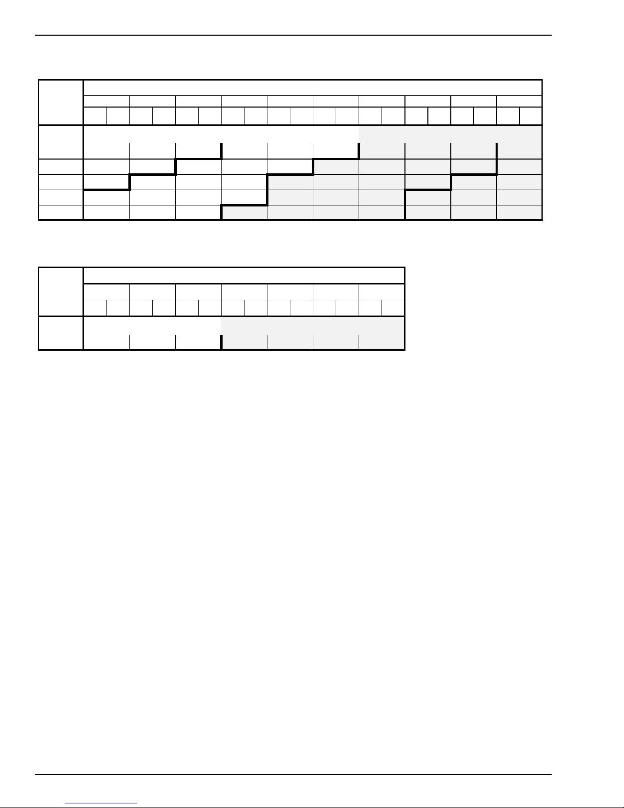
BLOWER SPEED ADJUSTMENT
The blower speed can be adjusted to increase or decrease the unit CFM for non-VFD units. The RPM of the
supply air and condenser air blowers will depend on the required CFM, and the static resistances of both the
supply/discharge and the return/intake duct systems.
An air balance should be done after installation to verify air flow and static. Adjustments to drive may be required.
Only operate unit in the regions defined by the fan tables. Units can be ordered with oversized motors and/or
drive kits for high static requirements.
Units with oversized motors or oversized drive kits are designed to operate in the shaded
region of the fan table otherwise motor amp draw will exceed overload setting resulting in
overload trips and possible damage to unit. Refer to fan tables for recommended operating
range of standard and oversized motors and drive kits.
The RPM for the blowers can be determined from the blower performance tables. Adjustment of blower speed is
accomplished as follows:
1) Loosen belt tension by moving motor towards the blower shaft via the adjustable mounting.
2) Loosen the setscrew in the adjustable motor pulley flange. Remove external key on pulleys 4 in. diameter and
larger.
3) Blower speed will increase when moveable flange is adjusted towards the fixed flange (closed). Blower speed
will decrease when the moveable flange is adjusted away from the fixed flange (opened). Pulleys are
adjustable only in half-turn increments. Do not open pulley more than five full turns for "4L" and "A" belts, or
six full turns for "B" belts.
4) Once the pulley has been opened/closed the appropriate number of turns, replace the external key and
tighten the adjustment setscrew. Proper torque is 110-130 in.-lbs.
5) Install drive belt and adjust motor mount to tension belt (see page 20: MAINTENANCE/SERVICE for further
information).
20 JOHNSON CONTROLS
Page 21

FORM 145.29-IOM2 (814)
Pressure Switch Settings - All Models
High
Low
Cut Out (PSIG)
625
25
Cut In (PSIG)
500
38
Refrigerant Charge (LBS)
UNIT
Circuit 1
Circuit 2
DSV060B
13.25 (13 lbs 4 oz)
-
DSV096B
11.35 (11 lbs 6 oz)
11.60 (11 lbs 10 oz)
DSV120B
13.90 (13 lbs 14 oz)
14.20 (14 lbs 3 oz)
DSV144B
16.60 (16 lbs 10 oz)
15.60 (15 lbs 10 oz)
DSV180B
19.00 (19 lbs 0 oz)
17.80 (17 lbs 13 oz)
DSV240B
25.00 (25 lbs 0 oz)
24.10 (24 lbs 2 oz)
DSV300B
32.00 (32 lbs 0 oz)
32.80 (32 lbs 13 oz)
START-UP AND OPERATION
Start unit and check rotation of fans and compressors.
Scroll compressors will only compress in one
rotational direction. Three phase compressors will
rotate in either direction depending upon phasing of
the power. Since there is a 50-50 chance of
connecting power in such a way as to cause rotation
in the reverse direction, it is important to ensure
proper rotation direction is achieved when the system
is installed and operated.
Prior to start-up it is important to
ensure proper compressor and fan
rotation direction is achieved when
the system is installed and
operated.
Monitor the microprocessor board for any fault codes.
This will ensure proper unit operation. Verification of
proper compressor direction is made by observing
that suction pressure drops and discharge pressure
rises when the compressor is energized. Reverse
compressor rotation also results in an elevated sound
level as well as substantially reduced current draw.
There is no negative impact on durability caused by
operating three phase Scroll compressors in the
reversed direction for a short period of time (under
one hour). However, after several minutes of
operation the compressors internal protector will trip.
If opposite rotation is needed, disconnect and reverse
any two leads of the three phase supply. Reconnect
power.
Observe unit operation and check for
unusual noise or vibration.
The Air Conditioning section of this
equipment is charged with R-410A; a high
pressure refrigerant. Only qualified
technicians, using appropriately pressure rated test instruments, should
perform troubleshooting or service on
this equipment.
JOHNSON CONTROLS 21
Page 22

FORM 145.29-IOM2 (814)
MICROPROCESSOR CONTROLLER
The microprocessor control system is specifically
designed for single and dual stage air cooled systems.
The control system interfaces with a conventional type
thermostat.
Unit shall be complete with self-contained low-
voltage control circuit
Unit shall incorporate a lockout circuit which
provides reset capability at the space thermostat
or base unit, should any of the following standard
safety devices trip and shut off compressor.
- Loss-of-charge/Low-pressure switch
- High-pressure switch
- Condensate Overflow protection switch
Unit shall operate with conventional thermostat
designs and have a low voltage terminal strip for
easy hook-up.
Unit control board shall have on-board diagnostics
and fault code display.
Standard controls shall include anti-short cycle
and low voltage protection
Control board shall monitor each compressor and
refrigerant safety switch independently.
Control board shall have random start feature
Control board shall retain last 5 fault codes in non
volatile memory which will not be lost in the event
of a power loss.
OPERATION
For cooling the room t-stat energizes the low-voltage
circuit between “R” & “Y1”.
The call is passed to the unit microprocessor control,
which then determines whether the requested
operation is available and, if so, which components to
energize.
CONTINUOUS BLOWER
By setting the room t-stat fan switch set to “ON”, the
supply air blower will operate continuously. With the
room t-stat fan switch set to “AUTO”, the blower is
energized whenever a cooling operation is requested.
The blower is energized after any specified delay
associated with the operation.
When energized, the indoor blower has a minimum
run time of 30 seconds. Additionally, the indoor blower
has a delay of 10 seconds between operations.
When the room t-stat calls for cooling, the low-voltage
control circuit from “R” to “Y1”and “G” is completed.
The compressor and fan motor are energized. After
completing the specified fan on delay for cooling, the
microprocessor control will energize the blower motor.
Once the room t-stat has been satisfied, it will de-
energize “Y1”. If the compressor has satisfied its
minimum run time, the compressor and fan deenergize. Otherwise, the unit operates the cooling
system until the minimum run time for the compressor
has been completed. After the compressor deenergizes, the blower is stopped following the elapse
of the fan-off delay for cooling.
To be available, a compressor must not be locked-out
due to a high-pressure switch; low- pressure switch;
condensate overflow switch; and the anti-short cycle
delay (ASCD) must have elapsed.
SAFETY SWITCHES
Each refrigerant system is monitored to ensure it does
not operate outside of its intended operating
parameters. Safety switches are handled as described
below. All system errors override minimum run times
for compressors.
High-Pressure Limit Switch
If a high-pressure limit switch opens, the
microprocessor control de-energizes the compressor,
initiates the ASCD, and stops the fan. If a call for
cooling or heating is still present at the conclusion of
the ASCD, the microprocessor control will re-energize
the compressor and unit fan.
Should a high-pressure switch open three times within
two hours of operation, the microprocessor control will
permanently lock-out the compressor. The system
must be manually reset by de-energizing the 24 volt
power to unit, or turning the room t-stat to the “OFF”
position then back to cooling position. The
microprocessor control will flash a fault code
indicating a high-pressure lock-out.
Low-Pressure Limit Switch
The low-pressure limit switch is not monitored during
the initial 30 seconds of compressor operation. After
the initial 30 seconds have passed, the
microprocessor control will monitor the low-pressure
switch for another 30 seconds. If the low-pressure
switch fails to close after the 30 second monitoring
phase, the microprocessor control will de-energize the
compressor, initiate the ASCD, and stop the fan.
Once the low-pressure switch has been proven
(closed during the 30-second monitoring period as
described above), the microprocessor control board
will continue to monitor the low-pressure limit switch
22 JOHNSON CONTROLS
Page 23

FORM 145.29-IOM2 (814)
for any openings. If the low-pressure switch opens for
greater than 5 seconds, the microprocessor control
board will de-energize the compressor, initiate the
ASCD, and stop the fan.
If the call for cooling is still present at the conclusion
of the ASCD, the microprocessor control will reenergize the compressor.
Should a low-pressure switch fault three (3) times
within one (1) hour of operation, the microprocessor
control board will lock-out the compressor and flash a
fault code indicating a low-pressure lock-out.
Condensate Overflow Switch
A Condensate Overflow fault occurs when the
Condensate Overflow switch opens for more than two
line cycles. The compressor is shutdown regardless
of Minimum Run Time, ASCD is initiated, and alarm is
tripped. The fan continues operating in its current
state. Compressor will re-energize once the
Condensate Overflow switch closes, and ASCD has
been satisfied and a call for cooling is still present.
The microprocessor control board logs the first
incident per compressor request. If the compressor
request is removed, the fault occurrence counter is
reset to zero. Should the Condensate Overflow
switch open three within two hours of run time, the
microprocessor control board will lock-out the
compressor, turn off the fan and flash a fault code
indicating a Condensate Overflow lock-out.
SAFETY CONTROLS
The microprocessor control monitors the following
inputs:
1. A High-Pressure Switch on each compressor
circuit to protect against excessive discharge
pressures.
2. A Low-Pressure Switch on each compressor
circuit to protect against loss of refrigerant charge.
3. A Condensate Overflow Switch to protect against
condensate overflow.
Compressor Protection
In addition to the external pressure switches, the
compressor also has inherent (internal) protection. If
there is an abnormal temperature rise in a
compressor, the internal protection will immediately
shut down the compressor. The microprocessor
control incorporates features to minimize compressor
wear and damage. An anti-short cycle delay (ASCD)
is utilized to prevent short cycling of the compressor.
Additionally, a minimum run time is imposed any time
a compressor is energized. The ASCD is initiated on
unit start-up and on any compressor reset or lockout.
Microprocessor Control Unit Flash Codes
Various flash codes are utilized by the microprocessor
control to aid in troubleshooting. Flash codes are
distinguished by the short on and off cycle used
(approximately 200ms on and 200ms off). To show
normal operation, the control boards flash a 1 second
on, 1 second off “heart beat” during normal operation.
This is to verify that the microprocessor is functioning
correctly. Do not confuse this with an error flash code.
To avoid confusion the 1-flash, fault code is not used.
JOHNSON CONTROLS 23
Page 24

Current alarms or active restrictions are flashed on the
FLASH CODES
Description
On Steady
This is Control Failure
2 Flashes
Control waiting ASCD (Anti-Short Cycle Delay) *
3 Flashes
High Pressure Compressor 1 Lockout
4 Flashes
High Pressure Compressor 2 Lockout
5 Flashes
Low Pressure Compressor 1 Lockout
6 Flashes
Low Pressure Compressor 2 Lockout
7 Flashes
Condensate Overflow Switch Lockout
11 Flashes
Compressor(s) locked out due to Economizer running (Free Cooling) *
13 Flashes
Compressor Held Off due to Low Voltage
14 Flashes
EEPROM Storage Failure
OFF
No Power or Control Failure
Note: Flash rates marked with * are NOT alarms.
microprocessor control LED.
1. LAST ERROR – When this button is pressed and
released, it flashes the last five (5) flash codes on
the board’s LED. The most recent alarm is shown
first and the oldest alarm is shown last.
2. TEST RESET – When this button is pressed and
released, any anti-short cycle delays (ASCD) are
bypassed for one cycle. When pressed twice, any
active lockouts are reset.
3. COMM SETUP – If the board is to be networked
with other units, this button is used to set the
network address. Press the button once and it
scans the bus, then assigns itself the first
available address, (starts at 2). It then flashes that
address one time. Pressing the button twice
causes the control to flash the address.
FORM 145.29-IOM2 (814)
24 JOHNSON CONTROLS
Page 25

FORM 145.29-IOM2 (814)
Filters
Qty/Size
DSV060B
4/25x14x2
DSV096B
4/24x18x2
2/20x18x2
DSV120B
4/24x18x2
2/20x18x2
DSV144B
8/20x18x2
DSV180B
8/20x18x2
DSV240B
4/24x20x2
4/20x20x2
DSV300B
6/25x18x2
6/20x18x2
LD13547
BELT TENSION ADJUSTMENT
DEFLECTION FORCE VERSUS DRIVE BELT CROSS-SECTION
MAINTENANCE / SERVICE
DISCONNECT AND LOCK OUT
POWER WHEN SERVICING UNIT.
FAILURE TO DO SO MAY RESULT IN
PERSONAL IN-JURY OR DEATH
DUE TO ELECTRICAL SHOCK.
Exercise care when working around
the sharp metal edges of door panels
or door frames, etc. These edges can
cause injury.
EVAPORATOR AND CONDENSER COILS
Inspect the evaporator coil at filter change intervals.
Inspect the condenser coil at least semi-annually. A
dirty condenser coil will result in elevated condensing
pressures and poor unit performance. Dirty or clogged
evaporator coils causes low suction pressure and lost
capacity. If the coils appear dirty, they should be
cleaned using a mild detergent or a commercial coil
cleaning agent.
REFRIGERANT CIRCUIT(S)-
With the unit operating, check and record the
compressor discharge and suction pressures. The
compressor running current should also be recorded.
A maintenance log of these readings can indicate if
the unit is operating within its normal limits. Abnormal
readings should be investigated, and the Cause
corrected.
BLOWERS -
Inspect both the evaporator and condenser blowers at
each regular service interval. Clean blower wheels as
needed. Bearings are permanently sealed ball type,
and do not require lubrication. Check bearings for any
signs of wear (movement between inner and outer
races). Ensure bearing locking collars are secure to
the shaft, and that collar locking screw is properly set.
Check that the blower wheel is tight on the shaft, and
that the hub set screws are properly torqued.
DRIVE BELTS -
Examine belts periodically for wear. Glazed areas on
the drive surfaces indicate overheating due to belt
slippage. Ideal tension is the lowest tension at which
the belt will not slip under peak load conditions. Overtensioning shortens belt and bearing life (see section
‘Blower Speed Adjustment’).
The tension on the belt should be adjusted for a
deflection of 1/64 of an inch per inch of belt span, with
the appropriate force applied at the midpoint of the
span. Tension “New” belts at the maximum value
indicated. Used belts should be maintained at the
minimum value.
FILTERS -
Inspect filters monthly and replace as necessary. Use
UL Class 2 rated filters. Factory supplied filters are
medium efficiency, extended surface pleated type.
Replacements should be of the same type, to
maintain optimum airflow performance. Filter sizes are
as follows:
JOHNSON CONTROLS 25
Page 26
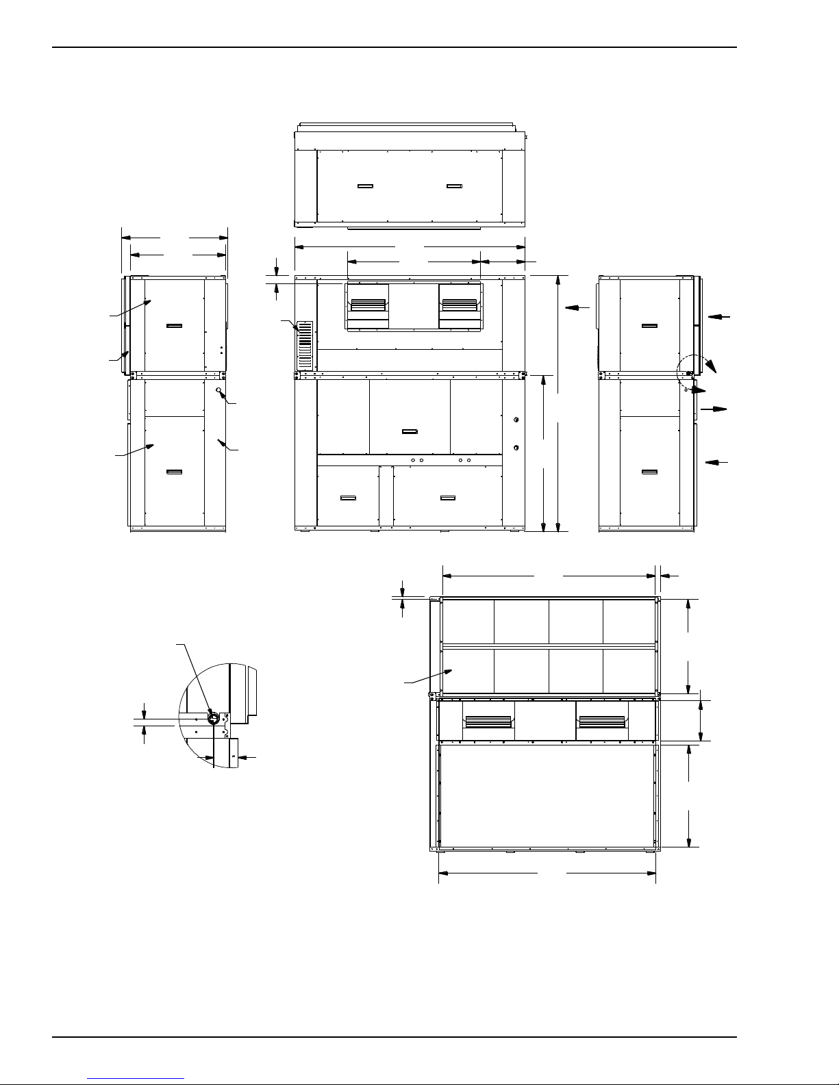
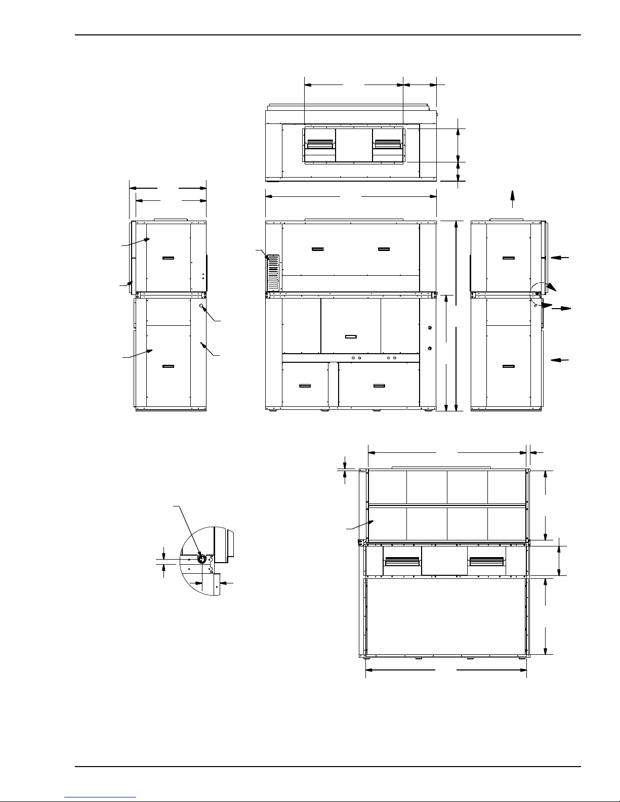
APPENDIX A: DIMENSIONAL DRAWINGS
DETAIL D
SCALE 0.1 : 1
D
FRONT VIEW
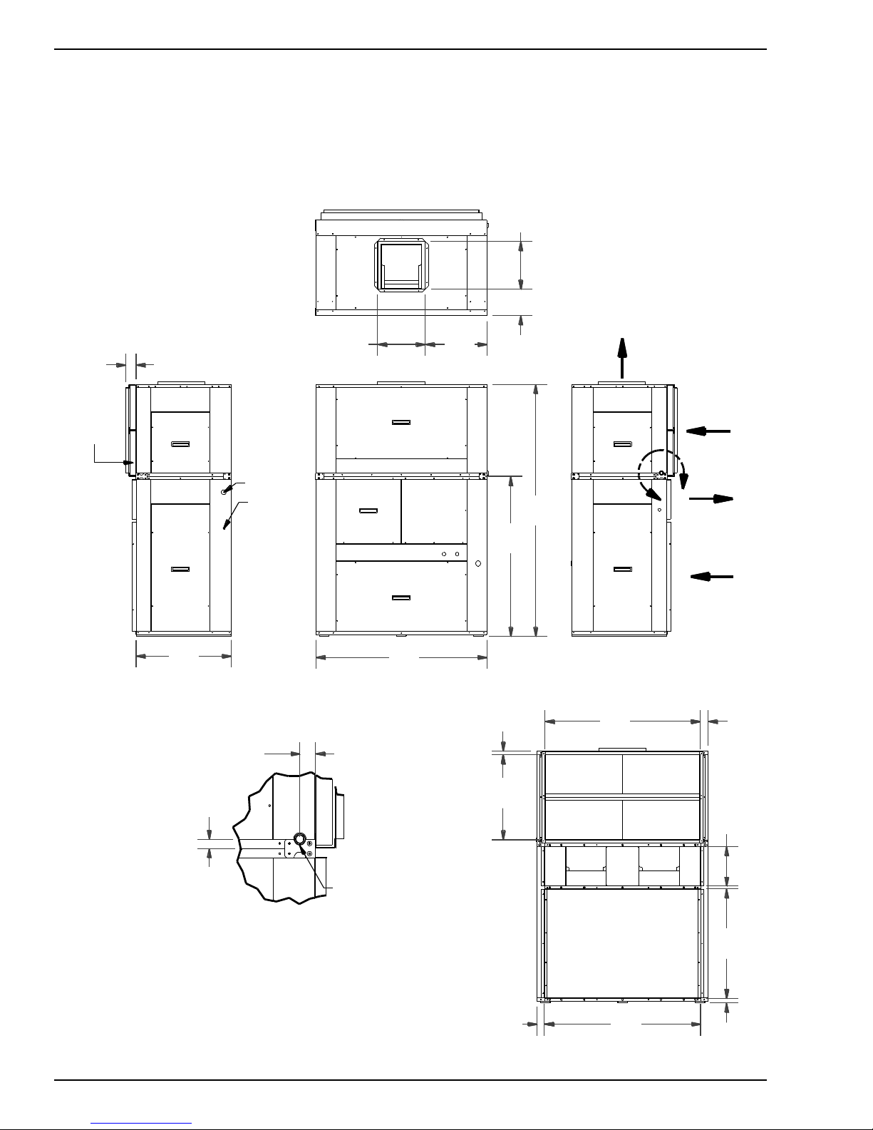
3/4" NPT
DRAIN
CONNECTION
BACK VIEW
29.00
52.00
7
6
.5
0
4
8
.6
3
47.50
1
2
.
0
0
3
3
.
1
8
14.50
ELECTR . POWER
CABLE ENTR ANCE
1.75
1.00
RETURN
AIR
CONDENSER
INTAKE
CONDENSER
DISCHARGE
SUPPLY
AIR
BACK RETURN,
VERTICAL DISCHARGE
ELECTR ICAL BOX
ACCESS PANEL
CON DENSER ACCESS PANEL
EVAPORATOR ACCESS PANEL
FILTER ACCESS
(BOTH SIDES)
LOW VOLTAGE
CON NECTION
5 TON VERTICAL A/C UNIT
DIMENSIONAL DATA
NOTE: DIMENSION TOLERANCE IS 1/16"
1
4
.5
0
47.13
2
5
.
8
8
3.12
EVAPORATOR
FAN DR IVE
ACCESS PANEL
CON DENSER
FAN DR IVE
ACCESS PANEL
8
.0
0
1
.0
0
1
.
5
0
2.25
2.44
18.75
DSV060B DIMENSIONAL DATA – TOP DISCHARGE
FORM 145.29-IOM2 (814)
26 JOHNSON CONTROLS
Page 27
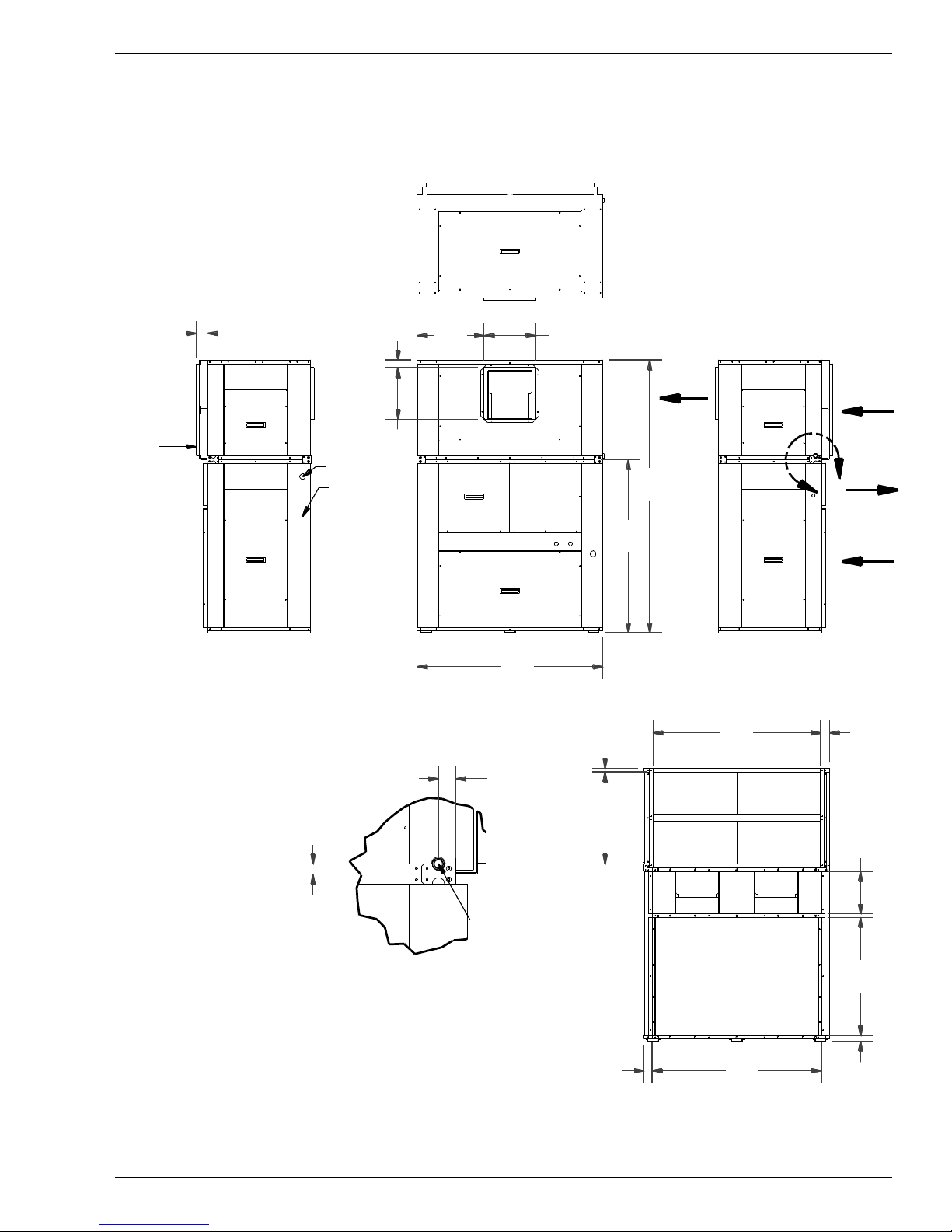
DSV060B DIMENSIONAL DATA – FRONT DISCHARGE
DETAIL F
SCALE 0.1 : 1
F
FRONT VIEW
3/4" NPT
DRAIN
CONNECTION
BACK VIEW
RETURN
AIR
CONDENSER
INTAKE
CONDENSER
DISCHARGE
SUPPLY
AIR
BACK RETURN,
FRONT DISCHARGE
ELECTRICAL BOX
ACCESS PANEL
CONDENSER ACCESS PANEL
FILTER ACCESS
(BOTH SIDES)
1
4
.
5
0
14.50
1
.0
0
1.75
52.00
7
6
.
5
0
1
2
.
0
0
3
3
.
1
8
47.50
4
8
.6
3
5 TON VERTICAL A/C UNIT
DIMENSIONAL DATA
CONDENSER
FAN DRIVE
ACCESS PANEL
EVAPORATOR
FAN DRIVE
ACCESS PANEL
47.13
2
5
.
8
8
1
.
5
0
1
.
0
0
2
.
1
3
3.12
ELECTR. POWER
CABLE ENTRANCE
LOW VOLTAGE
CONNECTION
NOTE: DIMENSION TOLERANCE IS 1/16"
2.44
2.25
18.75
FORM 145.29-IOM2 (814)
JOHNSON CONTROLS 27
Page 28

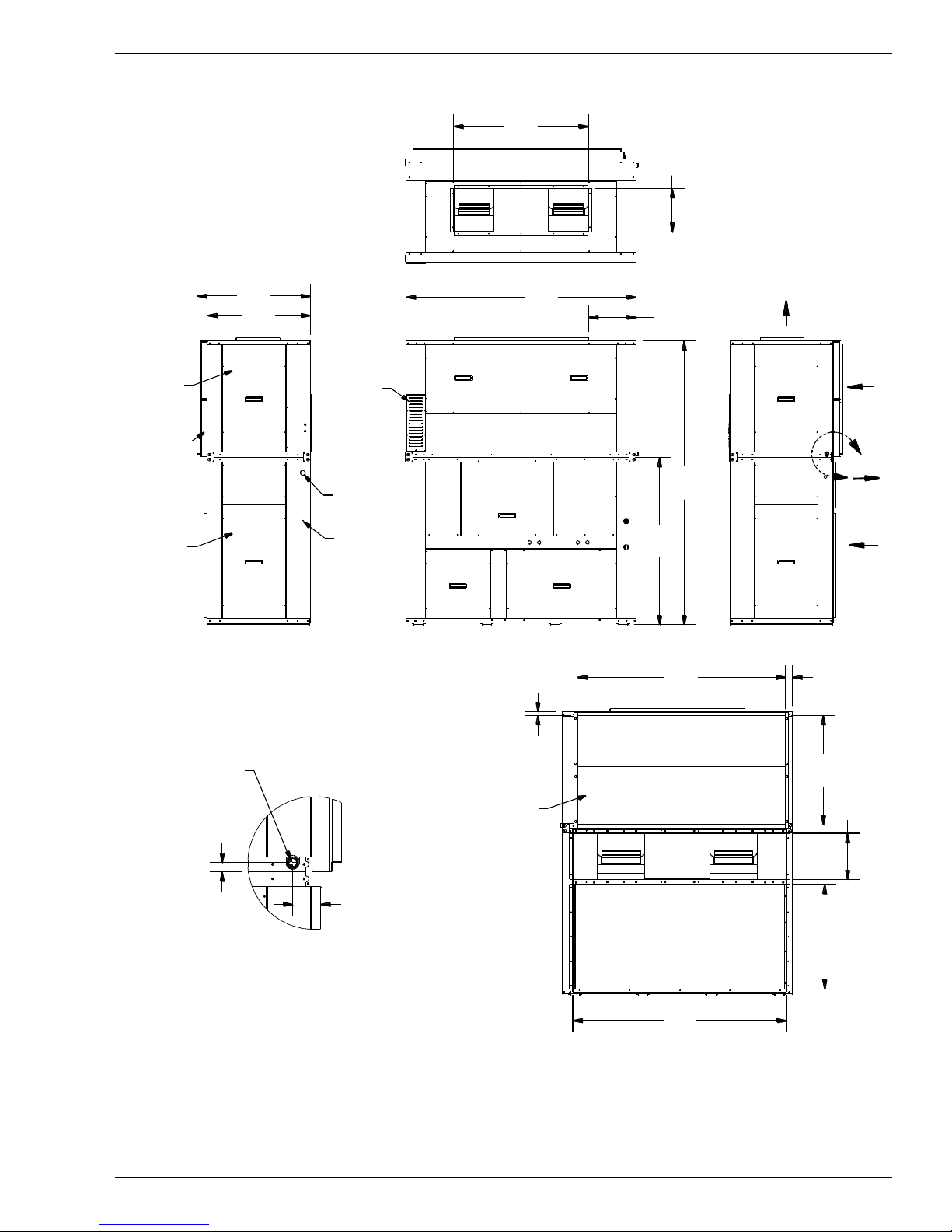
DSV096B & DSV120B DIMENSIONAL DATA – FRONT DISCHARGE
DETAIL A
A
ELECTRICAL BOX
ACCESS PANEL
COMPRESSOR
ACCESS PANEL
CONDENSER
INTAKE
CONDENSER
DISCHARGE
RETURN
AIR
10 TON VERTICAL A/C UNIT
DIMENSIONAL DATA
REAR RETURN,
FRONT DISCHARGE
FRONT VIEW
BACK VIEW
SUPPLY
AIR
NOTE: DIMENSION TOLERANCE IS 1/16"
2.88
0
.
9
3
3/4" NPT DRAIN
CONNECTION
71.50
41.88
1
3
.
6
9
8
8
.
1
3
2
.
7
5
14.81
5
2
.
0
6
32.00
36.06
EVAPORATOR
BLOWER DRIVE
ACCESS DOOR
FILTER ACCESS
(BOTH SIDES)
POWER SUPPLY
CABLE ENTRANCE
LOW VOLTAGE
CONNECTION
VFD LOCATION
(OPTIONAL)
CONDENSER
BLOWER DRIVE
ACCESS DOOR
64.63
3
4
.
1
3
3
2
.
5
0
1
4
.
3
1
1
.
0
0
2.20
66.50
FILTER
FORM 145.29-IOM2 (814)
28 JOHNSON CONTROLS
Page 29
DSV096B & DSV120B DIMENSIONAL DATA - TOP DISCHARGE
DETAIL A
A
10 TON VERTICAL A/C UNIT
DIMENSIONAL DATA
REAR RETURN,
TOP DISCHARGE
CONDENSER
DISCHARGE
RETURN
AIR
CONDENSER
INTAKE
COMPRESSOR
ACCESS PANEL
ELECTRICAL BOX
ACCESS PANEL
FRONT VIEW
BACK VIEW
NOTE: DIMENSION TOLERANCE IS 1/16"
71.50
41.88
1
3
.
6
9
14.81
8
8
.
1
3
5
2
.
0
6
32.00
35.13
SUPPLY
AIR
EVAPORATOR
BLOWER DRIVE
ACCESS DOOR
FILTER ACCESS
(BOTH SIDES)
POWER SUPPLY
CABLE ENTRANCE
LOW VOLTAGE
CONNECTION
CONDENSER
BLOWER DRIVE
ACCESS DOOR
VFD LOCATION
(OPTIONAL)
64.63
3
4
.
1
3
1
.
0
0
2.20
3
2
.
5
0
1
4
.
3
1
66.50
FILTER
2.88
0
.
9
3
3/4" NPT DRAIN
CONNECTION
FORM 145.29-IOM2 (814)
JOHNSON CONTROLS 29
Page 30
DSV144B & DSV180B DIMENSIONAL DATA - FRONT DISCHARGE
DETAIL A
A
FRONT VIEW
BACK VIEW
ELECTRICAL BOX
ACCESS PANEL
COMPRESSOR
ACCESS PANEL
CONDENSER
DISCHARGE
CONDENSER
INTAKE
RETURN
AIR
SUPPLY
AIR
12/15 TON VERTICAL A/C UNIT
DIMENSIONAL DATA
REAR RETURN,
FRONT DISCHARGE
NOTE: DIMENSION TOLERANCE IS 1/16"
82.50
47.63
34.00
38.06
15.97
9
1
.
6
3
5
5
.
8
8
2
.
8
8
EVAPORATOR
BLOWER DRIVE
ACCESS DOOR
FILTER ACCESS
(BOTH SIDES)
POWER SUPPLY
CABLE ENTRANCE
LOW VOLTAGE
CONN ECTION
2.88
0
.
8
0
3/4" NPT DRAIN
CONNECTION
76.13
3
3
.
6
3
1.97
1
.
0
0
1
4
.
3
1
3
6
.
6
9
77.63
VFD LOCATION
(OPTIONAL)
COND ENSER
BLOWER DRIVE
ACCESS DOOR
FILTER
FORM 145.29-IOM2 (814)
30 JOHNSON CONTROLS
Page 31
DSV144B & DSV180B DIMENSIONAL DATA - TOP DISCHARGE
DETAIL A
A
ELECTRICAL BOX
ACCESS PANEL
COMPRESSOR
ACCESS PANEL
CONDENSER
INTAKE
CONDENSER
DISCHARGE
RETURN
AIR
12/15 TON VERTICAL A/C UNIT
DIMENSIONAL DATA
REAR RETURN,
TOP DISCHARGE
FRONT VIEW
BACK VIEW
SUPPLY
AIR
NOTE: DIMENSION TOLERANCE IS 1/16"
82.50
47.63
1
6
.
1
3
9
.
2
5
16.00
9
1
.
6
3
5
5
.
8
8
34.00
37.13
EVAPORATOR
BLOWER DRIVE
ACCESS DOOR
FILTER ACCESS
(BOTH SIDES)
CONDENSER
BLOWER DRIVE
ACCESS DOOR
VFD LOCATION
(OPTIONAL)
POWER SUPPLY
CABLE ENTRANCE
LOW VOLTAGE
CONNECTION
76.13
3
3
.
6
3
3
6
.
6
9
1
4
.
3
1
1.97
1
.
0
0
2.88
0
.
8
0
3/4" NPT DRAIN
CONNECTION
77.63
FILTER
FORM 145.29-IOM2 (814)
JOHNSON CONTROLS 31
Page 32

DSV240B DIMENSIONAL DATA - FRONT DISCHARGE
DETAIL A
A
FRONT VIEW
BACK VIEW
ELECTRICAL BOX
ACCESS PANEL
COMPRESSOR
ACCESS PANEL
CONDENSER
DISCHARGE
CONDENSER
INTAKE
RETURN
AIR
SUPPLY
AIR
20 TON VERTICAL A/C UNIT
DIMENSIONAL DATA
REAR RETURN,
FRONT DISCHARGE
NOTE: DIMENSION TOLERANCE IS 1/16"
57.44
90.50
14.50
6
0
.
6
9
1
0
2
.
0
6
2
.
8
8
1
6
.
1
3
37.06
EVAPORATOR
BLOWER DRIVE
ACCESS PANEL
FILTER ACCESS
(BOTH SIDES)
CONDENSER
BLOWER DRIVE
ACCESS PANEL
POWER SUPPLY
CABLE ENTRANCE
LOW VOLTAGE
CONNECTION
85.633.19
4
2
.
6
9
1
3
.
0
6
84.13 1.97
3
8
.
3
8
1
.
5
0
1
.
3
8
2
.
0
6
1.88
0
.
8
0
3/4" NPT DRAIN
CONNECTION
VFD LOCATION
(OPTIONAL)
3
4
.
0
0
FILTER
FORM 145.29-IOM2 (814)
32 JOHNSON CONTROLS
Page 33

DSV240B DIMENSIONAL DATA - TOP DISCHARGE
DETAIL A
A
ELECTRICAL BOX
ACCESS PANEL
COMPRESSOR
ACCESS PANEL
CONDENSER
INTAKE
CONDENSER
DISCHARGE
RETURN
AIR
20 TON VERTICAL A/C UNIT
DIMENSIONAL DATA
REAR RETURN,
TOP DISCHARGE
FRONT VIEW
BACK VIEW
SUPPLY
AIR
NOTE: DIMENSION TOLERANCE IS 1/16"
90.50
14.56
6
0
.
6
9
1
0
2
.
0
6
0
.
9
4
34.00
9.38
EVAPORATOR
BLOWER DRIVE
ACCESS PANEL
FILTER ACCESS
(BOTH SIDE)
CONDENSER
BLOWER DRIVE
ACCESS PANEL
POWER SUPPLY
CABLE ENTRANCE
VFD LOCATION
(OPTIONAL)
LOW VOLTAGE
CONNECTION
1.88
0
.
8
0
3/4" NPT DRAIN
CONNECTION
1
6
.
1
3
57.44
84.13 1.97
1
3
.
0
6
4
2
.
6
9
2
.
0
6
85.633.20
3
8
.
3
8
2
.
4
4
1
.
3
8
FILTER
37.06
FORM 145.29-IOM2 (814)
JOHNSON CONTROLS 33
Page 34

DSV300B DIMENSIONAL DATA - FRONT DISCHARGE
DETAIL A
A
FRONT VIEW
BACK VIEW
ELECTRICAL BOX
ACCESS PANEL
COMPRESSOR
ACCESS PANEL
CONDENSER
DISCHARGE
CONDENSER
INTAKE
RETURN
AIR
SUPPLY
AIR
25 TON VERTICAL A/C UNIT
DIMENSIONAL DATA
REAR RETURN,
FRONT DISCHARGE
NOTE: DIMENSION TOLERANCE IS 1/16"
102.13 2.00
4
2
.
3
8
1
.
2
5
1
.
5
0
1
3
.
0
6
4
8
.
1
7
2
.
0
6
103.633.19
FILTER
108.50
77.63 17.44
1
1
0
.
0
6
6
4
.
6
9
1
6
.
1
3
VFD LOCATION
(OPTIONAL)
EVAPORATOR
BLOWER DRIVE
ACCESS DOOR
FILTER ACCESS
(BOTH SIDES)
CONDENSER
BLOWER DRIVE
ACCESS DOOR
POWER SUPPLY
CABLE ENTRANCE
LOW VOLTAGE
CONNECTION
2.88
0
.
8
0
3/4" NPT DRAIN
CONNECTION
34.00
38.00
3
.
1
2
FORM 145.29-IOM2 (814)
34 JOHNSON CONTROLS
Page 35

DSV300B DIMENSIONAL DATA - TOP DISCHARGE
DETAIL A
A
ELECTRICAL BOX
ACCESS PANEL
COMPRESSOR
ACCESS PANEL
CONDENSER
INTAKE
CONDENSER
DISCHARGE
RETURN
AIR
25 TON VERTICAL A/C UNIT
DIMENSIONAL DATA
REAR RETURN,
TOP DISCHARGE
FRONT VIEW
BACK VIEW
SUPPLY
AIR
NOTE: DIMENSION TOLERANCE IS 1/16"
103.633.19
2
.
0
6
4
8
.
1
9
1
3
.
0
6
102.13 2.00
1
.
2
5
4
2
.
3
8
1
.
3
8
FILTER
108.50
77.63
1
6
.
1
3
1
1
0
.
0
6
6
4
.
6
9
0
.
9
4
34.00
37.06
EVAPORATOR
BLOWER DRIVE
ACCESS D OOR
FILTER ACCESS
(BOTH SIDES)
CON DENSER
BLOWER DRIVE
ACCESS D OOR
POWER SUPPLY
CABLE ENTRANC E
LOW VOLTAGE
CON NECTION
VFD LOCATION
(OPTIONAL)
2.88
0
.
8
0
3/4" NPT DR AIN
CON NECTION
17.44
9
.
8
8
FORM 145.29-IOM2 (814)
JOHNSON CONTROLS 35
Page 36

APPENDIX B: TYPICAL SERVICE CLEARANCES
24 In. Side
42 In. Front
REAR RETURN,
FRONT DISCHARGE
ELECTRICAL BOX
ACCESS PANEL
COMPRESSOR
ACCESS PANEL
FORM 145.29-IOM2 (814)
36 JOHNSON CONTROLS
Page 37

APPENDIX C: TYPICAL UNIT WIRING SCHEMATICS
FORM 145.29-IOM2 (814)
JOHNSON CONTROLS 37
Page 38

FORM 145.29-IOM2 (814)
38 JOHNSON CONTROLS
Page 39

FORM 145.29-IOM2 (814)
JOHNSON CONTROLS 39
Page 40

FORM 145.29-IOM2 (814)
40 JOHNSON CONTROLS
Page 41

FORM 145.29-IOM2 (814)
JOHNSON CONTROLS 41
Page 42
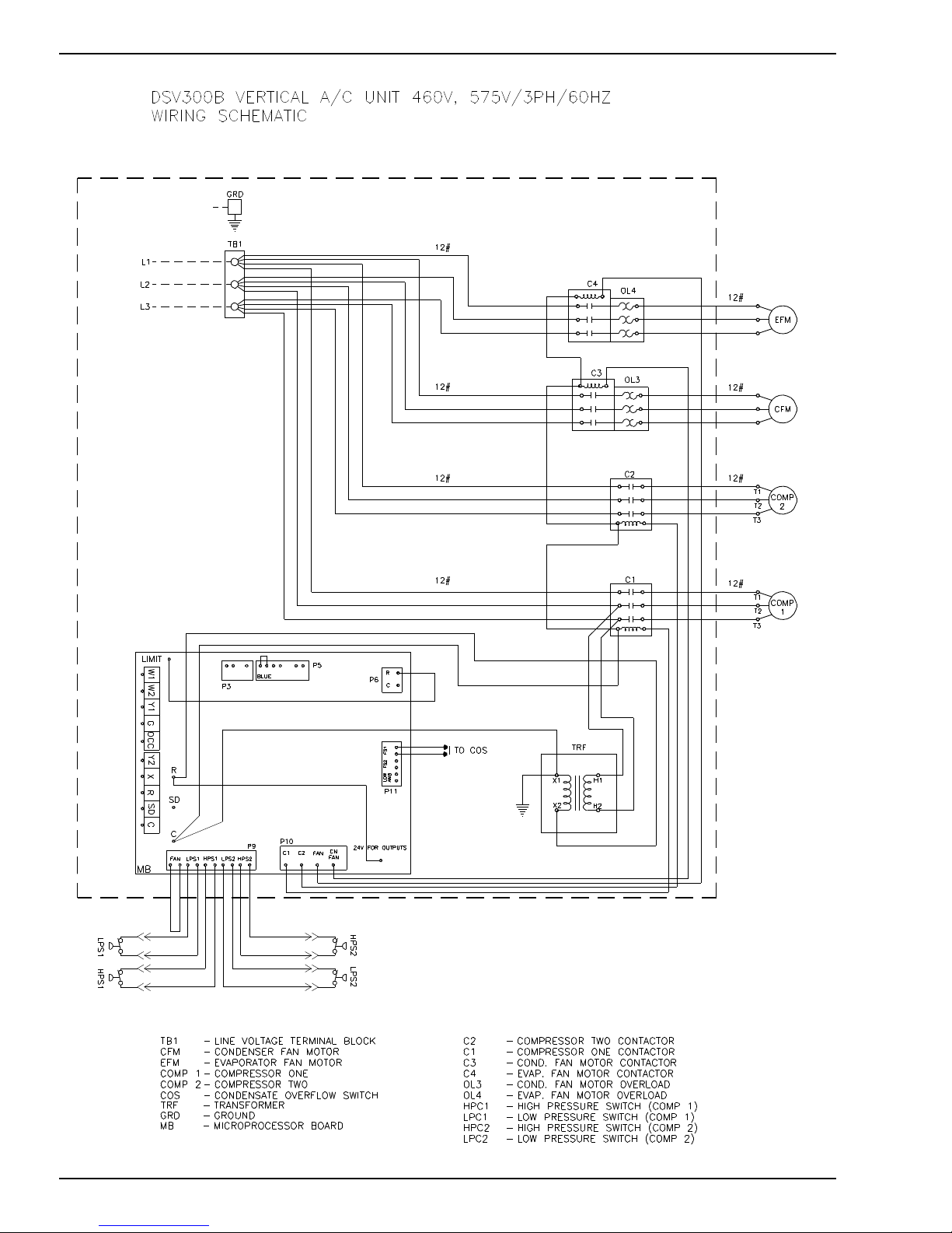
FORM 145.29-IOM2 (814)
42 JOHNSON CONTROLS
Page 43
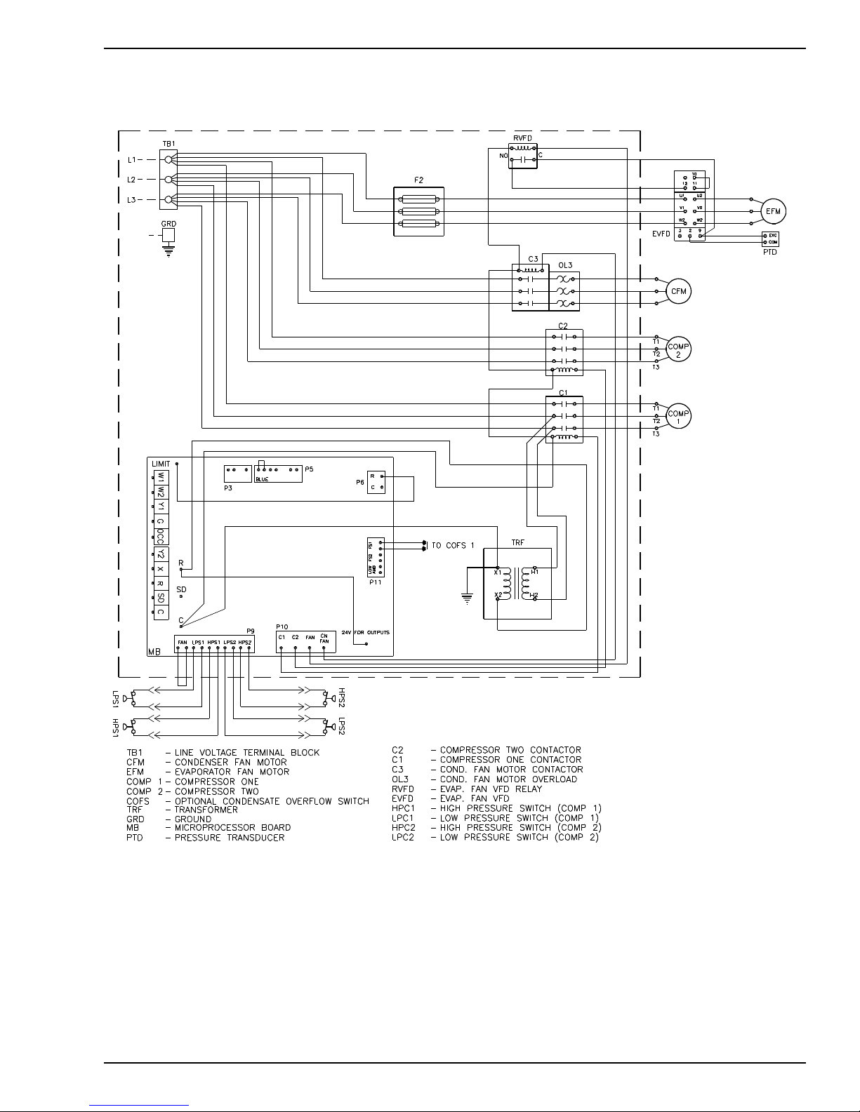
TYPICAL VFD UNIT WIRING SCHEMATIC
FORM 145.29-IOM2 (814)
JOHNSON CONTROLS 43
Page 44

TYPICAL ECONOMIZER WIRING SCHEMATICS (SINGLE AND DUAL STAGE SHOWN)
DSV060B
Economizer Schematic
DSV096B-DSV300B
Economizer Schematic
FORM 145.29-IOM2 (814)
44 JOHNSON CONTROLS
Page 45

FORM 145.29-IOM2 (814)
NOTES
JOHNSON CONTROLS 45
Page 46

FORM 145.29-IOM2 (814)
46 JOHNSON CONTROLS
Page 47
FORM 145.29-IOM2 (814)
R-410A QUICK REFERENCE GUIDE
Refer to Installation Instructions for specific installation requirements.
R-410A Refrigerant operates at 50 - 70 percent higher pressures than R-22. Be sure that servicing
equipment and replacement components are designed to operate with R-410A.
R-410A Refrigerant cylinders are rose colored.
Recovery cylinder service pressure rating must be 400 psig. DOT 4BA400 or DOT BW400.
Recovery equipment must be rated for R-410A.
Do not use R-410A service equipment on R-22 systems. All hoses, gages, recovery cylinders,
charging cylinders and recovery equipment must be dedicated for use on R-410A systems only.
Manifold sets must be at least 700 psig high side, and 180 psig low side, with 550 psig retard.
All hoses must have a service pressure rating of 800 psig.
Leak detectors, must be designed to detect HFC refrigerants.
Systems must be charged with refrigerant. Use a commercial type metering device in the manifold
hose.
R-410A can only be used with POE type oils.
POE type oils rapidly absorb moisture from the atmosphere.
Vacuum pumps will not remove moisture from POE type oils.
Do not use liquid line driers with a rated working pressure rating less than 600 psig.
Do not install suction line driers in the liquid line.
A liquid line drier is required on every unit.
Do not use an R-22 TXV. If a TXV is to be used, it must be an R-410A TXV.
Never open system to atmosphere when under vacuum.
If system must be opened for service, evacuate system then break the vacuum with dry nitrogen and
replace filter driers.
JOHNSON CONTROLS 47
Page 48

P.O. Box 1592, York, Pennsylvania USA 17405-1592 800-861-1001 Subject to change without notice. Printed in USA
Copyright © by Johnson Controls 2014 www.johnsoncontrols.com ALL RIGHTS RESERVED
Form 145.29-ICOM2 (814)
Issue Date: August 25, 2014
Supersedes: 145.29-ICOM2 (812)
 Loading...