

Page 1

Setra Systems
Operating Instructions
DPT267 and DPT267MR Series Low Pressure Transducers
1. GENERAL INFORMATION
Every Model 267 and Model 267MR (Multi-Range) has been tested and calibrated before shipment.
Specific performance specifications are listed on Page 9 of this Guide.
The Model 267 is single range only. The Model 267MR has field selectable range capability. The
267MR is factory calibrated for the highest pressure range. The range label on the cover of the unit
indicates the factory-calibrated range. Should the 267MR be re-ranged in the field, the Multi-Range
labels are included.
Setra Systems 267 and 267MR pressure transducers sense differential or gauge (static) pressure and
convert this pressure difference to a proportional high level analog output for both unidirectional and
bidirectional pressure ranges. Two output versions are offered: A voltage output, configurable: 0 to 5
VDC or 0 to 10 VDC, and a current output: 4 to 20 mA
Sections 1 through 4 and 7 through 9 of this Guide apply to both Model 267 and 267MR. Section 5
refers to the Model 267 only. Section 6 refers to the Model 267MR only.
2.0 MECHANICAL INSTALLATION
2.1 Media Compatibility
Model 267 and 267MR transducers are designed to be used with air or non-conducting gases.
Use with liquids or corrosive gases will damage the unit.
2.2 Environment
The operating temperature limits of the 267 and 267MR are as follows:
Operating Temperature 0°F to +150°F (-18°C to +65°C)
Compensated Temperature Range +40°F to +150°F (+5°C to +65°C)
2.3 Pressure Fittings
The Model 267 and 267MR can be supplied with three different pressure fitting configurations:
1. 3/16” O.D. Barbed Brass Pressure Fittings – Typically installed with 1/4” push-on tubing.
2. 1/4” NPT Brass Pressure Fittings – Typically installed with mating NPT male fitting.
3. Static Pressure Probe – Installed on the duct by drilling a 7/16” hole in the duct at the desired
mounting location, inserting the pressure probe into the duct, and mounting the 267 onto the duct
with the mounting tabs.
For the 3/16” O.D. and 1/4” NPT pressure fittings, both the positive (high) pressure port and the
reference (low) pressure port are located on the bottom of the unit, labeled “HIGH” and “LOW”
respectively. For best results (shortest response times), 3/16” I.D. tubing is suggested for tubing
lengths up to 100 feet long, 1/4” I.D. for tubing lengths up to 300 feet, and 3/8” I.D. for tubing lengths
up to 900 feet.
The static pressure probe is the positive (high) pressure port located on the back of the unit. The
reference (low) pressure port is located on the bottom of the unit and can be used for differential pressure
measurements.
3.0 ELECTRICAL INSTALLATION
Wiring is through a 1/2” conduit opening or an optional PG-9 or PG-13-5 or 9-pin D-sub connector. (See
Section 3.2 for instructions on wiring the 9 pin D-sub connector.) Both current and voltage output units are
reverse wiring protected.
Page 2
3.1 Voltage Output Units – 1/2” Conduit Opening, PG-9 or PG-13.5 Electrical Termination
(267MR version only)
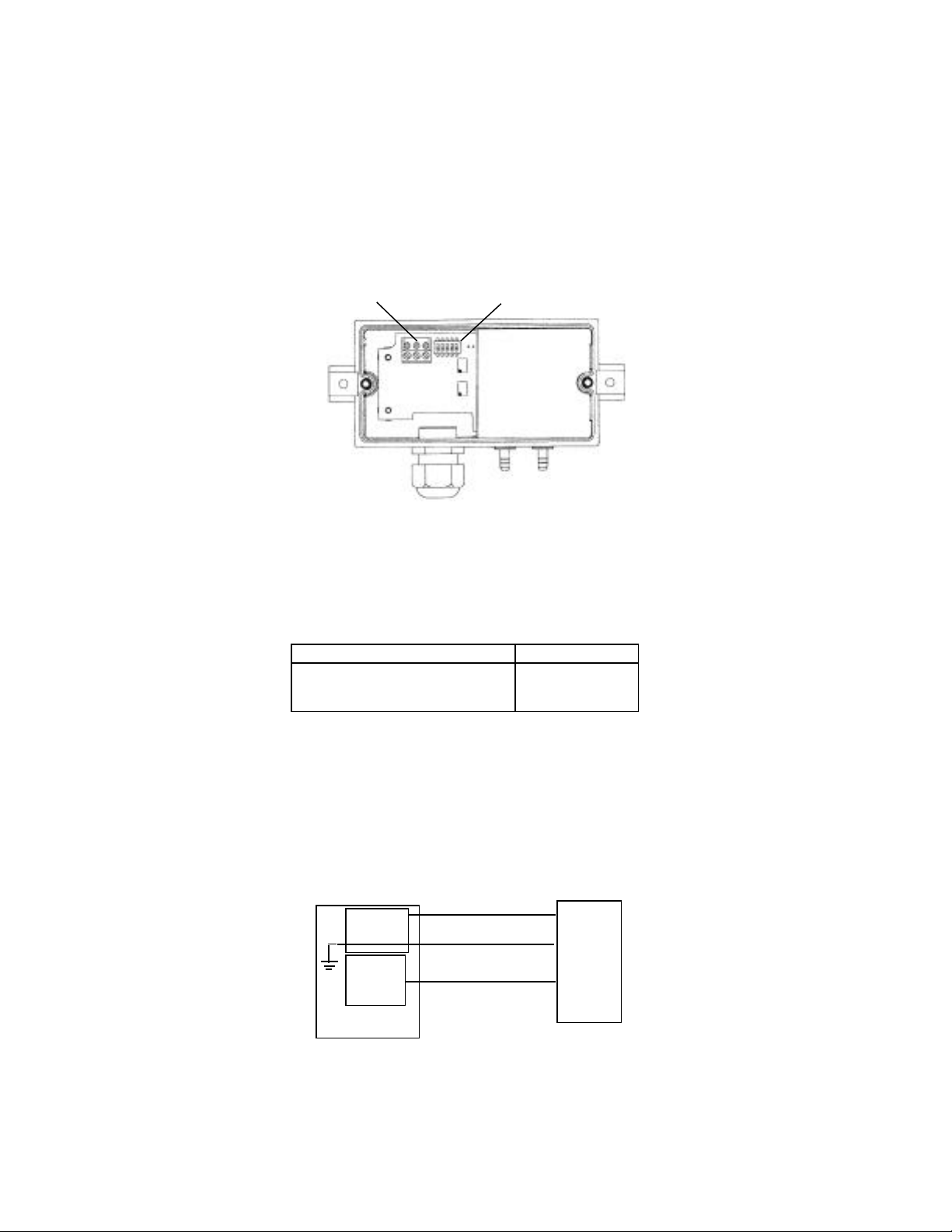
Wiring terminations are identified on the circuti board below the terminal strip (see Section 3.1 for
voltage output units or Section 3.3 for current units). To access the terminal strip, turn the screws on
top of the case counter clockwise until the cover can be removed. The screws are captured and will be
secured in the top of the case.
Electrical
Range Select Switches
Connections
Diagram 1
The Model 267 and 267MR voltage output is a 3-wire circuit, with three terminals available for wiring
(see Diagram 1). The -Excitation and -Output are commoned on the circuit (see Diagram 2). The
excitation/output specifications are:
Excitation Output
9 to 30 VAC / 11.5 to 42 VDC 0 to 5 VDC
12 to 30 VAC / 13 to 42 VDC 0 to 10 VDC
The 267MR has field selectable 0-5 or 0-10 VDC output. (See Section 6.0 for switch settings to determine
whether the voltage output is set to 0-5 or 0-10 VDC.) The 267 has either a 0-5 VDC or 0-10 VDC
output, calibrated at the factory.
Voltage Circuit Diagram
Power
Supply
Readout or
DAS
Diagram 2
+EXC Connected to positive terminal of DC or AC Power Supply
GND Connect as the reference port for power supply and output signal
+SIG Connect to positive terminal of Control or Pressure Monitor
+EXC
GND
+SIG
Model
267MR
Page 3
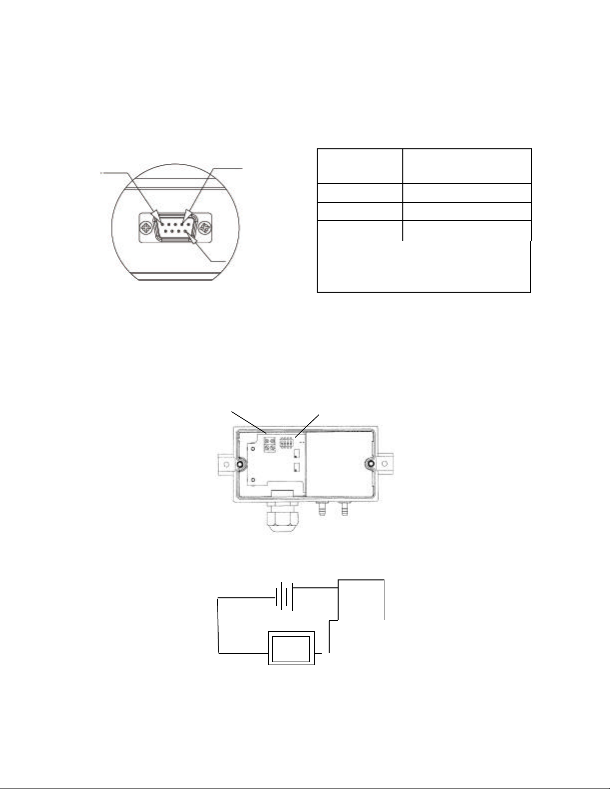
3.2 Voltage Output Units – 9 pin D-sub Connector Electrical Termination
Device
The Model 267 and 267MR voltage output is a 3-wire circuit with three pins available for wiring (see
Diagram 3). The voltage output pin designations are shows in Diagram 4.
Diagram 4
PIN 1
PIN 4
CONNECTION 9 pin D-sub Connector
Electrical Termination
+EXCITATION 4
+OUTPUT 1
COMMON 9
Excitation Output
PIN 9
- EXC
9 to 30 VAC/11.5 to 42 VDC 0 to 5 VDC
12 to 30 VAC/13 to 42 VDC 0 to 10 VDC
Diagram 3
3.3 Current Output Units 1/2” Conduit Opening, PG-9 or Pg-13.5 Electrical Termination
The Model 267 and 267MR is a two-wire loop-powered 4 to 20mA current output unit (see Diagram
5). The current flows into +EXC. terminal and returns back to the power supply through the -EXC.
Terminal (see Diagram 6). The power supply must be a DC voltage source with a voltage range
between 9 and 30 measured between terminal +EXC. and -EXC. The unit is calibrated with a 24 VDC
loop supply voltage and a 250 ohm load.
Electrical
Connections
Range Select Switches
(267MR version only)
Diagram 5
9 to 30 VDC
Current
Monitoring
Diagram 6
+
-
267MR
Page 4

3.4 Current Output Units – 9 pin D-sub Connector electrical Termination
The Model 267 and 267MR is a two wire loop-powered 4 to 20 mA current output unit (see Diagram
6). The current flows into +EXC. Pin4 (+EXC.) and returns back to the power supply through
Pin 9 (-EXC) (see Diagram 7). The power supply must be a DC voltage source with a voltage range
between 9 and 30 measured between Pin 4 and Pin 9 (-EXC.). The unit is calibrated with a 24 VDC
loop supply voltage and a 250ohm load. The current output 9 pin D-sub connector pin designations are
shown in Diagram 8.
PIN 1
PIN 1
Diagram 7 Diagram 8
3.5 4-20 mA Circuit Diagram
Minimum Supply Voltage (VDC) = 9 + 0.02 x (resistance of receiver plus line)
Maximum Supply Voltage (VDC) = 30 + 0.004 x (resistance of receiver plus line)
If the current loop has a current limiter, threshold should be adjusted to 35 mA minimum
(see Diagram 9).
Loop Resistance for 4 to 20 mA Current Tranducers
PIN 4
PIN 4
PIN 9
- EXC
Loop Power Supply
vs.
CONNECTION 9 pin D-sub Connector
Electrical Termination
+EXCITATION 4
+OUTPUT 9
Loop Resistance (Ohms)
800
Operating
0
9
Loop Supply Voltage (VDC)
Diagram 9
Range
30
Page 5

3.6 EMC Certification
This product complies with EN61326 Electrical Equipment for Measurement Control and Laboratory
use – EMC Requirements for Minimum Requirements and Industrial Locations. Special caution should
be taken to meet Standard EN61000-4-5: 1995 Surge Immunity if any of the following conditions apply
to the installation: the product is installed outside; all or any part of the cable is exposed to the outside;
the cable is greater than 30 meters in length. In order to meet the CE Surge Immunity requirements, the
following conditions must be followed during installation:
1. Shielded cable must be used, and the shield must be tied to earth ground (not power supply
ground) on at least one end of the cable shield/drain wire. The shield must be maintained all
the way from sensor to the power supply.
2. If unshielded cable is used, an earth grounded metal conduit should be used to replace the
shielded cable.
3. For a sensor with a metal body or enclosure, the body/enclosure must be grounded to earth.
4. If a protective metal housing is used, the housing must be able to withstand at least 2 kV from
the housing to earth ground without damaging the circuit.
4.0 CALIBRATION
The 267 and 267MR transducer is factory calibrated and should require no field adjustment. Generally, the
mounting position will have a zero shift effect on ranges below 1” WC. Whenever possible, any zero and/or
span offsets should be corrected by software adjustment in the user’s control system. However, both zero
and span adjustments are accessible under the cover of the unit, below and to the right of the terminal strip.
The 267 and 267MR transducer is calibrated in the vertical position at the factory (mounting tabs vertical).
4.1 Voltage Output Zero Adjustment
While monitoring the voltage between the positive output (+SIG) and common (GND), and with both
pressure ports open to atmosphere, the zero may be adjusted by turning the zero adjustment screw. (See
Diagram 1 for location of zero adjustment.) Factory settings are:
Unidirectional Pressure Ranges Bidirectional Pressure Ranges
Zero Adjustment Output Zero Adjustment Output
0.05 VDC (±25 V) 0-5 VDC 2.5 VDC (±25 mV) 0-5 VDC
0.05 VDC (±50 V) 0-10 VDC 5 VDC (±50 mV) 0-10 VDC
4.2 Voltage Output Zero Adjustment (Complete the zero adjustment setting before setting span.)
Span of full scale output adjustments should only be performed by using an accurate pressure standard
(electronic manometer, digital pressure gauge, etc.), with at least comparable accuracy to the 267 or
267MR transducer (<±1% FS). With full range pressure applied to the high pressure port (reference port
open to atmosphere), the span may be adjusted by turning the Span adjustment screw. (See Diagram 1
for location of Span adjustment.) Factory settings are:
Unidirectional Pressure Ranges Bidirectional Pressure Ranges
Span Adjustment Output Zero Adjustment Output
5.0 VDC (±25 V) 0-5 VDC 2.5 VDC (±25 mV) 0-5 VDC
10 VDC (±50 V) 0-10 VDC 5 VDC (±50 mV) 0-10 VDC
Example 1: Unidirectional pressure range of 0 to 1” W.C. with 0 to 5 VDC output
Apply 1.00” W.C., adjust span to 5 VDC (—25 mV)
Example 2: Bidirectional pressure range of ±5” W.C. with 0 to 5 VDC output
Apply 5.00” W.C., adjust span to 5 VDC (±25 mV)
Page 6

4.3 Current Output Zero Adjustment
While monitoring the current output, and with both pressure ports open to atmosphere, the zero may be
adjusted by turning the zero adjustment screw. (See Diagram 5 for location of zero adjustment.) Factory
settings are:
Unidirectional Pressure Ranges Bidirectional Pressure Ranges
Zero Adjustment Output Zero Adjustment Output
4mA (0.08 mA) 4-20 mA 12 mA (0.08 mA) 4-20 mA
4.4 Current Output Span Adjustment
Span or full scale output adjustments should only be performed by using an accurate pressure standard
(electronic manometer, digital pressure gauge, etc.) with at least comparable accuracy to the 267 or
267MR transducer (<±1% full scale). With full range pressure applied to the high pressure port (reference
port open to atmosphere), the span may be adjusted by turning the SPAN adjustment screw. (See
Diagram 1 for location of Span adjustment.) Factory Settings are:
Unidirectional Pressure Ranges Bidirectional Pressure Ranges
Span Adjustment Output Zero Adjustment Output
20mA (0.08 mA) 4-20 mA 20 mA (0.08 mA) 4-20 mA
Example 1: Unidirectional pressure range of 0 to 1” W.C. with 4 to 20 mA output
Apply 1.00” W.C., adjust span to 20 mA (±0.08mA)
Example 2: Bi-directional pressure range of 5” W.C. with 4 to 20 mA output
Apply 5.00” W.C., adjust span to 20 mA (±0.08mA)
5.0 MODEL 267 OPTIONAL LCD DISPLAY
The 267MR is available with an optional 3-1/2 digit LCD display. The LCD is adjusted at the factory
prior to shipment. The LCD is connected to the zero and span adjustment potentiometers. Therefore,
adjustment of the zero and span according to Section 4 adjusts the LCD display.
6.0 Multi-Range Operation – Model 267MR only
The 267MR is re-rangeable by accessing the switches located internal to the transducer housing. To access
the “Dip” switches, remove the screws on the top of the case and lift off the cover. The “Dip” switches are
located on the electronics board as show in Diagrams 1 and 5. The voltage output version has 5 switches,
while the current version has 4. The location of these switches, “on” (up position) or “off” (down
position) determine what range has been selected. See Table 1 below for switch positions for in.W.C.
Multi-Range units are factory set to the highest range. As an example, an MR2 range is factory set to 0 to
1” W.C.
If it is a 0-5 VDC
output, the
switches are set:
To change the range
to 0 to 0.25 in.WC
with a 0-10 VDC
output change the
If the 267MR Range is re-configured from the factory calibration, place the correct range label (enclosed) on
the over label, over the area indicating the factory default range.
Notes: Voltage output is set based upon ordering code. See switch settings below to confirm voltage output.
Page 7
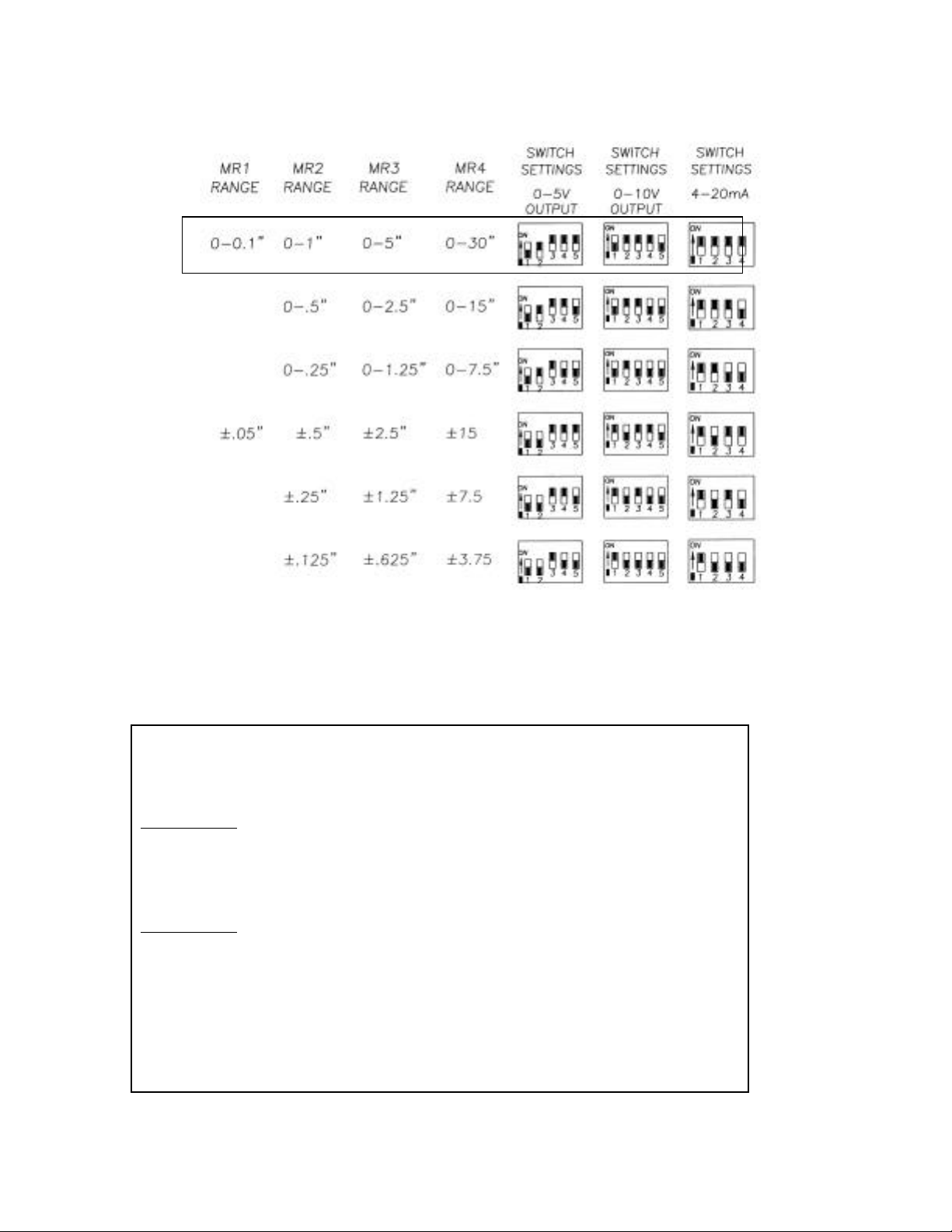
TABLE 1 RANGE SWITCHING INSTRUCTIONS FOR IN.WC
Factory Default Setting
7.0 MODEL 267 & 267MR PERFORMANCE SPECIFICATIONS
Accuracy RSS* (at constant temperature) ±1.0% FS
Non-Linearity, BFSL ±0.98% FS
Hysteresis 0.2% FS
Non-Repeatability 0.1% FS
*RSS of Non-Linearity, Non-Repeatability, and Hyseresis
Thermal Effects
Compensated Range °F (°C) +40 to +150 (+5 to +65
Zero/Span Shift %FS/°F (°C) 0.033 (0.06)
Maximum Line Pressure 10 psi in positive or negative
Overpressure 10 psi in positive or negative direction
Warm-up Shift ±0.1% FS Total
Position Effects
(Unit is factory calibrated at 0g effect in the vertical
position
Range Zero Offset (%FS/G)
0 to 0.1” W.C. 2.1
0 to 1” W.C. 0.22
0 to 5” W.C. 0.14
0 to 30” W.C. 0.06
 Loading...