

Page 1

Setra Systems
DPT 264 Series Low Pressure Transducers and Transmitters
Installation Guide
1.0 GENERAL INFORMATION
Every Model DPT264 has been tested and calibrated before shipment. Specific performance specifications are
shown on page 3 of this Guide.
Setra Systems DPT264 pressure transducers sense differential or gage (static) pressure and convert this pressure
difference to a proportional high level analog output for both unidirectional and bi-directional pressure ranges.
Two standard output versions are offered: A voltage output of 0 to 5 VDC or a current output of 4 to 20 mA.
2.0 MECHANICAL INSTALLATION
2.1Media Compatibility
Model DPT264 transducers are designed to be used with air or non-conducting gases. Use with liquids or
corrosive gases will dame the unit.
2.2 Environment
The operating temperature limits of the DPT264 are 0°F to +175°F (-18°C to +79°C)
The compensated temperature range is 0°F to +150°F (-18°C to +65°C).
2.3 Mounting
The DPT264 series is designed for mounting in either 2.75: snap-track or by using the four (4)
slots (suitable for #6 screws) that are provided on the plate. Optimum performance is obtained by isolating
the instrument from vibration and providing relatively clean, dry ambient air to the pressure ports.
Even though there is no flow through the DPT264, a filter is located in both the high and low-pressure ports
for use in extreme dust or moisture conditions.
In most cases, preferred installation is with the baseplate mounted vertically and located on a relatively flat
surface in a junction box or attached to a nearby beam. Easy field replacement is possible by removing
the single case screw that holds the black sensor/circuit housing to the baseplate and lifting the black
housing free. The baseplate remains mounted and can be used with the replacement unit’s black
sensor/circuit housing.
The axis most sensitive to vibration is the one perpendicular to the baseplate. Avoid mounting with
maximum vibration along this axis.
2.4 Pressure Fittings
The Model DPT264 is designed to be used with 3/16” I.D. push-on tubing. Both the positive (high) pressure
port and the reference (low) pressure port are located on the front of the unit, labeled “HIGH” and “LOW”
respectively. For best results (shortest response time), 3/16” I.D. tubing is suggested for tubing lengths up to
100 feet long, 1/4” I.D. for tubing lengths up to 300 feet, and 3/8” I.D. for tubing lengths up to 900 feet.
3.0 ELECTRICAL INSTALLATION
If the Model DPT264 is supplied with the optional Conduit Enclosure, access the electrical terminations by
removing the cover.
3.1 Voltage Output Units
The Model DPT264 voltage output is a 3-wire circuit, with three terminals available for wiring. These
terminals have the designation COM, EXC, and OUT (see Diagram 1). The power supply and signal
references are commoned on the circuit (see Diagram 2). The DPT264 voltage output can operate from 930 VDC excitation. The DPT264 has a 0-5 VDC output.
Page 2
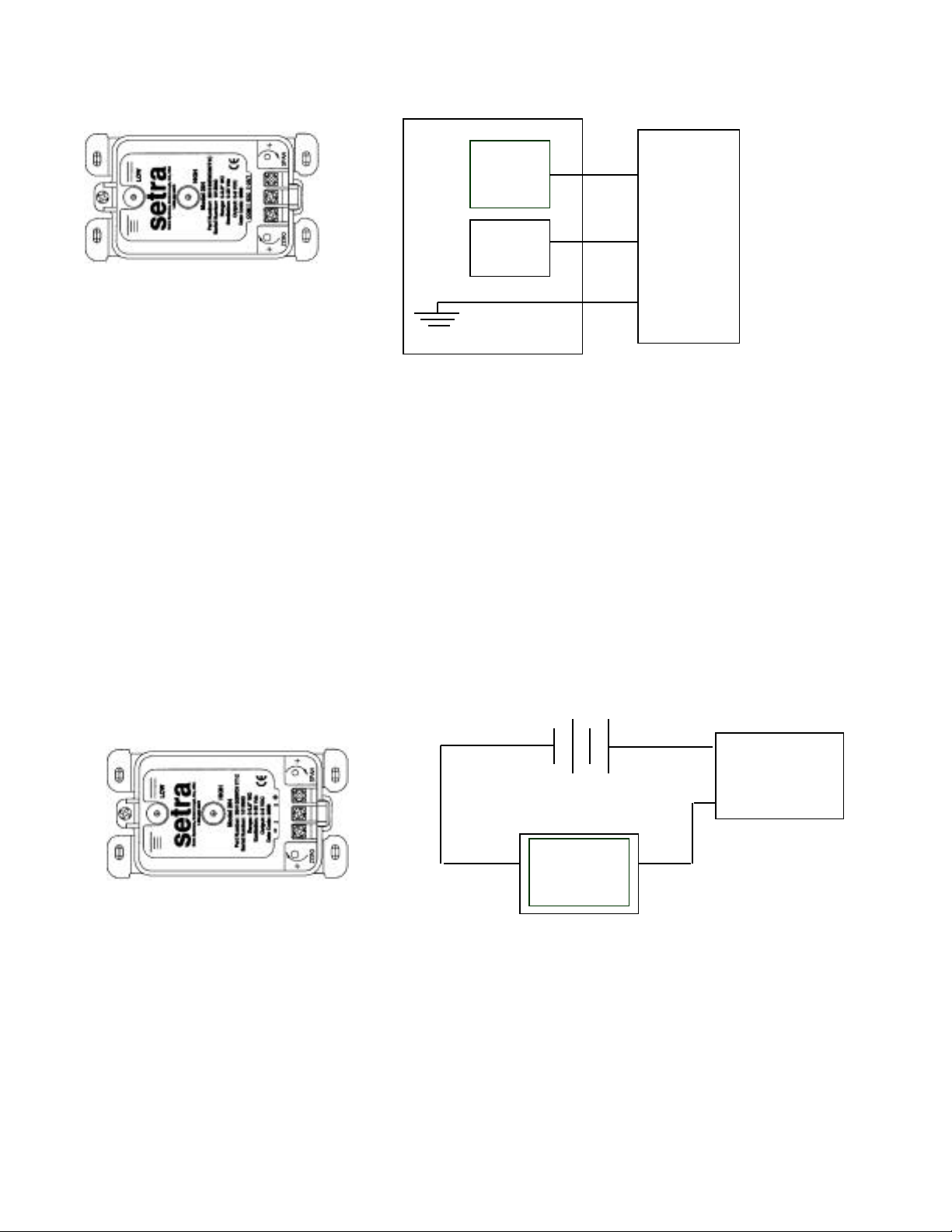
Voltage Circuit Diagram
Readout
or
DAS
Power
Supply
Diagram 1 Diagram 2
+EXC Connect to positive terminal of 9-30 VDC Power Supply
+OUT Connect to positive terminal of Control or Pressure Monitor
COM Connect as the reference for power supply and output signal
3.2 Current Output Units
The Model DPT264 is a two-wire loop-powered 4 to 20 mA current output unit and delivers rated current
into any external load of 0 to 800 ohms. These terminals have the designation of + and – (see Diagram 3).
The current flows into the + terminal and returns back to the power supply through the – terminal (see
Diagram 4). The power supply must be a DC voltage source with a voltage range between 9 and 30
measured between the + and – terminals. The unit is calibrated at the factory with a 24 VDC loop supply
voltage and a 250ohm load.
OUT
Model
DPT264
EXC
COM
Current Circuit Diagram
+
DPT264
9 to 20 VDC
Current
Monitoring
Device
Diagram 3 Diagram 4
4.0 CALIBRATION
The DPT264 transducer is factory calibrated and should require no field adjustment. Generally, the mounting
position will have a zero effect on ranges below 1” WC. Whenever possible, any zero and/or span offsets should be
corrected by software adjustment in the user’s control system. However, both the zero and span adjustments are
accessible either on the front of the unit or by removing the optional conduit enclosure. The DPT264 transducer is
calibrated in the vertical position at the factory.
–
Page 3

4.1 Voltage Output Zero Adjustment
While monitoring the voltage between the positive output (OUT) and common (COM), and with both
pressure ports open to atmosphere, the zero may be adjusted by turning the zero adjustment screw (see
Diagram 1 for location of the zero adjustment). For 0-5 VDC output units, the factory settings are 0.050 VDC
(±50 mV) for unidirectional pressure ranges and 2.5 VDC (±50 mV) for bi-directional pressure ranges.
Optional outputs are set at the same ±1% factory setting tolerance.
4.2 Voltage Output Span Adjustment (Complete the zero adjustment before setting span.)
Span or full-scale output adjustments should only be performed by using an accurate pressure standard
(electronic manometer, digital pressure gauge, etc.) with at least comparable accuracy to the DPT264
transducer (±1% full scale). With full range pressure applied to the high-pressure port (reference port open
to atmosphere), the span may be adjusted by turning the SPAN adjustment screw. (See Diagram 1 for
location of the SPAN adjustment.) For 0-5 VDC output units, the factory settings at full range pressure are
5.050 VDC (±50 mV) for unidirectional and bi-directional ranges.
4.3 Current Output Zero Adjustment
While monitoring the current output between the + and – terminals, and with both pressure ports open to
atmosphere, the zero may be adjusted by turning the zero adjustment screw. (See Diagram 3 for location of
zero adjustment.) The factory settings are 4 mA (0.16mA) for unidirectional pressure ranges and 12 mA
(0.16 mA) for bi-directional ranges.
4.4 Current Output Span Adjustment
Span of full-scale output adjustments should only be performed by using an accurate pressure standard
(electronic manometer, digital pressure gauge, etc.) with at least comparable accuracy to the DPT264
transducer (±1% FS). With full range pressure applied to the high-pressure port (reference port open to
atmosphere), the span may be adjusted by turning the SPAN adjustment screw. (See Diagram 3 for location
of SPAN adjustment.) The factory settings are 20 mA (0.16 mA) for unidirectional and bi-directional
pressure ranges.
5.0 MODEL DPT264 PERFORMANCE SPECIFICATIONS
Accuracy* ±1.0% FS Thermal Effects
(at Constant temperature) Compensated Range °F (°C) 0 to +150 (-18 to +65)
Non-Linearity, BFSL ±0.96% FS Zero/Span Shift %FS/°F(°C) 0.033 (0.06)
Hysteresis 0.2% FS Maximum Line Pressure 10 psi
Non-Repeatability 0.1% FS Overpressure 10 psi in positive or
negative direction
*RSS of Non-Linearity, Non-Repeatability and Hysteresis
Position Effects
(Unit is factory calibrated at 0g effect in the vertical Position)
Range Zero Offset (%FS/G)
0 to 0.1 in. WC 2.1
0 to 1.0 in. WC 0.22
0 to 5 in. WC 0.14
0 to 10 in. WC 0.1`2
 Loading...