

Page 1

DIS1710 Local Controller Display Installation Instructions
Part No. 24-10240-9, Rev. HMS-DIS1710-0
Issued April 2016
Refer to the QuickLIT website for the most up-to-date version of this document.
Applications
The DIS1710 Local Controller Display is a stand-alone
display module designed for installation on the front panel
of an enclosure. The DIS1710 display can connect to the
Network Control Engine (NCE), Field Equipment
Controller (FEC), or Advanced Application Field
Equipment (FAC) models that do not have integral
displays. The display provides a local user interface for
the application running in the controller. Use the Controller
Configuration Tool (CCT) tool to configure the display.
North American Emissions
Compliance
Parts Included
• one DIS1710 Local Controller Display
• one communication cable
• one O-ring
• one installation instructions sheet
Materials and Special Tools Needed
• power saw for cutting a hole into the panel to hold the
display, if no hole is provided
• small Phillips-head screwdriver
United States
This equipment has been tested and found to comply with the
limits for a Class A digital device pursuant to Part 15 of the
FCC Rules. These limits are designed to provide reasonable
protection against harmful interference when this equipment
is operated in a commercial environment. This equipment
generates, uses, and can radiate radio frequency energy and,
if not installed and used in accordance with the instruction
manual, may cause harmful interference to radio
communications. Operation of this equipment in a residential
area may cause harmful interference, in which case the users
will be required to correct the interference at their own
expense.
Canada
This Class (A) digital apparatus meets all the requirements of
the Canadian Interference-Causing Equipment Regulations.
Cet appareil numérique de la Classe (A) respecte toutes les
exigences du Règlement sur le matériel brouilleur du Canada.
Installation
Observe these guidelines when installing the DIS1710
display:
Enclosures
Use Table 1 to order enclosures for use with the display.
Table 1: Enclosures with DIS1710 Cutout
DescriptionSize (in.)Product Code
Number
16 x 20 x 6.62PAN-ENC1620WDF4
PAN-ENC1620WDP4
20 x 24 x 9.25PAN-ENC2024WDF4
PAN-ENC2024WDP4
24 x 24 x 9.25PAN-ENC2424WDF4
PAN-ENC2424WDP4
24 x 36 x 9.25PAN-ENC2436WDF4
PAN-ENC2436WDP4
16 x 20PAN-ENC1620FMD4
20 x 24PAN-ENC2024FMD4
24 x 24PAN-ENC2424FMD4
24 x 36PAN-ENC2436FMD4
Standard
Johnson
Controls®
Enclosure with
Cutout for
display
Standard
Johnson
Controls Panel
Door with Cutout
for display
Mounting
• Transport the display in the original container to
minimize vibration and shock damage to the unit.
• Verify that all parts were shipped with the display.
• Do not drop the display or subject it to physical shock.
Location Considerations
The display is mounted onto the front panel door of an
enclosure.
Mounting Dimensions
See Figure 1 for the mounting dimensions of the display.
1DIS1710 Local Controller Display Installation Instructions
Page 2
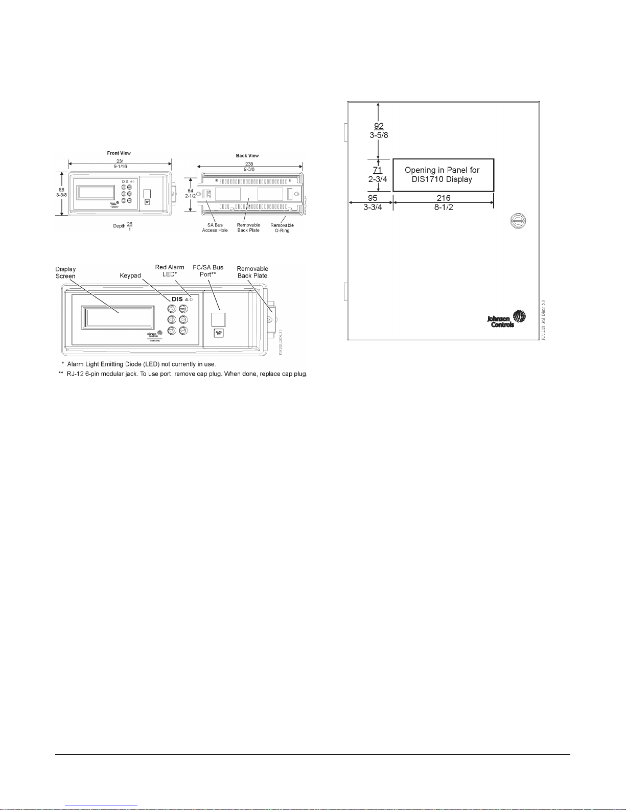
Physical Features
See Figure 2 for the physical features of the display.
Figure 1: DIS1710 Mounting Dimensions, mm/in.
Figure 2: DIS1710 Physical Features
Preparing the Panel
The display is mounted onto the front panel door of the
enclosure. The panel door must have a maximum
thickness of 6-7/20 mm (1/4 in.). Also, if the panel you
intend to use lacks a presized cutout, make the cutout
71 mm x 216 mm (2-2/3 in. x 8-1/2 in.). See Figure 3 for
the recommended cutout location.
Figure 3: DIS1710 Panel Cutout Dimensions, mm/in.
Mounting Display to Enclosure Door
Follow these steps to mount the display onto the front of
the enclosure door (Figure 5):
1. Loosen the two thumbscrews on the back plate, but
do not remove them.
2. Detach the back plate from the display by using a
small Phillips-head screwdriver to remove the two
back plate screws. Tilt the back plate forward to
remove it from the retaining tabs.
3. Insert the O-ring into the gland (slotted groove) in the
back of the display (Figure 4).
4. Insert the display into the front access hole on the
panel door. Hold in place.
5. Carefully insert the back plate to the other side of the
access hole (inside of the panel door) and secure it
to the cutout by hand-tightening the two thumbscrews.
You may need to tilt the back plate to slide it onto the
two bottom retaining tabs.
2DIS1710 Local Controller Display Installation Instructions
Page 3

Figure 4: Attaching the Display into Panel
Cutout
Wiring
The display receives power over the Sensor-Actuator
(SA) Bus from the NCE, FEC, or FAC controller.
Note: Do not connect the display to an NCE, FEC, or
FAC that has an integral display. Also, do not
connect more than one display on the same SA
Bus.
Connecting Cable to Controller
Connect the communication cable (included in box)
between the SA Bus connector on the back of the display
and the SA Bus jack on the front of the controller (Figure
6). The coiled cable is 91 cm (3 ft) in length and can be
stretched to a maximum length of 152 cm (5 ft).
Figure 6: Connecting the SA Bus Cable
6. Using the screwdriver, tighten the two back plate
screws to secure the back plate in place. Tighten the
thumbscrews against the panel to provide a snug fit.
Important: Do not overtighten the thumbscrews.
Overtightening the screws may exert too
much pressure on the back plate.
Figure 5: DIS1710 Back Plate
If the SA Bus jack on the controller is in use, you can wire
the display’s communication cable to the SA Bus terminal
block. Splice one end of the communication cable and
connect it to the SA Bus terminal block using the wiring
designations in Figure 7.
3DIS1710 Local Controller Display Installation Instructions
Page 4

Figure 7: Wiring Cable to SA Bus Terminal Block
Setup and Adjustments
Power On the Controller
1. Supply power to the controller.
2. Close the panel door of the enclosure.
3. Verify that the display is on and initiating the startup
sequence.
Commissioning
The DIS1710 Local Controller Display does not require
commissioning. Cable connection between the DIS1710
Local Controller Display and a commissioned field
controller allows for immediate display function. Ensure
that the communication cable is connected between the
display and the controller. For more information on
commissioning, refer to the Controller Tool Help
(LIT-12011147).
Troubleshooting
Refer to the DIS1710 Local Controller Display Technical
Bulletin (LIT-12011270) for information on how to use
and troubleshoot the DIS1710 display.
Technical Specifications
Table 2: DIS1710 Local Controller Display
MS-DIS1710-0 Local Controller Display for Field Equipment ControllersProduct Code Number
Nominal 15 volts provided by controller over SA Bus.Power Requirement
2 VA maximumPower Consumption
0–50°C (32–122°F)Ambient Operating
Temperature
10–90% RH, 30°C (86°F) maximum dew pointAmbient Operating
Conditions
-40–70°C (-40–158°F)Ambient Storage
Temperature
5–95% RH, 30°C (86°F) maximum dew pointAmbient Storage
Conditions
RJ-12 6-pin jack at Service Port (covered by removable cap-plug) SA Bus connection on back of unitTerminations
Renesas® H8S-2398 16-bit microprocessorProcessor
256 KB Flash Memory 8 KB Random Access Memory (RAM)Memory
RTOS-H8SOperating System
Communication to controller over SA BusNetwork and Serial
Interfaces
4DIS1710 Local Controller Display Installation Instructions
Page 5

Table 2: DIS1710 Local Controller Display
240 x 64 pixels with white LED backlighting (adjustable)Graphic Display
Resolution
85.9 x 238 x 25.8 mm (3.4 x 9.37 x 1.0 in.)Dimensions (Height x
Width x Depth)
Housing
Plastic housing material: ABS + polycarbonate
Protection: IP20 (IEC60529)
Mount to the outside of the enclosure 70.5 x 216.5 mm (2.78 x 8.525 in.)Mounting (Height x
Width)
0.14 kg (0.3 lb)Shipping Weight
Compliance
United States: UL Listed, File E107041, CCN PAZX, UL 916, Energy Management Equipment; FCC
Compliant to CFR47, Part 15, Subpart B, Class A
Canada: UL Listed, File E107041, CCN PAZX7, CAN/CSA C22.2 No. 205, Signal Equipment; Industry
Canada Compliant, ICES-003
Europe: CE Mark – Johnson Controls, Inc. declares that this product is in compliance with the essential
requirements and other relevant provisions of the EMC Directive.
Australia and New Zealand: RCM Mark, Australia/NZ Emissions Compliant
The performance specifications are nominal and conform to acceptable industry standard. For application at conditions
beyond these specifications, consult the local Johnson Controls office. Johnson Controls, Inc. shall not be liable for
damages resulting from misapplication or misuse of its products.
APAC Single Point of Contact:NA/SA Single Point of Contact:European Single Point of Contact:
JOHNSON CONTROLS
WESTENDHOF 3
45143 ESSEN
GERMANY
JOHNSON CONTROLS
507 E MICHIGAN ST
MILWAUKEE WI 53202
USA
JOHNSON CONTROLS
C/O CONTROLS PRODUCT MANAGEMENT
NO. 22 BLOCK D NEW DISTRICT
WUXI JIANGSU PROVINCE 214142
CHINA
507 E. Michigan Street, Milwaukee, WI 53202
Building Efficiency
Johnson Controls® is a registered trademark of Johnson Controls, Inc.
All other marks herein are the marks of their respective owners.© 2016 Johnson Controls, Inc.
www.johnsoncontrols.comPublished in U.S.A.
5DIS1710 Local Controller Display Installation Instructions
 Loading...