

Johnson Controls DCPM12NWM41Q1, DCPM09NWM42Q1, DCPM09NWM41Q1, DCPM12NWM42Q1, DCPM18NWM42Q1 Installation Manual
...Page 1

PREMIUM DUCTLESS SINGLE-SPLIT
INSTALLATION MANUAL
AIR CONDITIONERS AND HEAT PUMPS
MODELS: 22 SEER
3/4 to 3 TONS – 1 PHASE
LIST OF SECTIONS
GENERAL . . . . . . . . . . . . . . . . . . . . . . . . . . . . . . . . . . . . . . . . . . . . . . . . . . . . . .2
SAFETY . . . . . . . . . . . . . . . . . . . . . . . . . . . . . . . . . . . . . . . . . . . . . . . . . . . . . . . .2
SHIPPING AND PACKAGING LIST . . . . . . . . . . . . . . . . . . . . . . . . . . . . . . . . . .2
REQUIRED INSTALLATION TOOLS (NOT SUPPLIED) . . . . . . . . . . . . . . . . . .3
SELECTING THE INSTALLATION LOCATION . . . . . . . . . . . . . . . . . . . . . . . . .3
SPECIFICATIONS . . . . . . . . . . . . . . . . . . . . . . . . . . . . . . . . . . . . . . . . . . . . . . . .5
REFRIGERANT LINE SET REQUIREMENTS . . . . . . . . . . . . . . . . . . . . . . . . . . .6
UNIT DIMENSIONS . . . . . . . . . . . . . . . . . . . . . . . . . . . . . . . . . . . . . . . . . . . . . . .8
TORQUE REQUIREMENTS FOR CAPS AND FASTNERS . . . . . . . . . . . . . . . .9
INDOOR UNIT INSTALLATION . . . . . . . . . . . . . . . . . . . . . . . . . . . . . . . . . . . . . .9
INDOOR UNIT WIRING CONNECTIONS . . . . . . . . . . . . . . . . . . . . . . . . . . . . . .9
PIPE FORMING AND DRAIN PIPING . . . . . . . . . . . . . . . . . . . . . . . . . . . . . . . .10
LIST OF FIGURES
Indoor Clearances . . . . . . . . . . . . . . . . . . . . . . . . . . . . . . . . . . . . . . . . . . . . . . . .3
Prevailing Wind Barrier . . . . . . . . . . . . . . . . . . . . . . . . . . . . . . . . . . . . . . . . . . . . .4
Clearances for Outdoor Unit . . . . . . . . . . . . . . . . . . . . . . . . . . . . . . . . . . . . . . . . .4
Condensate Drainage . . . . . . . . . . . . . . . . . . . . . . . . . . . . . . . . . . . . . . . . . . . . . .5
Typical System Components . . . . . . . . . . . . . . . . . . . . . . . . . . . . . . . . . . . . . . . .7
Indoor Unit Mounting Brackets with Weights & Dimensions . . . . . . . . . . . . . . . . .8
Outdoor Unit Weights & Dimensions . . . . . . . . . . . . . . . . . . . . . . . . . . . . . . . . . .8
Mounting Bracket Spots . . . . . . . . . . . . . . . . . . . . . . . . . . . . . . . . . . . . . . . . . . . .9
Masonry Applications . . . . . . . . . . . . . . . . . . . . . . . . . . . . . . . . . . . . . . . . . . . . . .9
PVC Wall Sleeve Installation . . . . . . . . . . . . . . . . . . . . . . . . . . . . . . . . . . . . . . . .9
Indoor Unit Wall Mounting Bracket . . . . . . . . . . . . . . . . . . . . . . . . . . . . . . . . . . .10
Indoor Electrical Wiring Connections . . . . . . . . . . . . . . . . . . . . . . . . . . . . . . . . .10
Drain Piping Outlets Option . . . . . . . . . . . . . . . . . . . . . . . . . . . . . . . . . . . . . . . .10
Proper and Improper Drain Piping . . . . . . . . . . . . . . . . . . . . . . . . . . . . . . . . . . .11
Left or Right Side Exits . . . . . . . . . . . . . . . . . . . . . . . . . . . . . . . . . . . . . . . . . . . .11
Right or Right Rear Piping . . . . . . . . . . . . . . . . . . . . . . . . . . . . . . . . . . . . . . . . .11
Left or Left Rear Piping . . . . . . . . . . . . . . . . . . . . . . . . . . . . . . . . . . . . . . . . . . . .11
Drain Hose Extension . . . . . . . . . . . . . . . . . . . . . . . . . . . . . . . . . . . . . . . . . . . . .12
Drain Hose Insulation . . . . . . . . . . . . . . . . . . . . . . . . . . . . . . . . . . . . . . . . . . . . .12
Pipe Cutting Approved Method . . . . . . . . . . . . . . . . . . . . . . . . . . . . . . . . . . . . . .12
Deburring Line Set . . . . . . . . . . . . . . . . . . . . . . . . . . . . . . . . . . . . . . . . . . . . . . .12
Flaring Tools . . . . . . . . . . . . . . . . . . . . . . . . . . . . . . . . . . . . . . . . . . . . . . . . . . . .12
Proper and Improper Flaring . . . . . . . . . . . . . . . . . . . . . . . . . . . . . . . . . . . . . . . .12
Connections at Indoor Unit . . . . . . . . . . . . . . . . . . . . . . . . . . . . . . . . . . . . . . . . .13
Flare Nuts Tighting . . . . . . . . . . . . . . . . . . . . . . . . . . . . . . . . . . . . . . . . . . . . . . .13
Indoor Unit Attachment to Mounting Bracket . . . . . . . . . . . . . . . . . . . . . . . . . . .13
Proper and Improper Drain Hose Installation Application . . . . . . . . . . . . . . . . . .13
Indoor Unit Removal . . . . . . . . . . . . . . . . . . . . . . . . . . . . . . . . . . . . . . . . . . . . . .13
Outdoor Unit Installation . . . . . . . . . . . . . . . . . . . . . . . . . . . . . . . . . . . . . . . . . . .14
Outdoor Unit Slab or Frame Installation . . . . . . . . . . . . . . . . . . . . . . . . . . . . . . .14
Outdoor Unit Electrical Connections . . . . . . . . . . . . . . . . . . . . . . . . . . . . . . . . . .14
Outdoor Unit Wiring Terminal Designations . . . . . . . . . . . . . . . . . . . . . . . . . . . .15
Indoor/Outdoor Piping Connections . . . . . . . . . . . . . . . . . . . . . . . . . . . . . . . . . .15
FLARING WORK AND PIPING CONNECTIONS . . . . . . . . . . . . . . . . . . . . . . . 12
INDOOR UNIT INSTALLATION . . . . . . . . . . . . . . . . . . . . . . . . . . . . . . . . . . . . 13
OUTDOOR UNIT INSTALLATION . . . . . . . . . . . . . . . . . . . . . . . . . . . . . . . . . . 13
OUTDOOR UNIT WIRING CONNECTIONS . . . . . . . . . . . . . . . . . . . . . . . . . . . 14
PURGING PROCEDURE, LEAK TEST AND TEST RUN . . . . . . . . . . . . . . . . 16
TEST OPERATION . . . . . . . . . . . . . . . . . . . . . . . . . . . . . . . . . . . . . . . . . . . . . . 18
EMERGENCY OPERATION . . . . . . . . . . . . . . . . . . . . . . . . . . . . . . . . . . . . . . . 18
MAINTENANCE . . . . . . . . . . . . . . . . . . . . . . . . . . . . . . . . . . . . . . . . . . . . . . . . 18
INSTALLATION AND MAINTENANCE OF
HEALTHY FILTER (ACCESSORY) . . . . . . . . . . . . . . . . . . . . . . . . . . . . . . . . . 18
TYPICAL UNIT WIRING DIAGRAM . . . . . . . . . . . . . . . . . . . . . . . . . . . . . . . . . 19
INDOOR AND OUTDOOR UNITS ERROR CODES . . . . . . . . . . . . . . . . . . . . . 31
Outdoor Line Set Connections . . . . . . . . . . . . . . . . . . . . . . . . . . . . . . . . . . . . . . 15
Line Set Connection Insulation and Taping . . . . . . . . . . . . . . . . . . . . . . . . . . . . 16
Utility Bundle . . . . . . . . . . . . . . . . . . . . . . . . . . . . . . . . . . . . . . . . . . . . . . . . . . . 16
Exterior Wall Utility Cover (Optional) . . . . . . . . . . . . . . . . . . . . . . . . . . . . . . . . . 16
Service Valve Operation . . . . . . . . . . . . . . . . . . . . . . . . . . . . . . . . . . . . . . . . . . 17
Gauge Set Connections for Test Leaks, Evacuation Charging . . . . . . . . . . . . . 17
Leak Test Line Set Connection . . . . . . . . . . . . . . . . . . . . . . . . . . . . . . . . . . . . . 18
Emergency Operation . . . . . . . . . . . . . . . . . . . . . . . . . . . . . . . . . . . . . . . . . . . . 18
Filter Replacement . . . . . . . . . . . . . . . . . . . . . . . . . . . . . . . . . . . . . . . . . . . . . . . 19
09K & 12K 115V Outdoor Air Conditioners . . . . . . . . . . . . . . . . . . . . . . . . . . . . 19
09K & 12K Outdoor Air Conditioners . . . . . . . . . . . . . . . . . . . . . . . . . . . . . . . . . 20
18K & 24K 115V Indoor Air Conditioners . . . . . . . . . . . . . . . . . . . . . . . . . . . . . 20
18K & 24K Indoor Air Conditioners . . . . . . . . . . . . . . . . . . . . . . . . . . . . . . . . . . 21
18K Outdoor Air Conditioners . . . . . . . . . . . . . . . . . . . . . . . . . . . . . . . . . . . . . . 21
18K Indoor Air Conditioners . . . . . . . . . . . . . . . . . . . . . . . . . . . . . . . . . . . . . . . . 22
24K Outdoor Air Conditioners . . . . . . . . . . . . . . . . . . . . . . . . . . . . . . . . . . . . . . 22
24K Indoor Air Conditioners . . . . . . . . . . . . . . . . . . . . . . . . . . . . . . . . . . . . . . . . 23
36K Outdoor Air Conditioners . . . . . . . . . . . . . . . . . . . . . . . . . . . . . . . . . . . . . . 23
36K Indoor Air Conditioners . . . . . . . . . . . . . . . . . . . . . . . . . . . . . . . . . . . . . . . . 24
09K & 12K 115V Outdoor Heat Pumps . . . . . . . . . . . . . . . . . . . . . . . . . . . . . . . 24
09K & 12K Outdoor Heat Pumps . . . . . . . . . . . . . . . . . . . . . . . . . . . . . . . . . . . . 25
18K & 24K 115V Heat Pumps . . . . . . . . . . . . . . . . . . . . . . . . . . . . . . . . . . . . . . 25
18K & 24K Indoor Heat Pumps . . . . . . . . . . . . . . . . . . . . . . . . . . . . . . . . . . . . . 26
18K Outdoor Heat Pumps . . . . . . . . . . . . . . . . . . . . . . . . . . . . . . . . . . . . . . . . . 26
18K Indoor Heat Pumps . . . . . . . . . . . . . . . . . . . . . . . . . . . . . . . . . . . . . . . . . . 27
24K Outdoor Heat Pumps . . . . . . . . . . . . . . . . . . . . . . . . . . . . . . . . . . . . . . . . . 27
24K Indoor Heat Pumps . . . . . . . . . . . . . . . . . . . . . . . . . . . . . . . . . . . . . . . . . . 28
30K Outdoor Heat Pumps . . . . . . . . . . . . . . . . . . . . . . . . . . . . . . . . . . . . . . . . . 28
30K Indoor Heat Pumps . . . . . . . . . . . . . . . . . . . . . . . . . . . . . . . . . . . . . . . . . . 29
36K Outdoor Heat Pumps . . . . . . . . . . . . . . . . . . . . . . . . . . . . . . . . . . . . . . . . . 29
36K Indoor Heat Pumps . . . . . . . . . . . . . . . . . . . . . . . . . . . . . . . . . . . . . . . . . . 30
Indoor Unit Front Panel Indicators . . . . . . . . . . . . . . . . . . . . . . . . . . . . . . . . . . . 31
Control Board . . . . . . . . . . . . . . . . . . . . . . . . . . . . . . . . . . . . . . . . . . . . . . . . . . . 31
LIST OF TABLES
Indoor Parts . . . . . . . . . . . . . . . . . . . . . . . . . . . . . . . . . . . . . . . . . . . . . . . . . . . . .3
Outdoor Parts . . . . . . . . . . . . . . . . . . . . . . . . . . . . . . . . . . . . . . . . . . . . . . . . . . . .3
Air Conditioner Electrical Specifications . . . . . . . . . . . . . . . . . . . . . . . . . . . . . . . .5
Heat Pump Electrical Specifications . . . . . . . . . . . . . . . . . . . . . . . . . . . . . . . . . . .6
Insulation Thickness & Material Information . . . . . . . . . . . . . . . . . . . . . . . . . . . . .6
Refrigerant Line Set Requirements . . . . . . . . . . . . . . . . . . . . . . . . . . . . . . . . . . .7
Indoor Unit Dimensions . . . . . . . . . . . . . . . . . . . . . . . . . . . . . . . . . . . . . . . . . . . .8
Outdoor Unit Dimensions . . . . . . . . . . . . . . . . . . . . . . . . . . . . . . . . . . . . . . . . . . . 8
Caps and Fasteners Torque Requirements . . . . . . . . . . . . . . . . . . . . . . . . . . . . . 9
Wire Color Reference . . . . . . . . . . . . . . . . . . . . . . . . . . . . . . . . . . . . . . . . . . . . 10
Flare Nut Torque Recommendations . . . . . . . . . . . . . . . . . . . . . . . . . . . . . . . . . 13
Error Codes - 09K 12K . . . . . . . . . . . . . . . . . . . . . . . . . . . . . . . . . . . . . . . . . . . 32
Error Codes - 18K 24K . . . . . . . . . . . . . . . . . . . . . . . . . . . . . . . . . . . . . . . . . . . 37
Error Codes - 30K 36K . . . . . . . . . . . . . . . . . . . . . . . . . . . . . . . . . . . . . . . . . . . 41
RETAIN THESE INSTRUCTIONS FOR FUTURE REFERENCE
Johnson Controls Unitary Products 898841-UIM-B-0113
Page 2

898841-UIM-B-0113
SECTION I: GENERAL
These instructions are intended as a general guide and do not supersede local codes in any way. Consult authorities having jurisdiction
before installation.
These units must be installed as a matched system as specified in
the UPG Ductless Technical Guide.
SECTION II: SAFETY
This is a safety alert symbol. When you see this symbol on
labels or in manuals, be alert to the potential for personal
injury.
Understand and pay particular attention to the signal words DANGER,
WARNING, or CAUTION.
DANGER indicates an imminently hazardous situation, which, if not
avoided, will result in death or serious injury
• The unit should be installed by an authorized dealer or contractor according to local codes and in compliance with this manual.
• Follow the instructions detailed in the installation manual.
• Confirm proper insulating, taping and bundling of refrigeration lines, main power lines and drain line (see procedure starting on Page 14).
• Perform electrical work according to the installation manual and local codes. Be sure to use a dedicated circuit (do not connect other electr ical
appliances to the same circuit).
• Ground the unit correctly - do not connect the ground wire to a gas pipe, lightning rod, telephone ground or water pipe. Defective grounding
could cause equipment malfunction and/or electric shock.
• Do not damage the wires.
• Shut off the main power when setting up the indoor P.C. board or wiring.
• Use the specified wires to securely connect the indoor and outdoor units. Attach the wires firmly and avoid applying to much pressure to the terminal block - Stranded wire is highly recommended to connect the outdoor unit to the indoor unit. The stranded wire ensures proper system
communication and operation.
• Do not install the unit in a place where flammable gas may leak.
• Do not use intermediate connection of the power cord or a power extension cord.
• The refrigerant temperature tends to get very high. Make sure you keep the electrical wires away from the copper tube.
• Use the parts provided or specified parts for the installation work.
• Securely attach the electrical cover to the indoor unit and the service panel to the outdoor unit.
• When installing or relocating the unit, make sure that no substance other than the specified refrigerant (R410A) enters the refrigerant circuit.
• Do not discharge the refrigerant into the atmosphere. Check that the refrigerant gas does not leak after installation has been completed. If refrigerant leaks during installation, ventilate the room.
• Use appropriate tools and piping materials for installation - the pressure of R410A is 1.6 times higher than R22. Not using the appropriate tools
and materials, or improper installation could cause the pipes to burst causing an injury.
• When pumping down the refrigerant, stop the compressor before disconnecting the refrigerant pipes.
• When installing the unit, securely connect the refrigerant pipes before starting the compressor.
• Fasten a flare nut with a torque wrench as specified in this manual.
• Perform the drainage/piping work securely according to the installation manual - If there is defect in the drainage/piping work, water could drip
from the unit, and damage household items.
• Do not install the outdoor unit where small animals may live. Keep the area around the unit clean
• The included remote control could be shipped in various locations in the unit packaging. Locate remote control before discarding packaging (i.e.
bag assembly, styrofoam, etc.). Unit cannot be properly operated without the included remote control.
.
WARNING indicates a potentially hazardous situation, which, if not
avoided, could result in death or serious injury
CAUTION indicates a potentially hazardous situation, which, if not
avoided may result in minor or moderate injury
alert against unsafe practices and hazards involving only property damage.
Improper or incomplete installation, adjustment, alteration, service or
maintenance could cause personal injury, loss of life, or damage to
property. Installation and service must be performed by a licensed
professional dealer or contractor.
The Clean Air Act of 1990 bans the intentional venting of refrigerant
(CFCs, HCFCs and HFCs) as of July 1, 1992. Approved methods of
recovery, recycling or reclaiming must be followed. Fines and/or
incarceration may be levied for noncompliance.
.
. It is also used to
SECTION III: SHIPPING AND PACKAGING
LIST
Check the unit components for shipping damage. If you see any damage, contact the carrier immediately.
2 Johnson Controls Unitary Products
ASSEMBLED INDOOR UNIT
The assembled indoor unit will include the following items:
Page 3

898841-UIM-B-0113
A
D
C
B
TABLE 1:
Wall mounting bracket
attached to indoor unit)
Indoor Parts
Remote Control 1
Batteries (AAA) 2
screws
Foam tube insulation
(for condensate line
09, 12 & 18 kBtu (5)
24K kBtu (10)
1
ASSEMBLED OUTDOOR UNIT
The assembled outdoor unit will include the following items which are
located with the unit:
TABLE 2:
Auxiliary drain hole plugs
Outdoor Parts
(heat pump only)
Drain plug
(heat pump only)
1 - 3
1
Flare nut 1/4" for small
line on all size units
except 30K which
uses 5/8".
Cable routing guide
with mounting
hardware (18 - 24 kBtu
systems only)
Installation Manual 1
User’s Information
Manual
2. Select a location where the condensate can be easily drained out.
3. Install in a location where there is enough space to access the unit
for routine maintenance (air filter can be removed for cleaning or
replacement).
4. Install where airflow is not blocked.
5. Install in a location for optimized cold or warm air distribution.
6. Install in a location that's not exposed to direct sunlight.
7. Install in a location that's at least 3 ft away from a TV and radio to
avoid possible interferences with the operation of the air conditioner/heat pump.
8. Install in a location that's at least 3 feet away from fluorescent and
incandescent lights to avoid interference with the remote control.
1
1
1
SECTION IV: REQUIRED INSTALLATION
TOOLS (NOT SUPPLIED)
1. Gauge manifold
2. Electronic balance for refrigerant charging
3. Phillips head screwdriver
4. Knife or wire stripper
5. Carpenters level
6. Hammer
7. Drill
8. Tube cutter
9. Tube flaring tool
10. Torque wrench
11. Adjustable wrench
12. Reamer (for de-burring)
13. Vacuum pump (For R410A)
14. Gas leakage detector
SECTION V: SELECTING THE
INSTALLATION LOCATION
INDOOR UNIT (SEE FIGURE 2 FOR INSTALLATION
DIMENSIONS)
1. Install the unit securely in a place that can bear the weight and
vibration of the unit.
Reference Location
A Clearance between unit and ceiling 6 inches
B Clearance between unit and floor 6 feet
C / D Clearance to the right and left of the unit 6 inches
FIGURE 1: Indoor Clearances
Required
Clearance
REMOTE CONTROL
1. Keep the remote control where it is convenient to operate and easily visible.
2. Keep the remote control away from children.
3. When using the I FEEL feature, select a location for the remote
control that's about 4 ft. above the floor.
Johnson Controls Unitary Products 3
Page 4

898841-UIM-B-0113
NOTICE
PREVAILING WINTER WINDS
WIND BARRIER
INLET AIR
12” (305MM) MINIMUM DISTANCE
DISCHARGE AIR
INSTALL UNIT AWAY
FROM WINDOW
E
F
G
H
I
NOTICE
NOTICE
In rooms where inverter type fluorescent lamps are used, the signal
from the wireless remote controller may not be received.
OUTDOOR UNIT (SEE FIGURE 3 FOR
INSTALLATION DIMENSIONS)
1. Some localities are adopting sound ordinances based on the unit's
sound level registered from the adjacent property, not from the
property where the unit is installed. Install the unit as far as possible
from the property line.
2. When possible, do not install the unit directly outside a window.
Glass has a very high level of sound transmission. For proper
placement of unit in relation to a window see Figure 3.
3. Install unit level or, if on a slope, maintain slope tolerance of 2
degrees (or 2 inches per 5 feet) away from building structure.
4. Install the unit high enough above the ground or roof to allow adequate drainage of defrost water and prevent ice or snow build-up
(required for heat pumps).
5. In heavy snow areas, do not locate the unit where drifting will occur.
The unit base should be elevated above the depth of average
snows.
6. When installed in areas where low ambient temperatures exist,
locate unit so winter prevailing winds do not blow directly onto outdoor unit.
7. If unit coil cannot be installed away from prevailing winter winds, a
wind barrier should be constructed. Size barrier at least the same
height and width as outdoor unit. Install barrier 12 inches minimum
from the sides of the unit in the direction of prevailing winds as illustrated in Figure 2.
Reference Location
E Clearance above unit 2 feet
F Clearance between air inlet and structure 12 inches
G
H 7 feet
I 12 inches
FIGURE 3: Clearances for Outdoor Unit
Clearance between unit and structure
Required
Clearance
12 inches
FIGURE 2: Prevailing Wind Barrier
8. Locate unit away from overhanging roof lines which would allow
water or ice to drop on, or in front of, coil or into unit.
9. Install in a location that has good airflow.
10. Install in a location that has a rigid wall or support to minimize the
sound operation and/or vibration.
11. Slab or roof mounting - install the unit a minimum of 4 inches above
the roof or ground surface to avoid ice build-up around the unit.
Locate the unit above a load bearing wall or area of the roof that
can adequately support the unit. Consult local codes for rooftop
applications.
12. Install in a location that's far away from combustible materials and
vapors.
13. Install in a location that's at least 10 ft away from a TV and radio
antennas to avoid possible interferences with the operation of the
air conditioner/heat pump.
14. Install the unit horizontally.
It is advisable to make a piping loop near outdoor unit so as to
reduce vibration.
For increased efficiency, install the outdoor unit in a location where
continuous direct sunlight or excessive water can be avoided as
much as possible.
When operating the air conditioner in low outside temperature, be
sure to follow the instructions described below.
• Never install the outdoor unit in a place where its air inlet/outlet
side may be exposed directly to wind.
• T o prevent exposure to wind, inst all the out door unit with it s air inlet
side facing the wall and a baffle board on the air outlet side.
Avoid the following places for installation where air conditioner trouble
is liable to occur.
• Where flammable gas could leak.
• Where there is an excessive amount of machine oil in the air.
• Where sulfide gas is generated such as a hot spring.
• Where there is high-frequency equipment.
CONDENSATE DRAINAGE REQUIREMENT (HEAT
PUMP ONLY)
Condensate formed during the heating and defrost processes must be
drained from heat pump units. Drain holes are provided in the base of
the units to ensure proper drainage. Heat pumps must be raised when
installed on a concrete pad or the ground to allow drainage to occur. If
the heat pump unit is installed on a wall mounting bracket, insert the
provided drain connector into one of the 1 inch drain holes and attached
a field-provided insulated drain hose to the connector. Use the provided
rubber plugs to cover any unused drain holes. See Figure 4.
4 Johnson Controls Unitary Products
Page 5

FIGURE 4: Condensate Drainage
DRAIN-WATER HOLE
BOTTOM FRAME
DRAIN PLUG
DRAIN CONNECTOR
HOSE (available commerially, inner dia. 0.63”)
NOTICE
SECTION VI: SPECIFICATIONS
POWER SUPPLY AND INDOOR/OUTDOOR WIRE
CONNECTION
• The system should be powered from a dedicated circuit.
• Wiring work should be based on applicable technical standards.
• Wiring connections should be made following the provided
diagrams.
• Make sure all electrical connections are securely tightened.
898841-UIM-B-0113
Solid conductor AWG14 or stranded conductor AWG14 are the MINIMUM allowable wire sizes. There are some applications that will require
larger gauge conductors depending on the voltage and amperage ratings on the data plate and the distance that the conductors will be
routed. It is the installing contractor's responsibility to properly size the
electrical conductors for the equipment and for the application.
All of the indoor units and outdoor units should have the electrical conductors sized using the National Electrical Code (NEC) and the local
authority having jurisdiction whichever is more stringent. If the equipment is installed outside of the United States, all local codes within the
country of origin must be followed.
The Ductless indoor units
volt double insulated copper conductors. The conductors for the indoor
unit can be either solid or stranded copper. When possible the indoor
unit should have stranded wire for the communication to ensure proper
communication between the indoor and outdoor unit(s).
The Ductless outdoor units
volt double insulated copper conductors with the exception of the following models: DHPM30CSM42Q1, DHPM36CSM42Q1, and
DCPM36CSM42Q1, which require 10 gauge wire. The conductors for
the outdoor unit should be solid or stranded copper conductors.
The listed wire sizes are only minimum requirements, as previously
stated, the conductors for both indoor and outdoor units must be
sized using the NEC and local authority having jurisdiction.
must have a minimum of 14 gauge, 600
must have a minimum of 12 gauge, 600
TABLE 3:
Air Conditioners DCPM09NWM42Q1 DCPM09NWM41Q1 DCPM12NWM42Q1 DCPM12NWM41Q1
Power Supply (V, Phase, Hz) 208/230V/1 115V/1 208/230V/1 115V/1
Min. Circuit Ampacity 10 16 10 16
Fan Motor (F.L.A) 0.2 0.38 0.2 0.38
Air Conditioners DCPM18NWM42Q1 DCPM24NWM42Q1 DCPM36NWM42Q1
Power Supply (V, Phase, Hz) 208/230V/1/60HZ 208/230V/1/60HZ 208/230V/1/60HZ
Min. Circuit Ampacity 16 16 17
Fan Motor (F.L.A) 0.28 0.24 0.4
Air Conditioners DCPM09CSM42Q1 DCPM09CSM41Q1 DCPM12CSM42Q1 DCPM12CSM41Q1
Power Supply (V, Phase, Hz) 208/230V/1 115V/1 208/230V/1 115V/1
Max. Fuse Size (time delay) (A) 15 25 15 25
Min. Circuit Ampacity 10 16 10 16
Fan Motor (F.L.A) 0.14 0.17 0.14 0.17
Compressor
Air Conditioners DCPM18CSM42Q1 DCPM24CSM42Q1 DCPM36CSM42Q1
Power Supply (V, Phase, Hz) 208/230V/1/60HZ 208/230V/1/60HZ 208/230V/1/60HZ
Max. Fuse Size (time delay) (A) 20 20 25
Min. Circuit Ampacity 16 16 17
Fan Motor (F.L.A) 0.32 1.1 0.45
Compressor
Air Conditioner Electrical Specifications
INDOOR UNIT
INDOOR UNIT
OUTDOOR UNIT
R.L.A 6.21 12.23 5.34 12.43
L.R.A 13.8 33 13.8 33
OUTDOOR UNIT
R.L.A 9.35 10.45 12.66
L.R.A///
Johnson Controls Unitary Products 5
Page 6

898841-UIM-B-0113
NOTICE
TABLE 4:
Heat Pumps DHPM09NWM42Q1 DHPM09NWM41Q1 DHPM12NWM42Q1 DHPM12NWM41Q1
Power Supply (V, Phase, Hz) 208/230V/1 115V/1 208/230V/1 115V/1
Min. Circuit Ampacity 10 16 10 16
Fan Motor (F.L.A) 0.2 0.38 0.2 0.38
Heat Pumps DHPM18NWM42Q1 DHPM24NWM42Q1 DHPM30NWM42Q1 DHPM36NWM42Q1
Power Supply (V, Phase, Hz) 208/230V/1/60HZ 208/230V/1/60HZ 208/230V/1/60HZ 208/230V/1/60HZ
Min. Circuit Ampacity 16A 16A 15 23
Fan Motor (F.L.A) 0.28A 0.24A 0.4 0.47
Heat Pumps DHPM09CSM42Q1 DHPM09CSM41Q1 DHPM12CSM42Q1 DHPM12CSM41Q1
Power Supply (V, Phase, Hz) 208/230V/1 115V/1 208/230V/1 115V/1
Max. Fuse Size (time delay) (A)15251525
Min. Circuit Ampacity 10 16 10 16
Fan Motor (F.L.A) 0.14 0.17 0.14 0.17
Compressor
Heat Pumps DHPM18CSM42Q1 DHPM24CSM42Q1 DHPM30CSM42Q1 DHPM36CSM42Q1
Power Supply (V, Phase, Hz) 208/230V/1/60HZ 208/230V/1/60HZ 208/230V/1/60HZ 208/230V/1/60HZ
Max. Fuse Size (time delay) (A) 20A 20A 25 35
Min. Circuit Ampacity 16A 16A 15 23
Fan Motor (F.L.A) 0.32A 1.1A 0.45 0.73
Compressor
Heat Pump Electrical Specifications
INDOOR UNIT
INDOOR UNIT
OUTDOOR UNIT
R.L.A 6.21 12.23 5.34 12.43
L.R.A 13.8 33 13.8 33
OUTDOOR UNIT
R.L.A 9.35A 10.45A 11.42 16.95
L.R.A / / / /
Connecting Wires and the Ground Wire
• Use double insulated copper wire with 600V insulation.
• Use copper conductors only.
• Follow all local electrical codes.
Power Supply Cable and Ground Wire
• Use copper conductors only.
• Follow all local electrical codes.
The the indoor unit is powered from the outdoor unit, depending on
local code, a disconnect switch needs to be installed to a power supply circuit.
SECTION VII: REFRIGERANT LINE SET
• To prevent condensation, insulate the two refrigerant pipes.
• Refrigerant pipe bending radius must be 4 in. (100 mm) or more.
Be sure to use the insulation of specified thickness (refer to Table 5).
Excessive insulation may cause incorrect installation of the indoor
unit, and too little insulation may cause condensate to form.
• The unit has flared connections on both indoor and outdoor sides
• Remove the valve cover from the outdoor unit then connect the
pipe
• Refrigerant pipes are used to connect the indoor and outdoor units
• Be careful not to crush or over bend the pipe in pipe bending
• Refrigerant adjustment
• If pipe length exceeds 25 ft. (7.5 m), additional refrigerant (R410A)
charge is required (The outdoor unit is charged with refrigerant for
pipe length up to 25 ft. [7.5 m]).
REQUIREMENTS
TABLE 5:
Insulation Thickness & Material Information
Pipe
Liquid Line .375 (9.52) 0.0315 (0.8) 0.315 (8)
Gas Line .625 (15.9) 0.0394 (1.0) 0.315 (8)
Outside Diameter
Inch (mm)
Minimum Wall
Thickness
Insulation
Thickness
Insulation
Material
Heat Resistant Foam Plastic
0.045 Specific Gravity
6 Johnson Controls Unitary Products
Page 7

898841-UIM-B-0113
E
G
H
TAPE
L
REFRIGERANT LINE SET, CONDENSATE LINE
AND INDOOR / OUTDOOR CABLE
RETURN AIR
B
C
D
K
SUPPLY AIR
A
D
DISPLAY
INDICATORS
COOL
DRY
FAN
HEAT
RUN
TEMPERATURE SETTING
INDOOR AMBIENT TEMPERATURE
OR ERROR CODE
NOTE:
Temperature can be
displayed in either fahrenheit or celsius.
F
IMPORTANT:
The refrigerant metering device for this
system is located in the outdoor unit.
This makes it necessary to insulate the
refrigerant lines individually to prevent
sweating.
UTILITY
BUNDLE
WIRELESS REMOTE
CONTROL
OUTDOOR UNIT
(AIR CONDITIONER
OR HEAT PUMP)
AIR IN
AIR OUT
OUTDOOR UNIT
TERMINAL BLOCK
TO INDOOR
UNIT
TO POWER
SUPPLY
ACCESS COVER FOR
SERVICE VALVES
(-18, -24 AND -30 ONLY)
2-WAY SHUT-OFF VAVLE
2-WAY SUCTION / VAPOR LINE SERVICE
VALVE (FLARE CONNECTION)
H
J
A. Remote control
B. Front Panel
C. Filters
D. Guide louver with display
E. Line set (wrapped in foam insulation)
F. UV-rated tape (field-provided)
G. Wiring (field-provided)
H. Condensate drain line (field-provided)
(wrapped in foam insulation). Recommend
installation of a vent when making long
horizontal runs on condensate line.
I. 2-way suction / vapor line service valve
and 2-way shut-off valve.
J. Access cover for power and control wiring
connections.
K. Indoor unit wiring connections (under access plate).
L. Communication cable (30 kBtu system only)
INDOOR UNIT
I
TABLE 6:
Refrigerant Line Set Requirements
AC & HP Indoor Units D(C,H)PM09NWM D(C,H)PM12NWM D(C,H)PM18NWM D(C,H)PM24NWM DHPM30NWM D(C,H)PM36NWM
AC & HP Outdoor Units D(C,H)PM09CSM D(C,H)PM12CSM D(C,H)PM18CSM D(C,H)PM24CSM DHPM30CSM D(C,H)PM36CSM
Connection Pipe length ft. 24.6 24.6 24.6 24.6 24.6 24.6
Connection Pipe Gas
Additional Charge
oz/ft. 0.2 0.2 0.2 0.2 0.5 0.5
Outer Diameter Liquid Pipe Inch 1/4 1/4 1/4 1/4 1/4 1/4
Outer Diameter Gas Pipe Inch 3/8 3/8 1/2 1/2 5/8 5/8
Max Distance Height ft. 32.8 32.8 32.8 32.8 32.8 32.8
Max Distance Length ft. 49.2 49.2 82 82 98.4 98.4
Refrigerant Metering Device Type Electronic Expansion Valve
FIGURE 5: Typical System Components
Johnson Controls Unitary Products 7
Page 8

898841-UIM-B-0113
09K 12K
18K
24K
A
C
B
256
27.3 (693)
5.3
(135)
2.1 (53)
7.8 (198)
11.8 (300)
2.2 (56)
2.2 (56)
1.8 (46)
.6 (15)
.6 (15)
3.3 (84)
22.2 (564)
33.3 (846)
6.3
(160)
4.9
(124)
40.1 (1018)
7.4
(188)
2.6 (66)
3.5 (89)
1.4 (36)
22.6 (574)
2.5 (64)
1.8 (46)
2.6 (66)
27 (686)
2.6 (66)
1 (25)
4
(102)
4
(102)
1 (25)
2.6 (66)
21.3 (541)
2.2 (56)
2.2 (56)
2 (51)
4 (101)
5 (127)
2 (51)
30K & 36K
10.9 (277)
B
A
C
SECTION VIII: UNIT DIMENSIONS
FIGURE 6: Indoor Unit Mounting Brackets with Weights & Dimensions
TABLE 7:
Indoor Unit Dimensions
Model Size A B C
09K & 12K 33 (838) 7 (178) 10.9 (277) 31 lbs (14 kg) 37 lbs (17 kg)
18K 37 (940) 8 (203) 12 (305) 31 lbs (14 kg) 46 lbs (21 kg)
24K 39.8 (1011) 8.5 (216) 12.4 (315) 46 lbs (21 kg) 56 lbs (25 kg)
30K & 36KK 53 (1346) 10 (254) 12.9 (328) NA 60 lbs (27 kg)
FIGURE 7: Outdoor Unit Weights & Dimensions
TABLE 8:
Outdoor Unit Dimensions
Model SizeABC
09K 33 (838) 12.6 (320) 21 (533) 91 lbs (41 kg) 110 lbs (50 kg)
12K 33 (838) 12.6 (320) 21 (533) 97 lbs (44 kg) 119 lbs (54 kg)
18K 35 (889) 13.4 (340) 27.5 (699) 121 lbs (55 kg) 148 lbs (67 kg)
24K 38 (965) 16.9 (429) 31.1 (790) 132 lbs (60 kg) 161 lbs (73 kg)
30K & 36K 38 (965) 16.9 (429) 31.1 (790) NA 163 lbs (74 kg)
8 Johnson Controls Unitary Products
Unit Gross Weight
Air Conditioner Heat Pump
Air Conditioner Heat Pump
Unit Gross Weight
Page 9

SECTION IX: TORQUE REQUIREMENTS
NOTICE
Mark on the middle of it
5.9inch
Left
Space
to the
wall
above
Right
Space
to the
wall
above
5.9inch
WALL
WALL
LEVELING DEVICE
(REAR PIPING HOLE)
(REAR PIPING HOLE)
DRILL PILOT HOLES
USE ANCHORS
INSTALLANCHORS
INSIDE
OUTSIDE
CAULKING
2.2”
WALL PIPE
NOTICE
FOR CAPS AND FASTNERS
When servicing or repairing HVAC components, ensure the fasteners
are appropriately tightened. The table below provides torque values for
fasteners.
TABLE 9:
Caps and Fasteners Torque Requirements
Recommended Torque
Parts
English
(ft. - lb.)
Service valve cap 8 ft. - lb. 11
Sheet metal screws 16 ft. - lb. 2
Machine screws #10 27 ft. - lb. 3
Compressor bolts 7 ft. - lb. 10
Gauge port seal cap 8 ft. - lb. 11
Only use Allen wrenches of sufficient hardness (50Rc - Rockwell
Harness Scale minimum). Fully insert the wrench into the valve stem
recess.
Service valve stems are factory-torqued (from 9 ft-lbs for small
valves, to 25 ft-lbs for large valves) to prevent refrigerant loss during
shipping and handling. Using an Allen wrench rated at less than
50Rc risks rounding or breaking off the wrench, or stripping the valve
stem recess.
SECTION X: INDOOR UNIT INSTALLATION
INSTALLING THE WALL MOUNTING BRACKET
Determine that the wall will support the weight of the indoor unit. Refer
to system specifications for indoor unit weight. Install the wall mounting
bracket and make sure it's positioned horizontally and vertically. The
indoor unit must be installed level on the wall to allow proper condensate drainage.
1. Determine the best exit location for utility bundle (line set, condensate line and wiring).
2. Use the wall mounting bracket as a template to determine the exit
point for utility bundle. Use a carpenter's level or tape measure to
verify the wall mounting bracket is horizontally level and mark the
boring points on the wall. See Figure 11.
3. Prior to making the hole and installing wall sleeve for the utility bundle, check to ensure that neither studs nor plumbing are directly
located behind the hole location.
4. Secure the wall mounting bracket to the wall using the provided
screws. If possible, align the rear panel screw holes with wall stud
locations marked on the wall. Make sure you use as many screws
into studs as possible. All other screws must be secured using plastic wall anchors. See Figure 13.
5. If the wall is made of brick, concrete or other similar material, then
drill pilot holes in the wall. Insert field-provided anchors for mounting screws. See Figure 13.
It is important to use all screws provided to secure the wall mounting
bracket to the wall. Additional holes may be drilled through the metal
wall mounting bracket to better secure wall bracket to wall studs.
Johnson Controls Unitary Products 9
(Newton Meter)
898841-UIM-B-0113
Metric
FIGURE 8: Mounting Bracket Spots
FIGURE 9: Masonry Applications
WALL HOLE DRILLING
Be sure to caulk the gaps around the pipes with caulking material to
prevent water leakage.
1. Determine the wall hole position.
2. Drill a 2-1/2 inch diameter hole in the wall. The hole should be
slightly downward slant 3/16" to 3/8" (5 to 10 mm) lower than the
indoor side.
3. Measure the thickness of the wall from inside to outside edges and
cut field-provided PVC pipe at a slight angle 1/4" (6mm) shorter
than the thickness of the wall.
4. Place a field-provided plastic cover on the outside end of the PVC
pipe and insert the pipe in the wall hole.
5. After completing refrigerant piping, wiring, and drain piping, caulk
pipe hole gap with putty.
FIGURE 10: PVC Wall Sleeve Installation
SECTION XI: INDOOR UNIT WIRING
CONNECTIONS
When the indoor unit is powered from the o utdoor unit, a disconnect switch needs to be installed to power supply circuit
between indoor and outdoor units depending on local codes.
Page 10

898841-UIM-B-0113
WALL
WIRING
FIELD PROVIDED
PVC WALL SLEEVE
GROUND
WIRE
TERMINAL BLOCK
TERMINAL COVER
SCREW
SCREW
CORD CLAMP
CONNECTING CABLE
TERMINAL BLOCK
YELLOW-GREEN
BLUE
BROWN
BLACK
CONNECTING
CABLE
ABOUT 5.9”
2.8”
0.39”
GROUND
LINE
0.39”
1.97”
RIGHT
REAR RIGHT
RIGHT DOWNWARD REAR LEFT
LEFT DOWWARD
LEFT
Mis-wiring could damage unit or cause communication errors
between indoor and outdoor unit.
1. Remove the front panel.
2. Open the front panel upward and pull it toward you.
3. Remove the terminal cover and cord clamp.
4. Insert the connecting cable (according to local codes) into the pipe
hole on the wall.See Figure 11.
5. Pull the connecting cable through the cable slot on the rear case so
that it protrudes about 6 inches (~15 cm) out of the front.
6. Connect the ground wire to the ground terminal of electrical box.
7. Insert the connecting cable fully into the terminal block and secure it
with screws while making sure no part of its core is visible. Make
sure you don't mis-wire the unit. See Figure 12.
8. Firmly tighten the terminal screws to prevent them from getting
loose.
9. Secure the connecting cable with the cord clamp.
10. Attach the terminal cover and front panel on the indoor unit.
TABLE 10:
Color Code Color
Wire Color Reference
Color Code or
Symbol
Color
WH White BN Brown
YE Yellow BU Blue
RD Red BK Black
YEGN Yellow Green
FIGURE 11: Indoor Unit Wall Mounting Bracket
Be sure to refer to the wiring system diagram labeled inside the front
panel.
Check local electrical regulations for any specific wiring instructions
or limitations.
10 Johnson Controls Unitary Products
FIGURE 12: Indoor Electrical Wiring Connections
SECTION XII: PIPE FORMING AND DRAIN
PIPING
FIGURE 13: Drain Piping Outlets Option
PIPE FORMING
Interchange the drain cap and the drain hose.
1. Place the drain hose below the refrigerant piping.
2. Make sure the drain hose is not bent or kinked.
3. Do not pull the hose when applying the tape.
4. When the drain hose passes the room, be sure to wrap field-provided insulation material around it.
5. In the case of bending refrigerant piping, keep the following precautions in mind to avoid abnormal sounds that may be generated if
improper work is conducted.
a. Do not press the refrigerant pipes onto the bottom frame.
b. Do not press the refrigerant pipes on the front grille.
Page 11

FIGURE 14: Proper and Improper Drain Piping
SLIT
RIGHT
PIPING
BOTTOM
PIPING
BIND WITH VINYL TAPE
PIPE (TOP) REAR PIPING
INDOOR UNIT
DRAIN HOSE (BOTTOM)
INDOOR UNIT
DRAIN HOSE
DRAIN CAP
FOR LEFT OUTLET
PIPING, CUT OFF
THE PIPING OUTLET
CUTTING GROOVE
WITH A HACKSAW
REMOVE DRAIN
CAP BY PULLING
AT THE PROJECTION
AT THE END OF THE
CAP WITH PLIERS, ETC.
How to replace the drain plug and drain hose
• How to remove the drain cap
Clamp drain cap with needle-nose pliers, and pull out.
• How to remove the drain hose
The drain hose is secured in place by a screw.
Remove the screw securing the drain hose, then
pull out the drain hose.
• How to attach the drain cap
1. Insert hexagonal wrench (0.16inch).
2. Firmly insert drain cap.
• How to attach the drain hose
secure it in place using the original screw.
Do not apply lubricating oil
(refrigerant machine oil) when
inserting the drain cap. If applied
deterioration and leakage of the
drain plug may occur.
Insert a hexagon wrench
(4 mm)
No gap
Drain Hose
0.16”
Insulation
fixing screw
RIGHT OR RIGHT REAR PIPING
For Right Side Utility Bundle Exit - Cut out the corner of the right/left
plastic cabinet with a hacksaw or similar tool. See Figure 15.
1. Put the refrigerant piping and the drain hose together. Position
them to the left side and then firmly apply piping tape from the end.
2. Insert the drain hose into field-provided PVC sleeve and hook the
upper part of the indoor unit on the wall mounting bracket.
3. Check if the indoor unit is hooked securely on the wall mounting
bracket by trying to move the unit left and right.
4. Thrust the lower part of the indoor unit into the wall mounting
bracket.
898841-UIM-B-0113
LEFT OR LEFT REAR PIPING
For Left Side Utility Bundle Exit - Cut out the corner of the right/left
plastic cabinet with a hacksaw or similar tool.
Make sure you reattach the drain hose and the drain cap in case of left
or left rear piping. Otherwise, it could cause drops of water to drip from
the drain hose.
1. Put the refrigerant piping and the drain hose together then firmly
apply felt tape from the end.
2. Pull out the drain cap at the rear right of the indoor unit.
3. Pull out the drain hose at the rear left of the indoor unit.
4. Put the drain cap into the section to which the drain hose is to be
attached at the rear of the indoor unit.
5. Insert the drain hose fully into the drain pan at the rear right of the
indoor unit.
6. Insert the drain hose into field-provided PVC sleeve and hook the
upper part of the indoor unit on the wall mounting bracket.
FIGURE 15: Left or Right Side Exits
FIGURE 16: Right or Right Rear Piping
Johnson Controls Unitary Products 11
FIGURE 17: Left or Left Rear Piping
REAR OR DOWNWARD PIPING
1. Put the refrigerant piping and the drain hose together then firmly
apply felt tape from the end. Use bandage stopper at the end of felt
tape.
2. Insert the drain hose into field-provided PVC sleeve and hook the
upper part of the indoor unit on the wall mounting bracket.
Page 12

898841-UIM-B-0113
SHIELD PIPE
DRAIN HOSE
INSIDE THE ROOM
EXTENSION
DRAIN HOSE
DRAIN HOSE
INSULATION (DRAIN HOSE)
COPPER
PIPE
SLANTED
UNEVEN ROUGH
90°
PIPE
REAMER
POINT DOWN
"A"
BAR
HANDLE
YOKE
CONE
RED ARROW MARK
CLAMP HANDLE
COPPER PIPE
BAR
Outside Dia.
Inch
0.24
0.37
0.47
0.63
0.75
A
Inch
0~0.02
~0.02
~0.02
~0.04
~0.05
0
0
0
0.04
SMOOTH ALL ROUND
INSIDE IS SHINY WITHOUT SCRATCHES
= IMPROPER FLARING =
EVEN LENGTH
ALL ROUND
INCLINED
SURFACE
DAMAGED
CRACKED
UNEVEN
THICKNESS
1. In order to align the drain hose and drain cap, be sure to insert
securely and vertically. Incline insertion will cause water leakage.
2. After removing drain hose, be sure not to forget mounting drain
cap.
3. Be sure to fix the drain hose with tape to the bottom of piping.
4. Prevent drain water from freezing in low temperature environment.
When installing indoor unit’s drain hose outdoors, necessary measure for frost protection should be taken to prevent drain water
freezing.
• Under low temperature environment (when outdoor temperature under 32 °F), after cooling operation is executed, water in
the drain hose could be frozen.
• Once drain water is frozen, the drain hose will be blocked and
water leakage may result from indoor unit.
DRAIN PIPING
• If the extension drain hose has to pass through a room, make
sure it's wrapped with commercially sold insulation.
• The drain hose should point downward for easy drain flow.
• If the drain hose provided with the indoor unit is too short, make
sure you connect it with a field-provided drain hose.
• When connecting the drain hose to the hard vinyl chloride pipe,
make sure it's inserted securely into the pipe.
DRAIN HOSE JUNCTION
• If drain hose extension or embedded drain piping is required, use
appropriate parts that match the hose front end. See Figure 18.
• Insert drain hose into the handle of drain pan, and join drain hose
and connecting hose according to Figure 18.
• Attach the Insulation (Drain hose) to the drain hose. See Figure
19.
SECTION XIII: FLARING WORK AND
PIPING CONNECTIONS
FLARING WORK
Main cause for refrigerant leakage is due to defect in the flaring work.
Carry out correct flaring work using the following procedure.
1. Measure the distance between the indoor and outdoor units.
2. Cut the copper pipe about 6 to 8 inches (15 to 20 cm) longer than
the measured distance with a pipe cutter.
FIGURE 20: Pipe Cutting Approved Method
3. Use a pipe reamer or file to completely remove all burrs from the
cut cross section of the pipe.
a. Put the end of the copper pipe in a downward direction to avoid
having burrs drop in the piping.
FIGURE 21: Deburring Line Set
4. Remove flare nuts attached to indoor and outdoor units then put
them on pipes that have completed burrs removal (not possible to
put them on after flaring work).
5. Use a flaring tool to perform flaring work at the end of the copper
pipe. Use the table below as a guideline when performing flaring
work.
FIGURE 18: Drain Hose Extension
FIGURE 19: Drain Hose Insulation
Insert the drain hose and drain cap into the drain port, making sure
that it comes in contact with the back of the drain port, and then
mount it. If the drain hose is not connected properly, leaking will
occur.
12 Johnson Controls Unitary Products
FIGURE 22: Flaring Tools
6. Check your flaring work and if it's found to be defective, cut off the
defective flare section and redo number 5.
FIGURE 23: Proper and Improper Flaring
7. When flaring is complete, align the center of the pipes and sufficiently tighten the flare nut by hand.
Page 13

FIGURE 24: Connections at Indoor Unit
INDOOR UNIT TUBING
FLARE NUT PIPES
WRENCH
INDOOR UNIT TUBING
OPEN-END WRENCH (FIXED)
FLARE NUT
CONNECTION PIPE
A
MOUNTING PLATE
MARKING
DO NOT RISE THE DRAIN HOSE
DO NOT FORM THE DRAIN HOSE
INTO THE WAVED SHAPE
50 mm
OR MORE
DO NOT PUT THE
DRAIN HOSE END
INTO WATER
DO NOT PUT THE DRAIN
HOSE END IN THE
DRAINAGE CONTAINER
PUSH
PUSH
8. Tighten the flare nut using a wrench.
FIGURE 25: Flare Nuts Tighting
898841-UIM-B-0113
5. Carefully bend the bundle (line set, condensate line and cable) to
run along the outside wall toward the outdoor unit. Downward slope
of wall sleeve will ensure proper condensate drainage.
FIGURE 27: Proper and Improper Drain Hose Installation Application
Pull the indoor unit toward you to confirm that it is firmly hooked
on the mounting bracket.
For detaching the indoor unit from the installation plate, pull the indoor
unit toward you while pushing the bottom up at the specified places.
TABLE 11:
Flare Nut Torque Recommendations
Outside
Diameter
Inches mm
Recommended
English
(ft. - lb.)
Torque
Metric
(Newton Meter)
1/4” 6.35 15 ft - lb. 20
3/8” 9.52 26 ft - lb. 35
1/2” 12.70 41 ft - lb. 55
5/8” 15.88 48 ft - lb. 65
SECTION XIV: INDOOR UNIT
INSTALLATION
1. Shape the refrigerant line set so that it can be guided either out the
back of the indoor unit or through either side of the indoor unit
frame, then through the wall sleeve to the outside unit.
2. Pass the drain hose and refrigerant pipes through the wall hole then
set the indoor unit on the mounting bracket hooks by using the
markings at the top of the indoor unit as a guide.
FIGURE 26: Indoor Unit Attachment to Mounting Bracket
3. Try moving the indoor unit to right and left to confirm that it is firmly
hooked on the installation plate.
4. While pressing the indoor unit onto the wall, hook it at the lower part
on the installation plate.
FIGURE 28: Indoor Unit Removal
6. Use the provided foam insulation to wrap the factory installed condensate line.
7. Connect indoor unit factory installed condensate line to field-provided condensate drain pipe.
8. Use tape approved for waterproofing line connections to secure the
field-provided pipe to the factory-installed condensate line.
9. Put water in the drain pan and make sure that the water is being
drained outside.
Install the drain pipe for proper drainage. Improper drainage can
result in water dripping inside the room.
SECTION XV: OUTDOOR UNIT
INSTALLATION
Refer to page 4 instructions when considering unit positioning and page
4 for condensate drainage requirements (heat pump).
SLAB OR ROOF MOUNTING
• Install the unit a minimum of 4 inches (102 mm) above the roof or
ground surface to avoid ice build-up around the unit.
• Locate the unit above a load bearing wall or area of the roof that
can adequately support the unit.
• Consult local codes for rooftop applications.
Johnson Controls Unitary Products 13
Page 14

898841-UIM-B-0113
BUILDING STRUCTURE
GROUND
LEVEL
Install unit level or maintain slope tolerance of 2 degrees
( or 2 inches per 5 feet [50 mm per 1.5 m] away from building structure.
NOTICE
FOUR FIELD PROVIDED ANCHOR BOLTS
NOTICE
ROUTE WIRES
THROUGH
ROUTING
PLATE
ACCESS PLATE
FIGURE 29: Outdoor Unit Installation
This system contains both refrigerant and oil. Some rubber roofing
material may absorb oil. This will cause the rubber to swell when it
comes into contact with oil. The rubber will then bubble and could
cause leaks. Protect the roof surface to avoid exposure to refrigerant
and oil during service and installation. Failure to follow this notice
could result in damage to roof surface.
SECURING OUTDOOR UNIT TO SLAB OR FRAME
If the outdoor unit is installed on a field-provided slab or frame, use lag
bolts or equivalent to secure the outdoor unit to the slab or frame.
Mis-wiring could damage unit or cause communication errors
between indoor and outdoor unit.
• Refer to unit nameplate for minimum circuit ampacity and maximum overcurrent protection size
• Local codes may require a disconnect between the indoor and outdoor units
• The main system circuit breaker and outdoor unit disconnect
switch should be sized per local codes and unit requirements
• Stranded wire must be used to connect the outdoor unit to the
indoor unit. The stranded wire is necessary to ensure proper system communication and operation.
• Make sure you use an approved circuit breaker or switch
Model Fuse or Circuit Breaker Capacity
9K & 12K 20A
18K & 24k 25A
30K & 36k 30A
1. Remove outdoor unit access panel.
2. Route all wiring to outdoor unit through the wire routing plate.
FIGURE 30: Outdoor Unit Slab or Frame Installation
SECTION XVI: OUTDOOR UNIT WIRING
CONNECTIONS
In the United States, wiring must conform with current local codes
and the current National Electric Code (NEC). In Canada, wiring
must conform with current local codes and the current Canadian
Electrical Code (CEC).
The main system circuit breaker or disconnect should be sized per
unit requirements and should be installed adjacent to outdoor unit.
14 Johnson Controls Unitary Products
FIGURE 31: Outdoor Unit Electrical Connections
3. Connect the control wiring and power supply wiring to the outdoor
unit wiring terminals according to the figures shown in this section.
4. The unit must be grounded according to local codes.
5. Fasten the power supply cord and control wiring with cord clamp.
6. Secure wiring using built-in wire strain relief.
7. Install the outdoor unit access panel back.
Page 15

FIGURE 32: Outdoor Unit Wiring Terminal Designations
OUTDOOR UNIT
TERMINALS
N(1)
23
L1 N
(DATA)
(NEUTRAL)
(GND)
N(1)
2
3
(NEUTRAL)
(GND)
(L1)
N(1)
23
L1 L2
(DATA)
(L2)
(GND)
N(1)
2
3
(GND)
(L1)
N(1) 2 3
N(1)
2
3
L1
L2
(L2)
(GND)
(L1)
(GND)
208-230V SYSTEMS
30 & 36 KBTU (208-230V)
SYSTEM ONLY
115V SYSTEMS
INDOOR UNIT TERMINALS
INDOOR UNIT TERMINALS
INDOOR UNIT TERMINALS
OUTDOOR UNIT
TERMINALS
OUTDOOR UNIT
TERMINALS
OUTDOOR UNIT
TERMINALS
(NEUTRAL)
(NEUTRAL)
(DATA)
NOTICE
MALE FLARE
CONNECTION
APPLY REFRIGERANT
LUBRICANT HERE
A
B
OUTDOOR UNIT
LIQUID SIDE PIPING
(SMALLER DIAMETER)
TORQUE WRENCH
GAS SIDE PIPING
(BIGGER DIAMETER)
REFRIGERANT PIPING CONNECTIONS
A Service port cap protects the service port core from contamination
and serves as the primary leak seal. To access service port:.
1. Remove service port cap with an appropriate sized wrench.
2. Connect gauge set to service port.
3. When testing is complete, replace service port cap and tighten as
follows:
a. With torque wrench - Finger tighten then torque cap per Table 11
requirements.
b. Without torque wrench - Finger tighten then use appropriate
sized wrench to turn an additional 1/6 turn clockwise.
Stem cap protects the valve stem from damage and serves as the primary seal. Replace the stem cap and tighten as follow:
1. With torque wrench - Finger tighten and use torque cap per Table
11.
2. Without torque wrench - Finger tighten then use an appropriate
sized wrench to turn an additional 1/12 turn clockwise.
• Fasten flare nut with a torque wrench as specified in Table 9.
• When fastened too tight, flare nut may break after a long period
and cause refrigerant to leak.
898841-UIM-B-0113
FIGURE 33: Indoor/Outdoor Piping Connections
OUTDOOR UNIT CONNECTION
• Apply a sealing cap or water proof tape to prevent dust or water
from getting into the refrigerant piping before it is connected.
• Apply refrigerant lubricant to the matching surfaces of the flared
line set and union before connecting them together. This will
reduce refrigerant leaks.
• Align the flared refrigerant line with valve connection then tighten
the flare nut lightly at first to obtain a smooth match. Use tightening toque Table 11 as a guideline.
INDOOR UNIT CONNECTION
• Connect both liquid and gas pipes to indoor unit.
• Apply a sealing cap or water-proof tape to prevent dust or water
from getting into the refrigerant piping before it is connected.
• Apply a thin coat of refrigerant oil on the seal surface of the pipe.
• For connection, first align the union tube and flared refrigerant
line with each other then tighten the flare nuts lightly at first to
obtain a smooth match.
• Use tightening toque Table 11 as a guideline for indoor unit side
union joint section and tighten using two wrenches. Excessive
tightening may damage the flare section.
Johnson Controls Unitary Products 15
FIGURE 34: Outdoor Line Set Connections
Page 16

898841-UIM-B-0113
PLASTIC BANDS
INSULATION MATERIAL
CONNECTION
PIPE
VINYL TAPE
(WIDE)
INDOOR
UNIT PIPE
WRAP WITH VINYL TAPE
WRAP WITH VINYL TAPE
PIPE
DRAIN HOSE
VINYL TAPE (WIDE)
INDOOR UNIT
CONNECTING
CABLE
AUXILIARY PIPES
INSTALLATION
PLATE
FIELD PROVIDED PROTECTIVE
CHANNEL (UTILITY BUNDLE INSIDE)
INSULATION AND TAPING
1. Cover piping joints with pipe cover.
2. For outdoor unit, insulate every pipe including all pipe joints.
3. Using piping tape, apply taping starting from entry of outdoor unit.
a. S top the end of piping tape with tape that has an adhesive agent
attached.
b. When pipes have to be arranged through above ceiling, closet or
where temperature and humidity are high, make sure you wind
additional commercially sold insulation to prevent sweating.
4. An optional field-provided exterior wall channel may be used in lieu
of taping the utility bundle to protect the bundle from UV rays,
weather, etc. See Figure 37.
FIGURE 35: Line Set Connection Insulation and Taping
FIGURE 37: Exterior Wall Utility Cover (Optional)
SECTION XVII: PURGING PROCEDURE,
LEAK TEST AND TEST RUN
FIGURE 36: Utility Bundle
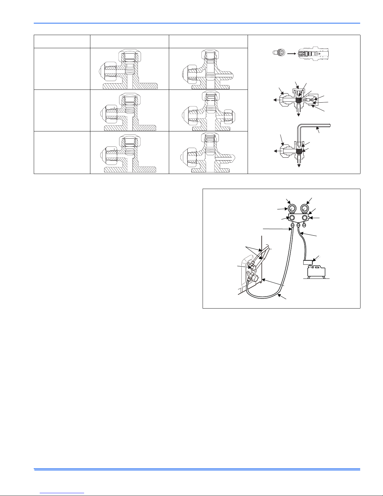
SERVICE VALVES
The outdoor unit suction/vapor 2-way service valve is used to purge air,
test for leaks, check operating pressures and add refrigerant to system.
This valve is equipped with a service port which has a factory installed
valve core. Figure below provides information on how to access and
operate the 2-way angle-type service valve and 2-way shut-off valve.
After the piping has been connected to the indoor unit, perform the air
purge.
16 Johnson Controls Unitary Products
Page 17
898841-UIM-B-0113
SUCTION/VAPOR
2-WAY SERVICE VALVE
HOSE WITH
SCHRADER VALVE
PUSH
REQUIRES FIELD PROVIDED 5/16” FEMALE
FLARE TO 1/4” MALE FLAREADAPTER.
VALVE CAP
OPEN POSITION
CLOSED POSITION
SCHRADER CORE
FLARE CAP
TO LINE SET
SERVICE
PORT CAP
SERVICE
PORT
TO OUTDOOR UNIT
FLARE CAP
ALLEN WRENCH (5MM)
OPEN POSITION
CLOSED POISTION
TO OUTDOOR UNIT
TO LINE SET
CLOSED
FULLY
OPEN
FULLY
OPEN
COMPOUND
PRESSURE
GAUGE
PRESSURE GAUGE
-101kPa
(-76cmHg)
HANDLE LOW
MANIFOLD VALVE
HANDLE HIGH
(KEEP FULL
CLOSED)
CHARGE HOSE
CHARGE HOSE
CONNECTING
PIPE
PACKED VALVE
AT LIQUID SIDE
VACUUM PUMP
ADAPTER FOR
COUNTER-FLOW
PREVENTION
PACKED VALVE AT GAS SIDE
SERVICE PORT
SCHRADER CORE
VACUUM
PUMP
Action
Evacuating with a
vacuum pump
Outdoor unit running
Checking pressure
and adding refrigerant
FIGURE 38: Service Valve Operation
LEAK TEST AND EVACUATION
Air and moisture remaining in the refrigerant system will have undesirable effects as indicated below:
1. Pressure in the system rises.
2. Operating current rises.
3. Cooling or heating efficiency drops.
4. Moisture in the refrigerant circuit may freeze and block capillary
tubing (30 kBtu size only).
5. Water may lead to corrosion of parts in the refrigeration system.
The line set between the indoor and outdoor units must be leak tested
and evacuated to remove any non-condensable and moisture from the
system.
AIR PURGING WITH VACCUM PUMP
Be sure to use a vacuum pump with counter-flow prevention function to
make oil inside the pump does not flow back into the system pipes
when the pump stops.
1. Run the vacuum pump.
2. Connect the charge hose from the manifold valve to the service port
of the gas side packed valve.
3. Connect the charge hose to the port of the vacuum pump.
4. Open fully the low pressure side handle of the gauge manifold
valve.
5. Operate the vacuum pump to begin evacuating.
6. The operation time for evacuation varies with the lineset length and
capacity of the pump. Allow the pumpto operate until the system
has been evacuated downto 300 microns. Allow the pump to continue running foran additional 15 minutes.
7. Turn off the pump and leave the connection secured to the suction/
vapor 2-way service port. After five minutes, if the system fails to
hold 500 microns or less, check all connections for tight fit and
repeat the evacuation procedure.
8. Close the low pressure valve handle of gauge manifold.
9. Open fully the valve stem of the packed valves (both gas and liquid
10. Remove the charging hose from the service port.
11. Securely tighten the caps on the packed valves.
sides).
Johnson Controls Unitary Products 17
Shut-off
2-way Valve
Suction/Vapor
2-way Service Valve
FIGURE 39: Gauge Set Connections for Test Leaks, Evacuation
Charging
ADDING REFRIGERANT FOR LONGER LINE SET
1. Open the low side manifold gauge valve and weigh in liquid refrigerant. Use Table 6 to calculate the correct weigh-in charge.
2. Close manifold gauge valves.
LEAK TEST
Use the following procedure to test for system leaks:
1. Connect the manifold gauge set and dry nitrogen gas cylinder to the
suction/vapor service port. See Figure 30.
2. Open valve on nitrogen cylinder.
3. Pressurize the system to no more than 150 PSIG with dry nitrogen.
4. Check for leaks using soapy water.
5. After the system is found to be free of leaks:
• Close valve on nitrogen cylinder
• Relieve the nitrogen pressure by: loosening the charge hose con-
nector at the nitrogen cylinder.
• When the system pressure is reduced to normal, disconnect the
hose from the cylinder.
Page 18

898841-UIM-B-0113
CHECK PLACES FOR
FLARE NUT CONNECTIONS
(INDOOR UNIT)
CHECK PLACES
FOR OUTDOOR UNIT
NOTICE
MANUAL SWITCH
AUTO/STOP
CODE SWITCH
AUTO
TEST
RUN
STOP
NOTICE
FIGURE 40: Leak Test Line Set Connection
SECTION XVIII: TEST OPERATION
1. Check that all tubing and wiring have been properly connected.
2. Check that the gas and liquid side service valves are fully open.
GAS LEAK TEST
Check the flare nut connections for gas leaks with a gas leak detector
and/or soapy water.
RUNNING TEST
1. Turn power on by pressing "ON/OFF" button on the wireless remote
control to start system operation.
2. Press MODE button to select COOL, HEAT or FAN to check the
system operation.
INDOOR UNIT RUNNING TEST
1. Check if operation of each button on the remote control is working
normally and check the corresponding operating indication LED on
the indoor unit to make sure they match.
2. Check the operation of indoor unit louver and make you check its
swinging function.
3. Check the condensate drain and make sure there are no leaks.
OUTDOOR UNIT RUNNING TEST
1. Make sure there are no abnormal noises or vibration during operation.
2. Make sure you check for gas leaks.
SECTION XIX: EMERGENCY OPERATION
If the wireless remote is lost or damaged, the system can be operated
using the manual switch or code switch. The system will run in Auto
Run mode, and will not change the temperature setting nor the fan
speed.
The manual switch can be operated as follows:
• To operate the unit, press the AUTO/STOP button once and the
unit will enter into AUTO RUN mode. The microcomputer will
select the (COOL, HEAT, FAN) mode automatically to maintain
optimum room comfort.
• To stop the unit from operating, press the AUTO/STOP button
once and the unit will shut down.
The code switch can be operated as follows:
• To operate the unit, adjust the code switch to the AUTO position
and the unit will enter into AUTO RUN mode. The microcomputer
will select the (COOL, HEAT, FAN) mode automatically to maintain optimum room comfort.
• To stop the unit from operating, adjust the code switch to the
STOP position and the unit will shut down.
The TEST button is for the technicians' testing, which should not be
used by our user.
18 Johnson Controls Unitary Products
FIGURE 41: Emergency Operation
SECTION XX: MAINTENANCE
OUTDOOR UNIT
1. Ensure power is off before cleaning.
2. It may be necessary to wash the outdoor coil more frequently if it is
exposed to substances which are corrosive or which block airflow
across the coil (e.g., pet urine, cottonwood seeds, fertilizers, fluids
that may contain high levels of corrosive chemicals such as salts).
3. Outdoor Coil (Sea Coast) - Moist air in ocean locations can carry
salt, which is corrosive to most metal. Units that are located near
the ocean require frequent inspections and maintenance. These
inspections will determine the need to wash the unit including the
outdoor coil. Consult your installing contractor for proper intervals/
procedures for your geographic area or service contract.
4. Outdoor unit fan motor is pre-lubricated and sealed. No further
lubrication is needed.
5. Visually inspect all connecting lines, joints and coils for evidence of
oil leaks.
6. Check all wiring for loose connections.
7. Check for correct voltage at unit (unit operating).
INDOOR UNIT
1. Clean or change filters.
2. Check all wiring for loose connections.
3. Check for correct voltage at unit (blower operating).
4. Clean coil, if necessary.
5. Check connecting lines and coils for signs of oil leaks.
6. Check condensate line and clean, if necessary.
The filter must be in place and the front panel must be closed any
time the unit is in operation.
SECTION XXI: INSTALLATION AND
MAINTENANCE OF HEALTHY FILTER
(ACCESSORY)
INSTALLATION OF HEALTHY FILTER (ACCESSORY)
1. Lift up the front panel from its two ends and remove the factory supplied air filter as shown in Fig. A.
2. Attach the healthy filter to the air filter as shown below in Fig. B.
3. Install the air filter properly as shown below in Fig. C and then close
the panel.
Page 19

FIGURE 42: Filter Replacement
AIR FILTER
HEALTHY FILTER
Fig. A
Fig. B
Fig. C
898841-UIM-B-0113
CLEANING AND MAINTENANCE
1. Remove the healthy filter and clean thoroughly. Make sure you
don't use a brush or any hard objects to clean the filter.
2. Make sure you dry the air filter before reinstalling it.
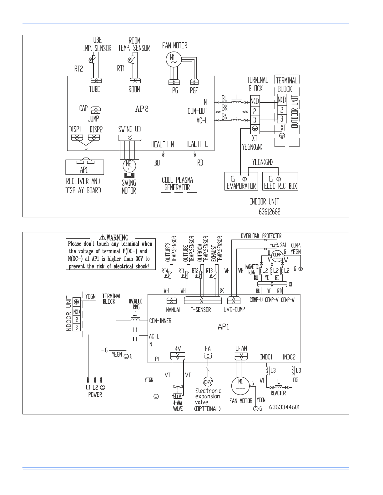
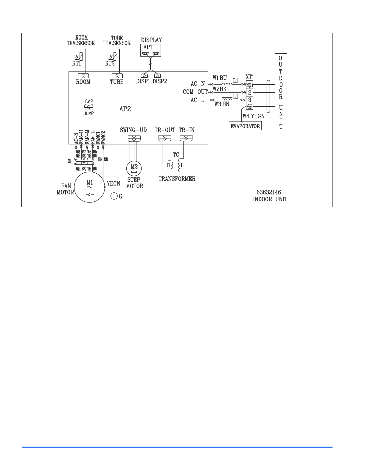
SECTION XXII: TYPICAL UNIT WIRING
DIAGRAM
The indoor unit wiring diagram is located on the inside of the cabinet by
the terminal block. It is necessary to remove the front panel from the
unit to see the diagram. The outdoor unit wiring diagram is located on
the underside of the outdoor unit control access cover.
FIGURE 43: 09K & 12K 115V Outdoor Air Conditioners
Johnson Controls Unitary Products 19
Page 20

898841-UIM-B-0113
FIGURE 44: 09K & 12K Outdoor Air Conditioners
FIGURE 45: 18K & 24K 115V Indoor Air Conditioners
20 Johnson Controls Unitary Products
Page 21

898841-UIM-B-0113
FIGURE 46: 18K & 24K Indoor Air Conditioners
FIGURE 47: 18K Outdoor Air Conditioners
Johnson Controls Unitary Products 21
Page 22

898841-UIM-B-0113
FIGURE 48: 18K Indoor Air Conditioners
FIGURE 49: 24K Outdoor Air Conditioners
22 Johnson Controls Unitary Products
Page 23

898841-UIM-B-0113
FIGURE 50: 24K Indoor Air Conditioners
FIGURE 51: 36K Outdoor Air Conditioners
Johnson Controls Unitary Products 23
Page 24

898841-UIM-B-0113
FIGURE 52: 36K Indoor Air Conditioners
FIGURE 53: 09K & 12K 115V Outdoor Heat Pumps
24 Johnson Controls Unitary Products
Page 25

898841-UIM-B-0113
FIGURE 54: 09K & 12K Outdoor Heat Pumps
FIGURE 55: 18K & 24K 115V Heat Pumps
Johnson Controls Unitary Products 25
Page 26
898841-UIM-B-0113
FIGURE 56: 18K & 24K Indoor Heat Pumps
FIGURE 57: 18K Outdoor Heat Pumps
26 Johnson Controls Unitary Products
Page 27

898841-UIM-B-0113
FIGURE 58: 18K Indoor Heat Pumps
FIGURE 59: 24K Outdoor Heat Pumps
Johnson Controls Unitary Products 27
Page 28

898841-UIM-B-0113
FIGURE 60: 24K Indoor Heat Pumps
FIGURE 61: 30K Outdoor Heat Pumps
28 Johnson Controls Unitary Products
Page 29

898841-UIM-B-0113
FIGURE 62: 30K Indoor Heat Pumps
FIGURE 63: 36K Outdoor Heat Pumps
Johnson Controls Unitary Products 29
Page 30
898841-UIM-B-0113
FIGURE 64: 36K Indoor Heat Pumps
30 Johnson Controls Unitary Products
Page 31

898841-UIM-B-0113
72
HEAT INDICATOR
COOL INDICATOR
TEMPERATURE*
RUN
DEHUMIDIFY
MODE
INFRARED
SIGNAL
RECEIVER
* The temperature readout (either
temperature setpoint or indoor ambient)
will be replaced by an error code if there
is a malfunction. If multiple errors are
detected, the display will alternate
between each error code.
NOTE:
No history is kept on past error codes.
YELLOW LED
GREEN LED
RED LED
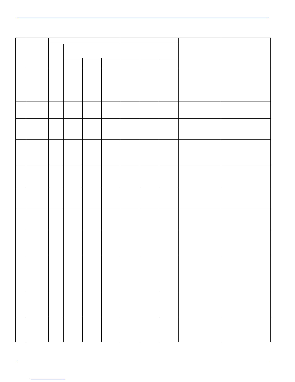
SECTION XXIII: INDOOR AND OUTDOOR UNITS ERROR CODES
This section identifies error codes that appear on the front panel of the indoor unit or outdoor unit control. Many of the error codes w ill automatically
clear themselves when the error no longer exists. However some error codes may require disconnecting power to the system at the unit disconnect
switch or circuit breaker in order to clear them and to resume normal system operation.
FIGURE 65: Indoor Unit Front Panel Indicators
FIGURE 66: Control Board
Johnson Controls Unitary Products 31
Page 32
898841-UIM-B-0113
INDOOR UNIT ERROR CODES
TABLE 12:
No.
1
2
3
4
5
6
7
8
9
10
11
Error Codes - 09K 12K
Malfunction
Name
High
pressure
protection of
system
Antifreezing
protection
System block
or refrigerant
leakage
High
discharge
temperature
protection of
compressor
Overcurrent
protection
Communi-
cation
Malfunction
High
temperature
resistant
protection
EEPROM
malfunction
Limit/
decrease
frequency
due to high
temperature
of module
Malfunction
protection of
jumper cap
Gathering
refrigerant
Dual 8
Code
Display
Display Method of Indoor Unit Malfunction
Indicator Display
ON 0.5s and OFF 0.5s)
Operation
Indicator
OFF 3s
E1
and blink
once
OFF 3S
E2
and blink
twice
OFF 3S
E3
and blink
3 times
OFF 3S
E4
and blink
4 times
OFF 3S
E5
and blink
5 times
OFF 3S
E6
and blink
6 times
OFF 3S
E8
and blink
8 times
EE
EU
OFF 3S
C5
and blink
15 times
OFF 3S
F0
and blink
1 times
(during blinking,
Cool
Indicator
OFF 3S
and blink
6 times
OFF 3S
and blink
1 times
Heating
Indicator
OFF 3S
and blink
15 times
OFF 3S
and blink
6 times
Indicator has 3 kinds of display
status and during blinking, ON 0.5s
Indicator
OFF 3S
and blink
OFF 3S
and blink
OFF 3S
and blink
OFF 3S
and blink
OFF 3S
and blink
11 times
Yellow
3 times
7 times
5 times
6 times
and OFF 0.5s
Red
Indicator
OFF3S
and blink
9 times
Green
Indicator
OFF
A/C Status Possible Causes
During cooling and drying
operation, except indoor
fan operates, all loads
stop operation. During
heating operation, the
complete unit stops.
During cooling and drying
operation, compressor
and outdoor fan stop while
indoor fan operates.
The Dual-8 Code Display
will show E3 until the low
pressure switch stop
operation.
During cooling and drying
operation, compressor
and outdoor fan stop while
indoor fan operates.
During heating operation,
all loads stop.
During cooling and drying
operation, compressor
and outdoor fan stop while
indoor fan operates.
During heating operation,
all loads stop.
During cooling operation,
compressor stops while
indoor fan motor operates.
During heating operation,
the complete unit stops.
During cooling operation:
compressor will stop while
indoor fan will operate.
During heating operation,
the complete unit stops.
During cooling and drying
operation, compressor will
stop while indoor fan will
operate; During heating
operation, the complete
unit will stop.
All loads operate normally,
while operation frequency
for compressor is
decreased
Wireless remote receiver
and button are effective,
but cannot dispose the
related command.
When the outdoor unit
receive signal of Gathering refrigerant, the system
will be forced to run under
cooling mode for gathering
refrigerant
Possible reasons:
1. Refrigerant was super abundant;
2. Poor heat exchange (including filth blockage of heat
exchanger and bad radiating
environment); Ambient temperature is too high.
1. Poor air-return in indoor unit;
2. Fan speed is abnormal;
3. Evaporator is dirty.
1.Low-pressure protection
2.Low-pressure protection of
system
3.Low-pressure protection of
compressor.
Please refer to the ProficienTECH Ductless Splits Technical
Training Manual (discharge protection, overload).
1. Supply voltage is unstable;
2. Supply voltage is too low and
load is too high;
3. Evaporator is dirty.
Refer to the corresponding
ProficienTECH Ductless Splits
Technical Training Manual.
Refer to the malfunction
analysis (overload, high
temperature resistant).
Replace outdoor control panel
AP1.
Discharging after the comple t e
unit is de-energized for 20 mins,
check whether the thermal
grease on IPM Module of
outdoor control panel AP1 is
sufficient and whether the
radiator is inserted tightly. If its
no use, please replace control
panel AP1.
1. No jumper cap insert on
mainboard.
2. Incorrect insert of jumper cap.
3. Jumper cap damaged.
4. Abnormal detecting circuit of
mainboard.
Nominal cooling mode
32 Johnson Controls Unitary Products
Page 33
898841-UIM-B-0113
TABLE 12:
Malfunction
No.
ambient
temperature
12
sensor is
open/short
circuited
evaporator
temperature
13
sensor is
open/short
circuited
Outdoor
ambient
temperature
14
sensor is
open/short
circuited
Outdoor
condenser
temperature
15
sensor is
open/short
circuited
Outdoor
discharge
temperature
16
sensor is
open/short
circuited
decrease
17
frequency
overload
Decrease
frequency
18
overcurrent
Decrease
frequency
19
due to high
air discharge
decrease
20
frequency
antifreezing
Voltage for
21
DC bus-bar is
too high
Error Codes - 09K 12K (Continued)
Display Method of Indoor Unit Malfunction
Indicator Display
Name
Indoor
Indoor
Limit/
due to
due to
Limit/
due to
Dual 8
Code
Display
F1
F2
F3
F4
F5
F6
F8
F9
FH
PH
(during blinking,
ON 0.5s and OFF 0.5s)
Operation
Indicator
Cool
Indicator
OFF 3S
and blink
once
OFF 3S
and blink
twice
OFF 3S
and blink
3 times
OFF 3S
and blink
4 times
OFF 3S
and blink
5 times
OFF 3S
and blink
for 6 times
OFF 3S
and blink
8 times
OFF 3S
and blink
9 times
OFF 3S
and blink
2 times
OFF 3S
and blink
11 times
Heating
Indicator
OFF 3S
and blink
2 times
Indicator has 3 kinds of display
status and during blinking, ON 0.5s
Indicator
OFF 3S
and blink
13 times
Yellow
and OFF 0.5s
Red
Indicator
OFF 3S
and blink
6 times
OFF 3S
and blink
5 times
OFF 3S
and blink
7 times
OFF 3S
and blink
3 times
OFF 3S
and blink
once
OFF 3S
and blink
twice
OFF 3S
and blink
4 times
Green
Indicator
A/C Status Possible Causes
1. Loosening or bad contact of
During cooling and drying
operation, indoor unit
operates while other loads
will stop; during heating
operation, the complete
unit will stop operation.
AC stops operation once
reaches the setting temperature. Cooling, drying:
internal fan motor stops
operation while other
loads stop operation; heating: AC stop operation
During cooling and drying
operating, compressor
stops while indoor fan
operates; During heating
operation, the complete
unit will stop operation.
During cooling and drying
operation, compressor
stops while indoor fan will
operate; During heating
operation, the complete
unit will stop operation.
During cooling and drying
operation, compressor will
stop after operating for
about 3 mins,while indoor
fan will operate;During
heating operation, the
complete unit will stop
after operating for about
3 mins.
All loads operate normally,
while operation frequency
for compressor is
decreased.
All loads operate normally,
while operation frequency
for compressor is
decreased.
All loads operate normally,
while operation frequency
for compressor is
decreased.
All loads operate normally,
while operation frequency
for compressor is
decreased.
During cooling and drying
operation, compressor will
stop while indoor fan will
operate; During heating
operation, the complete
unit will stop operation.
indoor ambient temp. sensor
and mainboard terminal.
2. Components in mainboard fell
down leads short circuit.
3. Indoor ambient temp. sensor
damaged. (check with sensor
resistance value chart).
4. Mainboard damaged.
1. Loosening or bad contact of
Indoor evaporator temp. sensor
and mainboard terminal.
2. Components on the
mainboard fall down leads
short circuit.
3. Indoor evaporator temp.
sensor damaged. (check temp.
sensor value chart for testing).
4. Mainboard damaged.
Outdoor temperature sensor
hasnt been connected well or is
damaged. Please check it by
referring to the resistance table
for temperature sensor).
Outdoor temperature sensor
hasnt been connected well or is
damaged. Please check it by
referring to the resistance table
for temperature sensor).
1.Outdoor temperature sensor
hasnt been connected well or is
damaged. Please check it by
referring to the resistance table
for temperature sensor).
2.The head of temperature
sensor hasnt been inserted
into the copper tube.
Refer to the malfunction
analysis (overload, high
temperature resistant)
The input supply voltage is too
low; System pressure is too high
and overload.
Overload or temperature is too
high; Refrigerant is insufficient;
Malfunction of electric expansion valve (EKV).
Poor air-return in indoor unit or
fan speed is too low.
1. Measure the voltage of position L and N on wiring board
(XT), if the voltage is higher than
265VAC, turn on the unit after
the supply voltage is increased
to the normal range.
2.If the AC input is normal, measure the voltage of electrolytic
capacitor C on control panel
(AP1), if its normal, theres malfunction for the circuit, please
replace the control panel (AP1).
Johnson Controls Unitary Products 33
Page 34

898841-UIM-B-0113
TABLE 12:
Malfunction
No.
Voltage of DC
22
bus-bar is too
Compressor
23
frequence in
test state
Compressor
24
frequence in
test state
Compressor
maximum
25
frequence in
test state
Compressor
intermediate
26
frequence in
test state
Overcurrent
protection
27
of phase
current for
compressor
Charging
28
malfunction
of capacitor
Malfunction
of module
29
temperature
sensor circuit
Module high
30
temperature
protection
Decrease
frequency
due to high
31
temperature
resistant
during heat-
ing operation
32
dedusting
protection
Error Codes - 09K 12K (Continued)
Display Method of Indoor Unit Malfunction
Indicator Display
Name
low
Min
rated
Static
Dual 8
Code
Display
PL
P0
P1
P2
P3
P5
PU
P7
P8
H0
H2
(during blinking,
ON 0.5s and OFF 0.5s)
Operation
Indicator
Cool
Indicator
OFF 3S
and blink
15 times
Heating
Indicator
OFF 3S
and blink
21 times
OFF 3S
and blink
17 times
OFF 3S
and blink
18 times
OFF 3S
and blink
19 times
OFF 3S
and blink
10 times
OFF 3S
and blink
twice
Indicator has 3 kinds of display
status and during blinking, ON 0.5s
Indicator
OFF 3S
and blink
12 times
Yellow
and OFF 0.5s
Red
Indicator
Green
Indicator
A/C Status Possible Causes
1. Measure the voltage of position L and N on wiring board
During cooling and drying
operation, compressor will
stop while indoor fan will
operate; During heating
operation, the complete
unit will stop.
During cooling and drying
operation, compressor will
stop while indoor fan will
operate; During heating
operation, the complete
unit will stop operation.
During cooling and drying
operation, compressor will
stop while indoor fan will
operate; During heating
operation, the complete
unit will stop.
During cooling and drying
operation, compressor will
stop while indoor fan will
operate; During heating
operation, the complete
unit will stop.
During cooling operation,
compressor will stop while
indoor fan will operate;
During heating operation,
the complete unit will stop.
All loads operate normally,
while operation frequency
for compressor is
decreased.
(XT), if the voltage is higher than
150VAC, turn on the unit after
the supply voltage is increased
to the normal range.
2.If the AC input is normal, measure the voltage of electrolytic
capacitor C on control panel
(AP1), if its normal, theres malfunction for the circuit, please
replace the control panel (AP1).
Showing during min. cooling or
min. heating test.
Showing during nominal cooling
or nominal heating test.
Showing during max. cooling or
max. heating test.
Showing during middle cooling
or middle heating test.
Refer to the ProficienTECH
Ductless Splits Technical Training Manual (IPM protection, loss
of synchronism protection and
overcurrent protection of phase
current for compressor..
Refer to the part three-charging
ProficienTECH Ductless Splits
Technical Training Manual of
capacitor.
Replace outdoor control panel
AP1.
After the complete unit is
de-energized for 20 mins, check
whether the thermal grease on
IPM Module of outdoor control
panel AP1 is sufficient and
whether the radiator is inserted
tightly. If its no use, please
replace control panel AP1.
Refer to the ProficienTECH
Ductless Splits Technical Training Manual (overload, high temperature resistant).
34 Johnson Controls Unitary Products
Page 35

898841-UIM-B-0113
TABLE 12:
Malfunction
No.
Overload
33
protection for
compressor
System is
34
abnormal
35
protection
Module
36
temperature
is too high
Internal
37
(fan motor)
operate
Desynchro-
38
nizing of
compressor
39
protection
Outdoor DC
40
fan motor
malfunction
41
protection
Indoor unit
and outdoor
42
unit doesn't
43
start-up
Malfunction
of phase
current
44
detection
circuit for
compressor
Error Codes - 09K 12K (Continued)
Display Method of Indoor Unit Malfunction
Indicator Display
Name
IPM
motor
do not
PFC
Power
match
Failure
Dual 8
Code
Display
H3
H4
H5
H5
H6
H7
HC
L3
L9
LP
LC
U1
(during blinking,
ON 0.5s and OFF 0.5s)
Operation
Indicator
OFF 3S
and blink
11 times
OFF 3S
and blink
23 times
OFF 3S
and blink
20 times
OFF 3S
and blink
19 times
Cool
Indicator
Heating
Indicator
OFF 3S
and blink
3 times
OFF 3S
and blink
4 times
OFF 3S
and blink
5 times
OFF 3S
and blink
5 times
OFF 3S
and blink
7 times
OFF 3S
and blink
6 times
OFF 3S
and blink
11 times
OFF 3S
and blink
13 times
Indicator has 3 kinds of display
status and during blinking, ON 0.5s
Indicator
OFF 3S
and blink
OFF 3S
and blink
OFF 3S
and blink
OFF 3S
and blink
10 times
OFF 3S
and blink
14 times
OFF 3S
and blink
OFF 3S
and blink
16 times
Yellow
8 times
6 times
4 times
9 times
and OFF 0.5s
Red
Indicator
OFF 3S
and blink
14 times
Green
Indicator
A/C Status Possible Causes
During cooling and drying
operation, compressor will
stop while indoor fan will
operate; During heating
operation, the complete
unit will stop operation.
During cooling and drying
operation, compressor will
stop while indoor fan will
operate; During heating
operation, the complete
unit will stop operation.
During cooling and drying
operation, compressor will
stop while indoor fan will
operate; During heating
operation, the complete
unit will stop operation.
Internal fan motor , external fan motor, compressor
and electric heater stop
operation, guide louver
stops at present location.
During cooling and drying
operation, compressor will
stop while indoor fan will
operate; During heating
operation, the complete
unit will stop operation.
During cooling and drying
operation, compressor will
stop while indoor fan will
operate; During heating
operation, the complete
unit will stop operation.
Outdoor DC fan motor
malfunction lead to compressor stop operation.
Compressor stop operation and Outdoor fan
motor will stop 30s latter,
3 minutes latter fan motor
and compressor will
restart.
compressor and Outdoor
fan motor can’t work.
During cooling and drying
operation, compressor will
stop while indoor fan will
operate; During heating
operation, the complete
unit will stop operation.
During cooling and drying
operation, compressor will
stop while indoor fan will
operate; During heating
operation, the complete
unit will stop.
1. Wiring terminal OVC-COMP
is loosened. In normal state, the
resistance for this terminal
should be less than 1ohm.
2. Refer to the ProficienTECH
Ductless Splits Technical Training Manual ( discharge protection, overload).
Refer to the ProficienTECH
Ductless Splits Technical Training Manual (overload, high temperature resistant).
Refer to the ProficienTECH
Ductless Splits Technical Training Manual (IPM protection, loss
of synchronism protection and
overcurrent protection of phase
current for compressor.
1. Bad contact of DC motor
feedback terminal.
2. Bad contact of DC motor
control end.
3. Fan motor is stalling.
4. Motor malfunction.
5. Malfunction of mainboard rev
detecting circuit.
Refer to the ProficienTECH
Ductless Splits Technical Training Manual (IPM protection, loss
of synchronism protection and
overcurrent protection of phase
current for compressor.
Refer to the ProficienTECH
Ductless Splits Technical Training Manual.
DC fan motor malfunction or
system blocked or the connector
loosed
To protect the electronical
components when detect high
power.
Indoor unit and outdoor unit
doesn't match.
Refer to the ProficienTECH
Ductless Splits Technical Training Manual.
Replace outdoor control panel
AP1.
Johnson Controls Unitary Products 35
Page 36

898841-UIM-B-0113
TABLE 12:
Malfunction
No.
Name
Malfunction
of voltage
45
dropping for
DC bus-bar
Malfunction
of complete
46
units current
detection
The four-way
47
valve is
abnormal
Zero-crossing
malfunction
48
of outdoor
unit
Frequency
49
limiting
(power).
Compressor
50
is open-
circuited
The
temperature
51
for turning on
the unit is
reached
Frequency
limiting
52
(module
temperature)
Normal com-
53
munication
54 Defrosting
Error Codes - 09K 12K (Continued)
Display Method of Indoor Unit Malfunction
Indicator Display
Dual 8
Code
Display
U3
U5
U7
U9
(during blinking,
ON 0.5s and OFF 0.5s)
Operation
Indicator
OFF 3S
and blink
18 times
Indicator
OFF 3S
and blink
13 times
OFF 3S
and blink
20 times
Cool
Heating
Indicator
OFF 3S
and blink
20 times
OFF 3S
and blink
once
(during
blinking,
ON 10s
and OFF
0.5s)
Indicator has 3 kinds of display
status and during blinking, ON 0.5s
Indicator
OFF 3S
and blink
OFF 3S
and blink
Yellow
once
twice
and OFF 0.5s
Red
Indicator
OFF 3S
and blink
13 times
OFF 3S
and blink
8 times
OFF 3S
and blink
11 times
Green
Indicator
Continously
A/C Status Possible Causes
During cooling and drying
operation, compressor will
stop while indoor fan will
operate; During heating
operation, the complete
unit will stop
During cooling and drying
operation, the compressor will stop while indoor
fan will operate; During
heating operating, the
complete unit will stop
operation.
If this malfunction occurs
during heating operation,
the complete unit will stop
operation.
During cooling operation,
compressor will stop while
indoor fan will operate;
during heating,the complete unit will stop operation.
Defrosting will occur in
heating mode. Compressor will operate while
indoor fan will stop operation.
Supply voltage is unstable
Theres circuit malfunction on
outdoor units control panel AP1,
please replace the outdoor units
control panel AP1.
1. Supply voltage is lower than
AC175V;
2. Wiring terminal 4V is loosened or broken;
3. 4V is damaged, please
replace 4V.
Replace outdoor control panel
AP1.
Its the normal state.
36 Johnson Controls Unitary Products
Page 37
898841-UIM-B-0113
TABLE 13:
Malfunction
No.
High pressure
1
Antifreezing
2
High discharge
temperature
3
protection of
compressor
Overcurrent
4
Communication
5
Malfunction
temperature
6
motor (indoor
fan) has circuit
7
malfunction
by zero cross
(indoor fan
8
motor) does
not operate
Malfunction
9
protection of
jumper cap
Indoor ambient
temperature
10
sensor is open/
short circuited
Indoor evapora-
tor temperature
11
sensor is open/
short circuited
12
temperature
sensor is open/
short circuited
Error Codes - 18K 24K
Name
protection
of system
protection
protection
High
resistant
protection
Circuit PG
detection
PG motor
Outdoor
ambient
Dual-8
Code
Display
E1
E2
E4
E5
E6
E8
U8
H6
C5
F1
F2
F3
Display Method of Indoor Unit
Indicator Display (during
blinking,
ON 0.5s and OFF 0.5s)
Operation
Indicator
OFF 3s and
blink once
OFF 3S
and blink
twice
OFF 3S
and blink
4 times
OFF 3S
and blink
5 times
OFF 3S
and blink 6
times
OFF 3S
and blink
8 times
OFF 3S
and blink
for 17 times
OFF 3S
and blink
11 times
OFF 3S
and blink
15 times
Cool
Indicator
OFF 3S
and blink
once
OFF 3S
and blink
twice
OFF 3S
and blink
3 times
Heating
Indicator
Display Method of Outdoor
Unit (Indicator has 3 kinds of
display status and they will
be repeated every 5s.)
□ OFF
■ Illuminated
☆ Blink
D5
D6
D16
(D40)
(D41)
(D42)
D30
(D43)
□☆☆☆
■□■□
■□■☆
□■☆□
□□□☆
■□■■
□□☆■
A/C status Possible Reasons
During cooling and drying
operation, except indoor fan
operates, all loads stop
operation. During heating
operation, the complete
unit stops.
During cooling and drying
operation, compressor and
outdoor fan stop while indoor
fan operates.
During cooling and drying
operation, compressor and
outdoor fan stop while indoor
fan operates. During heating
operation, all loads stop.
During cooling and drying
operation, compressor and
outdoor fan stop while indoor
fan operates. During heating
operation, all loads stop.
During cooling operation,
compressor stops while
indoor fan motor operates.
During heating operation,
the complete unit stops.
During cooling operation:
compressor will stop while
indoor fan will operate.
During heating operation,
the complete unit stops.
Operation of remote
controller or control panel is
available, but the unit wont
act.
The complete unit will stop
operation.
The complete unit will stop
operation.
During cooling and drying
operation, indoor unit
operates while other loads
will stop; during heating
operation, the complete
unit will stop operation.
During cooling and drying
operation, indoor unit will
operate while other loads
will stop; During heating
operation, the complete
unit will stop operation.
During cooling and drying
operating, compressor stops
while indoor fan operates;
During heating operation,
the complete unit will stop
operation.
Possible reasons:
1. Refrigerant was overcharged;
2. Poor heat exchange (including
filth blockage of heat exchanger
and bad radiating environment);
Ambient temperature is too high.
1. Poor air-return in indoor unit;
2. Fan speed is abnormal;
3. Evaporator is dirty.
Please refer to the ProficienTECH
Ductless Splits Technical Training
Manual (discharge protection,
overload).
1. Supply voltage is unstable;
2. Supply voltage is too low an
load is too high;
3. Evaporator is dirty.
Refer to the corresponding
ProficienTECH Ductless Splits
Technical Training Manual.
Refer to the ProficienTECH Ductless Splits Technical Training Manual
(overload, high temperature
resistant).
Control board is damaged.
Poor connection for PGF in circuit
diagram;
Malfunction of indoor units control
panel AP1;
Malfunction of indoor units motor
M1.
Poor connection for the jumper cap
on indoor units control panel AP1;
please reinsert or replace the
jumper cap;
1.Room temperature sensor hasn’t
been connected well with indoor
units control panel AP1 (refer to
the wiring diagram for indoor unit);
2.Room temperature sensor is
damaged (please refer to the resistance table of temperature sensor)
1.Room temperature sensor hasn’t
been connected well with indoor
units control panel AP1 (refer to
the wiring diagram for indoor unit);
2.Room temperature sensor is
damaged (please refer to the resistance table of temperature sensor)
Outdoor temperature sensor
hasn’t been connected well or is
damaged. Please check it by
referring to the resistance table
for temperature sensor).
Johnson Controls Unitary Products 37
Page 38

898841-UIM-B-0113
TABLE 13:
No.
13
14
15
16
17
18
19
20
21 Defrosting H1
22
23
Error Codes - 18K 24K (Continued)
Malfunction
Name
Outdoor
condenser
temperature
sensor is open/
short circuited
Outdoor
discharge
temperature
sensor is open/
short circuited
Limit/ decrease
frequency
due to overload
Decrease
frequency due
to overcurrent
Decrease
frequency due
to high air
discharge
Voltage for
DC bus-bar
is too high
Malfunction of
complete units
current
detection
Overcurrent
protection of
phase current
for compressor
Static
de-dusting
protection
Overload
protection for
compressor
Display Method of Indoor Unit
Indicator Display (during
Dual-8
Code
Display
F4
F5
F6
F8
F9
PH
U5
P5
H2
H3
Operation
Indicator
blinking,
ON 0.5s and OFF 0.5s)
Indicator
OFF 3S
and blink
4 times
OFF 3S
and blink
5 times
OFF 3S
and blink
OFF 3S
and blink
8 times
OFF 3S
and blink
9 times
OFF 3S
and blink
11 times
OFF 3S
and blink
13 times
OFF 3S
and blink
15 times
Cool
for 6
times
Heating
Indicator
OFF 3S
and blink
once
OFF 3S
and blink
twice
OFF 3S
and blink
3 times
Display Method of Outdoor
Unit (Indicator has 3 kinds of
display status and they will
be repeated every 5s.)
□ OFF
■ Illuminated
☆ Blink
D5
D6
D16
(D40)
(D41)
(D42)
D30
(D43)
□□☆□
□□☆☆
■□☆☆
■■□■
■■□□
□■□☆
□■☆■
□☆□□
□☆☆□
A/C status Possible Reasons
During cooling and drying
operation, compressor stops
while indoor fan will
operate; During heating
operation the complete unit
will stop operation.
During cooling and drying
operation, compressor will
stop after operating for about
3 mins, while indoor fan will
operate; During heating
operation, the complete unit
will stop after operating for
about 3 mins.
All loads operate normally,
while operation frequency for
compressor is decreased.
All loads operate normally,
while operation frequency for
compressor is decreased.
All loads operate normally,
while operation frequency for
compressor is decreased.
During cooling and drying
operation, compressor will
stop while indoor fan will
operate; During heating
operation, the complete
unit will stop operation.
During cooling and drying
operation, the compressor
will stop while indoor fan
will operate; During heating
operating, the complete
unit will stop operation.
During cooling and drying
operation, compressor will
stop while indoor fan will
operate; During heating
operation, the complete
unit will stop operation.
Defrosting will occur in
heating mode. Compressor
will operate while indoor fan
will stop operation.
//
During cooling and drying
operation, compressor will
stop while indoor fan will
operate; During heating
operation, the complete
unit will stop operation.
Outdoor temperature sensor
hasn’t been connected well or is
damaged. Please check it by
referring to the resistance table
for temperature sensor).
1.Outdoor temperature sensor
hasn’t been connected well or is
damaged. Please check it by
referring to the resistance table for
temperature sensor).
2.The head of temperature sensor
hasn’t been inserted into the
copper tube.
Refer to the ProficienTECH Ductless Splits Technical Training Manual (overload, high temperature
resistant).
The input supply voltage is too low;
System pressure is too high and
overload.
Overload or temperature is too
high; Refrigerant is insufficient;
Malfunction of electric expansion
valve (EKV).
1. Measure the voltage of position
L and N on wiring board (XT), if the
voltage is higher than 265VAC,
turn on the unit after the supply
voltage is increased to the normal
range.
2. If the AC input is normal
measure the voltage of electrolytic
capacitor C on control panel (AP1),
if its normal, there’s malfunction for
the circuit, please replace the control panel (AP1).
There’s circuit malfunctionon outdoor units control panel AP1,
please replace the outdoor units
control panel AP1.
Refer to the ProficienTECH Ductless Splits Technical Training Manual (IPM protection, loss of
synchronism protection and
overcurrent protection of phase
current for compressor.
Its the normal state.
1. Wiring terminal OVC-COMP is
loosened. In normal state, the
resistance for this terminal should
be less than 1ohm.
2.Refer to the ProficienTECH
Ductless Splits Technical Training
Manual (discharge protection,
overload).
38 Johnson Controls Unitary Products
Page 39
898841-UIM-B-0113
TABLE 13:
No.
24
25
26
27
28
29 Failure startup LC
30
31
32
33
Error Codes - 18K 24K (Continued)
Malfunction
Name
System is
abnormal
IPM
protection
PFC
protection
Desynchronizing
of compressor
Decrease
frequency due to
high temperature
resistant during
heating operation
Malfunction of
phase current
detection circuit
for compressor
EE PROM
malfunction
Charging
malfunction of
capacitor
Malfunction
of module
temperature
sensor circuit
Display Method of Indoor Unit
Indicator Display (during
Dual-8
Code
Display
H4
H5
HC
H7
H0
U1
EE
PU
P7
Operation
Indicator
blinking,
ON 0.5s and OFF 0.5s)
Indicator
Cool
Heating
Indicator
OFF 3S
and blink
4 times
OFF 3S
and blink
5 times
OFF 3S
and blink
6 times
OFF 3S
and blink
7 times
OFF 3S
and blink
10 times
OFF 3S
and blink
11 times
OFF 3S
and blink
13 times
OFF 3S
and blink
15 times
OFF 3S
and blink
17 times
OFF 3S
and blink
18 times
Display Method of Outdoor
Unit (Indicator has 3 kinds of
display status and they will
be repeated every 5s.)
□ OFF
■ Illuminated
☆ Blink
D5
D6
D16
(D40)
(D41)
■□■■
□☆□■
□■☆☆
□☆■☆
(D42)
D30
(D43)
■□☆☆
□☆□☆
□☆■□
□□□■
□■□■
□□■☆
A/C status Possible Reasons
During cooling and drying
operation, compressor will
stop while indoor fan will
operate; During heating
operation, the complete
unit will stop operation.
During cooling and drying
operation, compressor will
stop while indoor fan will
operate; During heating
operation, the complete
unit will stop operation.
During cooling and drying
operation, compressor will
stop while indoor fan will
operate; During heating
operation, the complete
unit will stop operation.
During cooling and drying
operation, compressor will
stop while indoor fan will
operate; During heating
operation, the complete
unit will stop operation.
All loads operate normally,
while operation frequency for
compressor is decreased.
During cooling and drying
operation, compressor will
stop while indoor fan will
operate; During heating
operation, the complete
unit will stop operation.
During cooling and drying
operation, compressor will
stop while indoor fan will
operate; During heating
operation, the complete
unit will stop.
During cooling and drying
operation, compressor will
stop while indoor fan will
operate; During heating
operation, the complete
unit will stop.
During cooling and drying
operation, compressor will
stop while indoor fan will
operate; During heating
operation, the complete
unit will stop.
During cooling and drying
operation, compressor will
stop while indoor fan will
operate; During heating
operation, the complete
unit will stop.
Refer to the ProficienTECH Ductless Splits Technical Training Manual (overload, high temperature
resistant)
Refer to the ProficienTECH Ductless Splits Technical Training Manual (IPM protection, loss of
synchronism protection and overcurrent protection of phase current
for compressor.
Refer to the ProficienTECH Ductless Splits Technical Training Manual
Refer to the ProficienTECH Ductless Splits Technical Training Manual (IPM protection, loss of
synchronism protection and overcurrent protection of phase current
for compressor.
Refer to the ProficienTECH Ductless Splits Technical Training Manual (overload, high temperature
resistant).
Refer to the ProficienTECH Ductless Splits Technical Training Manual.
Replace outdoor control panel
AP1.
Replace outdoor control panel
AP1.
Refer to the part three charging
ProficienTECH Ductless Splits
Technical Training Manual of
capacitor.
Replace outdoor control panel
AP1.
Johnson Controls Unitary Products 39
Page 40

898841-UIM-B-0113
TABLE 13:
Malfunction
No.
Module high
34
temperature
Malfunction of
35
voltage dropping
for DC bus-bar
Voltage of DC
36
Limit/ decrease
frequency due to
37
high temperature
The four-way
38
valve is abnormal
Zero crossing
39
malfunction of
outdoor unit
Limit/ decrease
40
frequency due to
antifreezing
Error Codes - 18K 24K (Continued)
Display Method of Indoor Unit
Name
protection
bus-bar is
too low
of module
Dual-8
Code
Display
P8
U3
PL
EU
U7
U9
FH
Indicator Display (during
ON 0.5s and OFF 0.5s)
Operation
Indicator
blinking,
Cool
Indicator
Heating
Indicator
OFF 3S
and blink
19 times
OFF 3S
and blink
20 times
OFF 3S
and blink
21 times
Display Method of Outdoor
Unit (Indicator has 3 kinds of
display status and they will
be repeated every 5s.)
□ OFF
■ Illuminated
☆ Blink
D5
D6
D16
(D40)
(D41)
(D42)
D30
(D43)
■□☆■
□■■■
□■■□
■■■☆
■□☆□
■■☆□
■■■□
A/C status Possible Reasons
After the complete unit is
During cooling operation,
compressor will stop while
indoor fan will operate;
During heating operation,
the complete unit will stop.
During cooling and drying
operation, compressor will
stop while indoor fan will
operate; During heating
operation, the complete
unit will stop.
During cooling and drying
operation, compressor will
stop while indoor fan will
operate; During heating
operation, the complete
unit will stop.
All loads operate normally,
while operation frequency
for compressor is decreased.
If this malfunction occurs
during heating operation,
the complete unit will stop
operation.
During cooling operation,
compressor will stop while
indoor fan will operate;
during heating, the complete
unit will stop operation.
All loads operate normally,
while operation frequency for
compressor is decreased.
de-energized for 20mins, check
whether the thermal grease on
IPM Module of outdoor control
panel AP1 is sufficient and whether
the radiator is inserted tightly. If its
no use, please replace control
panel AP1.
Supply voltage is unstable.
1. Measure the voltage of position
L and N on wiring board (XT), if the
voltage is higher than 150VAC,
turn on the unit after the supply
voltage is increased to the normal
range.
2.If the AC input is normal,
measure the voltage of electrolytic
capacitor C on control panel (AP1),
if its normal, there’s malfunction for
the circuit, please replace the
control panel (AP1).
Discharging after the complete unit
is de-energized for 20mins, check
whether the thermal grease on
IPM Module of outdoor control
panel AP1 is sufficient and whether
the radiator is inserted tightly. If its
no use, please replace control
panel AP1.
1.Supply voltage is lower than
AC175V;
2.Wiring terminal 4V is loosened
or broken; 3.4V is damaged,
please replace 4V.
Replace outdoor control panel
AP1.
Poor air-return in indoor unit or
fan speed is too low.
40 Johnson Controls Unitary Products
Page 41

898841-UIM-B-0113
TABLE 14:
Malfunction
No.
pressure
1
protection of
system
Antifreezing
2
protection
System block
3
or refrigerant
leakage
discharge
4
temperature
protection of
compressor
Overcurrent
5
protection
Communi-
6
Malfunction
temperature
7
resistant
protection
EEPROM
8
malfunction
decrease
frequency
9
due to high
temperature
of module
Malfunction
10
protection of
jumper cap
Gathering
11
refrigerant
Error Codes - 30K 36K
Display Method of Indoor Unit Malfunction
Name
High
High
cation
High
Limit/
Dual 8
Code
Display
E1
E2
E3
E4
E5
E6
E8
EE
EU
C5
F0
Indicator Display
(during blinking,
ON 0.5s and OFF 0.5s)
Operation
Indicator
OFF 3s
and blink
once
OFF 3S
and blink
twice
OFF 3S
and blink
3 times
OFF 3S
and blink
4 times
OFF 3S
and blink
5 times
OFF 3S
and blink
6 times
OFF 3S
and blink
8 times
OFF 3S
and blink
15 times
OFF 3S
and blink
1 times
Indicator
OFF 3S
and blink
6 times
OFF 3S
and blink
1 times
Cool
Heating
Indicator
OFF 3S
and blink
15 times
OFF 3S
and blink
6 times
Indicator has 3 kinds of display
status and during blinking, ON 0.5s
Indicator
OFF 3S
and blink
OFF 3S
and blink
OFF 3S
and blink
OFF 3S
and blink
OFF 3S
and blink
11 times
Yellow
3 times
7 times
5 times
6 times
and OFF 0.5s
Red
Indicator
OFF3S
and blink
9 times
Green
Indicator
OFF
A/C Status Possible Causes
During cooling and drying
operation, except indoor
fan operates, all loads
stop operation. During
heating operation, the
complete unit stops.
During cooling and drying
operation, compressor
and outdoor fan stop while
indoor fan operates.
The Dual-8 Code Display
will show E3 until the low
pressure switch stop
operation.
During cooling and drying
operation, compressor
and outdoor fan stop while
indoor fan operates.
During heating operation,
all loads stop.
During cooling and drying
operation, compressor
and outdoor fan stop while
indoor fan operates.
During heating operation,
all loads stop.
During cooling operation,
compressor stops while
indoor fan motor operates.
During heating operation,
the complete unit stops.
During cooling operation:
compressor will stop while
indoor fan will operate.
During heating operation,
the complete unit stops.
During cooling and drying
operation, compressor will
stop while indoor fan will
operate; During heating
operation, the complete
unit will stop.
All loads operate normally,
while operation frequency
for compressor is
decreased
Wireless remote receiver
and button are effective,
but cannot dispose the
related command.
When the outdoor unit
receive signal of Gathering refrigerant, the system
will be forced to run under
cooling mode for gathering
refrigerant
Possible reasons:
1. Refrigerant was super abundant;
2. Poor heat exchange (including filth blockage of heat
exchanger and bad radiating
environment); Ambient temperature is too high.
1. Poor air-return in indoor unit;
2. Fan speed is abnormal;
3. Evaporator is dirty.
1.Low-pressure protection
2.Low-pressure protection of
system
3.Low-pressure protection of
compressor.
Please refer to the ProficienTECH Ductless Splits Technical
Training Manual (discharge protection, overload).
1. Supply voltage is unstable;
2. Supply voltage is too low and
load is too high;
3. Evaporator is dirty.
Refer to the corresponding
ProficienTECH Ductless Splits
Technical Training Manual.
Refer to the ProficienTECH
Ductless/ (overload, high
temperature resistant).
Replace outdoor control panel
AP1.
Discharging after the complete
unit is de-energized for 20 mins,
check whether the thermal
grease on IPM Module of
outdoor control panel AP1 is
sufficient and whether the
radiator is inserted tightly. If its
no use, please replace control
panel AP1.
1. No jumper cap insert on
mainboard.
2. Incorrect insert of jumper cap.
3. Jumper cap damaged.
4. Abnormal detecting circuit of
mainboard.
Nominal cooling mode
Johnson Controls Unitary Products 41
Page 42
898841-UIM-B-0113
TABLE 14:
Malfunction
No.
ambient
temperature
12
sensor is
open/short
circuited
evaporator
temperature
13
sensor is
open/short
circuited
Outdoor
ambient
temperature
14
sensor is
open/short
circuited
Outdoor
condenser
temperature
15
sensor is
open/short
circuited
Outdoor
discharge
temperature
16
sensor is
open/short
circuited
decrease
17
frequency
overload
Decrease
frequency
18
overcurrent
Decrease
frequency
19
due to high
air discharge
decrease
20
frequency
antifreezing
Voltage for
21
DC bus-bar is
too high
Error Codes - 30K 36K (Continued)
Display Method of Indoor Unit Malfunction
Indicator Display
Name
Indoor
Indoor
Limit/
due to
due to
Limit/
due to
Dual 8
Code
Display
F1
F2
F3
F4
F5
F6
F8
F9
FH
PH
(during blinking,
ON 0.5s and OFF 0.5s)
Operation
Indicator
Cool
Indicator
OFF 3S
and blink
once
OFF 3S
and blink
twice
OFF 3S
and blink
3 times
OFF 3S
and blink
4 times
OFF 3S
and blink
5 times
OFF 3S
and blink
for 6 times
OFF 3S
and blink
8 times
OFF 3S
and blink
9 times
OFF 3S
and blink
2 times
OFF 3S
and blink
11 times
Heating
Indicator
OFF 3S
and blink
2 times
Indicator has 3 kinds of display
status and during blinking, ON 0.5s
Indicator
OFF 3S
and blink
13 times
Yellow
and OFF 0.5s
Red
Indicator
OFF 3S
and blink
6 times
OFF 3S
and blink
5 times
OFF 3S
and blink
7 times
OFF 3S
and blink
3 times
OFF 3S
and blink
once
OFF 3S
and blink
twice
OFF 3S
and blink
4 times
Green
Indicator
A/C Status Possible Causes
1. Loosening or bad contact of
During cooling and drying
operation, indoor unit
operates while other loads
will stop; during heating
operation, the complete
unit will stop operation.
AC stops operation once
reaches the setting temperature. Cooling, drying:
internal fan motor stops
operation while other
loads stop operation; heating: AC stop operation
During cooling and drying
operating, compressor
stops while indoor fan
operates; During heating
operation, the complete
unit will stop operation.
During cooling and drying
operation, compressor
stops while indoor fan will
operate; During heating
operation, the complete
unit will stop operation.
During cooling and drying
operation, compressor will
stop after operating for
about 3 mins,while indoor
fan will operate;During
heating operation, the
complete unit will stop
after operating for about
3 mins.
All loads operate normally,
while operation frequency
for compressor is
decreased.
All loads operate normally,
while operation frequency
for compressor is
decreased.
All loads operate normally,
while operation frequency
for compressor is
decreased.
All loads operate normally,
while operation frequency
for compressor is
decreased.
During cooling and drying
operation, compressor will
stop while indoor fan will
operate; During heating
operation, the complete
unit will stop operation.
indoor ambient temp. sensor
and mainboard terminal.
2. Components in mainboard fell
down leads short circuit.
3. Indoor ambient temp. sensor
damaged. (check with sensor
resistance value chart).
4. Mainboard damaged.
1. Loosening or bad contact of
Indoor evaporator temp. sensor
and mainboard terminal.
2. Components on the
mainboard fall down leads
short circuit.
3. Indoor evaporator temp.
sensor damaged. (check temp.
sensor value chart for testing).
4. Mainboard damaged.
Outdoor temperature sensor
hasnt been connected well or is
damaged. Please check it by
referring to the resistance table
for temperature sensor).
Outdoor temperature sensor
hasnt been connected well or is
damaged. Please check it by
referring to the resistance table
for temperature sensor).
1.Outdoor temperature sensor
hasnt been connected well or is
damaged. Please check it by
referring to the resistance table
for temperature sensor).
2.The head of temperature
sensor hasnt been inserted
into the copper tube.
Refer to the ProficienTECH
Ductless Splits Technical Training Manual (overload, high
temperature resistant)
The input supply voltage is too
low; System pressure is too high
and overload.
Overload or temperature is too
high; Refrigerant is insufficient;
Malfunction of electric expansion valve (EKV).
Poor air-return in indoor unit or
fan speed is too low.
1. Measure the voltage of position L and N on wiring board
(XT), if the voltage is higher than
265VAC, turn on the unit after
the supply voltage is increased
to the normal range.
2.If the AC input is normal, measure the voltage of electrolytic
capacitor C on control panel
(AP1), if its normal, theres malfunction for the circuit, please
replace the control panel (AP1).
42 Johnson Controls Unitary Products
Page 43

898841-UIM-B-0113
TABLE 14:
Malfunction
No.
Voltage of DC
22
bus-bar is too
Compressor
23
frequence in
test state
Compressor
24
frequence in
test state
Compressor
maximum
25
frequence in
test state
Compressor
intermediate
26
frequence in
test state
Overcurrent
protection
27
of phase
current for
compressor
Charging
28
malfunction
of capacitor
Malfunction
of module
29
temperature
sensor circuit
Module high
30
temperature
protection
Decrease
frequency
due to high
31
temperature
resistant
during heat-
ing operation
32
dedusting
protection
Error Codes - 30K 36K (Continued)
Display Method of Indoor Unit Malfunction
Indicator Display
Name
low
Min
rated
Static
Dual 8
Code
Display
PL
P0
P1
P2
P3
P5
PU
P7
P8
H0
H2
(during blinking,
ON 0.5s and OFF 0.5s)
Operation
Indicator
cool mode,
cool mode,
cool mode,
cool mode,
Cool
Indicator
Blinking in
ON 0.25s
and OFF
0.25s
Blinking in
ON 0.25s
and OFF
0.25s
Blinking in
ON 0.25s
and OFF
0.25s
Blinking in
ON 0.25s
and OFF
0.25s
OFF 3S
and blink
15 times
Heating
Indicator
OFF 3S
and blink
21 times
Blinking in
heat mode,
ON 0.25s
and OFF
0.25s
Blinking in
heat mode,
ON 0.25s
and OFF
0.25s
Blinking in
heat mode,
ON 0.25s
and OFF
0.25s
Blinking in
heat mode,
ON 0.25s
and OFF
0.25s
OFF 3S
and blink
17 times
OFF 3S
and blink
18 times
OFF 3S
and blink
19 times
OFF 3S
and blink
10 times
OFF 3S
and blink
twice
Indicator has 3 kinds of display
status and during blinking, ON 0.5s
Indicator
OFF 3S
and blink
12 times
Yellow
and OFF 0.5s
Red
Indicator
Green
Indicator
A/C Status Possible Causes
1. Measure the voltage of position L and N on wiring board
During cooling and drying
operation, compressor will
stop while indoor fan will
operate; During heating
operation, the complete
unit will stop.
During cooling and drying
operation, compressor will
stop while indoor fan will
operate; During heating
operation, the complete
unit will stop operation.
During cooling and drying
operation, compressor will
stop while indoor fan will
operate; During heating
operation, the complete
unit will stop.
During cooling and drying
operation, compressor will
stop while indoor fan will
operate; During heating
operation, the complete
unit will stop.
During cooling operation,
compressor will stop while
indoor fan will operate;
During heating operation,
the complete unit will stop.
All loads operate normally,
while operation frequency
for compressor is
decreased.
(XT), if the voltage is higher than
150VAC, turn on the unit after
the supply voltage is increased
to the normal range.
2.If the AC input is normal, measure the voltage of electrolytic
capacitor C on control panel
(AP1), if its normal, theres malfunction for the circuit, please
replace the control panel (AP1).
Showing during min. cooling or
min. heating test.
Showing during nominal cooling
or nominal heating test.
Showing during max. cooling or
max. heating test.
Showing during middle cooling
or middle heating test.
Refer to the ProficienTECH
Ductless Splits Technical Training Manual (IPM protection, loss
of synchronism protection and
overcurrent protection of phase
current for compressor..
Refer to the part three-charging
ProficienTECH Ductless Splits
Technical Training Manual of
capacitor.
Replace outdoor control panel
AP1.
After the complete unit is
de-energized for 20 mins, check
whether the thermal grease on
IPM Module of outdoor control
panel AP1 is sufficient and
whether the radiator is inserted
tightly. If its no use, please
replace control panel AP1.
Refer to the ProficienTECH
Ductless Splits Technical Training Manual (overload, high temperature resistant).
Johnson Controls Unitary Products 43
Page 44

898841-UIM-B-0113
TABLE 14:
Malfunction
No.
Overload
33
protection for
compressor
temperature
34
resistant
protection
35
protection
Module
36
temperature
is too high
Internal
37
(fan motor)
operate
Desynchro-
38
nizing of
compressor
39
protection
Outdoor DC
40
fan motor
malfunction
41
protection
Indoor unit
and outdoor
42
unit doesn't
43
start-up
Malfunction
of phase
44
detection
circuit for
compressor
Error Codes - 30K 36K (Continued)
Display Method of Indoor Unit Malfunction
Indicator Display
Name
High
IPM
motor
do not
PFC
Power
match
Failure
current
Dual 8
Code
Display
H3
H4
H5
H5
H6
H7
HC
L3
L9
LP
LC
U1
(during blinking,
ON 0.5s and OFF 0.5s)
Operation
Indicator
OFF 3S
and blink
11 times
OFF 3S
and blink
23 times
OFF 3S
and blink
20 times
OFF 3S
and blink
19 times
Cool
Indicator
Heating
Indicator
OFF 3S
and blink
3 times
OFF 3S
and blink
4 times
OFF 3S
and blink
5 times
OFF 3S
and blink
5 times
OFF 3S
and blink
7 times
OFF 3S
and blink
6 times
OFF 3S
and blink
11 times
OFF 3S
and blink
13 times
Indicator has 3 kinds of display
status and during blinking, ON 0.5s
Indicator
OFF 3S
and blink
OFF 3S
and blink
OFF 3S
and blink
OFF 3S
and blink
10 times
OFF 3S
and blink
14 times
OFF 3S
and blink
OFF 3S
and blink
16 times
Yellow
8 times
6 times
4 times
9 times
and OFF 0.5s
Red
Indicator
OFF 3S
and blink
14 times
Green
Indicator
A/C Status Possible Causes
During cooling and drying
operation, compressor will
stop while indoor fan will
operate; During heating
operation, the complete
unit will stop operation.
During cooling operation,
compressor stops while
indoor fan motor operates.
During heating operation,
the complete unit stops.
During cooling and drying
operation, compressor will
stop while indoor fan will
operate; During heating
operation, the complete
unit will stop operation.
Internal fan motor, external fan motor, compressor
and electric heater stop
operation, guide louver
stops at present location.
During cooling and drying
operation, compressor will
stop while indoor fan will
operate; During heating
operation, the complete
unit will stop operation.
During cooling and drying
operation, compressor will
stop while indoor fan will
operate; During heating
operation, the complete
unit will stop operation.
Outdoor DC fan motor
malfunction lead to compressor stop operation.
Compressor stop operation and Outdoor fan
motor will stop 30s latter,
3 minutes latter fan motor
and compressor will
restart.
compressor and Outdoor
fan motor can’t work.
During cooling and drying
operation, compressor will
stop while indoor fan will
operate; During heating
operation, the complete
unit will stop operation.
During cooling and drying
operation, compressor will
stop while indoor fan will
operate; During heating
operation, the complete
unit will stop.
1. Wiring terminal OVC-COMP
is loosened. In normal state, the
resistance for this terminal
should be less than 1ohm.
2. Refer to the ProficienTECH
Ductless Splits Technical Training Manual ( discharge protection, overload).
Refer to the ProficienTECH
Ductless Splits Technical Training Manual (overload, high temperature resistant).
Refer to the ProficienTECH
Ductless Splits Technical Training Manual (IPM protection, loss
of synchronism protection and
overcurrent protection of phase
current for compressor.
1. Bad contact of DC motor
feedback terminal.
2. Bad contact of DC motor
control end.
3. Fan motor is stalling.
4. Motor malfunction.
5. Malfunction of mainboard rev
detecting circuit.
Refer to the ProficienTECH
Ductless Splits Technical Training Manual (IPM protection, loss
of synchronism protection and
overcurrent protection of phase
current for compressor.
Refer to the ProficienTECH
Ductless Splits Technical Training Manual.
DC fan motor malfunction or
system blocked or the connector
loosed
To protect the electronical
components when detect high
power.
Indoor unit and outdoor unit
doesn't match.
Refer to the ProficienTECH
Ductless Splits Technical Training Manual.
Replace outdoor control panel
AP1.
44 Johnson Controls Unitary Products
Page 45
898841-UIM-B-0113
TABLE 14:
Malfunction
No.
Name
Malfunction
of voltage
45
dropping for
DC bus-bar
Malfunction
of complete
46
units current
detection
The four-way
47
valve is
abnormal
Zero-crossing
malfunction
48
of outdoor
Frequency
49
limiting
(power).
Compressor
50
is opencircuited
temperature
51
for turning on
the unit is
reached
Frequency
limiting
52
(module
temperature)
Normal com-
53
munication
54 Defrosting
Error Codes - 30K 36K (Continued)
Display Method of Indoor Unit Malfunction
Indicator Display
(during blinking,
ON 0.5s and OFF 0.5s)
Operation
Indicator
OFF 3S
and blink
18 times
Indicator
OFF 3S
and blink
13 times
OFF 3S
and blink
20 times
unit
The
Dual 8
Code
Display
U3
U5
U7
U9
Cool
Heating
Indicator
OFF 3S
and blink
20 times
OFF 3S
and blink
once
(during
blinking,
ON 10s
and OFF
0.5s)
Indicator has 3 kinds of display
status and during blinking, ON 0.5s
Indicator
OFF 3S
and blink
OFF 3S
and blink
Yellow
once
twice
and OFF 0.5s
Red
Indicator
OFF 3S
and blink
13 times
OFF 3S
and blink
8 times
OFF 3S
and blink
11 times
Green
Indicator
Continously
A/C Status Possible Causes
During cooling and drying
operation, compressor will
stop while indoor fan will
operate; During heating
operation, the complete
unit will stop
During cooling and drying
operation, the compressor will stop while indoor
fan will operate; During
heating operating, the
complete unit will stop
operation.
If this malfunction occurs
during heating operation,
the complete unit will stop
operation.
During cooling operation,
compressor will stop while
indoor fan will operate;
during heating,the complete unit will stop operation.
Defrosting will occur in
heating mode. Compressor will operate while
indoor fan will stop operation.
Supply voltage is unstable
Theres circuit malfunction on
outdoor units control panel AP1,
please replace the outdoor units
control panel AP1.
1. Supply voltage is lower than
AC175V;
2. Wiring terminal 4V is loosened or broken;
3. 4V is damaged, please
replace 4V.
Replace outdoor control panel
AP1.
Its the normal state.
Johnson Controls Unitary Products 45
Page 46

NOTES
Subject to change without notice. Published in U.S.A. 898841-UIM-B-0113
Copyright © 2012 by Johnson Controls, Inc. All rights reserved. Supersedes: 898841-UIM-A-1112
York International Corp.
5005 York Drive
Norman, OK 73069
 Loading...